1
INSTRUCTION MANUAL
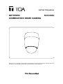
NETWORK
COMBINATION DOME CAMERA
N-CC2564
Thank you for purchasing TOA's Network Combination Dome Camera. Please carefully follow the
instructions in this manual to ensure long, trouble-free use of your equipment.
TABLE OF CONTENTS
1. SAFETY PRECAUTIONS ............................................................................... 3
2. LIST OF INCLUDED COMPONENTS AND PARTS ............................... 4
3. GENERAL DESCRIPTION ............................................................................. 5
4. FEATURES .......................................................................................................... 5
5. HANDLING PRECAUTIONS .......................................................................... 5
6. NOMENCLATURE .............................................................................................. 7
7. PRECAUTIONS WHEN INSTALLING THE UNIT .................................... 9
8. DIRECT CEILING MOUNTING
8.1. Mounting Example ............................................................................................. 9
8.2. Mounting Procedures ...................................................................................... 10
9. MOUNTING THE CAMERA TO A WEAK CEILING PANEL
9.1. Mounting Example ............................................................................................ 14
9.2. Mounting Procedures ....................................................................................... 15
10. FLUSH CEILING MOUNTING
10.1. Mounting Example .......................................................................................... 17
10.2. Mounting Procedures ..................................................................................... 18
11. CEILING SUSPENSION
11.1. Mounting Example .......................................................................................... 22
11.2. Mounting Procedures ..................................................................................... 23
12. WALL MOUNTING
12.1. Mounting Example .......................................................................................... 28
12.2. Mounting Procedures ..................................................................................... 28
13. CONNECTIONS
13.1. Connection example ....................................................................................... 31
14. INITIALIZATION ................................................................................................ 31
14.1. DIP Switch Settings ........................................................................................ 32
14.1.1. Communication Speed Setting Switch (DIP switch 2: No. 1 – 2) ......... 33
14.1.2. OSD Switch (DIP switch 2: No. 3) ....................................................... 33
14.1.3. Camera Unit Firmware Update Switch (DIP switch 3: No. 1 – 3) ........ 33
14.1.4. Memory Clear Switch (DIP switch 3: No. 7) ......................................... 33
15. TROUBLESHOOTING .................................................................................... 33
16. SPECIFICATIONS ............................................................................................ 34
System Requirements (for Software decoder) ........................................................ 37
Optional Products .................................................................................................... 37
2
1. SAFETY PRECAUTIONS
• Be sure to read the instructions in this section carefully before use.
• Make sure to observe the instructions in this manual as the conventions of safety symbols and messages
regarded as very important precautions are included.
• We also recommend you keep this instruction manual handy for future reference.
Safety Symbol and Message Conventions
Safety symbols and messages described below are used in this manual to prevent bodily injury and property
damage which could result from mishandling. Before operating your product, read this manual first and
understand the safety symbols and messages so you are thoroughly aware of the potential safety hazards.
WARNING
Do not expose the unit to rain or an environment where it may be
splashed by water or other liquids, as doing so may result in fire or
electric shock.
WARNING
Indicates a potentially hazardous situation which, if mishandled, could
result in death or serious personal injury.
When Installing the Unit
• This is a class A product. In a domestic environment this product may cause radio interference in which case
the user may be required to take adequate measures.
• Use the unit only with the voltage specified on the unit. Using a voltage higher than that which is specified
may result in fire or electric shock.
• Avoid installing the unit in unstable locations, such as on a rickety or slanted surface. Failure to do so may
result in the unit falling and possibly causing personal injury.
• Install the unit only in a location that can structurally support the weight of the unit and the mounting bracket.
Doing otherwise may result in the unit falling down and causing personal injury and/or property damage.
• Only use the unit's dedicated mounting hardware. The use of mounting hardware not designated could result
in the unit falling and possibly causing personal injury.
• Do not use other methods than specified to install the unit. Extreme force is applied to the unit and the unit
could fall off, possibly resulting in personal injuries.
• Attach the safety wire to the unit. If not attached, the unit could fall off, resulting in personal injury.
• Use nuts and bolts that are appropriate for the ceiling's or wall's structure and composition. Failure to do so
may cause the unit to fall, resulting in material damage and possible personal injury.
• Tighten each nut and bolt securely. Ensure that the bracket has no loose joints after installation to prevent
accidents that could result in personal injury.
• Avoid installing the unit in locations exposed to sea breeze or corrosive gas. Mounts may become corroded,
eventually causing the unit to fall off, which could result in personal injury.
• Do not mount the unit in locations exposed to constant vibration. The mounting screws and/or bolts may be
loosened by excessive vibration, potentially causing the unit to fall, which could result in personal injury.
When the Unit is in Use
• If any of the following irregularities occurs, immediately unplug the power plug from the AC outlet and inform
the shop from where the unit was purchased. Further using the unit may result in fire or electric shock.
· If you detect smoke or a strange smell coming from the unit.
· If water or any metallic object gets into the unit
· If the unit falls, or the unit case breaks
· If the power supply cord is damaged (exposure of the core, disconnection, etc.)
· If no camera images are displayed on the monitor TV when the temperature of the camera unit is 0°C or
more.
• To prevent a fire or electric shock, never open nor remove the unit case as there are high voltage
components inside the unit. Refer all servicing to your nearest TOA dealer.
• Do not insert, or drop metallic objects or flammable materials in the ventilation slots of the unit’s cover, as
this may result in fire or electric shock.
• Do not touch the unit during thunder and lightning, as this may result in electric shock.
3
CAUTION
Indicates a potentially hazardous situation which, if mishandled, could
result in moderate or minor personal injury, and/or property damage.
When Installing the Unit
• To avoid electric shocks, be sure to switch off the power before power supply wiring work. Failure to do so
may result in electrical shock.
• Leave the installation of the unit to your TOA dealer because the installation requires expert experience and
skills. If the unit falls, this could cause personal injures.
When the Unit is in Use
• Do not stand or sit on, nor hang down from the unit as this may cause it to fall down or drop, resulting in
personal injury and/or property damage.
• Switch off the power, and unplug the power supply plug form the AC outlet for safety purposes when
cleaning or leaving the unit unused for a long period of time. Doing otherwise may cause a fire, burn injury or
electric shock.
• Have the unit checked periodically by the shop from where it was purchased. Failure to do so may result in
corrosion or damage to the unit or its mounting brackets that could cause the unit to fall, possibly causing
personal injury.
• Contact your TOA dealer as to the cleaning. If dust is allowed to accumulate in the unit over a long period of
time, a fire or damage to the unit may result.
CU version complies with Part 15 of the FCC Rules.
Note
This equipment has been tested and found to comply with the limits for a Class A digital device,
pursuant to Part 15 of the FCC Rules. These limits are designed to provide reasonable protection
against harmful interference when the equipment is operated in a commercial environment. This
equipment generates, uses, and can radiate radio frequency energy and, if not installed and used in
accordance with the instruction manual, may cause harmful interference to radio communications.
Operation of this equipment in a residential area is likely to cause harmful interference in which case the
user will be required to correct the interference at his own expense.
Modifications
Any modifications made to this device that are not approved by TOA Corporation may void the authority
granted to the user by the FCC to operate this equipment.
2. LIST OF INCLUDED COMPONENTS AND PARTS
Check to be sure that the following components and parts are contained in the package:
Safety wire ......................................................................................................................... 1
Camera mounting screw (M4 x 8) ..................................................................................... 4
Category5 shielded coupler (female to female) ................................................................. 1
Extension connector (alarm input, AUX Contact output) .......................................... each 1
CD-ROM (Software decoder : N-SD2000, Manual (PDF)) ............................................... 1
Network Combination Dome Camera Installation Manual ................................................. 1
Software License Agreement ............................................................................................ 1
Network Camera System Installation Guide ...................................................................... 1
Note
The CD-ROM contains the Software Decoder, Software Decoder's Instruction Manual, Setting Manual,
N-DR2000 Status Monitoring Software, Instruction Manual and Installation Guide for N-DR2000 Status
Monitoring Software, Firmware, Adobe Acrobat Reader and DirectX.
4
3. GENERAL DESCRIPTION
The N-CC2564 Network Combination Dome Camera can be connected directly to a LAN (10BASET/100BASE TX). Since it can simultaneously transmit MPEG-4 and JPEG data, smooth moving images can
be monitored and high-definition still images can be monitored and recorded. The N-CC2564 can transmit
sub-band ADPCM or PCM quality voice.
TOA’s dome-type color cameras combine with a high-speed camera drive that permits one 360-degree
horizontal rotation per second and a 23 times optical zoom lens Up to 255 arbitrary positions can be preset
and such preset positions can be instantaneously repeated.
4. FEATURES
• Digital signal processing realizes high resolution and high picture quality. The unit also features the video
memory that increases the electronic sensitivity up to 32 times and enables electronic zooming.
• The supplied software decoder permits the images to be monitored via the network.
• It is also equipped with Timer, Motion Detection, Auto-flip, Wide Dynamic, Black & White mode, 12 times
Electronic Zooming and Privacy Masking functions
5. HANDLING PRECAUTIONS
• Noise may appear on the monitor or preset camera positions may deviate with prolonged camera use. In
such cases, use the camera’s refresh function to automatically refresh settings and reestablish the home
position once a day or week, thus allowing any position deviation to be corrected. When correcting manually,
display the menu screen using the software decoder and execute "Initialize" on the "Maintenance" items.
• It is recommended that the unit be installed in locations where the temperature is under +40°C, as the
longevity of the unit may reduce with prolonged unit use under high temperature and high humidity.
• Do not direct the camera lens to the sun or strong lighting or light reflection. Exposure to direct sunlight could
cause the CCD's color filter to deteriorate, leading to image discoloration.
• Do not install the unit in locations exposed to constant vibration. The unit is not intended for vehicle use. Do
not install the unit in a vehicle or ship.
• Do not give vibration or shock to the unit, as doing so may cause unit breakdown, or damage.
• Avoid installing the unit on sea or shore, or in locations exposed to dust or corrosive gas, or extraordinary
combustible conditions, or in swimming pools where disinfectants are used.
• To prevent the unit falls off, be sure to hang the supplied safety wire first when installing the unit.
• The dome camera is designed solely for suspended installations. The camera or dome must be suspended
vertically with its dome facing downward. Use special care not to suspend it at a tilted angle.
• Shielded (STP) network cables must be used with this unit to ensure compliance with EMC standards.
• The unit is not equipped with a power switch. Perform power construction work so that the camera power
can be turned on and off remotely.
• The dome camera features built-in heat generating circuitry. Take care not to touch the internal parts marked
"Caution High Temperature" when working inside the camera during dome cleaning or maintenance.
5
• Installing the camera cables in close proximity to fluorescent lamps or other electrical appliances can
downgrade the picture quality.
• If there is a strong electric or magnetic field near the camera, such as television transmission antennas,
motors or transformers, this may distort or roll the monitor picture. In such cases, run the entire wiring route
through metal conduit tubing.
• Before applying the power to the camera, be sure to complete all connections between the camera and
related equipment.
• Avoid directly touching the dome surface, since camera picture quality could deteriorate if the dome cover
becomes smudged and dirty.
• To clean, be sure to first unplug the power plug from the AC outlet, then wipe with a dry cloth. When the unit
gets very dirty, use a cloth dampened in a neutral detergent. Never use benzene, thinner or chemically
processed towel as the unit's plastic or other parts may be deformed or discolored.
• When cleaning the dome cover, wipe lightly with a soft cloth. In this event, the cover could be scratched and
damaged if the dome is covered in dust or sand. When the cover is extremely dirty, it is highly recommended
that the cover be removed and that its outside surface be washed lightly with water. Since alcohol-based
detergents can turn the dome cover whitish, avoid using them, as camera picture quality could be severely
affected.
• When dust has settled on the unit's lens, lightly clean using a commercial camera blower or cleaning paper.
• Install cables so as to prevent their damage and provide ample cable slack if they need to be stretched taut.
• The IP address, subnet mask and gateway IP address must be set.
• Transmission to multiple receivers using the unicast function could result in a reduction in the frame rate.
• When using the multicast function, the network must be compatible with the multicast system.
• When a connection is established between the transmitter and multiple receivers, if the data rate requested
by each receiver differs, the transmission will be limited to the minimum set data rate.
• In transmission streaming mode, data is constantly transmitted from transmitter to network even when no
communications are performed between the two.
• Personal computers running Microsoft Windows XP are required when performing initial settings for the
Network Combination Dome Camera.
• TOA's software decoder does not support Macintosh or Unix operating systems.
MPEG-4 visual patent portfolio license
With respect to a Licensee offering MPEG-4 Video Decoders and/or Encoders the following notice shall be
given:
THIS PRODUCT IS LICENSED UNDER THE MPEG-4 VISUAL PATENT PORTFOLIO LICENSE FOR THE
PERSONAL AND NON-COMMERCIAL USE OF A CONSUMER FOR (1) ENCODING VIDEO IN
COMPLIANCE WITH THE MPEG-4 VISUAL STANDARD (“MPEG-4 VIDEO”)AND/OR (2) DECODING
MPEG-4 VIDEO THAT WAS ENCODED BY A CONSUMER ENGAGED IN A PERSONAL AND NONCOMMERCIAL ACTIVITY AND/OR WAS OBTAINED FROM A VIDEO PROVIDER LICENSE BY MPEG LA
TO PROVIDE MPEG-4 VIDEO. NO LICENSE IS GRANTED OR SHALL BE IMPLIED FOR ANY OTHER
USE. ADDITIONAL INFORMATION INCLUDING THAT RELATING TO PROMOTIONAL, INTERNAL AND
COMMERCIAL USES AND LICENSING MAY BE OBTAINED FROM MPEG LA,LLC.
SEE HTTP://WWW.MPEGLA.COM.
6
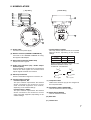
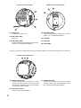
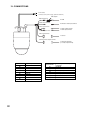
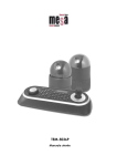
6. NOMENCLATURE
[ Front view ]
[ Top view ]
2
3
4
9
1
5
6
1
1
7
NETWORK COMBINATION DOME CAMERA
model N-CC2564 CU
24V
50 / 60Hz Max.16A
10
8
9
(1) Power Cable
Connects to the power supply.
(2) Network Terminal (10BASE-T/100BASE-TX)
Connects to the 10BASET/100BASE-TX using
the supplied LAN adapter.
(3) Video Output Terminal (VIDEO OUT)
Outputs the Video signals.
(4) Audio Input Terminal (red) / Audio Output
Terminal (white)
These terminals are comprised of a terminal that
receives line level signals and a terminal that
outputs signals received via a network.
• Contact Output 2 (AUX2)
This relay contact output controls its connected
external device, depending on the camera
settings.
OFF
ON
NO - COM
Open
Short
NC - COM
Short
Open
Rated maximum allowable voltage : 30 V DC
Maximum allowable current: 1 A
Contact life: 100,000 times
[ OFF ]
(5) Alarm Input Terminal
Used to receive alarm signals from sensors, etc.
(6) Contact Output Terminal
• Contact Output N1, N2
This open collector output allows the external
device connected to this terminal to control
other connected equipment via a network,
depending on the network settings.
• Contact Output 1 (AUX1)
This open collector output allows the external
device connected to this terminal to control
other connected equipment, depending on the
camera settings.
[ ON ]
NO
NO
COM
COM
NC
NC
(7) Composite Cable
Cables from terminals (2)-(6) are merged into
this composite cable.
(8) Initialization Switch (INITIALIZE)
Used to initialize the network settings.
(9) Reset Switch (RESET)
Used to restart the camera.
(10) Base Unit
(11) Camera Unit
7
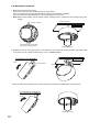
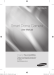
[ Bottom view of Camera Unit ]
[ Top view of Camera Unit ]
17
13
18
16
14
15
12
(12) Safety Wire
Connects to the base unit.
(15) DIP Switch (SW2)
Used to perform various settings of the camera.
(Refer to p. 32; DIP Switch Settings.)
(13) DIP Switch (SW1)
Not used.
(16) COM SW *
(14) DIP Switch (SW2)
Used to perform various settings of the camera.
(Refer to p. 32; DIP Switch Settings.)
(17) COM LED *
(18) COM PORT *
* Parts (16)-(18) are for maintenance purposes (firmware update) only. Avoid using these parts in normal use.
[ Bottom view of Base Unit ]
19
20
21
(19) READY LED (Green)
Flashes quickly when the camera is in initial
operation mode, and lights continuously while
the camera is operating. This LED also flashes
slowly during firmware rewrite.
(20) BUSY LED (Yellow)
Flashes during communications.
8
(21) ERROR LED (Red)
Lights when a failure occurs and camera
operation stops. This LED extinguishes when
the camera is automatically restarted.
7. PRECAUTIONS WHEN INSTALLING THE UNIT
WARNING
The Combination Dome Camera weight 2.0 kg. Select the heavy-duty
mounting surface that can structurally support the weight of the
camera. Doing otherwise may result in the unit falling and possibly
causing personal injury.
Notes
• Mount the camera to a heavy-duty ceiling surface (such as concrete ceiling).
• When mounting directly to the ceiling (such as a double ceiling) not strong enough to support the weight of
the mounted camera, use the optional C-BC511A Ceiling Mounting Bracket.
• When installing the camera in the ceiling to hide it as much as possible, use the optional C-BC511U or
C-BC511U-S Flush Ceiling Mounting Bracket.
• When hanging the camera from the ceiling, use the optional C-BC511P Ceiling Suspension Bracket.
• When mounting the camera to a wall, use the optional C-BC511W Wall Mounting Bracket.
8. DIRECT CEILING MOUNTING
Use the C-BC511C or C-BC511C-S Ceiling Mounting Cover.
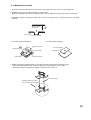
8.1. Mounting Example
[ Cable routing to the attic ]
[ Cable routing over the ceiling surface ]
1
1
1
1
Cut out this portion along the
perforated slot of the Base Unit
using nippers.
Perforated slot
9
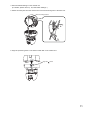
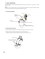
8.2. Mounting Procedures
1. Mount the base unit to the ceiling.
First fix two of the base unit mounting holes as shown below.
Since no mounting screws are supplied with the camera, prepare them separately.
Use screws with a nominal diameter of 4 mm and a length of over 25 mm.
Note: When routing cables over the ceiling surface, securely fix all 4 of the base unit mounting holes to the
ceiling.
Camera direction
Camera direction
Ceiling surface
Secure these two holes first.
(Base unit mounting holes)
Mounting screws
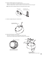
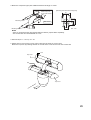
2. Release the lock on the hinged portion of the base unit, and connect the composite cable and power cable
to the base unit. (For details, please refer to p. 30; "CONNECTIONS.")
Ceiling surface
Open
Hinged portion
Open
3. Push up and lock the hinged portion of the base unit and secure the remaining two mounting holes.
Close
Mounting screws
10
4. Perform DIP SW settings on the camera unit.
(For details, please refer to p. 32; "DIP Switch Settings.")
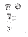
5. Attach the safety wire from the camera unit to the wire mounting hole of the base unit.
Wire mounting bracket
6. Align the positioning mark on the base unit with that on the camera unit.
Align the
marks
11
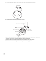
7. Align the positioning marks, then push the camera unit up into the base unit.
Push up
Screw section inside the base unit
is to be inserted into the oval hole
in the camera unit.
Note
Take care not to pinch the safety wire between the
camera unit and base unit to avoid damage to the
camera.
Note
When mounting the camera unit to the base unit,
mount it straight till it is attached to the base unit
correctly. Mounting it at an angle may cause
damage to the camera unit.
tallat
Angle
d ins
Mount straight
ion
8. Turn the camera unit clockwise pushing it up to the base unit until it locks into place.
12
9. Tighten 2 camera unit mounting screws.
Tighten
10. Align the positioning mark on the ceiling mounting cover with that on the base unit.
Align the
marks
Ceiling mounting cover
C-BC511C
C-BC511C-S
11. Turn the ceiling mounting cover clockwise pushing it up to the base unit until it locks into place.
13
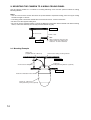
9. MOUNTING THE CAMERA TO A WEAK CEILING PANEL
Use the optional C-BC511C or C-BC511C-S Ceiling Mounting Cover and the optional C-BC511A Ceiling
Mounting Bracket.
Notes
• Use the cover and the anchor whenever the space between suspended ceiling panel and upper ceiling
exceeds a height of 100 mm.
• The ceiling panel to which the camera will be mounted must be 9 - 40 mm in thickness.
• Be sure to use the supplied safety wire.
• Be sure to use the specified screws to mount the Network Combination Dome Camera and direct mounting
anchor, and ensure that they are securely mounted without any play.
Upper ceiling
100 mm or more
40 mm or less
Ceiling panel
Note
When routing the wiring from the
ceiling surface, the ceiling panel
must be 9 - 40 mm in thickness.
9.1. Mounting Example
Safety wire
(supplied with the C-BC511A)
Anchor bolt for celing mounting bracket
Upper ceiling
Anchor bolt for safety wire
C-BC511A
Ceiling Mounting Bracket (optional)
Ceiling panel
Network Combination Dome camera
C-BC511C, C-BC511C-S
Ceiling Mounting Cover (optional)
14
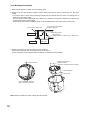
9.2. Mounting Procedures
1. Make a mounting hole of ø140 mm in the ceiling panel.
2. Install the anchor bolt for ceiling mounting bracket and anchor bolt for safety wire into the upper ceiling.
Notes
• The anchor bolt for ceiling mounting bracket must be aligned with the center of the mounting hole of ø140
mm in the ceiling panel, and must not project from the ceiling surface.
• If an existing anchor bolt is available nearby, it can be substituted for the anchor bolt for safety wire.
Upper ceiling
Anchor bolt for ceiling mounting bracket
Anchor bolt for safety wire
Ceiling surface
Ceiling panel
ø140 mm
3. Attach the supplied safety wire to the anchor bolt for safety wire.
4. Attach the ceiling mounting bracket to the end of the safety wire.
5. Attach the ceiling mounting bracket to the anchor bolt for ceiling mounting bracket.
Safety wire
3
Upper ceiling
Anchor bolt for ceiling
mounting bracket
C-BC511A
Ceiling Mounting Bracket
(optional)
5
Safety wire
(supplied with the C-BC511A)
* Ensure close contact here.
4
C-BC511A
Ceiling Mounting Bracket
(optional)
Ca
me
ra d
irec
tion
15
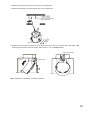
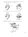
6. Attach the supplied safety wire to the base unit.
Use screws M3 x 8
tightened to the base unit.
7. Attach the safety wire connected to the base unit to the ceiling mounting bracket.
8. For subsequent procedures, follow the steps 1 – 11 on p. 10 – 13.
16
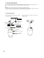
10. FLUSH CEILING MOUNTING
• Use the optional C-BC511U or C-BC511U-S Flush Ceiling Mounting Bracket.
• Flush mounting can be used to reduce the camera's exposed area. Use the optional C-BC511U or CBC511U-S Flush Ceiling Mounting Bracket when mounting cameras to gypsum board ceilings or other weak
ceiling panel materials in which mounting screws cannot be securely inserted.
Notes
• Use the bracket whenever the space between suspended ceiling panel and upper ceiling exceeds a height
of 250 mm.
• The ceiling panel to which the camera will be mounted must be no more than 40 mm in thickness.
• Be sure to use the supplied safety wire.
• Be sure to use the specified screws to mount the Network Combination Dome Camera and flush ceiling
mounting bracket, and ensure that they are securely mounted without any play.
Upper ceiling
250 mm or more
40 mm or less
Ceiling panel
10.1. Mounting Example
Safety wire
(supplied with the C-BC511U
and C-BC511U-S)
Anchor bolt for flush ceiling
mounting bracket
Upper ceiling
C-BC511U or C-BC511U-S
Flush Ceiling Mounting Bracket
(optional)
Anchor bolt for
safety wire
Ceiling panel
Network Combination Dome camera
17
10.2. Mounting Procedures
1. Make a mounting hole of ø230 mm in the ceiling panel.
2. Install the anchor bolt for flush ceiling mounting bracket and anchor bolt for safety wire into the upper
ceiling.
• The anchor bolt for flush ceiling mounting bracket must be aligned with the center of mounting hole of
ø230 mm in the ceiling panel.
• Use the pattern paper supplied with the C-BC511U or C-BC511U-S bracket to determine the anchor bolt
length and mounting surface height.
• If an existing anchor bolt is available nearby, it can be substituted for the anchor bolt for safety wire.
Anchor bolt for safety wire
Anchor bolt for flush ceiling
mounting bracket
Mounting surface
Upper ceiling
Ceiling panel
Paper pattern
(supplied with the C-BC511U or C-BC511U-S)
ø230 mm
3. Attach the base unit to the flush ceiling mounting bracket.
First fix two of the base unit mounting holes as shown below.
(Use the machine screws supplied with the Network Combination Dome Camera.)
Camera direction
Machine screws M4 x 8
(supplied with the
Network Combination Dome Camera)
Camera direction
Camera front
Secure these two holes first.
(Base unit mounting holes)
Note: Route the cables from flush ceiling mounting bracket.
18
4. Attach the supplied safety wire to the anchor bolt for safety wire.
5. Attach the flush ceiling mounting bracket to the end of safety wire.
Upper ceiling
4
Anchor bolt flush ceiling
mounting bracket
Notch
Ca
dir mer
ec a
tio
n
5
6. Release the lock on the hinged portion of the base unit and connect the composite cable and power cable
extending from the base unit. (For details, please refer to p. 30; "CONNECTIONS.")
Cable entry opening
Open
Hinged portion
Note: Squeeze the cables after connection completion.
19
7. Place the flush ceiling mounting bracket in the ceiling behind the ceiling panel by inserting it through the
mounting hole in the ceiling panel, then secure the bracket using the three supplied ceiling mounting
screws.
Turning the mounting screws clockwise clamps the ceiling holding plate to the ceiling panel. Ensure that the
notch in the bracket is pointing in the camera's intended direction.
7
Ca
me
Ceiling panel
ra
d
ire
cti
o
n
Flush ceiling mounting
bracket
Ceiling holding plate
Ceiling panel
mounting screws
Turn clockwise.
Notch
8. Fix the flush ceiling mounting bracket to the anchor bolt for flush ceiling mounting.
Cable entry opening
Tighten
9. Perform steps 3 – 5 on p. 10 – 11.
Note: Squeeze the cables after connection completion.
20
10. Attach the camera unit to the base unit.
Align the positioning mark on the camera unit with that on the flush ceiling mounting bracket.
Align the notch with
mark.
11. Perform steps 7 – 9 on p. 12 – 13.
12. Align the positioning mark on the supplied dome cover with the notch in flush ceiling mounting bracket.
13. Turn the dome cover counterclockwise pushing it up to the flush ceiling mounting bracket until it locks into
place.
12
Align the notch
with mark.
13
21
11. CEILING SUSPENSION
Use the optional C-BC511P Ceiling Suspension Bracket in combination with the optional C-BC511C or CBC511C-S Ceiling Mounting Cover when suspending the camera from a ceiling.
Notes
• Be sure to mount the ceiling suspension bracket using the supplied safety wire.
• Be sure to use the specified screws to mount the Network Combination Dome Camera and ceiling
suspension bracket, and ensure that they are securely mounted without any play.
11.1. Mounting Example
• When suspending the camera from a doubleconstructed ceiling
Anchor bolt for
safety wire
Saddle bracket
Footing
• When suspending the camera from the strong
ceiling materials
Upper ceiling
Safety wire
(supplied with the
C-BC511P)
Suspension plate
(separately required part)
Ceiling plate
Top cover
C-BC511P Ceiling Suspension
Bracket (optional)
Footing/Saddle
Network
Combination Dome Camera
C-BC511C or C-BC511C-S
Ceiling Mounting Cover
(optional)
22
11.2. Mounting Procedures
1. Determine the suspending position, then make a mounting hole of ø50 – 60 mm in the ceiling plate.
2. Install the anchor bolt for safety wire into the upper ceiling.
Note: If an existing anchor bolt is available nearby, it can be substituted for the anchor bolt for safety wire.
3. Separately prepare a suspension plate, and cut out the necessary hole in a way best suited to the plate
material.
Anchor bolt for
safety wire
2
1
Ceiling panel
ø50 mm – 60 mm
• For strong ceiling materials
• For double-constructed ceilings
Suspension plate
Camera direction
Paper pattern
Ceiling plate
Suspension plate
Ceiling panel
C-shaped channel
4. Detach footings and saddle bracket on the camera mounting side from the suspension pipe.
• Removed saddle brackets and screws are attached to the suspension pipe in step 10.
• Removed footings and screws are attached to the base unit in step 12.
Suspension pipe
Saddle bracket and footing
on the camera mounting side
23
5. Attach the suspension pipe (saddle bracket and footing) to the suspension plate.
Note: Ensure that the installed suspension pipe faces in the intended camera orientation.
[Mounting hole dimensional diagram]
81
Footing
Saddle bracket
46
Suspension pipe
40
70
ra n
me
Ca entatio
ori
Unit: mm
6. Install the suspension plate behind the ceiling panel.
• When installing in double-constructed ceilings:
Place the suspension plate across two C-channel bars with its hole aligned with the corresponding hole in
the ceiling panel.
• When installing in strong ceiling materials:
Install the suspension plate with its hole aligned with the corresponding hole in the ceiling panel.
7. Attach the supplied safety wire to the anchor bolt for safety wire.
8. Attach the end of the safety wire to the saddle bracket of the suspension pipe.
9. Run the composite cable and power cable extending from the ceiling through the pipe.
9
Anchor bolt for safety wire
Composite cable
Upper ceiling
Power cable
6
7
Saddle bracket
Suspension plate
(to be prepared separately)
Ceiling panel
8
Safety wire
(supplied with the C-BC511P)
C-channel bar
(to be prepared separately)
Suspension pipe
24
10. Attach two saddle brackets to the suspension pipe.
• Align the screw installed in the saddle bracket with the hole in the pipe.
• Attach the saddle bracket so that the orientation of its oval holes is as shown in the figure.
Note: Ensure that the saddle brackets are securely fixed without any play.
Saddle bracket
Suspension pipe
mounted to the ceiling.
Screw
Oval hole
11. Attach the supplied safety wire to the base unit.
Use screws M3 x 8
tightened to the base unit.
12. Attach removed footings to the base unit.
• First fix two of the base unit mounting holes as shown below.
• Use the screws supplied with the Network Combination Dome Camera.
Camera direction
Footing
a
er
m tion
a
C irec
d
Secure these two holes first.
(Base unit mounting holes)
M4 x 8 machine screw
(supplied with the
Network Combination Dome Camera)
25
13. Attach the safety wire attached to the base unit to the saddle bracket of the suspension pipe.
14. Attach the base unit (with footing) to the suspension pipe.
Oval hole in the saddle bracket
M4 x 20 Camera mounting
screw
M5 x 20 Safety screw
Screw head
sliding direction
Base unit
ra
me n
Ca ectio
dir
• Run the camera mounting screw head (2 screws) through the oval hole in the saddle bracket, and slide it in
the direction indicated by the arrow, then tighten the camera mounting screws.
• Tighten the safety screw and run its screw tip through the round hole in the saddle bracket.
Note: Ensure that camera mounting screws and safety screw are securely tightened.
26
15. Release the lock on the hinged portion of the base unit and connect the power and composite cables to
the base unit. (For details, please refer to p. 30; "CONNECTIONS.")
Open
Hinged portion
Open
16. Lock the hinged portion of the base unit and secure the remaining two mounting holes.
Hinged portion
Close
M4 x 8 screws supplied with
the network combination camera
17. Perform steps 4 – 11 on p. 11 – 13.
18. Mount the top cover by inserting the tabs of one half of the cover into the slots of the other half.
Top cover
Tab
Tab
Top cover
Ca
me
ra
e
dir
cti
on
27
12. WALL MOUNTING
Use the optional C-BC511W Wall Mounting Bracket and optional C-BC511C or C-BC511C-S, Ceiling
Mounting Cover.
Note
Be sure to use the specified screws to mount the Network Combination Dome Camera and wall mounting
bracket, and ensure that they are securely mounted without any play.
12.1. Mounting Example
Top cover
C-BC511W
Wall Mounting Bracket
(optional)
Wall surface
Top cover
Network
Combination Dome Camera
Saddle bracket and footing
C-BC511C or C-BC511C-S
Ceiling Mounting Cover (optional)
12.2. Mounting Procedures
1. Determine the mounting position, then make a mounting hole of ø50 – 60 mm on a wall.
2. Detach footings on the camera mounting side from the suspension pipe.
Removed footings and screws are attached to the base unit later. (refer to p. 24)
Suspension pipe
Footings and saddle bracket
on the camera mounting side
28
3. Mount the suspension pipe (with saddle bracket and footings) on a wall.
[Mounting hole dimensional diagram]
Cable entry hole
on the wall surface
81
46
Wall surface
40
Mounting screw
70
Mounting screw
Unit: mm
Notes
• Since no mounting screws are supplied with the camera, prepare them separately.
• Use screws with a nominal diameter of 4 mm.
4. Perform steps 11 – 16 on p. 25 – 27.
5. Attach the top cover. Insert one top cover's clicks into the other top cover's slots.
Mount the top cover by inserting the tabs of one half of the cover into the slots of the other half.
Tab
Top cover
Tab
Top cover
on
cti
ra
me
e
dir
Ca
29
13. CONNECTIONS
Power cable;
Connects to the power supply. (24V AC 50/60 Hz)
LAN adapter
Network terminal
To HUB
Video output terminal
To Monitor's Video input terminal
Audio input terminal
To audio output terminal
To audio input terminal
Audio output terminal
Alarm input terminal
To sensor
1
Auxiliary Contact output terminal
To external equipment
(to contact input terminal)
1
Terminal No.
(1)
(2)
(3)
(4)
(5)
(6)
(7)
(8)
(9)
30
Alarm input terminal
Alarm1
Alarm2
Alarm3
Alarm4
Alarm5
Alarm6
Alarm7
Alarm8
GND
Terminal No.
(1)
(2)
(3)
(4)
(5)
(6)
(7)
Auxiliary Contact output
terminal
AUX N1
AUX N2
AUX2 (NO)
AUX2 (COM)
AUX2 (NC)
AUX1
COM
13.1. Connection example
Connections to the network system differ depending on the devices to be used.
For details, refer to the descriptions about system examples in the setup manual.
Switching HUB
8
7
6
5
4
3
2
1
DC-IN
To AC
N-SD2000
Software Decoder
N-CC2564 Network
Combination Dome Camera
: 10BASE-T/100BASE-TX
: 100BASE-TX/1000BASE-T
To 24 V AC
Note: Shielded (STP) network cables must be used with this unit to ensure compliance with EMC standards.
14. INITIALIZATION
Return the set contents to default conditions.
1. Either press the RESET switch or switch on the power again while holding down the INITIALIZE switch.
2. Continue to press the INITIALIZE switch until the Ready indicator on the switching hub lights.
Note
To return the camera settings to default conditions, execute it in the camera menu screen. For details, refer to
the setting manual.
31
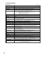
14.1. DIP Switch Settings
DIP SW1
DIP SW2
DIP SW3
DIP SW1
DIP SW2
DIP SW3
Camera Unit Firmware
update switch 1
No.1
Unused (ON)
Communication speed setting
switch 1
No.2
Unused (OFF)
Communication speed setting
switch 2
Camera Unit Firmware
update switch 2
No.3
Unused (OFF)
OSD switch
Camera Unit Firmware
update switch 3
No.4
Unused (OFF)
Unused (OFF)
Unused (OFF)
No.5
Unused (OFF)
Unused (OFF)
Unused (OFF)
No.6
Unused (OFF)
Unused (ON)
Unused (OFF)
No.7
Unused (OFF)
Unused (OFF)
Memory clear switch
No.8
Unused (OFF)
Unused (OFF)
Unused (OFF)
Note: If the DIP switches are not set correctly, the camera does not operate correctly.
32
14.1.1. Communication Speed Setting Switch (DIP switch 2: No. 1 – 2)
Avoid changing the default settings. ("38,400 bps" is the default.)
No.1
OFF
ON
OFF
ON
No.2
OFF
OFF
ON
ON
bps
38,400
19,200
9,600
4,800
14.1.2. OSD Switch (DIP switch 2: No. 3)
When this switch is set to the OFF position, the initial screen does not disappear until communications with
other equipment are established following initial operation after the power has been switched ON.
(Factory setting: OFF)
14.1.3. Camera Unit Firmware Update Switch (DIP switch 3 No. 1 – 3)
For details, refer to the Camera Controller Software Operation Manual.
The Camera Controller Software Operation Manual and Installation Guide are made available on the TOA
product data download site (http://www.toa-products.com/international/).
14.1.4. Memory Clear Switch (DIP switch 3: No. 7)
Switching on the power with this switch set to the ON position returns all camera settings to the initial setting.
The indication "Memory Clear" is displayed on the screen while clearing memory. After the indication has
disappeared, turn off the power and set the switch to the OFF position.
Note: Clock information and backup data are not erased.
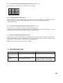
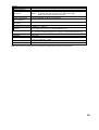
15. TROUBLESHOOTING
Remedy
Symptom
Possible Cause
Supply power to the camera.
Camera does not start. Power is not supplied.
(Ready LED does not
light.)
LINK/ACT LED does Cable is not correctly connected to Confirm that the cable type (category, null
modem or straight) is appropriate for the
not light.
the unit's network terminal.
connected port, then connect correctly.
33
16. SPECIFICATIONS
[N-CC2564 CU]
Power Source
Power Consumption
Video Output
Audio Input
Audio Output
Alarm Input
Auxiliary Contact Output
Camera
Image Device
Resolution
S/N Ratio
Synchronization
* 0 dB = 1V
24 V AC, 50/60 Hz
20 W (normal operation), 25 W max. (1.6 A max.)
VBS 1.0 V(p-p), 75 Ω, BNC-R jack, NTSC
1 channel, -10 dB*, 10 kΩ, unbalanced, RCA pin jack
1 channel, -10 dB*, low impedance, unbalanced, RCA pin jack
8 channels, no-voltage make contact input, open voltage: 9 V DC,
short-circuit current: Under 10 mA (settable alarm action)
3 channels: Open collector output, withstand voltage: 30 V DC,
permissible current: Under 50 mA,
1 channel: Relay contact output, permissible voltage: 30 V DC,
permissible current: Under 1 A
1/4 type CCD
Horizontal: 480 lines (at center)
50 dB
Internal synchronization/Power synchronization (phase adjustable when in
power synchronization mode)
High-sensitivity function OFF: 3 lx (50 IRE), 1 lx (20 IRE)
Minimum Required
High-sensitivity function ON: 0.03 lx (50 IRE), 0.01 lx (20 IRE)
Illumination
Backlight Compensation WIDE DYNAMIC/ Pattern1/ Pattern2/ Pattern3/ OFF
46 dB (backlight compensation: WIDE DYNAMIC operation)
Dynamic Range
High-Sensitivity Function B/W mode and slow shutter mode (32 times max.)
ATW/ AWB
White Balance
Automatic correction
Flicker Reduction
8 characters (alphanumeric and symbols)
ID
Camera, Position, Trace, Auto-pan, Tour, Home, Alarm, Sector, AUX
No. of Preset Positions 255 positions + Home
Auto-pan, Preset sequence, Auto-trace (2 preset patterns (60 s)),
Automatic Operation
Tour (16 preset patterns)
Refresh: Starts at the preset time every day or every week by timer settings
Timer
Program: Settable 16 actions
Auto flip, Freeze preset, Manual limit, Privacy masking (up to 8),
Other Function
Motion detection (each 8 presets at each 4 positions)
Lens
12 x zooming
Electronic Zooming
One push/ stop AF/ continuous
Auto-Focus
23 x
Zooming
f = 3.6 – 82.8 mm (23 x)
Effective Focal Length
Effective Angle of View Horizontal: 54° (W) – 2.5° (T), Vertical: 41.6° (W) – 1.9° (T)
F 1.6 (W) – F 3.7 (T)
Maximum Aperture
WIDE end to TELE end
Zoom Speed
Approx. 1.5 s (preset operation), Approx. 2.9 s (manual operation)
Pan/Tilt Head
Panning: Endless 360° rotation, Tilting: +5° to –185°
Rotating Range
Panning/Tilting: 360°/s max. (preset operation),
Rotating Speed
360°/s max. (manual operation)
34
Network
Network I/F
Network Protocol
Video Compression/
Resolution
Frame Rate
Audio Compression/
Decompression
Audio Sampling
Frequency
Image Transfer Rate
Simultaneous Connected
Number
Operating Temperature
Operating Humidity
Application
Finish
Dimensions
Weight
10BASE-T/100BASE-TX, Auto-Nego/Manual: RJ45 connector
TCP, UDP, SIP, RTP, IGMP, HTTP, ARP, DHCP, DNS, SNTP, FTP, SMTP
MPEG-4: D1 (720 x 480), Half D1 (720 x 240), QVGA (320 x 240)
JPEG:
D1 (720 x 480), Half D1 (720 x 240), VGA (640 x 480),
QVGA (320 x 240), QQVGA (160 x 120)
MPEG-4: (D1, max. 30 fps) + JPEG (D1, max. 5 fps)
Sub-band ADPCM, PCM (non-compression)
8 kHz, 32 kHz
MPEG-4: max. 4 Mbps
5 (MPEG-4: 4, JPEG: 1),
When streaming mode is set: No limit (MPEG-4 only)
–10°C to +50°C (continuously active for operation at temperature below 0°C)
14°F to 122°F (continuously active for operation at temperature below 32°F)
Under 90% RH (no condensation)
Indoor use
Base:
PC/ABS resin, cool gray
Camera: PC/ABS resin, black
ø168 x 234 (H) mm (ø 6.61" x 9.21")
2 kg (4.41 lb)
Note: The design and specifications are subject to change without notice for improvement.
35
[N-CC2564 PL]
Power Source
Power Consumption
Video Output
Audio Input
Audio Output
Alarm Input
Auxiliary Contact Output
Camera
Image Device
Resolution
S/N Ratio
Synchronization
* 0 dB = 1V
24 V AC, 50/60 Hz
20 W (normal operation), 25 W max. (1.6 A max.)
VBS 1.0 V(p-p), 75 Ω, BNC-R jack, PAL
1 channel, -10 dB*, 10 kΩ, unbalanced, RCA pin jack
1 channel, -10 dB*, low impedance, unbalanced, RCA pin jack
8 channels, no-voltage make contact input, open voltage: 9 V DC,
short-circuit current: Under 10 mA (settable alarm action)
3 channels: Open collector output, withstand voltage: 30 V DC,
permissible current: Under 50 mA,
1 channel: Relay contact output, permissible voltage: 30 V DC,
permissible current: Under 1 A
1/4 type CCD
Horizontal: 480 lines (at center)
50 dB
Internal synchronization/Power synchronization (phase adjustable when in
power synchronization mode)
High-sensitivity function OFF: 3 lx (350 mV), 1 lx (140 mV)
Minimum Required
High-sensitivity function ON: 0.03 lx (350 mV), 0.01 lx (140 mV)
Illumination
Backlight Compensation WIDE DYNAMIC/ Pattern1/ Pattern2/ Pattern3/ OFF
46 dB (backlight compensation: WIDE DYNAMIC operation)
Dynamic Range
High-Sensitivity Function B/W mode and slow shutter mode (32 times max.)
ATW/ AWB
White Balance
Automatic correction
Flicker Reduction
8 characters (alphanumeric and symbols)
ID
Camera, Position, Trace, Auto-pan, Tour, Home, Alarm, Sector, AUX
No. of Preset Positions 255 positions + Home
Auto-pan, Preset sequence, Auto-trace (2 preset patterns (60 s)),
Automatic Operation
Tour (16 preset patterns)
Refresh: Starts at the preset time every day or every week by timer settings
Timer
Program: Settable 16 actions
Auto flip, Freeze preset, Manual limit, Privacy masking (up to 8),
Other Function
Motion detection (each 8 presets at each 4 positions)
Lens
12 x zooming
Electronic Zooming
One push/ stop AF/ continuous
Auto-Focus
23 x
Zooming
f = 3.6 – 82.8 mm (23 x)
Effective Focal Length
Effective Angle of View Horizontal: 54° (W) – 2.5° (T), Vertical: 41.6° (W) – 1.9° (T)
F 1.6 (W) – F 3.7 (T)
Maximum Aperture
WIDE end to TELE end
Zoom Speed
Approx. 1.5 s (preset operation), Approx. 2.9 s (manual operation)
Pan/Tilt Head
Panning: Endless 360° rotation, Tilting: +5° to –185°
Rotating Range
Panning/Tilting: 360°/s max. (preset operation),
Rotating Speed
360°/s max. (manual operation)
36
Network
Network I/F
Network Protocol
Video Compression/
Resolution
Frame Rate
Audio Compression/
Decompression
Audio Sampling
Frequency
Image Transfer Rate
Simultaneous Connected
Number
Operating Temperature
Operating Humidity
Application
Finish
Dimensions
Weight
10BASE-T/100BASE-TX, Auto-Nego/Manual: RJ45 connector
TCP, UDP, SIP, RTP, IGMP, HTTP, ARP, DHCP, DNS, SNTP, FTP, SMTP
MPEG-4: D1 (720 x 576), Half D1 (720 x 288), CIF (352 x 288)
JPEG:
D1 (720 x 576), Half D1 (720 x 288), CIF (352 x 288),
VGA (640 x 480), QVGA (320 x 240), QQVGA (160 x 120)
MPEG-4: (D1, max. 25 fps) + JPEG (D1, max. 5 fps)
Sub-band ADPCM, PCM (non-compression)
8 kHz, 32 kHz
MPEG-4: max. 4 Mbps
5 (MPEG-4: 4, JPEG: 1),
When streaming mode is set: No limit (MPEG-4 only)
–10°C to +50°C (continuously active for operation at temperature below 0°C)
14°F to 122°F (continuously active for operation at temperature below 32°F)
Under 90% RH (no condensation)
Indoor use
Base:
PC/ABS resin, cool gray
Camera: PC/ABS resin, black
ø168 x 234 (H) mm (ø 6.61" x 9.21")
2 kg (4.41 lb)
Note: The design and specifications are subject to change without notice for improvement.
• System Requirements (for Software decoder)
Personal Computer
Main Specifications
OS
Required Web Browser
PC/AT compatible
CPU:
Pentium4, over 3 GHz
Memory:
Over 512 MB
Display adapter: XGA (1024 x 768 pixels), Intel Chipset (Recommended)
Usable on DirectX 9.0a or later
Sound controller: Usable over DirectX 9.0a or later
Network adapter: Over 100BASE-TX
Windows XP Professional
Internet Explorer 6.0 or later
Notes
• Pentium and Intel are trademark of Intel Corporation.
• Windows is a trademark of Microsoft Corporation.
• Optional products
Ceiling Mounting Cover:
Flush Ceiling Mounting Bracket:
Ceiling Suspension Bracket:
Wall Mounting Bracket:
Ceiling Mounting Bracket:
C-BC511C/ C-BC511C-S
C-BC511U/ C-BC511U-S
C-BC511P
C-BC511W
C-BC511A
37
38
39
URL: http://www.toa.jp/
133-22-018-0A