1
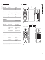
T: +44 (0) 1236 420199
F: +44 (0) 1236 428230
E: [email protected]
Tannoy North America
T: (519) 745 1158
F: (519) 745 2364
E: [email protected]
Tannoy Deutschland
T: (04102) 888 393
F: (04102) 888 959
E: [email protected]
Tannoy adopts a policy of continuous improvement and product specification is subject to change.
6D & 8D ACTIVE STUDIO MONITORS
6481 0412
0414
Tannoy United Kingdom
O W N E R S
M A N U A L
CONTENTS
1.0: IMPORTANT SAFETY INSTRUCTIONS
1.0: IMPORTANT SAFETY INSTRUCTIONS
1.1
Introduction
2.0: THE BASICS
2.1
2.2
Unpacking and visual checks
Preliminary recommendation
3.0: PRECISION D SERIES FEATURES
3.1
3.2
3.3
3.4
Analog Input
Digital SPDIF Input
Connecting your speakers
User Controls
1.
2.
3.
4.
5.
6.
7.
8.
9.
4.0: EQUALISATION POSSIBILITIES
10.
5.0: GUIDE TO SETTING THE EQUALISATION
6.0: PLACEMENT OF THE SPEAKERS
7.0: PERFORMANCE DATA
6.1
6.2
6.3
6.4
6.5
Orientation (R6D & R8D)
Positioning (R6D & R8D)
Positioning (R66D)
Speaker Mounting
Bass Ports
Precision 6
Precision 8
8.0: TECHNICAL SPECIFICATIONS
11.0: WARRANTY
12.0: DECLARATION OF CONFORMITY
14.
15.
16.
17.
ELECTRICAL REQUIREMENTS
Check that the voltage rating displayed on the rear panel is correct for your area before connecting. If it is incorrect, please
refer to your local dealer or authorised service agent, as no user adjustment is provided.
9.0: DIMENSIONS
10.0: SERVICING
11.
12.
13.
Read these instructions.
The lightning flash with an arrowhead symbol within an
The exclamation point within an equilateral triangle is
equilateral triangle, is intended to alert the user to the
intended to alert the user to the presence of important
Keep these instructions.
presence of uninsulated “dangerous voltage” within the
operating and maintenance (servicing) instructions in the
product’s enclosure that may be of sufficient magnitude
literature accompanying the product.
Heed all warnings.
to constitute a risk of electric shock to persons.
Follow all instructions.
Do not use this apparatus near water.
Clean only with dry cloth.
Do not block any ventilation openings. Install in accordance with manufacturer’s instructions.
Do not install near any heat sources such as radiators, heat registers, stoves, or other apparatus (including amplifiers) that
produce heat and ensure adequate air circulation around the rear of the product.
Do not defeat the safety purpose of the polarised or grounding-type plug. A polarised plug has two blades with one wider
than the other. A grounding type plug has two blades and a third grounding prong. The wide blade or the third prong are
provided for your safety. If the provided plug does not fit into your outlet, consult an electrician for replacement of the
obsolete outlet.
Protect the power cord from being walked on or pinched particularly at plugs, wall sockets, and the point where they exit
from the apparatus.
Only use attachments/accessories specified by the manufacturer.
Unplug this apparatus during lightning storms or when unused for long periods of time.
Refer all servicing to qualified service personnel. Servicing is required when the apparatus has been damaged in any way,
such as power-supply cord or plug is damaged, liquid has been spilled or objects have fallen into the apparatus, the
apparatus has been exposed to rain or moisture, does not operate normally, or has been dropped.
WARNING: To reduce the risk of fire or electrical shock, this apparatus should not be exposed to rain or moisture and objects
filled with liquids, such as vases, should not be placed on this apparatus.
To completely disconnect this equipment from the mains, disconnect the power supply cord plug from the wall socket.
The mains plug on the power supply cord shall remain readily accessible.
SAFETY WARNING: This product design uses amplifier output stages with substantial standing currents for optimal sound
quality. Fit and use the protective heat shield when adjusting the feature controls above the heatsink, to prevent contact
with uncomfortably hot surfaces when monitoring at continuously high sound pressure levels. Use the small tool provided
to adjust the switches in accordance with the instructions in the user manual.
6.1
6.2
6.3
6.4
Cabinet Finish
Driver Removal
Amplifier Removal
Spare parts
Warning!
• To reduce the risk of fire or electric shock, do not expose this apparatus to rain or moisture.
• Be advised that different operating voltages require the use of different types of line cord and attachment plugs.
• Check the voltage in your area and use the correct type. See table below:
Voltage
110-125V
220-230V
240V
Line plug according to standard
UL817 and CSA C22.2 no 42.
CEE 7 page VII, SR section 107-2-D1/IEC 83 page C4.
BS 1363 of 1984. Specification for 13A fused plugs and switched and un-switched socket outlets.
Service
There are no user-serviceable parts inside. Qualified personnel must perform all service. Servicing is required when: • The unit has been damaged in any way, such as when the power-supply cord or plug is damaged.
• The unit has been exposed to rain or moisture, or liquid has been spilled into the unit.
• Objects have fallen into the unit.
• The unit does not work properly.
• The unit has been dropped.
EUROPEAN MODELS
A mains cable is supplied with an IEC moulded socket at one end and a moulded mains plug at the other end. Where the
moulded plug is fitted with a mains fuse, always replace with the same 5A rated fuse. If the fitted plug is unsuitable for your
type of outlet sockets, it should be cut off and disposed of safely, in case it is inserted into a live socket elsewhere. The wires in
the mains cable are coloured in accordance with the following code:
GREEN AND YELLOW EARTH
2
BLUE NEUTRAL
BROWN LIVE
3
AS THE COLOURS OF THE WIRES IN THE MAINS CABLE MAY NOT CORRESPOND WITH THE COLOURED MARKINGS
IDENTIFYING THE TERMINALS IN YOUR PLUG, PROCEED AS FOLLOWS:
The wire which is coloured GREEN AND YELLOW must be connected to the terminal in the plug which is marked either by the
letter E, the earth safety symbol, or coloured GREEN or GREEN and YELLOW.
The wire which is coloured BLUE must be connected to the terminal in the plug which is marked by the letter N or coloured BLACK
The wire which is coloured BROWN must be connected to the terminal in the plug which is marked by the letter L or coloured RED.
Ensure that the terminals are tightened securely, and no loose strands of wire are present. Ensure cord grip is clamped over
outer sheath of cable, rather than over the wires.
FUSE PROTECTION
An additional mains fuse is provided in the IEC power inlet on the back of the loudspeaker, which can only be removed with
the power cord unplugged. This must be replaced by a fuse of the same type and ratings (see Specifications or refer to rear
panel).
INSTALLATION
Do not install this equipment in an enclosed space. Do not limit free ventilation and movement of air around the back panel.
Do not install this equipment in a cupboard with a closed door. Allow for a distance of 150mm (6 inches) of free air space
around all sides, top, bottom and the back panel of this product. The user must be able to see the blue coloured front panel
of this product when in use.
EMC
This equipment has been tested and found to comply with the limits for a Class B digital device, pursuant to part 15 of the FCC
Rules. These limits are designed to provide reasonable protection against harmful interference in a residential installation. This
equipment generates uses and can radiate radio frequency energy and, if not installed and used in accordance with the
instructions, may cause harmful interference to radio communications. However, there is no guarantee that interference will not
occur in a particular installation. If this equipment does cause harmful interference to radio or television reception, which can
be determined by turning the equipment off and on, the user is encouraged to try to correct the interference by one or more of
the following measures:
Reorient or relocate the receiving antenna.
Increase the separation between the equipment and receiver.
Connect the equipment into an outlet on a circuit different from that to which the receiver is connected.
Reorient or coil cables.
If necessary, consult the dealer or an experienced radio/television technician for additional suggestions.
Any cables the user adds to the device must be shielded to be in compliance with the FCC standards. Any unauthorised modification
to this device could result in the revocation of the end user’s authority to operate this device.
This device complies with Part 15 of FCC rules. Operation is subject to the following two conditions: (1) This device may not
cause harmful interference, and (2) This device must accept any interference received, including interference that may cause
undesired operation.
Canada
Industry Canada Class B emission compliance statement. This Class B digital apparatus complies with Canadian ICES-003.
Avis de conformite a la reglementation d'Industrie Canada. Cet appareil numerique de classe B est conforme a la norme NMB003 du Canada.
Characteristic of the Dual design is a very wide 'sweet spot' with an exceptionally even response throughout the listening area
and extraordinary transient response. This phase accurate Tannoy designed drive unit has, for all these reasons, been the choice
of professional studio engineers for decades.
Tannoy has been at the forefront of developing loudspeakers with WideBand™ performance. Extending the high frequency rolloff out to 51kHz corrects the time or phase response at the upper end of audibility, resulting in enhanced accuracy and ‘air’,
improved clarity within the essential mid band area, and even enhancing definition of low frequencies. Tannoy WideBand™
Technology is an essential component of the Precision monitor design delivering increased tonal accuracy of the individual
instruments in the recording process - a mix-critical factor allowing the best EQ and placement decisions to be made.
Tannoy engineers have researched ways of dealing effectively with the acoustic effects of mid, near and close field listening
distances, in order to compensate for the relative size and distance of the acoustic source and resultant spherical / plane wave
dilemmas. Additionally, the effect of boundaries near a monitor speaker, such as walls, support tables and mixing console
surfaces can change the air load on the low frequency cone piston and consequently the radiating efficiency in the 100Hz to
800Hz region.
A set of DIP switches on the rear control panel of the new Precision D active monitors allow the selection of an optimum speaker
response for real life and often difficult monitoring situations so that the frequency response at the listener’s ears is always as
linear and flat as possible. Optimisation can be preset for far field (>2m), mid field (1to 2m), near field (0.5 to 1m) and close
field (<0.5m) situations in combination with free space (4pi), half space (2pi), quarter space (pi) and extreme eighth space (pi/2)
corner situations. Precision D Active monitors can therefore be optimised for varying listening distances in difficult acoustic spaces;
varying meter bridge positions, against and adjacent to walls or reflecting surfaces, in corners, in corners on shelves or brackets,
table top / space restricted PC/Mac based sound editing environments and stand mounted or soffit mounted configurations.
(see graph overlleaf).
2.0: THE BASICS
2.1: UNPACKING AND VISUAL CHECKS
The Precision 6 and precision 8 are packed singly. To remove the speaker from the carton without damage open the end flaps
fully and bend them right back. Turn the package upside-down on the floor and lift the carton vertically up to leave the speakers
resting on their packing tray. Nothing on or in your speakers should rattle about. Inspect each speaker for signs of transit damage.
In the unlikely event of this having occurred inform the carrier and the supplier. Keep all the packaging if damage has occurred,
as this will show evidence of excessive handling forces. It is also a good idea to keep the packaging if possible for future
transportation.
2.2: PRELIMINARY RECOMMENDATION
Initially we would like to give a word of warning on high sound levels, which these speakers are capable of generating over
sustained periods of time. Levels over 95 dB for 8 hours per day can eventually cause permanent hearing loss. Because Tannoy
monitors have very low levels of time, amplitude and frequency distortion it is not always obvious that the sound level is high
while working with them.
For continuous exposure we recommend the occasional use of a sound level meter capable of integrating the sound level over
a period of exposure according to noise control standards. This should be used just to check that noise levels are always within
safety limits.
1.1: INTRODUCTION
3.0: PRECISION D SERIES FEATURES
Taking full advantage of significant advances in digital speaker measuring techniques such as Klippell™ symmetry and nonlinear
distortion analysis, laser scanning interferometry, acoustic CAD simulation and our own cutting edge acoustic technologies,
Tannoy engineers have developed two new active monitors. The new Precision D range incorporates the latest Tannoy Dual
Concentric™ driver and WideBand™ Technology to deliver near field monitoring speaker designs that set new standards of
acoustic performance and accuracy.
A set of DIP switches on the rear panel of each speaker can be set to choose the optimum speaker response for real life and
often difficult situations, so that the frequency response from the speaker is always substantially flat. We are not equalising the
room modes due to standing waves or resonant structures, we are equalising the speaker to take account of the varying air load
presented by the room and surrounding large structures such as the mixing desk.
Precision D active monitors provide superior bandwidth, significantly low levels of distortion, very smooth response, extremely
accurate phase control, high sensitivity levels and input source flexibility. Add in a comprehensive calibrated EQ facility for mid
/ near / close field working in full / half /quarter and eighth space environments, midband and high frequency trim shelving
controls, a choice of power and cabinet sizes, analogue and digital input trim facilities, and user requirements can be satisfied
for all listening environments and applications.
4
Tannoy’s core technology, the Dual Concentric™ is unlike ordinary drive units in that it is effectively two drivers, properly merged
into one. The high-frequency unit is positioned on the back of the low frequency driver so that they are on the same axis. As a
result sound energy is propagated from the same point and delivered through the centre of the low frequency cone providing
a true point source. This integrated approach provides a constant time delay over the frequency spectrum offering better transient
performance and sound quality with better harmonic alignment than a displaced source monitor design. The crucial benefit at
the mix position is the delivery of a more natural and cleaner sound with greatly enhanced intelligibility.
The switches are arranged in groups according to their function and each switch can be set to the 'on' (down) or 'off' (up) position
in various combinations to achieve a flatter, more balanced response within a wide variety of acoustic spaces and with far, mid,
near and close field monitoring positions.
Figure 1 shows the range of equalisation available in the 50Hz to 800Hz region and also shows the degree of trim available
in the bass, upper midrange and high frequency areas,
5
An A/V 80Hz high pass filter switch provides instant conversion to 5.1 and higher order systems where a separate subwoofer
below 80Hz is required. Filter characteristics are according to the international standards for this setup. This response is also
shown diagramatically in Figure 1.
Listening to well recorded male or female spoken word or vocals at the normal listening position is a good way to check and
optimise the available settings. Difficult environments and variable listening distances produce varying degrees of boost from
the flat position in the 50Hz to 800Hz area. Graphical representations of the responses available by setting the switches are
shown below. The linear or flat response positions for the DIP switches are always clearly shown in the diagrams below and
also on the rear panel of the speaker.
The Tannoy ActivAssist™ software package is available to help with the DIP switch settings. Using a standard laptop with the
microphone and cables supplied in the pack, the performance of the speaker in a particular environment can be assessed and
a recommended set of switches set up.
3.4: USER CONTROLS
A/V (80Hz): a switch to the bottom left of the bank of DIP switches sets the system high pass filter to either flat or –6dB at 80Hz.
The 80Hz setting is used when the speakers are in combination with a subwoofer for low frequency effects such as Dolby Digital,
AC3, DTS etc playback situations. For all other situations set this switch to flat. This response can be seen in Figure 1 above.
Left/Right/Mono: a switch at the bottom left of the bank of DIP switches sets the SPDIF DAC to sense the left, right or combined
stereo information (mono) from the digital stream. Set the left hand speaker to ‘Left’ and the right hand speaker to ‘Right’ for
2 channel stereo, or to ‘mono’ for single speaker monitoring.
Analogue/Digital: a switch adjacent to the XLR/Jack combi socket selects whether the speaker is receiving a signal from the
balanced/unbalanced analogue input combi socket, or, from the SPDIF phono (RCA) digital input. Both may be connected
simultaneously but only one can be selected at any one time.
4.0: EQUALISATION POSSIBILITIES
+1.5dB
0dB
Large
Flat
-2dB
-4dB
-6dB
-8dB
Flat
-1dB
-2dB
-3dB
Medium Normal
+1.5dB
+0.75dB
Flat
-0.75dB
-1.5dB
+3dB
+2dB
+1dB
Flat
-1dB
-2dB
-3dB
( AV 80Hz HiPass on slide switch)
Note: In the diagrams which follow, the corner frequency shown as 50Hz will vary according to the specification relating to
the particular model which has been chosen. Please refer to the detailed specification section at the end of this manual for more
details. Smaller models will have a slightly higher corner frequency and larger models will have a lower corner frequency. The
diagrams have been prepared to make the visualisation of the EQ possibilities easier to understand. The transitions of the
speaker amplitude response bewteen frequency bands will be gradual and not as sharp as the diagrams show. Note the +10dB
and -10dB calibrations on the charts. EQ settings should never be at opposite extremes eg -8dB low mid contour with -2dB
mids and +3dB highs.
There are 4 basic frequency bands that can be adjusted. The range of adjustment is purposely restricted so that although effective
in the majority of environments, it is difficult to set the speaker to have a totally unacceptable response. A 'flat' setting means
flat within specification as measured in an anechoic chamber, on axis, under free field conditions in the far field (3 metres away).
The frequency bands are:
Fig. 1. Full range of equalisation and trim available.
3.1: ANALOG INPUT
XLR:
3 way Jack:
For unbalanced
For unbalanced
Bass Corner Frequency: The 'Q' value of the bass unit and cabinet volume alignment can be altered giving +3dB, flat, 1.5, -3, and -4.5 dB relative to the -3dB point shown in the specification. This provides a degree of boost and cut in the 45Hz
to 65Hz area. Figure 2 shows the range of adjustment available together with the DIP switch settings for the first 4 DIP switches.
All other DIP switches are shown in the anechoic flat positions.
2= +ve (hot), 3= -ve (cold), 1= screen, shield or signal ground.
tip=+ve (hot), ring= -ve (cold), sleeve= screen, shield or signal ground.
XLR connection short pin 1 to pin 3 and use 2= +ve (hot), 3= -ve (ground).
3 way Jack short ring to sleeve and use tip= +ve (hot), sleeve= -ve (ground).
Diagramatic View of EQ Dip Switches: LF EQ + Av Filter
20 way DIP Switch Bank (4+4+2+4+6)
LF EQ
Low Mids
Hz
Up Mids
Highs
3.2: DIGITAL SPDIF INPUT
The input impedance is the SPDIF specification at 75 ohms and the 24 bit DAC supports 44.1, 48 and 96kHz sampling rates.
Please use a high quality* SPDIF coaxial phono (RCA) cable to connect the source equipment (eg CD player, DAT/ADAT or PC
sound card) to one of the speakers. Connect a second (phono to phono) high quality cable from this speaker to the second
speaker of the stereo pair. Select whether each speaker converts left channel or right channel audio as appropriate using the
switch adjacent to the SPDIF input connector. For true mono requirements set the switch to mono. If volume can be controlled
from the source equipment, set the source equipment volume level to minimum and the speaker volume control to maximum
(fully clockwise). If volume cannot be controlled by the source equipment (eg a simple CD or DAT etc) set the volume control
on the speaker to minimum (fully anticlockwise) to prevent excessive sound levels. The volume control adjusts the analogue
level after the DA converters to preserve the full digital dynamic range.
+10dB
1111
1110
00
0000
000000
1110
1110
00
0000
000000
1100
1110
00
0000
000000
1000
1110
00
0000
000000
0000
1110
00
0000
000000
0dB re 2.8v
@ 1 metre
-10dB
* In order to comply fully with EMC regulations, the SPDIF input and SPDIF thru should be connected using metal-shelled
connectors and good quality shielded cable suitable for digital audio.
80Hz AV Filter (AV on/off)
3.3: CONNECTING YOUR SPEAKERS
Having chosen an appropriate location for your monitors and arranged them accordingly, connect the power cord to the mains
socket and turn the power on. The LED on the front panel will now glow red. Push the Tannoy logo on the front panel to operate
the switch to bring the amplifier out of standby mode and into operational mode. Set the volume control on the rear panel to
zero (fully anticlockwise). Connect the audio signal source (console output) to the input connector (combined XLR/jack socket)
or SPDIF at the back of the monitor.
6
10Hz
20Hz
50Hz
100Hz
200Hz
500Hz
1Khz
2kHz
5kHz
10kHz
20kHz
Fig. 2. Range of adjustment available and settings for the first 4 DIP switches. All other DIPs set to 'Flat'
7
Low Mid Contour Frequency: A shelving filter can be set to the flat anechoic response or set to shelve at frequencies of 800Hz,
400Hz, or 200Hz in combination with the low mid contour amplitude (below) to correct half space (pi/2), quarter space (pi/4)
and very difficult close field boundary conditions (pi/8 space).
Diagramatic View of EQ Dip Switches: Baffle Step Filters, Low Mids, 400Hz
20 way DIP Switch Bank (4+4+2+4+6)
LF EQ
Low Mids
Hz
Up Mid
Highs
Low Mid Contour: a shelving filter can be set to a flat anechoic response or to -2dB, -4dB, -6dB or -8dB in combination with
the low mid contour frequency (above) to correct mid, near and close field listening positions compared with free space, far
field conditions.
+10dB
Figures 3, 4 and 5 below show the range of amplitude settings at 800Hz, 400Hz and 200Hz and the DIP switch settings. DIPs
5 to 8 (inclusive) control the amplitude responses and switches 9 and 10 control the frequency at which the shelving starts. All
other DIPs are shown in the 'Flat' position.
Baffle Step Effect: Both low mid frequency and low mid contour are used together to correct for the baffle step effect. the baffle
step effect is a well known property of speakers and is caused by a change in air load on the moving diaphragm at a frequency
dependant on the effective size of the baffle or cabinet frontal area compared with the wavelength of the sound being reproduced.
Most speakers are designed to have a flat amplitude and phase response over the audio band in anechoic or 'free field'
conditions where there are no boundary walls close to the bass drive unit. When the speaker is placed against a wall, in a
corner, on a mixing console or on a table adjacent to a PC editor the wall boundaries effectively increase the baffle size. This
produces a boost in the frequency band around 100 to 800 Hz depending on the effective size and proximity of the boundary
surfaces, the size of the bass driver and the distance of the listener from the source.
1110
00
0000
000000
1110
0110
10
0000
000000
1110
0010
10
0000
000000
1110
0000
10
0000
000000
1110
0001
10
0000
000000
-10dB
10Hz
More at: Olson, H. F. "Direct Radiator Loudspeaker Enclosures" Journal of the Audio Engineering Society Vol. 17, No. 1, 1969
October, pp.22-29
1110
0dB re 2.8v
@ 1 metre
20Hz
50Hz
100Hz
200Hz
500Hz
1Khz
2kHz
5kHz
10kHz
20kHz
Fig. 4. DIP switches 5 to 8 control amplitude, 9 & 10 control frequency - set here to 400Hz. All other DIPs set to 'flat'.
There are many more references to these effects by searching the web for 'Baffle Step Effect'.
Diagramatic View of EQ Dip Switches: Baffle Step Filters, Low Mids, 800Hz
20 way DIP Switch Bank (4+4+2+4+6)
LF EQ
Low Mids
Hz
Up Mid
Diagramatic View of EQ Dip Switches: Baffle Step Filters, Low Mids, 200Hz
20 way DIP Switch Bank (4+4+2+4+6)
Highs
+10dB
1110
1110
00
0000
000000
Hz
Up Mid
Highs
1110
1110
00
0000
000000
0dB re 2.8v
@ 1 metre
-10dB
-10dB
20Hz
50Hz
100Hz
1110
0110
00
0000
000000
1110
0110
11
0000
000000
1110
0010
00
0000
000000
1110
0010
11
0000
000000
1110
0000
00
0000
000000
1110
0000
11
0000
000000
1110
0001
00
0000
000000
1110
0001
11
0000
000000
200Hz
500Hz
1Khz
2kHz
5kHz
10kHz
20kHz
Fig. 3. DIP switches 5 to 8 control amplitude, 9 & 10 control frequency - set here to 800Hz. All other DIPs set to 'flat'.
8
Low Mids
+10dB
0dB re 2.8v
@ 1 metre
10Hz
LF EQ
10Hz
20Hz
50Hz
100Hz
200Hz
500Hz
1Khz
2kHz
5kHz
10kHz
20kHz
Fig. 5. DIP switches 5 to 8 control amplitude, 9 & 10 control frequency - set here to 200Hz. All other DIPs set to 'flat'.
9
Hi-Mid Shelf Boost/Cut: a shelving filter between 1kHz and 3KHz can be set to +2, +1dB, flat, -1dB, -2dB, to take account
of room characteristics and personal preference. Editing news broadcast material is often easier with an increased output in
this band. Figure 6 shows the range of adjustment in this area controlled by DIP switches 11 to 14.
LF EQ
Low Mids
Hz
Assess the monitoring conditions and consider these 4 main factors:
1. The environment: free space (4pi), half space (2pi), quarter space (pi) and in the extreme, a "Difficult Space" (pi/2)
Diagramatic View of EQ Dip Switches: Upper Midband Filter Settings
20 way DIP Switch Bank (4+4+2+4+6)
5.0: A GUIDE TO SETTING THE EQUALISATION
Up Mid
2. The distance from the speakers: far field (2 to 3m), mid field (1 to 2m), near field (0.5 to1m) or close field (less than 0.5m)
Highs
3. The room: absorbent or reflective surfaces, estimate the RT 60 decay time above 1kHz
4. The nature of the source material: prolonged sessions working on editing bright or forward material can produce fatigue.
1110
1110
00
1110
1110
00
1100
000000
+10dB
0100
1110
1110
00
0000
000000
1110
1110
00
0010
000000
000000
Free Space (4Pi): An example of free space conditions would be with the speakers mounted on tall (0.5m to 1.2m) speaker
stands well away from the wall at one end of a room and with the listener 2 to 3 meters away. Under these conditions set all
the DIP switches to the 'flat anechoic' position. This then provides a high quality high fidelity installation operating in good
acoustically treated environments.
0dB re 2.8v
@ 1 metre
-10dB
1110
1110
00
0000
00000
+10dB
1110
1110
00
0011
000000
0dB re 2.8v
@ 1 metre
-10dB
10Hz
20Hz
50Hz
100Hz
200Hz
500Hz
1Khz
2kHz
5kHz
10kHz
20kHz
Fig. 6. Range of EQ available for DIP switches 11 to 14. All other DIPs set to 'Flat'.
High Frequency Shelf Boost/Cut: a shelving filter between 5kHz and 50kHz can be set to +3dB, +2dB; +1dB, flat anechoic,
-1dB, -2dB, -3dB to take account of RT60 decay times for the environment within this band and to allow a degree of personal
preference. Figure 7 shows the range available diagramatically.
10Hz
20Hz
50Hz
100Hz
200Hz
500Hz
1Khz
2kHz
5kHz
10kHz
20kHz
Diagramatic View of EQ Dip Switches: High Frequency Filter Settings
20 way DIP Switch Bank (4+4+2+4+6)
LF EQ
Low Mids
Hz
1110
1110
1110
1110
+10dB
Up Mid
1110
1110
Highs
00
00
00
0000
0000
0000
111000
Half Space (2Pi): An example of half space would be with speakers against a wall mounted on stands as above, or on the
meter bridge with the console in the centre of a room. Follow the DIP settings in the diagram below for half space (Pi/2) and
adjust for the listening distance accordingly. Adjust the LF-Q settings to balance the system.
011000
001000
1110
1110
1110
00
0010
0110
00
0000
000000
+10dB
000000
0dB re 2.8v
@ 1 metre
0dB re 2.8v
@ 1 metre
1110
1110
00
0000
000100
-10dB
1110
1110
00
0000
000110
-10dB
1110
10Hz
20Hz
50Hz
100Hz
200Hz
500Hz
1110
1Khz
2kHz
00
0000
5kHz
Fig. 7. The range of upper HF EQ controlled by DIP switches 15 to 20. All other DIPs set to 'Flat'
10
000111
10kHz
20kHz
10Hz
20Hz
50Hz
100Hz
200Hz
500Hz
1Khz
2kHz
5kHz
10kHz
20kHz
11
Quarter Space (Pi): An example of quarter space would be with speakers mounted on stands in a corner, or on the meter
bridge against a wall or mounted on small stands or shelves against a wall. Also typical PC/Mac editing in a confined space
on a desk near a wall. This is usually also a close field situation. Follow the DIP settings below for Quarter Space and adjust
for the listening distance accordingly. Adjust the LF-Q settings to balance the system.
1110
0010
10
00000
Notes
0000000
+10dB
0dB re 2.8v
@ 1 metre
-10dB
10Hz
20Hz
50Hz
100Hz
200Hz
500Hz
1Khz
2kHz
5kHz
10kHz
20kHz
"Difficult Space" (pi/2): An example of a difficult space would be with speakers against a wall, mounted on the same surface
as the PC/Mac machine tilted upwards towards the listener with one or other (or both!) speakers in a corner. This is also a close
field situation and demands extreme EQ to make the speakers measure reasonably flat. Typical examples might be a mobile
or temporary sound booth set up during an outside broadcast or live field event. Follow the DIP settings in the diagram below
for "Difficult Space" for the speakers in corners and adjust for the listening distance accordingly. Adjust the LF-Q settings to
balance the system.
1110
0000
11
00000
000000
+10dB
0dB re 2.8v
@ 1 metre
-10dB
10Hz
12
20Hz
50Hz
100Hz
200Hz
500Hz
1Khz
2kHz
5kHz
10kHz
20kHz
13
MID AND HIGH EQ SETTINGS
RT60 Decay Time: An estimation of the RT60 decay time above 1kHz within the monitoring environment will help to set the
mid and high frequency equalisation. Hard surfaces in general and particularly if close to the speakers will increase the amount
of reverberent energy to direct energy above 1kHz (RT60 above 500mS) and may justify setting the mid or high EQ (or both)
to -1dB. Absorbent surfaces in general and particularly if close to the speakers (RT60 below 200mS) will reduce the reverberant
to direct energy and may justify setting the mid or high (or both) EQ to +1dB. In both cases the LF-Q may be adjusted to
compensate the overall balance. If the monitor environment is well designed with a flat RT60 time of around 200 to 250mS
then no LF-Q, mid or high EQ should be required.
Source Material: For prolonged sessions working on bright, forward or difficult news/location material where the content of
material is being edited rather than control of the sound quality the full range of mid and high EQ can be used to prevent fatigue.
This is a matter of individual taste and the EQ can be set accordingly. Alternatively, boosting mid and high frequencies can
make decisions during editing easier with limited bandwidth material.
In all cases the centre channel speaker should be placed as close to the viewing screen as possible. The viewing position when
seated determines the ideal mounting height, but in all cases this should be as close as possible to ear height, if this is not
possible the monitor should be tilted towards ear height in the mix position. The centre speaker should be positioned along the
centre axis of the picture and the left/right monitors just outside the picture, ideally the three front effects speakers would be
placed with the front baffles in line with the screen surface. If an acoustically transparent screen is used, the left/right monitors
should be placed just inside the edges of the picture. The surround speakers should be positioned at the same distance to the
mix position as the main front speakers. As the subwoofer/LFE channel only produces low frequencies it is difficult to localise
its position by ear. As a result it could effectively be situated anywhere in the room, though optimum performance will be gained
by placing the subwoofer in the same plane as the main front speakers. The LFE channel is set at a level 10dB higher than the
other channels when mixing therefore it is important to apply the same in any playback situation.
6.2: SPEAKER MOUNTING
You’ve probably got your monitors delicately balanced on your console meter bridge, or sitting on a counter top beside your
hard disc editor. Find some music with some real solid low end that you know well. Try listening to this music with the speaker
sitting directly on the mounting surface and then with it sitting on a thin piece of rubber pad. Hear a difference? Which one
sounds more like the recording should? Does one get tubby, or muddy? Depending on the type of mounting surface, you may
find it beneficial to use a thin layer of flexible material (i.e. Bluetack) beneath the enclosure. This not only absorbs some
vibration,but will help prevent the monitor from vibrating off of its mounting surface.
+10dB
6.3: BASS PORTS
The Precision D monitor’s bass port is located on the back panel. You should keep the back panels at least 150mm (6") away
from the nearest wall surface to avoid an overblown bass sound. If you cannot avoid being close to the wall or if you’re using
a separate subwoofer, you may want to consider plugging the port tubes on your near-fields with a closed cell foam-rubber
plug, friction fit for a full seal. Because the ports aren’t needed if the monitor speakers are being used with a high pass filter,
you won’t be losing any bass performance and you can improve the mid-bass response by plugging the ports.
0dB re 2.8v
@ 1 metre
-10dB
111000
1110
1110
00
1100
011000
0100
001000
0000
000000
0010
000100
0011
000110
7.0: PERFORMANCE DATA
000111
10Hz
20Hz
50Hz
100Hz
200Hz
500Hz
1Khz
2kHz
5kHz
10kHz
20kHz
6.0: INSTALLING AND POSITIONING
When choosing a suitable location for the monitors, bear in mind that the physical mounting of loudspeakers can have a large
influence on performance. For best results the monitors should be mounted on a rigid structure, supported on four pads making
contacts with the laminated panel. The use of soft pads (rubber, Sorbothane, or Blu-Tak) is recommended.
PRECISION 6D
Ensure that the console position does not obscure the direct sound radiation from the loudspeakers when sitting down. The
engineer and producer should have a clear, uninterrupted view of the monitor loudspeakers.
6.1: 5.1 SURROUND MONITORING
In order to ensure a uniform acoustical environment, the room should be symmetrical about the centre loudspeaker axis; room
treatments should be applied symmetrically throughout the room. Mixed "Live end/Dead end" environments should be avoided.
If the lateral speakers are positioned close to walls then the constitution of the wall surfaces should be identical.
When using either Precision 6D or 8D as the main effects speaker for the front soundstage, placement is a critical factor for
good performance.
14
PRECISION 8D
15
8.0: TECHNICAL SPECIFICATIONS
SYSTEM
9.0: DIMENSIONS
P6D
P8D
59Hz – 51 kHz
43Hz-51kHz
116dB
119dB
Distortion
<0.5%
<0.4%
Dispersion (@-6dB)
90 degrees
90 degrees
Drive unit LF/MID
165mm (6") Dual Concentric™ constant directivity
driver with multi fibre paper pulp cone
200mm (8") Dual Concentric™ constant directivity
driver with multi fibre paper pulp cone
Dual Concentric™ HF
25mm (1") titanium dome neodymium magnet
system
25mm (1") titanium dome neodymium magnet
system
SuperTweeter™
25mm (1") titanium dome neodymium magnet
system
25mm (1") titanium dome neodymium magnet
system
Shielded
Yes
Yes
Input
600Ω balanced on combined XLR/jack
600Ω balanced on combined XLR/jack
Sensitivity
0.775 Vrms for Full Output
0.775 Vrms for Full Output
Crossover frequency
2.5kHz
2.2kHz
Amplifier output power
LF 75 W rms
User Controls
Front panel mounted on/standby/mute LED
indicator
Rear Trim +6/-12dB
80Hz High-Pass switch (for AV use)
16-way DIP switch selection for response
optimisation
Front panel mounted on/standby/mute LED
indicator
Rear Trim +6/-12dB
80Hz High-Pass switch (for AV use)
16-way DIP switch selection for response
optimisation
Fixed mains voltage
IEC inlet with detachable power cord
Region Specific (to order) 110/220/230v
Fixed mains voltage
IEC inlet with detachable power cord
Region Specific (to order) 110/220/230v
Low frequency design
Optimised bass-reflex loaded
Optimised bass-reflex loaded
Cabinet construction
MDF cabinet and front baffle, tongue and groove
front and back
MDF cabinet and front baffle, tongue and groove
front and back
Cabinet finish
Black cabinet Grey painted baffle with brushed
aluminium inlay
Black cabinet Grey painted baffle with brushed
aluminium inlay
Cabinet dimensions (HxWxD)
356mm x 220mm x 378.5mm
14” x 85/8” x 177/8”
440mm x 272mm x 370.5mm
173/8” x 103/4” x 145/8”
Total Cabinet weight
13kg (28.6lbs)
18kg (39.6lbs)
Frequency response
Maximum SPL
(1)
(2)
378.5mm
177/8”
220.0mm
85/5”
337.0mm
131/4”
356.0mm
14”
ELECTRONIC SECTION
Power supply
HF 35 W rms
LF 120 W rms
P6D
HF 60 W rms
370.5mm
145/8”
272.0mm
103/4”
337.5mm
131/4”
CABINET
440.0mm
173/8”
NOTES
(1) +/- 3 dB, measured at 1m in an anechoic chamber. (2) Peak SPL at mix position for 1 pair driven.
Tannoy operates a policy of continuous research and development. The introduction of new materials or manufacturing methods will always equal or exceed the published specifications which Tannoy reserve the right to alter without
prior notice. Please verify the latest specifications when dealing with critical applications.
16
P8D
17
10.0: SERVICING
10.1: CABINET FINISH
11.0: WARRANTY
To remove marks and scuffs use a soft brush. If necessary, a little warm water and detergent can be used but under no
circumstances use a solvent or abrasive cleaner.
NO MAINTENANCE OF THE PRECISION 6D & 8D MONITORS IS NECESSARY.
All components are guaranteed for a period of one year from the date of manufacture, subject to the absence of, or evidence
of, misuse, overload or accidental damage.
For further information please contact your dealer or the distributor in your country.
10.2: DRIVER REMOVAL
If you cannot locate your distributor please contact:
Lay the cabinet on its back. Remove the ten hexagonal screws and set aside. Ease the driver from the front of the cabinet taking
care not to mark the front surface. Remove the driver, note the polarity of the internal connections and disconnect the internal
wiring. Take care not to damage the moving parts of the LF driver. To refit the driver, connect the cables from the crossover to
the LF terminals. Fit the driver into the mounting hole, making sure that the internal connecting cables are not trapped or able
to touch the LF cone. Fasten the screws finger tight and then progressively tighten them down with the appropriate Allen key.
Repeat the same procedure for the HF driver.
Customer Services, Tannoy Ltd., Coatbridge, Strathclyde, ML5 4TF, Scotland
Telephone: 01236 420199 (UK) +44 1236 420199 (International)
Fax: 01236 428230 (UK) +44 1236 428230 (International)
Internet: http://www.tannoy.com
DO NOT SHIP ANY PRODUCT TO TANNOY WITHOUT PREVIOUS AUTHORISATION
This warranty in no way affects your statutory rights.
10.3: AMPLIFIER
A fuse is located just under the mains input (fig 1). Replacement is simple and a spare fuse is provided inside the fuse housing
itself. Always use the correctly rated fuse, as indicated on the silk screen-printing. Only qualified and authorised personnel should
undertake any other servicing regarding the amplifier section.
In case of any malfunction of the unit, the first thing to check should be the input connection, more especially if the source has
unbalanced outputs (see "Connecting your speakers" section) as improper connection can result in significant level reduction
and affect the response.
10.4: LIST OF SPARE PARTS
12.0: DECLARATION OF CONFORMITY
The following apparatus is/are manufactured in China by Tannoy Ltd of Rosehall Industrial Estate, Coatbridge, Scotland, ML5
4TF. The following equipment is marked with the CE label and conform(s) to the protection requirements of the European
Electromagnetic Compatibility Standards and Directives. The apparatus is designed and constructed such that electromagnetic
disturbances generated do not exceed levels allowing radio and telecommunications equipment and other apparatus to operate
as intended, and, the apparatus has an adequate level of intrinsic immunity to electromagnetic disturbance to enable operation
as specified and intended.
Details of the Apparatus:
DESCRIPTION
PRECISION 6D (PART NO)
PRECISION 8D (PART NO)
Driver Kit
Type 1699 – 7900 0749B
Type 2075 – 7900 0750B
High Frequency Unit (Dual)
7900 0892B
7900 0892B
Supertweeter
Type 0288 – 7900 0751B
Type 0288 – 7900 0751B
Amplifier Complete
7300 0935 (230V)
Amplifier Complete
Precision 6D Studio Monitor
Precision 8D Studio Monitor
The equipment listed above is covered by this certificate and marked with the CE-label conforms to the following standards:
EN 60065
Safety requirements for mains operated electronic and related
7300 0936 (230V)
(IEC 60065)
apparatus for household and similar general use
7300 1029 (110V)
7300 1030 (110V)
EN 55103-1
Filter Board Assembly
7600 1553
7600 1554
Product family standard for audio, video, audio-visual and entertainment lighting control apparatus
for professional use. Part 1: Emission.
Power Board Assembly
7600 1556
7600 1557
EN 55103-2
Digital I/O Board Assembly
7600 1558
7600 1558
Product family standard for audio, video, audio-visual and entertainment lighting control apparatus
for professional use. Part 2: Immunity.
Features Board assembly
7600 1409
7600 1409
Transformer
3212 0132
3212 0133
Passive Crossover
Type 1508 – 7300 1043
Type 1509 – 7300 1044
With reference to regulations in following directives:
73/23/EEC, 89/336/EEC
Signed:
Position:
Technical Director
Date:
1 March 2005
For Tannoy Ltd
18
19