1
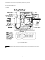
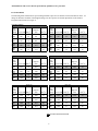
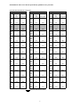
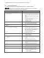
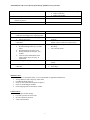
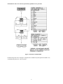
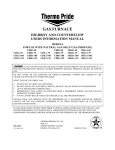
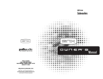
ECM OPERATION MANUAL
FOR USE WITH MODELS:
CHX1-75N
CHX1-100N
CHX1-125N
CDX1-75N
CDX1-100N
CDX1-125N
: IF YOU DO NOT FOLLOW THE SAFETY PRECAUTIONS BELOW AND IN THIS MANUAL, A
FIRE OR EXPLOSION MAY RESULT CAUSING PROPERTY DAMAGE, PERSONAL INJURY, OR LOSS OF
LIFE.
DO NOT STORE OR USE GASOLINE OR OTHER FLAMMABLE VAPORS AND LIQUIDS IN THE VICINITY OF
THIS OR ANY OTHER APPLIANCE.
WHAT TO DO IF YOU SMELL GAS:
•
•
•
•
•
DO NOT TRY TO LIGHT ANY APPLIANCE.
DO NOT TOUCH ANY ELECTRICAL SWITCH; DO NOT USE ANY PHONE IN YOUR BUILDING.
LEAVE THE BUILDING IMMEDIATELY.
IMMEDIATELY CALL YOUR GAS SUPPLIER FROM A NEIGHBOR’S PHONE. FOLLOW THE GAS
SUPPLIER’S INSTRUCTIONS.
IF YOU CANNOT REACH YOUR GAS SUPPLIER; CALL THE FIRE DEPARTMENT.
INSTALLATION AND SERVICE MUST BE PERFORMED BY A QUALIFIED INSTALLER, SERVICE AGENCY OR
THE GAS SUPPLIER. (REFERRED TO IN THESE INSTRUCTIONS AS A QUALIFIED HEATING
CONTRACTOR).
PLEASE READ THESE INSTRUCTIONS PRIOR TO INSTALLATION, INITIAL FIRING, AND BEFORE
PERFORMING ANY SERVICE OR MAINTENANCE. THESE INSTRUCTIONS MUST BE LEFT WITH THE
HOMEOWNER AND SHOULD BE RETAINED FOR FUTURE REFERENCE BY QUALIFIED SERVICE
PERSONNEL.
THERMO PRODUCTS, LLC.
BOX 217
NORTH JUDSON, IN 46366
PHONE: (574) 896-2133
MADE IN USA
MG-1018
ECN4547-MA
All installations and services must be performed by qualified service personnel.
INDEX
BEGINNING PAGE
SECTION
I.
FURNACE SPECIFICTIONS (SHIPPED SETTINGS)
1
II.
BLOWER INFORMATION
A. WIRING
B. CFM TABLES
3
3
4
III.
ECM TROUBLESHOOTING
A. GENERAL GUIDELINES TO TROUBLESHOOTING GE ECM
B. TROUBLESHOOTING CHARTS
6
6
9
i
All installations and services must be performed by qualified service personnel.
I. FURNACE SPECIFICATIONS (SHIPPED SETTINGS)
CHX1 SERIES
MODEL NO.
HEAT INPUT RATE IN BTU/HR
(High fire/ Low fire)
HEATING CAPACITY IN BTU/HR
(High fire/ Low fire)
HEIGHT OF CASING
WIDTH OF CASING
DEPTH OF CASING
WARM AIR OUTLET
RETURN AIR INLET
DIA. OF FLUE
DIA. OF COMBUSTION
AIR INTAKE
FLOWRATE from .2” & .5” w.c.
EXTERNAL STATIC PRESSURE
@COOLING TAP A (CFM)
@COOLING TAP B (CFM)
@COOLING TAP C (CFM)
@COOLING TAP D (CFM)
@HEATING TAP A
(CFM @High fire/Low fire)
TEMPERATURE RISE (°F)
BLOWER MOTOR HP
CHX1-75
CHX1-100
CHX1-125
75,000 / 52,000
100,000 / 70,000
125,000 / 87,500
70,875 / 49,612
94,500 / 66,150
117,500 / 82,250
44-1/4”
17”
27-1/2”
15 x 18
25 x 16
44-1/4”
21”
27-1/2”
19 x 18
25 x 16
44-1/4”
24”
27-1/2”
22 x 18
25 x 16
2”
3”
3”
2”
3”
3”
COOLING
COOLING
COOLING
1000
800
1200
1400
1200
1000
1400
1600
1400
1200
1600
2000
HEATING
HEATING
HEATING
931 / 760
1243 / 1015
1556 / 1270
70 / 60
.5
70 / 60
.75
70 / 60
1
2.65 Mh
2.1 Mh
POWER CHOKES
LARGEST RECOMMENDED
3.5 Ton
4 Ton
5 Ton
AIR CONDITIONER
24-3/4” x 15-3/4” 24-3/4” x 15-3/4” 24-3/4” x 19-3/4”
SIZE OF FILTERS
NOTES:
1. Heating capacity based on annual fuel utilization efficiency rated by manufacturer.
2. On all outlet and inlet dimensions, the first dimension is width.
3. To permit largest recommended air conditioning (at .5 static pressure), selection of the highest motor speed is
required.
4. Electrical characteristics at 115 volts, 60 Hz., 1 phase (less than 15 amps, for all models).
5. All specifications are subject to change without notice.
1
All installations and services must be performed by qualified service personnel.
CDX1 SERIES
MODEL NO.
HEATING INPUT RATE IN BTU/HR
(High fire / Low fire)
HEATING CAPACITY IN BTU/HR
(High fire / Low fire)
HEIGHT OF CASING
WIDTH OF CASING
DEPTH OF CASING
WARM AIR OUTLET
RETURN AIR INLET
DIA. OF FLUE
DIA. OF COMBUSTION
AIR INTAKE
FLOWRATE from .2” & .5” w.c.
EXTERNAL STATIC PRESSURE
@COOLING TAP A (CFM)
@COOLING TAP B (CFM)
@COOLING TAP C (CFM)
@COOLING TAP D (CFM)
@HEATING TAP C
(CFM @ High fire / Low fire)
TEMPERATURE RISE (°F)
BLOWER MOTOR HP
CDX1-75
CDX1-100
CDX1-125
75,000 / 56,250
100,000 / 75,000
125,000 / 93,750
69,750 / 52,312
93,000 / 69,750
116,250 / 87,187
46-1/4”
17”
27-1/2”
15 x 18
15 x 22
46-1/4”
21”
27-1/2”
19 x 18
19 x 22
46-1/4”
24”
27-1/2”
22 x 18
22 x 22
2”
3”
3”
2”
3”
3”
COOLING
COOLING
COOLING
1000
800
1200
1400
1200
1000
1400
1600
1400
1200
1600
2000
HEATING
HEATING
HEATING
1012 / 826
1340 / 1094
1673 / 1366
65 / 60
.5
65 / 60
.75
65 / 60
1
2.65Mh
2.1Mh
POWER CHOKES
LARGEST RECOMMENDED
3.5 Ton
4 Ton
5 Ton
AIR CONDITIONER
21-3/4” x 14”(2) 21-3/4” x 14”(2) 21-3/4” x 14”(2)
SIZE OF FILTERS
NOTES:
1. Heating capacity based on annual fuel utilization efficiency rated by manufacturer.
2. On all outlet and inlet dimensions, the first dimension is width.
3. To permit largest recommended air conditioning (at .5 static pressure), selection of the highest motor speed is
required.
4. Electrical characteristics at 115 volts, 60 Hz., 1 phase (less than 15 amps. for all models).
5. All specifications are subject to change without notice.
2
All installations and services must be performed by qualified service personnel.
II. BLOWER INFORMATION
A. WIRING
Figure 1: BLOWER WIRING
: TURN OFF THE ELECTRICAL POWER to the furnace before attempting to disconnect blower
wiring.
3
All installations and services must be performed by qualified service personnel.
B. CFM TABLES
The following tables contain blower speed settings and their respective air flowrates for the ECM blower motor. To
change air flowrates from that of the shipped settings, use the respective S3 and S4 dipswitches on the furnace’s
integrated control board (see Figure 1).
HEATING SPEEDS
CDX1-75
Dip
switch
settings Low fire CFM Rise (oF)
CHX1-75
High Fire
CFM
Rise (oF)
Dip
switch
settings Low fire CFM
Rise (oF)
High Fire
CFM
Rise (oF)
7-OFF
8-OFF
760
64
931
70
7-OFF
8-OFF
760
60
931
70
7-ON
8-OFF
708
69
867
75
7-ON
8-OFF
708
65
867
75
7-OFF
8-ON
826
59
1012
65
7-OFF
8-ON
826
55
1012
65
7-ON
8-ON
909
54
1114
59
7-ON
8-ON
909
50
1114
59
Rise (oF)
High Fire
CFM
Rise (oF)
60
1243
70
64
1160
75
56
1340
65
51
1450
60
Rise (oF)
High Fire
CFM
Rise (oF)
60
1556
70
64
1452
75
56
1673
65
51
1813
60
CDX1-100
Dip
switch
settings Low fire CFM Rise (oF)
7-OFF
8-OFF
1015
64
7-ON
8-OFF
947
69
7-OFF
8-ON
1094
60
7-ON
8-ON
1184
55
CHX1-100
High Fire
CFM
Rise (oF)
1243
70
1160
75
1340
65
1450
60
Dip
switch
settings Low fire CFM
7-OFF
8-OFF
1015
7-ON
8-OFF
947
7-OFF
8-ON
1094
7-ON
8-ON
1184
CDX1-125
Dip
switch
settings Low fire CFM Rise (oF)
7-OFF
8-OFF
1270
64
7-ON
8-OFF
1185
69
7-OFF
8-ON
1366
60
7-ON
8-ON
1480
55
CHX1-125
High Fire
CFM
Rise (oF)
1556
70
1452
75
1673
65
1813
60
Dip
switch
settings Low fire CFM
7-OFF
8-OFF
1270
7-ON
8-OFF
1185
7-OFF
8-ON
1366
7-ON
8-ON
1480
=FACTORY SHIPPED SETTINGS
4
All installations and services must be performed by qualified service personnel.
COOLING AND CONTINUOUS FAN SPEEDS
CDX1-75 & CHX1-75
CDX1-100 & CHX1-100
CDX1-125 & CHX1-125
Continuous
Dip
fan
switch
CFM
Cooling CFM
setting
Continuous
Dip
fan
switch
CFM
Cooling CFM
setting
Continuous
Dip
fan
switch
CFM
Cooling CFM
setting
1-OFF
2-OFF
3-ON
4-OFF
1150
1-OFF
2-OFF
3-ON
4-OFF
1380
1-OFF
2-OFF
3-ON
4-OFF
700
1610
1000
1-OFF
2-OFF
3-OFF
4-OFF
1200
1-OFF
2-OFF
3-OFF
4-OFF
700
1400
850
1-OFF
2-OFF
3-OFF
4-ON
1020
1-OFF
2-OFF
3-OFF
4-ON
700
1190
920
1-ON
2-OFF
3-ON
4-OFF
1150
1-ON
2-OFF
3-ON
4-OFF
600
1380
800
1-ON
2-OFF
3-OFF
4-OFF
1000
1-ON
2-OFF
3-OFF
4-OFF
600
1200
680
1-ON
2-OFF
3-OFF
4-ON
850
1-ON
2-OFF
3-OFF
4-ON
600
1020
1380
1-OFF
2-ON
3-ON
4-OFF
1610
1-OFF
2-ON
3-ON
4-OFF
800
1840
1200
1-OFF
2-ON
3-OFF
4-OFF
1400
1-OFF
2-ON
3-OFF
4-OFF
800
1600
1020
1-OFF
2-ON
3-OFF
4-ON
1190
1-OFF
2-ON
3-OFF
4-ON
800
1360
1600
1-ON
2-ON
3-ON
4-OFF
1700
1-ON
2-ON
3-ON
4-OFF
1000
2300
1400
1-ON
2-ON
3-OFF
4-OFF
1600
1-ON
2-ON
3-OFF
4-OFF
1000
2000
1190
1-ON
2-ON
3-OFF
4-ON
1360
1-ON
2-ON
3-OFF
4-ON
1000
1700
1-OFF
2-OFF
3-OFF
4-OFF
1-OFF
2-OFF
3-OFF
4-ON
1-ON
2-OFF
3-ON
4-OFF
1-ON
2-OFF
3-OFF
4-OFF
1-ON
2-OFF
3-OFF
4-ON
1-OFF
2-ON
3-ON
4-OFF
1-OFF
2-ON
3-OFF
4-OFF
1-OFF
2-ON
3-OFF
4-ON
1-ON
2-ON
3-ON
4-OFF
1-ON
2-ON
3-OFF
4-OFF
1-ON
2-ON
3-OFF
4-ON
500
500
500
400
400
400
600
600
600
700
700
700
600
600
600
500
500
500
700
700
700
800
800
800
=FACTORY SHIPPED SETTINGS
5
All installations and services must be performed by qualified service personnel.
III.
ECM TROUBLE SHOOTING
A. GENERAL GUIDELINES TO TROUBLESHOOTING GE ECM – DRIVEN SYSTEMS
: Disconnect power from unit before removing or replacing connectors, or servicing motor.
Wait at least 5 minutes after disconnecting power before opening motor.
SYMPTOM
Motor rocks slightly when starting
Motor won’t start
• No movement
•
•
•
•
•
•
•
•
•
•
•
•
•
•
Motor rocks, but won’t start
Motor oscillates up & down while being tested off
of blower
Motor starts, but runs erratically
• Varies up and down or intermittent
•
•
•
•
“Hunts” or “puffs” at high CFM (speed)
•
•
•
•
Stays at low CFM despite system call for cool or
heat CFM
•
•
•
Stays at high CFM
•
Blower won’t shut off
•
•
•
•
•
•
Excessive noise
•
•
•
•
Noisy blower or cabinet
6
CAUSE/PROCEDURE
This is normal start-up for ECM
Check power at motor
Check low voltage (24 VAC R to C) at motor
Check low voltage connections (G,Y,W,R,C,) at
motor
Check for unseated pins in connectors on motor
harness
Test with a temporary jumper between R – G
Check motor for tight shaft
Perform motor/control replacement check
Run Moisture Check
Check for loose or compliant motor mount
Make sure blower wheel is tight on shaft
Perform motor/control replacement check
It is normal for motor to oscillate with no load on
shaft.
Check line voltage for variation or “sag”
Check low voltage connections (G,Y,W,R,C,) at
motor, unseated pins in motor harness connectors
Check “Bk” for erratic CFM command (in
variable speed applications)
Check-out system controls – T’stat?
Perform Moisture Check
Does removing panel or filter reduce “puffing”?
! Reduce restriction
! Reduce max airflow
Check low voltage (T’stat) wires and connections
Verify fan is not in delay mode – wait until delay
complete
“R” missing/not connected at motor
Perform motor/control replacement check
“R” missing/not connected at motor
Is fan in delay mode? – wait until delay time
complete
Perform motor/control replacement check
Current leakage from controls into G,Y or W?
Check for Triac switched t’stat or solid state relay
Determine if it’s air noise, cabinet, duct or motor
noise – interview customer, if necessary
Check for loose blower housing, panels, etc.
High static creating high blower speed?
! Check for air whistling thru seams in ducts,
cabinets or panels
! Check for cabinet/duct deformation
All installations and services must be performed by qualified service personnel.
•
“Hunts” or “puffs” at high CFM (speed)
Evidence of Moisture
• Motor failure or malfunction has occurred and
moisture is present
• Evidence of moisture present inside air mover
•
•
•
•
•
•
DO
Check-out motor, controls, wiring and
connections thoroughly before replacing motor
Orient connectors down so water can’t get in
! Install “drip loops”
Use authorized motor and control model #’s for
replacement
Keep static pressure to a minimum:
! Recommend high efficiency, low static
filters
! Recommend keeping filters clean
! Design ductwork for min static, max
comfort
! Look for and recommend ductwork
improvement, where necessary, in
replacement
Size the equipment wisely
•
Does removing panel or filter reduce “puffing”?
! Reduce restriction
! Reduce max airflow
•
Replace motor and perform Moisture Check
•
Perform Moisture Check
•
DON’T
Automatically assume the motor is bad.
•
•
•
•
•
•
•
Check orientation before inserting motor
connectors
Locate connectors above 7 and 4 o’clock
positions
Replace one motor or control model # with
another (unless an authorized replacement)
Use high pressure drop filters – some have ½”
H2O drop!
Use restricted returns
Oversize system then compensate with low
airflow
Plug in power connector backwards
Force plugs
Moisture Check
• Connectors are orientated “down” (or as recommended by equipment manufacturer)
• Arrange harnesses with “drip loop” under motor
• Is condensate drain plugged?
• Check for low airflow (too much latent capacity)
• Check for undercharged condition
• Check and plug leaks in return ducts, cabinet
Comfort Check
• Check proper airflow settings
• Low static pressure for lowest noise
• Set low continuous-fan CFM
• T’stat in bad location?
7
All installations and services must be performed by qualified service personnel.
Figure 2: ECM PIN CONNECTORS
Troubleshooting table above and Figure 2 adapted from GE Industrial Systems publication GED-7161C,
“Troubleshooting GE ECM – Driven Systems”.
8
All installations and services must be performed by qualified service personnel.
B. TROUBLESHOOTING CHARTS
THIS GUIDE SHOULD BE USED IN THE CASE OF A STOPPED OR MANFUNCTIONED ECM
BLOWER MOTOR. THE FOLLOWING SHOULD HELP ESTABLISH THE TYPE OF
MALFUNCTION OR DEVIATION FROM THE NORMAL BLOWER OPERATION.
TO USE THIS DIAGRAM, YOU JUST NEED TO FOLLOW THE INSTRUCTIONS IN THE BOXES.
CONFIRM IF EITHER BLOWER
WHEEL IS RUBBING AGAINST
HOUSING OR MOTOR SHAFT
IS SPINNING FREELY, REPAIR
OR REPLACE AS NECESSARY.
NO
DOES BLOWER SPIN FREELY?
YES
CHECK 115V SUPPLY,
CONNECTION FUSES,
SERVICE SWITCH AND
DOOR SWITCH.
NO
IS THERE 115V
SUPPLIED TO MOTOR?
YES
DISCONNECT 16 PIN
HARNESS FROM
MOTOR. IS THERE 24V
ACROSS PIN12 & PIN1
AND PIN12 & PIN3
AT THE HARNESS PLUG?
IS THERE 24V
ACROSS R &
B/C ON THE
INTEGRATED
CONTROL?
NO
NO
CHECK 24V SUPPLY
TO INTEGRATED CONTROL.
NO
REPLACE
INTEGRATED
CONTROL.
YES
YES
DISCONNECT 16PIN
HARNESS FROM
INTEGRATED CONTROL.
IS THERE 24V ACROSS
PIN12 & PIN1 AND
PIN12 & PIN3
AT THE CONROL?
YES
CHECK HARNESS
CONNECTIONS
AND WIRE.
TURN THERMOSTAT MANUAL FAN
SWITCH ON (IF AVAILABLE) OR JUMPER
BETWEEN R & G ON INTEGRATED CONTROL.
IS THERE VOLTAGE GREATER THAN
12V BETWEEN PIN15 & PIN1?
NO
YES
CHECK CONNECTION ON HARNESS AND MOTOR,
RECONNECT HARNESS TO MOTOR, IF
CONNECTIONS ARE GOOD AND MOTOR STILL
DOES NOT RUN REPLACE MOTOR.
9
CHECK CONNECTIONS AND WIRES
AT INTEGRATED CONTROL, IF OK
REPLACE INTEGRATED CONTROL.