1
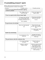
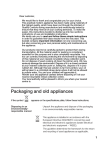
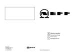
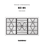
INSTALLATION INSTRUCTIONS AND
USE AND MAINTENANCE RECOMMENDATIONS
FOR GAS HOBS
EINBAUANLEITUNG FÜR GAS-GLASKOCHFELDER MIT BEDIENUNGS- UND PFLEGEHINWEISEN
INSTRUCTIONS POUR L'INSTALLATION ET RECOMMANDATIONS D'UTILISATION ET DE MAINTENANCE
DES CUISINIÈRES À GAZ
CGX 60 4G IS - CGX 70 5G IS TR
Índice / Inhalt / Table des matières /
DE
GB
Introduction
User Guide
4
5
Allgemeines
Bedienungshinweise
4
21
Installation
Positioning the hobs
Positioning the oven
Fixing the hob
Connecting the gas
Connecting the electricity
Gas conversion
6
6
7
7
7
8
8
Einbau
Einbau des Kochfelds
Einbau des Herdes
Verankerung
Gasanschluss
Netzanschluss
Umrüstung auf eine andere Gasart
22
22
23
23
23
24
24
Technical Information
Dimensions and powers
Technical data
10
10
11
Technische Angaben
Abmessungen und Leistung
Technische Daten
26
26
27
Use and Maintenance
Special requirements before first use
Component parts of a gas burner
Touch control panel user instructions
Locking the sensor buttons of the
hob
Safety disconnection
Safety against overheating
Mechanism to protect against
inadvertently turning the gas
control knobs
Component parts of an automatic
control and safety system
Using the hob
Tips for correctly using burners
Reminder
Cleaning and care
Maintenance
12
12
12
12
Bedienung und Pflege
Maßnahmen vor Inbetriebnahme
Brenneraufbau
Sensorbedienung
Sensor-Kindersicherung
Sicherheitsabschaltung
Überhitzungsschutz
Mechanische Knebelsperre
Thermoelektrische Zündsicherung
Gebrauch des Kochfelds
Hinweise zur sachgemäßen
Bedienung der Brenner
Wichtige Hinweise
Reinigung und Pflege
Wartung
28
28
28
28
30
30
30
31
31
32
Störungsbehebung
36
If something doesn't work
20
2
14
14
14
15
15
16
16
17
18
19
32
33
34
35
FR
Présentation
Guide d'utilisation
4
37
Installation
Emplacement des plans de travail
de cuisson
Emplacement du four
Ancrage du plan de travail de cuisson
Connexion du gaz
Connexion électrique
Transformation du gaz
38
Information technique
Dimensions et puissances
Données techniques
42
42
43
Utilisation et Maintenance
Conditions particulières avant la
mise en service
Éléments d'un brûleur
Instructions d'utilisation de la
commande tactile
Blocage des capteurs du
plan de travail de cuisson
Déconnexion de sécurité
Sécurité de surchauffes
Système anti-ouverture
accidentelle des
commandes de gaz
Composants d'un système
automatique de contrôle et de
sécurité
Utilisation de la cuisinière
Conseils pour la bonne utilisation
des brûleurs
Rappel
Nettoyage et conservation
Maintenance
44
38
39
39
39
40
40
44
44
44
46
46
46
47
47
48
48
50
51
52
Si quelque chose ne fonctionne pas 53
3
Introduction / Allgemeines / Présentation /
Παρουσίαση
2
1
2
1
5
3
6
5
CGX 70 5G IS TR
CGX 60 4G IS
GB 1 2,580 Kcal/h - 3 Kw fast burner.
GB
1 2,580 Kcal/h - 3 Kw fast burner.
2 1,500 Kcal/h - 1.75 Kw semi-fast burner.
3 1,500 Kcal/h - 1.75 Kw semi-fast burner.
4 860 Kcal/h - 1 Kw auxiliary burner.
5 3,010 Kcal/h - 3.5 Kw triple ring burner.
6 Burner control knobs.
* All burners incorporate a pan support.
* Maximum heat output: 9,450 Kcal/h - 11 Kw.
* Maximum electrical power: 4 W.
DE
1 Starkbrenner 2 580 Kcal/h - 3 kW
2 Normalbrenner 1 500 Kcal/h - 1,75 kW
3 Normalbrenner 1 500 Kcal/h - 1,75 kW
4 Hilfsbrenner 860 Kcal/h - 1 kW
5 Dreifachbrenner 3 010 Kcal/h - 3,5 kW
6 Knebel
* Alle Brenner verfügen über einen Topfträgerrost.
* Maximale Wärmeleistung: 9 450 Kcal/h - 11 kW
* Maximale elektrische Leistung: 4 W
FR
1 Brûleur rapide de 2 580 Kcal/h - 3 kW.
2 Brûleur semi-rapide de 1 500 Kcal/h - 1,75 kW.
3 Brûleur semi-rapide de 1 500 Kcal/h - 1,75 kW.
4 Brûleur auxiliaire de 860 Kcal/h - 1 kW.
5 Brûleur triple couronne de 3 010 Kcal/h - 3,5 kW.
6 Commandes de mise en marche des brûleurs.
* Tous les brûleurs ont une grille.
* Puissance calorifique maximum : 9 450 Kcal/h - 11
kW.
* Puissance électrique maximum 4 W.
2 1,500 Kcal/h - 1.75 Kw semi-fast burner.
3 1,500 Kcal/h - 1.75 Kw semi-fast burner.
4 860 Kcal/h - 1 Kw auxiliary burner.
5 Burner control knobs.
* All burners incorporate a pan support.
* Maximum heat output: 6,450 Kcal/h - 7.5 Kw.
* Maximum electrical power: 4 W.
DE 1 Starkbrenner 2 580 Kcal/h - 3 kW
2 Normalbrenner 1 500 Kcal/h - 1,75 kW
3 Normalbrenner 1 500 Kcal/h - 1,75 kW
4 Hilfsbrenner 860 Kcal/h - 1 kW
5 Knebel
* Alle Brenner sind mit einem Rost ausgestattet.
* Maximale Wärmeleistung: 6 450 Kcal/h - 7,5 kW
* Maximale elektrische Leistung: 4 W
FR
1 Brûleur rapide de 2 580 Kcal/h - 3 Kw.
2 Brûleur semi-rapide de 1 500 Kcal/h - 1,75 kW.
3 Brûleur semi-rapide de 1 500 Kcal/h - 1,75 kW.
4 Brûleur auxiliaire de 860 Kcal/h - 1 kW
5 Commandes de mise en marche des brûleurs.
* Tous les brûleurs ont une grille.
* Puissance calorifique maximum : 6.450 Kcal/h - 7,5
kW.
* Puissance électrique maximum 4 W.
GR
GR
4
4
3
4
Guide to Using the Instructions Booklet
Dear Customer,
Safety Instructions
We are delighted that you have put your
trust in us.
Before first use, you should carefully read
the installation and connection instructions.
We are confident that the new hob that
you have purchased will fully satisfy your
needs.
This modern, functional and practical
model has been manufactured using topquality materials that have undergone
strict quality controls throughout the
manufacturing process.
Before installing and using it, please read
this Manual carefully and follow the instructions closely; this will guarantee better
results when using the appliance.
Keep this Instruction Manual in a safe
place so that you can refer to it easily and
thus abide by the Guarantee conditions.
These hob models may be installed in the
same kitchen furniture units as TEKA
brand ovens.
For your safety, installation should be
carried out by an authorised technician
and should comply with existing installation standards. Likewise, any internal work
on the hob should only be done by TEKA's
technical staff, including replacing the
mains cable.
Attention:
When the burners are being used
or have recently been used, some
areas will be hot and can burn. Children
should be kept well away.
In order to benefit from this Guarantee, it is
essential that you submit the purchase
receipt together with the Guarantee certificate.
You should keep the Guarantee
Certificate or, where relevant, the technical datasheet, together with the
Instruction Manual for the duration of
the useful life of the appliance. It contains important technical information.
5
GB
Installation
Important
Minimum distance
to walls
fig. 1
INSTALLATION AND SETUP SHOULD
BE CARRIED OUT BY AN AUTHORISED
TECHNICIAN
ACCORDING
TO
CURRENT INSTALLATION STANDARDS.
Positioning the hobs
Depending on the model to be installed, an
opening with the dimensions shown in
figure 1 should be cut into the unit's worktop.
Minimum ventilation
distances
The system for fixing the hob is intended
for use with kitchen units with a thickness
of 20, 30 and 40 mm.
A shelf should be placed inside the kitchen
unit; there should be a minimum distance
of 20 mm between the lower part of the
hob and the upper part of the shelf.
The hobs described in this manual can
only be installed with TEKA brand ovens.
Fitting holes
57
5m
The minimum distance between the cookware support surface and the lower part of
the kitchen unit or the hood located above
the hob should be at least 650 mm. If the
hood's installation instructions recommend
that the distance is greater than this, you
should follow this advice.
ax
.
W
L
57
5m
ax
.
The unit where the hob and oven will be
located should be suitably fixed.
W
Warnings:
L
When hobs are handled before
being installed, care should be taken in
case there is any protruding part or
sharp edge which could cause injury.
When installing units or appliances above the hob, the hob should be
protected by a board so that the glass
6
Mod.: CGX 60 4G IS
Mod.: CGX 70 5G IS TR
The dimensions L and W are in the table
"Dimensions and characteristics" in the Technical
Information section.
GB
cannot be damaged by accidental
blows or heavy weight.
fig. 2
If the glass breaks or cracks, the
hob should immediately be disconnected from the electric current in order to
avoid the risk of electric shock.
The glues used in manufacturing
the kitchen unit and on the decorative
laminates and on the laminates that are
part of the worktop surface should be
made to tolerate temperatures of up to
100ºC.
TEKA does not assume any responsibility for any malfunction or
damage caused by faulty installation.
PLEASE REMEMBER THAT THE GUARANTEE DOES NOT COVER THE
GLASS IF IT SUFFERS A VIOLENT
BLOW OR IF IT IS USED IMPROPERLY.
Positioning the oven
Please see the corresponding
manual.
Fixing the hob
When the gap has been properly sized,
the gasket (A) should be put on the lower
side of the hob. Place the clips (D) as indicated in figure 2, fastening them to the
holes of the lower part of the body by using
the self-tapping screws provided (Ø 4,2
mm).
If the thickness of the kitchen unit is equal
to or less than 30 mm, use the self-tapping
screws that are provided as a fastening
accessory by putting them into the clip's
round hole. This hole will be threaded as
the screw is inserted into it, which should
be done before fixing the clip to the hob.
20 mm
30 mm
40 mm
Gasket
Hob
Screw
Clip
Note: It is essential that the gasket be
placed under the brim of the hob.
Failure to install it may cause the worktop to be exposed to high temperatures.
Connecting the gas
The gas exit pipe of the hob should be
connected to the gas mains according to
installation standards or regulations in
force and it should be done by qualified
technical staff (an authorised installer).
Since it is an immobilised appliance, the
gas connection for these hobs must be
done using rigid piping for hobs to be used
in the EC. The hob comes with a ½" diameter threaded connection as per EN ISO
228-1 or a ½" taper threaded connection
as per EN 10226-1, in accordance with the
regulations of the country where the hob is
to be used.
The gas exit pipe of the hob should be
connected to the gas mains following
basic guidelines for the installation of gas
in inhabited buildings
TEKA does not assume any responsibility
for any malfunction or damage caused by
incorrect or faulty installation.
To avoid damaging the hob when tighte7
GB
ning the gas pipe connection nut, a maximum grip torque of 300 cm * Kgf should be
used.
Once the gas connection has been carried
out, check that it is properly tightened. If
this is done using air, please remember
that the test pressure should not be greater than 200 g/cm². If you do not have air,
use soapy water to make sure that there
are no leaks in the joints. It is absolutely
unadvisable to carry out this check using a
flame.
Once the hob has been installed, make
sure that the minimums of the burners are
properly adjusted. To do so, light the burners and check that they do not turn off
when turned quickly from the maximum to
the minimum.
Every time that the gas connection nut is
removed, the washer should be changed.
Connecting the electricity
Before connecting the hob to the electric
mains, check that the voltage and frequency of the mains matches what is
shown on the hob's rating plate, which is
located on the lower part of the hob, and
on the guarantee or, where appropriate,
the technical data sheet supplied, which
should be kept together with this manual
during the useful life of this appliance.
The electric connection is made using an
omnipolar switch or plug, where accessible, that is suitable for the intensity to be
tolerated and that has a minimum gap of 3
mm between its contacts. This will ensure
disconnection in case of emergency or
when cleaning the hob. It should also have
a proper earthing connection, in accordance with current regulations.
The connection should include correct ear8
thing, in compliance with current norms.
If the flexible supply cable fitted to the
appliance ever needs to be changed, it
should be replaced by TEKA's official technical service.
Gas conversion
Important!
Any changes made to the appliance to
convert it to a different type of gas
should only be carried out by a qualified technician.
Information for the Technical
Service: whenever the type of gas or the
appliance's pressure is changed, the new
regulation plate should be placed on top of
the old one so that the new features can
be seen after the change.
The tasks involved in conversion are:
* Replace the injectors.
* Adjust the minimums of the taps.
The injectors required for each gas type
are shown in table 1.
Please follow these instructions to replace
the injectors:
1 Remove the pan supports and the upper
parts of the burner so that the injector
can be seen.
2 Using a number 7 pipe spanner, remove
the injectors and replace them with the
new ones. Ensure that the injector is
properly tightened in order to prevent
gas from escaping.
3 Replace the pan supports and burners
that were previously removed.
When the injectors have been changed,
adjust the minimums as follows:
1 Turn the burners on to their minimum.
GB
2 Remove the controls of the taps by
pulling firmly upward and remove the
gasket.
3 Use a slim, grooved screwdriver to turn
the screw that is next to the shaft of the
gas tap (detail "A" in figure 3).
4 When properly adjusted, check that the
flame does not go out when you turn the
knob quickly from maximum to minimum.
Table 1
TEKA INDUSTRIAL, S.A. will not accept
liability for any hob malfunction if the gas
conversion or the adjustment of the minimums of the burners has not been carried
out by TEKA's Technical Service.
Ø injector in 1/100 mm
Burner
Family
Second
Third
Group H
Group 3+
Triple ring
135 T
95
Fast
116 Y
85
Semi-fast
97 Z
66
Auxiliary
72 X
50
fig. 3
Front view of the gas tap
9
GB
Technical Information
Dimensions and powers
Models
CGX 60
4G IS
Dimensions in mm
Length
610
Width
510
Height
119
Thickness of the glass
4
Dimensions for positioning in the kitchen unit mm
553
Length
473
Width
73
Depth
Power per burner and cooking element
3.5 Kw triple ring gas burner
3 Kw fast gas burner
1
2
1.75 Kw semi-fast gas burner
1 Kw auxiliary gas burner
Electric
Nominal power (W)
Power supply
voltage (V)
Frequency (Hz)
Gas
Nominal Calorific
Consumption (kw)
710
510
127
4
660*
473
73
1
1
2
1
1
4
4
220 / 240 V.
220 / 240 V.
50
50
7,5
11
* For granite worktops, the size may be 563 mm.
10
CGX 70 5G
IS TR
GB
ventilation system device should be
installed (mechanical ventilation hood).
Technical data
COMMON FEATURES FOR ALL
MODELS WITH AUTOMATIC IGNITION
The supply voltage and frequency will be
as shown on the rating plate.
COMMON FEATURES FOR THESE GAS
MODELS
Warnings:
a) Before installation, make sure that the
local supply conditions (the gas type and
pressure) are compatible with the appliance's setup.
b) The setup conditions for this appliance
are written on the label (or the rating
plate).
c) This appliance should not be connected
to a device for removing combustion` products.
Intense and prolonged use of the
appliance require complementary ventilation, such as opening a window, or
more efficient ventilation, such as
increasing the power of the mechanical
ventilation, if there is one.
You should keep the Guarantee
Certificate or, where relevant, the
technical datasheet, together with the
Instruction Manual for the duration of
the useful life of the appliance. It contains important technical information.
Class 3 hob.
Table 2
Country
Category
Spain
II2H3+
Portugal
II2H3+
It should be installed and connected in compliance with the current installation standards. Special attention should be paid to
the regulations applying to ventilation.
United Kingdom
II2H3+
Switzerland
II2H3+
Ireland
II2H3+
Chez Republic
II2H3+
The use of a gas cooking
appliance produces heat and moisture
at the site where it is installed. The kitchen should be provided with suitable
ventilation: natural ventilation sources
should be kept clear, a window should
be opened or an effective mechanical
Greece
I3+
Hungary
I2H
Denmark
I2H
Norway
I2H
Finland
I2H
Table 3
Sweden
I2H
Rumania
II2H3B/P
Triple
ring
Burner
Nominal Heat Rate
kW
Fast
Semi-fast Auxiliary
3,5
3
1,75
1
G-20 (Nm3/h) 20 (mbar)
G-30 (Kg/h) 29 (mbar)
0,33
0,29
0,17
0,10
0,25
0,22
0,13
0,07
G-31 (Kg/h) 37 (mbar)
0,24
0,21
0,13
0,07
Reduced calorific consumption
Kw
1,55
0,77
0,47
0,33
Output
%
>52
>52
>52
–
Nominal Rate*
* Rate over Higher Heating Value (Hs )
11
GB
Use and Maintenance
Special requirements
before first use
Touch control panel user
instructions
Before connecting the hob to the electric
mains, check that the voltage and frequency of the mains matches what is
shown on the hob's rating plate, which is
located on the lower part of the hob, and
on the guarantee or, where appropriate,
the technical data sheet supplied, which
should be kept together with this manual
during the useful life of this appliance.
CONTROL PANEL ELEMENTS (see fig. 5)
This appliance is not designed to
work through an external timer (not
incorporated into the appliance itself)
or a separate remote control system.
Component parts of a gas
burner
1 On/off sensor button.
2 Burner and residual heat selection
lights.
3 Burner indicator symbols.
4 Lock function indicator symbol.
5 Indicator light of the activated locking
option.
6 Touch control panel on light.
NOTE: * Only visible when appliance is
operating.
fig. 5
Note: Every time that a burner is
assembled, please make sure that all of
the components are adjusted correctly.
fig. 4
Actions are carried out using the on/off
sensor button
(1) on the control panel
and the tap control.
It is not necessary put pressure on the glass
to use the sensor; by simply touching the
sensor button with your finger, you will activate the desired function.
Pan support
Diffuser cover
Diffuser crown
Injector
Injector holder
12
Each action is confirmed with a beep.
GB
2 Turn on the gas at the mains or turn the
gas cylinder tap.
fig. 6
3 Turn and put pressure on the burner
knob so that the gas ignites.
4 Place the knob in the desired position.
5 The burner selection light will go on.
The control panel has marked zones (A)
that indicate the control knob that corresponds to each burner.
Indicator of the burner being used
Off position
Maximum gas position
Use flat-bottomed cookware and make
sure that they sit squarely on the pan support, so that the cookware does not slip
when food boils (do not use cookware with
a concave or convex base).
Minimum gas position
TURNING ON THE APPLIANCE
Whenever you connect the hob to the
electrical mains for the first time, the lock
function will be activated. To deactivate
this function, see the section "Locking the
hob sensor".
1 Touch the on sensor button
least one second.
(1) for at
The next action must be taken within three
minutes; otherwise, the touch control panel
will automatically turn off.
IGNITING THE BURNERS
Once the touch control panel has been
activated by using the sensor button
(1), you can turn on the chosen burners.
To do so, please do as follows (see fig. 6):
1 Make sure that the knobs are in the
correct position.
If an error occurs while igniting
the burner, the burner will be deactivated after the safety time has elapsed (10
seconds).
These hobs may not be lit using
matches.
Table with diameters of cookware according to the type of
burner
Power
(in Watts)
Diameter of
cookware
(in cm)
Triple ring
3500
24 _: 26
Fast
3000
20 _: 22
Semi-fast
1750
16 _: 18
Auxiliary
1000
10 _: 14
Burner
RE-LIGHTING
If one of the burners accidentally turns off
with the tap connected (i.e. turned), the
system will automatically attempt to relight the burner for 10 seconds.
13
GB
EMERGENCY SHUT-OFF
The appliance may be turned off at any
time by touching the general on/off sensor
button
(1). After doing so, turn the control knobs back to the initial position.
TURNING OFF THE BURNER
1 Use the corresponding control knob to
lower the power to the off position (B in
fig. 6).
Once the burner has been turned off, its
light (2) will go on, which indicates that
there is residual heat, i.e. that it is still hot
and, therefore, it may cause burns.
TURNING OFF THE APPLIANCE
1 Once all of the control knobs are in the
off position (B in fig. 5), touch the general on/off sensor button
(1)
If the light of a burner (2) (see fig.
5) is flashing, it means that the control
knob should be turned again to the off
position.
Locking the sensor buttons
of the hob
If the hob is disconnected and you touch
the on/off sensor button
(1) for more
than 4.5 seconds, you will lock the burners. This will allow you to prevent undesirable operations from occurring accidentally and it will make it so children are not
able to manipulate the device. Once the
sensor button lock has been activated, the
indicator light (5) will turn on.
If you try to light a burner when this function is activated, its light (2) will flash, indicating that it is an erroneous operation.
To deactivate the lock function, touch the
14
on/off sensor button
(1) again for at least
4.5 seconds. The lock indicator light (5) will
turn off, the light (6) will stay on and it will be
possible to once again use the control
knobs.
The lock only works on the electronic system; it does not affect the
mechanical movements of the taps of
each burner. This means that, when the
lock function is activated, gas will
come out when pressing on the control
knobs.
Safety disconnection
MAXIMUM OPERATION TIME
If one or more burners are left on, they will
disconnect automatically after six hours.
Safety against overheating
The hob is protected against overheating
of the electronic system, which could
damage it.
The entire hob will turn off if the temperature of the electronic system exceeds 105º
C, and it will begin functioning again normally when the temperature decreases to
95º C.
Warnings:
You should periodically clean the
ignition unit very carefully (ceramic and
electrode) in order to prevent ignition
problems. Also make sure that the openings of the burners are not obstructed.
When the burners are being used
or have recently been used, some areas
of the hob will be hot and can burn.
Children should be kept well away.
GB
For safety reasons, we recommend that you follow the instructions
provided by the gas company when closing the supply tap when the hob is not
in use.
If the smell of gas is detected, the
hob's gas intake tap should be shut off
and the room should be ventilated. In
addition, the gas installation and the
hob should be checked by a specialised technician.
The automatic lighting device
should not be used for more than 15
seconds. If the burner does not light
during this time, stop attempting to
light it and open the door of the room
and/or wait for at least one minute before trying to light the burner again.
If the flame of the burner goes
out accidentally, close the corresponding control knob of the burner and do
not try and light the burner again for at
least one minute.
The appliance is not designed to
be used by people (including children)
with reduced physical, mental or sensory abilities. It should also not be used
by people that do not have experience
handling the appliance or who do not
have knowledge of the appliance,
unless they are supervised by a person
who is in charge of their safety.
Children should not be allowed
to play with the appliance.
Mechanism to protect
against inadvertently turning
the gas control knobs
trol knobs from turning freely from the off
position to the on position (and, therefore,
prevents gas from accidentally escaping
from the burners) if the control knob has
not previously been pressed down.
If at any time while using the hob
you notice that a control knob can be
turned from the off position without it
needing to be pressed down beforehand (for example: because of dirt
which may have got into and accumulated in the gas taps) you should, for your
own safety, quickly notify the technical
service so that the problem can be rectified.
Component parts of an
automatic control and safety
system
On these hobs with the safety feature, the
gas cut-off device is made up of the following elements:
* The safety tap
* The safety thermocouple, next to the burner.
* The thermocouple-control card connection.
* The control card-tap connection
The thermocouple sends an electric signal
to the control card, which identifies whether
or not the burner has a flame. Once the
control card has processed the data, it
sends another electric signal to the tap so
that it opens and allows gas to enter. If the
burner turns off, the absence of a flame will
be detected by the thermocouple, which,
since it is not sending a signal to the control
card, will re-light the burner (10 seconds). If
this does not work, the control card will
send a new signal to the tap to cut-off the
gas.
The gas taps are equipped with a
mechanical systems that prevents the con15
GB
fig. 7
Suggestions for using the
burners effectively
* Fast burners should not be used with
cookware that has a small diameter,
because part of the flame will spread
away from the cookware and thus reduce performance significantly. (See fig.
9).
Safety thermocouple
Thermocouple-tap connection
Connection to the sparking unit
Spark plug
Ceramic
Electrode
Safety tap
fig. 9
Bien
Mal
Using the hob
* If the glass is broken or cracked, turn all
of the control knobs of the hob to the off
position as well as the gas intake tap
and disconnect the electrical current.
Contact TEKA'S Technical Service.
* Do not keep items on the glass surface.
* Do not leave aluminium foil, tinfoil or
plastic wrap on the glass surface.
* In these five-burner models, large cookware should be placed on the central
burner in order to prevent it from reflecting heat on the kitchen unit worktop.
fig. 8
16
* The burners should not be operated
without there being cookware on them,
or gas will be wasted and the pan support will heat up excessively.
* When the burners are in operation, they
should not to be exposed to strong
draughts, because of the loss of heat
output.
* If the burner makes the cookware smoky
or if the tip of the flame is yellow, the
burner should be cleaned. If the problem
persists, you should contact the
Technical Assistance Service in order to
adjust the primary air intake or clean the
gas piping.
* Cookware placed on the burners should
not jut out past the edge of the hotplate,
because the effect of the flame being
reflected from the cookware can damage hobs with plastic surfaces.
* Use pans with a flat base.
Reminder
GB
Do not use small cookware on large burners, because the flame will spread away.
Use proper cookware for each burner in order to better utilise the heat.
Do not place cookware misaligned over the centre of
the burner.
Place the cookware properly centred over the burner.
Do not use instruments that reflect excessive heat
downward directly over the pan support.
To use griddles, clay casseroles or cookware that
reflect heat downward, use the pan support accessory.
Do not place cookware directly on the burner.
Place cookware on the pan support.
Do not use sharp object over the hob.
After using the pan supports, it is a good idea to
clean them once they have cooled.
Do not use excessive weights or bang the hob with a
heavy object.
Handle cookware with care over the hob.
17
GB
Cleaning and care
To properly care for the glass, you should
clean it with suitable products and instruments when the glass is cold. If you clean
it every time it is used, it will be easier to
clean and you will keep dirt from different
cooking sessions from getting stuck.
The degree of soiling should be taken
into account when cleaning the glass.
Please clean glass as indicated below:
* When soiling is light and does not stick, it
can be cleaned using a damp cloth and
a mild detergent.
* Heavy stains or grease stains should be
cleaned using a cleaning agent suitable
for
glass
(example:
Clen
Vitrocerámicas).
* Sticky stains that have been burned in
can be removed by using a scraper with
a razor blade.
* Plastic objects, sugar or food with a high
sugar content that are melted onto the
hob should be removed immediately
while hot by using a scraper
* Under no circumstances should you use
abrasive cleaning agents or products
that scratch, such as oven cleaning
sprays, rust stain removers or sponges
or scouring pads with a hard surface.
* Do not slide cookware over the glass;
this may cause scratching.
* Make sure that cookware is not left
without liquid. The heat accumulated in
the bottom of the cookware could cause
damage to the burner or to the hob
glass.
* The glass will withstand bangs from large
cookware that does not have sharp
edges. Please be careful with impacts
from small, sharp utensils. Do not strike
the edge of the glass with cookware as
this may cause irreparable damage to
the glass.
* Do not spill cold liquids on the glass or
the burners when they are hot.
18
* Do not stand or lean on the glass. It may
break and cause injury.
To clean and care for other components, please follow these guidelines:
* Pan supports should be cleaned with a
non-abrasive scouring pad after they
have cooled off.
* Burners should be cleaned periodically,
particularly the grooves in the burner
heads. To do so, soak them in warm,
soapy water and scrub them with a
scouring pad or with a stiff brush.
* Do not clean the enamelled burner
covers when they are still hot. Damage
can be caused by abrasive products,
such as vinegar, coffee, milk, saltwater
and tomato juice, as a result of prolonged contact with the enamelled surfaces.
* When the burners have been dismantled
for cleaning purposes, care should be
taken to prevent liquids or other objects
from entering the nozzle unit.
* Do not use cleaning products that attack
aluminium, such as caustic soda, oil,
etc.
* Every time you assemble a burner, check
that all of its component parts fit together
correctly. A badly positioned element
may cause the hob glass to overheat
* You should periodically clean the ignition
unit very carefully (ceramic and electrode) in order to prevent lighting problems.
Also make sure that the openings of the
burners are not obstructed.
GB
Maintenance
No part of this appliance requires periodic
lubrication.
The burners are operating correctly when
they have a blue-green, stable flame. If the
tips of the flame are yellow, the burners
should be cleaned thoroughly. If the problem persists, contact the Technical
Service. To ensure that the gas installation
is properly sealed and that the burners
continue to work correctly, the hob must be
serviced by the Specialised Technical
Service at least once every year.
Note:
The symbol
on the product or on
its packaging indicates that this product may not be treated as household
waste. Instead, it should be handed
over to the applicable collection point
for the recycling of electrical and electronic equipment. By ensuring that this
product is disposed of correctly, you
will help prevent potential negative
consequences for the environment and
human health which could occur if this
product is not handled correctly. For
more detailed information on the recycling of this product, please contact
your local city office, your household
waste disposal service or the shop
where you purchased the product.
Any necessary alternation or set-up of
the appliance must be carried out by
authorised technical staff.
19
GB
If something doesn't work
Before calling the Technical Service, please check
the following possible causes and solutions:
Problem
Possible cause
There is no spark when the automatic lighting
control is pressed
The voltage does not
reach the plug
Possible solution
Check and repair the
power mains
There is a spark but the burner doesn't light
The spark plug and the
part of the burner where
the spark should be is soiled or greasy
Clean the end of the
spark plug and the
burner
Gas is not reaching the
hob
Check that the gas
cylinder tap is properly
open
The gas burners do not light
If it is piped gas, open
the gas tap
Sparks fly occasionally
Low adjustment of the
minimum
Increase the flow by
adjusting the minimum
of the tap
The gas burners make the cookware dirty
20
The burner openings
are dirty
Clean the burner
openings
Injector or injector
holder is dirty
Clean the injector holder
and injector without
using anything which
could damage or alter
the diameter of the gas
outlet opening