1
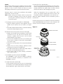
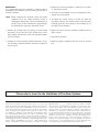
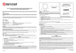
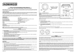
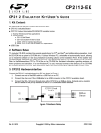
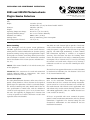
INSTALLATION AND MAINTENANCE INSTRUCTIONS
2451 and 2451TH Photoelectronic
Plug-in Smoke Detectors
Specifications
Size
Height:
Diameter:
Weight:
Operating Temperature Range:
Operating Humidity Range:
Maximum Air Velocity:
Locking Alarm:
Fixed Temperature Thermal:
2.4 inches (61 cm)
Add 0.5 inches (13 cm) for thermal model 2451TH
4.0 inches (101 cm)
0.5 lb. (277 g)
0°C to 49°C (32°F to 120°F)
10% to 93% Relative Humidity
3000 Ft./Min. (15 M/S)
Reset by momentary power interruption
135°F (57°C)
Before Installing
Please thoroughly read the System Sensor publication,
A05-1003, Applications Guide for System Smoke Detectors,
which provides detailed information on detector spacing,
placement, zoning, wiring, and special applications. Copies
of this guide are available at no charge from System Sensor.
(For installations in Canada, refer to CAN4-S524, Standard
for the Installation of Fire Alarm Systems and CEC Part 1,
Sec. 32.)
Two LEDs on each detector light to provide a local 360°
visible alarm indication. They flash every ten seconds indicating that power is applied and the detector is operating
properly. The LEDs light continuously in alarm. Remote
LED annunciator capability is available as an optional
accessory. These detectors also have the Latching Alarm
feature. The alarm can be reset only by a momentary power
interruption. These detectors may be tested by activating
the internal reed switch with a magnet, or by inserting a
calibrated test card in a test slot after removing the detector cover.
NOTICE: This manual should be left with the owner/user
of this equipment.
The 2451 has been approved for marine use in dry locations
by Underwriters Laboratory, Inc. The detector is to be used
in dry interior locations only.
IMPORTANT: This sensor must be tested and maintained
regularly following NFPA 72 requirements. This sensor
should be cleaned at least once a year.
General Description
The 2451 photoelectronic detectors utilize state-of-the-art,
optical sensing chambers. These detectors are designed to
provide open area protection, and to be used with compatible UL-listed control panels only. Model 2451TH has the
same specifications as Model 2451, with the addition of
a built-in fixed temperature (135°F–57°C) thermal detection unit. The capability of plugging these detectors into
a variety of special bases makes them more versatile than
equivalent direct-wired models.
D400-02-01
3825 Ohio Avenue, St. Charles, Illinois 60174
1-800-SENSOR2, FAX: 630-377-6495
www.systemsensor.com
Base Selection and Wiring Guide
Refer to the installation instructions for the Plug-in
Detector Bases for base selection and wiring instructions.
System Sensor has a variety of detector bases available for
this smoke detector. This includes 2-wire applications with
and without relays and/or current limiting resistors, 4-wire
and 120VAC applications. (Note: the 120VAC detector base
is not available in Canada.)
All bases are provided with screw terminals for power,
ground, remote annunciator connections and relay contact
connections, if applicable. The electrical ratings for each
detector-base combination are also included in the base
installation instructions.
1
I56-277-10R
Installation
NOTE: Wiring must conform to applicable local codes,
ordinances, and regulations.
3. After all detectors have been installed, apply power to
the control unit.
4. Test the detector using the magnet or the test card as
described under TESTING.
NOTE: Verify that all detector bases are installed, that
the initiating-device circuits have been tested, and
that the wiring is correct. (Refer to detector base
manual for testing procedure.)
5. Reset the detector at the system control panel.
6. Notify the proper authorities that the system is back on
line.
WARNING
Disconnect power from initiating-device circuits before
installing detectors.
CAUTION
Dust covers can be used to help limit dust entry to the
detector, but they are not a substitute for removing the
detector during building construction. Remove any dust
covers before placing system in service.
1. Install detectors:
a. Place the detector into the detector base
b. Turn the detector clockwise until the detector drops
into place.
c. Continue turning detector clockwise to lock it in
place.
CAUTION
Smoke detectors are not to be used with detector guards
unless the combination has been evaluated and found
suitable for that purpose.
2. Tamper-Resistance: This detector includes a tamperresistant feature that prevents removal of the detector
without the use of a tool. To make the detector tamperresistant, break off the smaller tab at the scribed line
on the tamper-resistant tab, on the detector mounting
bracket, then install the detector. To remove the detector
from the bracket once it has been made tamper-resistant,
use a pocket screwdriver, or similar tool, to depress the
tamper-resistant tab located in the slot on the mounting
bracket. Then, turn the detector counterclockwise until
it separates from the base.
Figure 1. Bottom and side views showing position of test magnet:
���
�������
�������
����
������
���� ������
������
����
������
���
C0495-00
D400-02-01
2
I56-277-10R
Testing
Before testing, notify the proper authorities that the smoke
detector system is undergoing maintenance and will temporarily be out of service. Disable the zone or system
undergoing maintenance to prevent unwanted alarms.
E. Direct Heat Test (2451TH only)
To test the bi-metallic thermal collector, aim a heat source,
such as a low powered heat gun or blow dryer, across the
detector. Hold the heat source about 12 inches (30 cm)
from the detector to avoid damaging the plastic.
Detectors must be tested after installation and periodic
maintenance. To test the 2451:
NOTE: Before testing the detector, check to ensure that
the LEDs are blinking. If they are not, the detector
has lost power (check the wiring) or it is defective
(return for repair).
When the temperature rises to greater than 135°F
(57°C), the detector should latch into the alarm. The
bi-metallic collector automatically resets after the test.
Notify the proper authorities that the detection system is
back on line.
Detectors that fail these tests should be cleaned as described
under MAINTENANCE and retested. If the detectors still
fail these tests they should be returned for repair.
A. Test Magnet (System Sensor model no. M02-04-00)
1. Place the magnet against the cover opposite the test
module slot to activate the test feature (see Figure
1).
2. The LEDs should latch on within 5 seconds indicating
alarm and annunciating the panel.
Figure 2:
REMOVABLE HEAD COVER
B. Calibrated Test Card (System Sensor no. R59-18-00)
1. Remove the detector cover by placing a small bladed
screwdriver in the side slot of the detector cover,
twisting it slightly until the cover can be turned
counterclockwise for removal.
2. Insert the NO ALARM end of the test card fully into
the test slot (see Figure 2) then slide it counterclockwise until it stops.
3. Wait for at least 20 seconds. The detector should NOT
alarm.
4. Remove the test card by sliding it clockwise before
removing, then insert the ALARM end.
5. The LEDs should latch on within 20 seconds indicating alarm and annunciating the panel.
6. Put the cover back by gently rotating it clockwise
until it locks in place.
TEST SLOT
CLEANABLE SCREEN
P/N RS24 (W/O THERMAL)
HEAD COVER
REMOVAL SLOT
VANED CHAMBER
C. Test Module (System Sensor no. MOD400R)
The MOD400R is used with your DMM or voltmeter
to check the detector sensitivity as described in the
MOD400R’s manual.
C0722-00
D. Aerosol Generator (Gemini 501)
Set the generator to represent 4% to 5%/Ft. obscuration
as described in the Gemini 501 Manual. Using the bowl
shaped applicator, apply aerosol until the unit alarms.
D400-02-01
3
I56-277-10R
Maintenance
It is recommended that the detector be removed from its
mounting base to facilitate easier cleaning. The detector is
cleaned as follows:
3. Remove the screen by pulling it straight out (see Figure
2). Vacuum the inside.
4. Clean the vaned chamber piece by vacuuming or blowing out dust and particles.
NOTE: Before removing the detector, notify the proper
authorities that the smoke detector system is
undergoing maintenance and will temporarily be
out of service. Disable the zone or system undergoing maintenance to prevent unwanted alarms.
5. To replace the screen, orient it so that the arrow on
top aligns with the test module socket of the detector.
Carefully push the screen onto the base making sure it
fits tightly to the chamber.
1. Remove the detector cover by placing a small bladed
screwdriver in the side slot of the detector cover, twisting it slightly until the cover can be turned counterclockwise for removal.
6. Replace the cover by gently rotating it clockwise until it
locks in place.
2. Vacuum the screen carefully without removing it. If further cleaning is required continue with Step 3, otherwise
skip to Step 6.
8. Notify the proper authorities that the system is back on
line.
7. Reinstall the detector.
Please refer to insert for the Limitations of Fire Alarm Systems
Three-Year Limited Warranty
Department, RA #__________, 3825 Ohio Avenue, St. Charles, IL 60174.
Please include a note describing the malfunction and suspected cause
of failure. The Company shall not be obligated to repair or replace units
which are found to be defective because of damage, unreasonable use,
modifications, or alterations occurring after the date of manufacture. In
no case shall the Company be liable for any consequential or incidental
damages for breach of this or any other Warranty, expressed or implied
whatsoever, even if the loss or damage is caused by the Company’s negligence or fault. Some states do not allow the exclusion or limitation of
incidental or consequential damages, so the above limitation or exclusion
may not apply to you. This Warranty gives you specific legal rights, and
you may also have other rights which vary from state to state.
System Sensor warrants its enclosed smoke detector to be free from
defects in materials and workmanship under normal use and service for a
period of three years from date of manufacture. System Sensor makes no
other express warranty for this smoke detector. No agent, representative,
dealer, or employee of the Company has the authority to increase or alter
the obligations or limitations of this Warranty. The Company’s obligation of this Warranty shall be limited to the repair or replacement of any
part of the smoke detector which is found to be defective in materials or
workmanship under normal use and service during the three year period
commencing with the date of manufacture. After phoning System Sensor’s
toll free number 800-SENSOR2 (736-7672) for a Return Authorization
number, send defective units postage prepaid to: System Sensor, Repair
D400-02-01
4
I56-277-10R
©2004 System Sensor