1
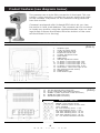
Instruction Manual
12” Wired Security Surveillance Systems
Manuel D'Instruction
Systèmes De Surveillance De Sécurité De câble Par 12"
1202
now you can see
www.svat.com
TABLE OF CONTENTS
ENGLISH
PAGE #
Table Of Contents . . . . . . . . . . . . . . . . . . . . . . . . . . . . . . . . . . . . . . . . . . . . . . . . .
Introduction / Whats Included . . . . . . . . . . . . . . . . . . . . . . . . . . . . . . . . . . . . . . . .
Product Features . . . . . . . . . . . . . . . . . . . . . . . . . . . . . . . . . . . . . . . . . . . . . . . . .
Installation / How To Operate . . . . . . . . . . . . . . . . . . . . . . . . . . . . . . . . . . . . . . . .
Troubleshooting / Specifications . . . . . . . . . . . . . . . . . . . . . . . . . . . . . . . . . . . . . .
Warranty . . . . . . . . . . . . . . . . . . . . . . . . . . . . . . . . . . . . . . . . . . . . . . . . . . . . . . . .
FRANÇAIS
2
3
4
5
6
7
PAGE #
Introduction / Ce qui Est Inclus . . . . . . . . . . . . . . . . . . . . . . . . . . . . . . . . . . . . . . . 8
Caractéristiques du produit . . . . . . . . . . . . . . . . . . . . . . . . . . . . . . . . . . . . . . . . . . 9
Installation/Comment Fonctionner . . . . . . . . . . . . . . . . . . . . . . . . . . . . . . . . . . . . . 10
Dépannage/Caractéristiques . . . . . . . . . . . . . . . . . . . . . . . . . . . . . . . . . . . . . . . . . 11
Garantie . . . . . . . . . . . . . . . . . . . . . . . . . . . . . . . . . . . . . . . . . . . . . . . . . . . . . . . . 12
2
w w w . s v a t . c o m
INTRODUCTION
Congratulations on your purchase of SVAT’s ClearVu 1202. You will soon
find out that this product has many applications, some that we may not
even have mentioned. The following instruction manual will go over your
products, its features, and how to install it. Please read over all of the
instructions and maintenance information so you can extend the life of
this great product.
For more information on your wired security system and on any other
SVAT product, visit www.svat.com.
Please note that SVAT does not endorse any applications of this unit for any illegal activities.
What's included:
The following components should be included with your system. Please
check that you have them all before begining installation:
A: 2x B/W CCD Cameras with 6 Infrared LEDs
B: 12" 4 Channel Monitor
C: Remote Control (batteries not included)
D: 18V DC 2400mA Power Adapter
E: 2x 60' DIN(Audio/Video) Cable
F: 4x BNC to RCA Connectors
Not Shown: Warning Stickers, Warranty Registration, Crime Stoppers insert,
Mounting Harware and Manual
A
B
C
D
E
F
*Actual Product May Not Be Exactly As Shown
3
w w w . s v a t . c o m
Product Features (see diagrams below)
The camera uses a 4 pin DIN connection in the back. This connection, using one plug, contains the power, audio and video
for the camera. The power for the camera is being received
from the monitor.
Camera is equipped with 6 infrared LEDS which let you view
the action in near total darkness. The camera can be mounted
in virually any position using the supplied bracket, even on ceilings (simply unscrew the bracket from the bottom of the camera and screw it in to the top)
MONITOR FRONT VIEW
9
1.
2.
3.
4.
5.
6.
7.
8.
9.
10.
11.
12.
13.
14.
15.
16.
10 11 12 13
16
15
(FIG-1)
Headhone jack
50/60 Hz system switch
V-Hold adjustment knob
Brightness control knob
Contrast adjustment knob
AUTO switch
TIME switch
VOLUME adjustment switch
C1 button + Auto Timer Light 2 sec
C2 button + Auto Timer Light 5 sec
C3 button + Auto Timer Light 10 sec
C4 button + Auto Timer Light 15 sec
TALK button +Auto Timer Light 20 sec
REC (Remote Control Sensor)
POWER button
Power Button Light
14
8
7
12 3
4
5
6
MONITOR BACK VIEW
17.
18.
19.
20.
21.
18V DC 2400mA Power Input Jack
CH1-4 (Video/Audio Input DIN Connector)
VIDEO1-4 (Video Input RCA or BNC Connector)
VIDEO OUT (BNC Connector)
AUDIO OUT (BNC Connector)
REMOTE CONTROL
POWER: Turns monitor on/off
AUTO: switches system to auto mode
TALK: dissabled
2S: Auto Switching Timer - 2 sec
5S: Auto Switching Timer - 5 sec
10S: Auto Switching Timer - 10 sec
15S: Auto Switching Timer - 15 sec
20S: Auto Switching Timer - 20 sec
C1 - C4: Switches between Cameras
20
19
17
18
21
4
w w w . s v a t . c o m
(FIG-2)
Installation
CAUTION: Before connecting the power and switching the monitor ON make sure all cameras are connected properly.
1.
2.
Locate the area you would like to place your camera. Please note
that you have a maximum distance of 60ft supplied with this unit.
You will have to rotate the camera bracket to uncover the screw
insertion areas. Install the camera accordingly.
Note: the camera can operate standing alone but screws will provide
more support. (Picture on right)
3.
Using DIN Connector plug one end of the supplied 60' cable to the back of the
camera and the other end to the back of the monitor.
4.
You can also use the supplied BNC to RCA connector to convert the BNC jack to RCA. This way
you can plug in your camcorder or any other video device to the monitor. This connection is for
VIDEO only, no audio.
CAUTION: Do NOT use CH 1-4 and VIDEO 1-4 INPUTS at the same time. You must only use either
DIN or BNC jacks. Using both inputs at the same time may damage the unit.
5.
This system can also be connected to another monitor, VCR or TV using the the VIDEO and AUDIO
OUT jacks. Simply slip on the BNC connector and using any standard RCA cable (not supplied)
connect it to VIDEO/AUDIO IN on another system.
How To Operate:
1.
After all cameras are connected, pressing the POWER button will turn the system on (LED should
light up). Although the system is turned on the monitor will remain off until you press any of the
four camera buttons (C1 - C4)
2.
After turning the unit on. Pressing C1 - C4 will switch the monitor to the corresponding camera.
3.
Press the AUTO button to have the monitor automatically switch between all cameras. This system
supports up to 4 cameras at one time. If you only have 2 cameras connected the monitor will skip
unused channels and will not display a grey screen.
4.
A green LED light will light up for all unused channel. Example: if you have a camera connected
to C1 and C2, LED above C3 and C4 will be green.
5.
AUTO switching between cameras. Simply press the TIME button and you will notice a
RED light flashing above the C1-4, TALK button. Pressing the TIME button again will let you choose
the time intervals of what the monitor will use to switch between each camera. There are five
pre-set timers: 2, 5, 10, 15 and 20 seconds.
6.
After choosing your desired time sequence press the AUTO button to turn auto switching ON.
7.
You can adjust the volume output for the monitor by sliding the VOLUME knob to the right. If the
cameras are too close to the monitor or any object you may experience high pitch noise.
8.
If your screen appears to be flickering or is too bright/dark try adjusting the corresponding knobs
found inside the flap on the left hand side of the monitor. To open the flap simply press where
marked to do so. (FIG-1)
5
w w w . s v a t . c o m
Troubleshooting
Please read this manual carefully before using this product. If you have any difficulties using this unit,
please consult the following checklist.
No Picture or Sound:
- Make sure the power adapter is properly plugged. The red LED above the POWER button should
be illuminated.
- Double check all the camera wiring is plugged in correctly. Do NOT use CH 1-4 and VIDEO 1-4 INPUTS
at the same time. You must only use either DIN or BNC jacks.
- Press any of the four channel buttons C1-C4 to turn switch to a desired camera.
Blurry Image:
- Rotate the lens on the camera with your fingers to focus it.
Care and maintenance
• Keep all parts and accessories out of reach of young children.
• Do not attempt to open the case. Non-expert handling of the device
may damage it.
• Do not use or store in dusty, dirty or moist areas. This is an indoor unit.
• Do not store in hot areas. High temperatures can shorten the life of
electronic devices and warp or melt certain plastics.
• Do not store in very cold areas. When the system warms up
(to its normal temperature), moisture can form inside the case, which
may damage electronic circuit boards.
• Do not drop, knock, or shake it. Rough handling can break internal
circuit boards.
• Do not use harsh chemicals, cleaning solvents, or strong detergents
when cleaning.
• Operate this product using only the power supply included with it or
provided as an accessory.
SPECIFICATIONS:
Camera (ClearVu 33)
Image Sensor . . . . . . . . . . . . . . . . . . . . . . .
Resolution . . . . . . . . . . . . . . . . . . . . . . . . . .
Lens . . . . . . . . . . . . . . . . . . . . . . . . . . . . . . .
Min Illumination . . . . . . . . . . . . . . . . . . . . . .
Signal Noise . . . . . . . . . . . . . . . . . . . . . . . . .
Audio . . . . . . . . . . . . . . . . . . . . . . . . . . . . . .
Dimentions . . . . . . . . . . . . . . . . . . . . . . . . .
Weight . . . . . . . . . . . . . . . . . . . . . . . . . . . . .
Power Supply . . . . . . . . . . . . . . . . . . . . . . . .
Power Consumption . . . . . . . . . . . . . . . . . .
1/3" CCD B/W lens
380 TV lines
3.6 mm
0 lux with IR up to 10 feet
>48dB
Microphone Built-in
2” x 1.5” x 2.5”
2.5 lbs (approx.)
12V DC from monitor
<2W
Monitor (12” B/W):
Screen Size . . . . . . . . . . . . . . . . . . . . . . . . . .
Resolution . . . . . . . . . . . . . . . . . . . . . . . . . . .
Video Out . . . . . . . . . . . . . . . . . . . . . . . . . .
Audio Out . . . . . . . . . . . . . . . . . . . . . . . . . .
Power Supply Input . . . . . . . . . . . . . . . . . . .
Power Supply Output . . . . . . . . . . . . . . . . .
Power Consumption . . . . . . . . . . . . . . . . . .
Opeting Temperature . . . . . . . . . . . . . . . . .
Dimentions . . . . . . . . . . . . . . . . . . . . . . . . .
Weight . . . . . . . . . . . . . . . . . . . . . . . . . . . . .
12” diagonal
700 lines center
1Vp-p 75 Ohm
1Vp-p 600 Ohm
120V 60Hz 650mA
18V DC 2400mA
<36W
7OF to 143OF (-15OC to 60OC)
11.75” x 11.75” x 11.5”
8 kg (19.5 lbs)approx.
6
w w w . s v a t . c o m
PRODUCT WARRANTY
We take quality very seriously. This is why all of our products
come with a one year warranty from the original purchase date
against defects in workmanship and materials.
If you have warranty or support issues please contact us using any of the following methods:
SVAT Electronics USA
2315 Whirlpool St., Unit 333
NIagara Falls, New York
USA 14305
SVAT Electronics Canada
4080 Montrose Road
Niagara Falls, ON
Canada L2H 1J9
Phone: 866.946.7828
Fax: 888.771.1701
Email: [email protected]
Website: www.svat.com
Warranty Terms
1. SVAT products are guaranteed for a period of one year from the date of purchase gainst defects in
workmanship and materials. This warranty is limited to the repair, replacement or refund of the purchase price
at SVAT's option.
2. When service is required, the warranty is validated by the submission of a fully completed warranty card.
3. This warranty becomes void if the product shows evidence of having been misused, mishandled or tampered
with contrary to the applicable instruction manual.
4. Routine cleaning, normal cosmetic and mechanical wear and tear are not covered under the terms of this
warranty.
5. The warranty expressly provided for herein is the sole warranty provided in connection with the product itself
and no other warranty, expressed or implied is provided. SVAT assumes no responsibilities for any other
claims not specifically mentioned in this warranty.
6. This warranty does not cover the shipping cost, insurance or any other incidental charges.
7. You MUST call SVAT before sending any product back for repair. You will be given a Return Authorization
number. When returning the product for warranty service, please pack it carefully in the original box with all
supplied accessories, and enclose your original receipt or copy, and a brief explanation of the problem
(include RA #).
8. This warranty is valid only in Canada and the U.S.A.
9. This warranty card cannot be re-issued.
CAUTION
RISK OF ELECTRIC SHOCK, DO NOT OPEN
TO REDUCE THE RISK OF ELECTRIC SHOCK, DO NOT REMOVE THE COVER (BACK).
NO USER SERVICABLE PARTS INSIDE. REFER SERVICING TO
QUALIFIED SERVICE PERSONNEL.
Graphic Symbol Explanation:
The lightning flash with arrowhead symbol, within an equilateral triangle, is intended to
alert the user to the presence of uninsulated “dangerous voltage” within the product’s
enclosure that may be of sufficient magnitude to constitute a risk of electric shock to persons.
The exclamation point within an equilateral triangle is intended to alert the user to the
presence of important operating maintenance (servicing) instructions in the literature
accompanying the appliance.
WARNING: TO PREVENT FIRE OR SHOCK HAZARDS, DO NOT EXPOSE THIS UNIT
TO RAIN OR MOISTURE
7
w w w . s v a t . c o m
INTRODUCTION
Félicitations sur votre achat de ClearVu 1202 de SVAT. Vous découvrirez
bientôt que ce produit a beaucoup d'applications, certains que nous
avons pu même ne pas avoir mentionnés. Le manuel d'instruction suivant
ira au-dessus de vos produits, ses dispositifs, et comment l'installer.
L'excédent svp lu tout des instructions et de l'information d'entretien ainsi
de vous peut prolonger la vie de ce grand produit.
Pour plus d'information sur votre système de câble de sécurité et sur tout
autre produit de SVAT, visite www.svat.com
Veuillez noter que SVAT n'approuve aucune application de cette unité pour aucune activité illégale
Ce qui est inclus :
Les composants suivants devraient être inclus avec votre système.
Veuillez vérifier que vous les avez tous avant de begining l'installation :
A: appareils-photo de CCD de 2x B/W avec 6 LED infrarouges
B: 12"Moniteur Des 4 Manche
C: Télécommande (batteries non incluses)
D: 18V Adapteur De Puissance de C.C 2400mA
E: Câble De 2x 60'DIN(Audio/Video)
F: 4x BNC aux connecteurs de RCA
Non montré : Autocollants, enregistrement de garantie, insertion de taquets
de crime, support Harware et manuel d'avertissement
A
B
C
D
E
F
* Le Produit Réel Peut Ne pas être Exactement Comme Montré
8
w w w . s v a t . c o m
Caractéristiques du produit (voir des diagrammes ci-dessous)
L'appareil-photo utilise 4 une goupille raccordement DIN dans
le dos. Ce raccordement, à l'aide d'une prise, contient la puissance, l'acoustique et la vidéo pour l'appareil-photo. La puissance pour l'appareil-photo est reçue du moniteur.
L'appareil-photo est équipé de 6 LED infrarouges qui vous laissent regarder l'action dans l'obscurité totale proche. L'appareilphoto peut être monté dans virually n'importe quelle position à
l'aide de la parenthèse fournie, même sur des plafonds (dévissez simplement la parenthèse du fond de l'appareil-photo et
vissez-la dedans jusqu au dessus)
SURVEILLEZ LA VUE DE FACE
9
1.
2.
3.
4.
5.
6.
7.
8.
9.
10.
11.
12.
13.
14.
15.
16.
10 11 12 13
16
15
(FIG-1)
Cric de Headhone
commutateur de système de 50/60 hertz
V-Tenez le bouton d'ajustement
Bouton de contrôle de luminosité
Bouton d'ajustement de contraste
Commutateur AUTOMATIQUE
Commutateur horaire
Commutateur d'ajustement de VOLUME
Bouton C1 + lumière automatique 2 sec
Bouton C2 + lumière automatique 5 sec
Bouton C3 + lumière automatique 10 sec
Bouton C4 + lumière automatique 15 sec
Lumière 20 sec du bouton +Auto d'ENTRETIEN
REC (Sonde De Télécommande)
Bouton de PUISSANCE
Lumière De Bouton De Puissance
14
8
7
12 3
4
5
6
SURVEILLEZ LA VUE ARRIÈRE
17.
18.
19.
20.
21.
(FIG-2)
18V Puissance fournie de C.C 2400mA Jack
CH1-4 (Connecteur D'Entrée DIN De Video/Audio)
VIDEO1-4 (entrée visuelle RCA ou connecteur de BNC)
VIDÉO DEHORS (Connecteur de BNC)
ACOUSTIQUE DEHORS (Connecteur de BNC)
TÉLÉCOMMANDE
PUISSANCE : Les tours surveillent "Marche/Arrêt"
AUTOMOBILE : commute le système au mode
automatique
ENTRETIEN : handicapé
2S : Temporisateur automatique de commutation
5S : Temporisateur automatique de commutation
10S : Temporisateur automatique de commutation
15S : Temporisateur automatique de commutation
20S : Temporisateur automatique de commutation
C1 - C4 : Commutateurs entre les appareils-photo
20
19
17
18
21
9
w w w . s v a t . c o m
Installation
ATTENTION : Avant de relier la puissance et commuter le moniteur assurez-vous DESSUS que tous les
appareils-photo sont reliés correctement.
1.
2.
Localisez le secteur que vous voudriez placer votre appareil-photo. Veuillez noter que vous
avez une distance maximum de 60ft fournis avec cette unité.
Vous devrez tourner la parenthèse d'appareil-photo pour découvrir les
secteurs d'insertion de vis. Installez l'appareil-photo en conséquence. Note :
l'appareil-photo peut actionner seul debout mais les vis fourniront plus d'ap
pui. (image sur la droite)
3.
En utilisant le connecteur DIN branchez une extrémité du câble 60'fourni au
dos de l'appareil-photo et l'autre extrémité au dos du moniteur.
4.
Vous pouvez également employer le BNC fourni au connecteur de RCA pour convertir le cric de
BNC en RCA. De cette façon vous pouvez brancher votre caméscope ou n'importe quel autre
dispositif visuel au moniteur. Ce raccordement est pour la VIDÉO seulement, aucune acoustique.
ATTENTION : N'utilisez pas ch 1-4 et VIDÉO 1-4 ENTRÉES en même temps. Vous devez seulement
employer des crics DIN ou de BNC. Employer les deux entrées en même temps peut endom
mager l'unité.
5.
Ce système peut également être relié à moniteur, à un magnétoscope ou à une TV différent en
utilisant la la VIDÉO et l'ACOUSTIQUE HORS des crics. Simplement la glissade sur le connecteur de
BNC et employer n'importe quel câble standard de RCA (non fourni) le relient à VIDEO/AUDIO
DEDANS sur un autre système.
Comment Fonctionner :
1.
Après que tous les appareils-photo soient reliés, appuyer sur le bouton de PUISSANCE allumera le
système (la LED devrait s'allumer). Bien que le système soit tourné sur le moniteur reste au loin
jusqu'à ce que vous appuyiez sur n'importe lequel de ces quatre boutons d'appareil-photo (C1 C4)
2.
Après avoir allumé l'unité. Serrant C1 - C4 commutera le moniteur à l'appareil-photo
correspondant.
3.
Appuyez sur le bouton AUTOMATIQUE pour faire commuter le moniteur automatiquement entre
tous les appareils-photo. Ce système soutient jusqu'à 4 appareils-photo en même temps. Si vous
avez seulement 2 appareils-photo ont relié le moniteur sauteront les canaux inutilisés et ne mon
treront pas un gris examinent.
4.
Une lumière verte de LED s'allumera pour tout le canal inutilisé. Exemple : si vous avez un
appareil-photo relié à C1 et à C2, la LED au-dessus de C3 et de C4 sera verte.
5.
Commutation AUTOMATIQUE entre les appareils-photo. Appuyez sur simplement le bouton de
TEMPS et vous noterez une lumière ROUGE clignoter au-dessus du C1-4, bouton d'ENTRETIEN.
Appuyer sur le bouton de TEMPS encore vous laissera choisir les intervalles de temps de ce que le
moniteur emploiera pour commuter entre chaque appareil-photo. Il y a cinq temporisateurs
préréglés : 2. 5, 10, 15 et 20 secondes.
6.
Après le choix de votre ordre désiré de temps appuyez sur le bouton AUTOMATIQUE pour allumer
la commutation automatique.
7.
Vous pouvez ajuster le volume produit au moniteur en glissant le bouton de VOLUME vers la
droite. Si les appareils-photo sont trop près du moniteur ou de n'importe quel objet vous pouvez
éprouver haut lancez le bruit.
8.
Si votre écran semble clignoter ou est trop l'essai de bright/dark ajustant les boutons
correspondants trouvés à l'intérieur de l'aileron du côté de main gauche du moniteur. Pour ouvrir
l'aileron serrez simplement où marqué pour faire ainsi. (FIG-1)
10
w w w . s v a t . c o m
Dépannage
Veuillez lire ce manuel soigneusement avant d'employer ce produit. Si vous avez n'importe quelles difficultés en utilisant cette unité, consultez svp la liste de contrôle suivante.
Aucune image ou bruit :
- assurez-vous que l'adapteur de puissance est correctement branché. La LED rouge au-dessus du
bouton de PUISSANCE devrait être illuminée.
- le double contrôle tout le câblage d'appareil-photo est branché correctement. N'utilisez pas ch 1-4 et
VIDÉO 1-4 ENTRÉES en même temps. Vous devez seulement employer des crics DIN ou de BNC.
- appuyez sur n'importe lequel de ces quatre boutons C1-C4 de canal pour tourner le commutateur à
un appareil-photo désiré.
Image De Blurry :
- tournez l'objectif sur l'appareil-photo avec vos doigts pour le focaliser.
Soin et entretien
• Maintenez tous les pièces et accessoires hors de portée des enfants en bas âge.
• N'essayez pas d'ouvrir la valise. la manipulation d'Non-expert du dispositif peut l'endommager.
• N'employez pas ou pas entreposé dans des secteurs poussiéreux, sales ou moites. C'est une unité
d'intérieur.
• Pas entreposé dans des secteurs chauds. Les températures élevées peuvent raccourcir la vie des
dispositifs électroniques et déformer ou fondre certains plastiques.
• Pas entreposé dans des secteurs très froids. Quand le système réchauffe (à sa température normale),
l'humidité peut former à l'intérieur du cas, qui peut endommager les cartes électroniques.
• Ne le laissez pas tomber, ne frappez pas, ou ne secouez pas. Une manipulation peu soigneuse peut
casser les cartes internes.
• N'employez pas les produits chimiques durs, les dissolvants de nettoyage, ou les détergents forts en
nettoyant.
• Actionnez ce produit en utilisant seulement l'alimentation d'énergie incluse avec elle ou si comme
accessoire.
CARACTÉRISTIQUES:
Appareil-photo (ClearVu 33)
Sonde D'Image . . . . . . . . . . . . . . . . . . . . . .
Résolution . . . . . . . . . . . . . . . . . . . . . . . . . .
Objectif . . . . . . . . . . . . . . . . . . . . . . . . . . . .
Illumination Minimum . . . . . . . . . . . . . . . . . .
Bruit De Signal . . . . . . . . . . . . . . . . . . . . . . .
Audio . . . . . . . . . . . . . . . . . . . . . . . . . . . . . .
Dimentions . . . . . . . . . . . . . . . . . . . . . . . . .
Poids . . . . . . . . . . . . . . . . . . . . . . . . . . . . . . .
Alimentation D'Énergie . . . . . . . . . . . . . . . .
Puissance D'Énergie . . . . . . . . . . . . . . . . . . .
1/3" CCD N/B objectif
380 TV lignes
3.6 mm
0 lux avec IR jusqu'à 10 ft
>48dB
microphone incorporé
2” x 1.5” x 2.5”
2.5 lbs (approx.)
12V DC pour moniteur.
<2W
Moniteur (12” B/W):
Taille D'Écran . . . . . . . . . . . . . . . . . . . . . . . .
Résolution . . . . . . . . . . . . . . . . . . . . . . . . . . .
Vidéo Dehors . . . . . . . . . . . . . . . . . . . . . . .
Acoustique Dehors . . . . . . . . . . . . . . . . . . .
Entrée D'Alimentation D'Énergie . . . . . . . . .
Rendement D'Alimentation D'Énergie . . . .
Puissance D'Énergie . . . . . . . . . . . . . . . . . . .
La Température D'Opeting . . . . . . . . . . . . .
Dimentions . . . . . . . . . . . . . . . . . . . . . . . . .
Poids . . . . . . . . . . . . . . . . . . . . . . . . . . . . . . .
12” diagonal
700 lines center
1Vp-p 75 Ohm
1Vp-p 600 Ohm
120V 60Hz 650mA
18V DC 2400mA
<36W
7OF to 143OF (-15OC to 60OC)
11.75” x 11.75” x 11.5”
8 kg (19.5 lbs)approx.
11
w w w . s v a t . c o m
GARANTIE DE PRODUIT
Nous prenons la qualité très sérieusement. C'est pourquoi tous
nos produits viennent avec une garantie d'un an de la date originale d'achat contre des défauts en exécution et matériaux.
Si vous avez les issues de garantie ou de soutien satisfont nous contactent employant n'importe laquelle
des méthodes suivantes :
SVAT Electronics USA
2315 Whirlpool St., Unit 333
NIagara Falls, New York
USA 14305
SVAT Electronics Canada
4080 Montrose Road
Niagara Falls, ON
Canada L2H 1J9
Phone: 866.946.7828
Fax: 888.771.1701
Email: [email protected]
Website: www.svat.com
Limites De Garantie
1. Les produits de SVAT sont garantis pour une période d'une année de la date d'achat contre défectuosités
l'exécution et défectuosité des matériels. Cette garantie est limitée à la réparation, le remplacement ou le
remboursement du prix d'achat à l'option de SVAT.
2. Quand le service est exigé, la garantie est validée par la soumission d'une carte de garantie entièrement
complétée.
3. Cette garantie devient vide si le produit montre l'évidence d'ayant été employé improprement, malmené ou a
altéré contraire au manuel d'instruction applicable.
4. Le nettoyage de routine, l'usure normale normal, cosmétique et mécanique n'est pas couverte sous les ter
mes de cette garantie.
5. La garantie a pourvu expressément à en ceci est la garantie seule fournie à propos du produit lui-même e
aucune autre garantie, exprimée ou suggérée est fournie. SVAT ne suppose pas de responsabilités pour les
autres réclamations pas en particulier mention né dans cette garantie.
6. Cette garantie ne couvre pas le coût expédiant, l'assurance ou les autres charges accessoires.
7. En retournant le produit pour le service de garantie, s'il vous plaît l'emballer soigneusement dans la boîte
originale avec tous accessoires fournis, et enclore votre carte de garantie, le reçu original ou la copie, et une
explication brève du problème.
8. Cette garantie est valide seulement dans le Canada et les ETATS-UNIS.
9. Cette carte de garantie ne peut pas être la réédition.
ATTENTION
LE RISQUE DE DÉCHARGE ÉLECTRIQUE, NE S'OUVRENT PAS
POUR RÉDUIRE LE RISQUE DE DÉCHARGE ÉLECTRIQUE, N'ENLEVEZ PAS LA COUVERTURE (ARRIÈRE). AUCUNES PIÈCES DE L'UTILISATEUR SERVICABLE À L'INTÉRIEUR.
RÉFÉREZ-VOUS L'ENTRETIEN AU PERSONNEL DE SERVICE QUALIFIÉ.
Explication Graphique De Symbole :
Le flash de foudre avec le symbole de pointe de flèche, dans une triangle equilateral, est
prévu pour alerter l'utilisateur à la présence "de la tension dangereuse" non isolée dans la
clôture du produit qui peut être de la grandeur suffisante pour constituer un risque de
décharge électrique aux personnes.
Le point d'exclamation dans une triangle equilateral est prévu pour alerter l'utilisateur à la
présence des instructions de fonctionnement importantes d'entretien (entretien) dans la
littérature accompagnant l'appareil.
AVERTISSEMENT : POUR EMPÊCHER DES RISQUES DU FEU OU DE CHOC, N'EXPOSEZ PAS CETTE UNITÉ À LA PLUIE OU À L'HUMIDITÉ
12
w w w . s v a t . c o m
www.svat.com
Disclaimer: SVAT does not endorse of any of SVAT products for any illegal activites.
SVAT is not responsible or liable in any way shape or form for any damage, vandalism,
theft or any other action that may occur while a SVAT product is in use by the purchaser.
Déni : SVAT n'approuve d'aucun de produits de SVAT pour aucun activites illégal. SVAT n'est pas
responsable ou responsable de quelque façon forme ou forme d'aucun dommage, de
vandalisme, de vol ou d'aucune autre action qui peuvent se produire tandis qu'un produit
de SVAT est en service par l'acheteur.