1
Netra™ 440 Server System
Administration Guide
Sun Microsystems, Inc.
www.sun.com
Part No. 817-3884-11
August 2004, Revision A
Submit comments about this document at: http://www.sun.com/hwdocs/feedback
Copyright 2004 Sun Microsystems, Inc., 4150 Network Circle, Santa Clara, California 95054, U.S.A. All rights reserved.
Sun Microsystems, Inc. has intellectual property rights relating to technology that is described in this document. In particular, and without
limitation, these intellectual property rights may include one or more of the U.S. patents listed at http://www.sun.com/patents and one or
more additional patents or pending patent applications in the U.S. and in other countries.
This document and the product to which it pertains are distributed under licenses restricting their use, copying, distribution, and
decompilation. No part of the product or of this document may be reproduced in any form by any means without prior written authorization of
Sun and its licensors, if any.
Third-party software, including font technology, is copyrighted and licensed from Sun suppliers.
Parts of the product may be derived from Berkeley BSD systems, licensed from the University of California. UNIX is a registered trademark in
the U.S. and in other countries, exclusively licensed through X/Open Company, Ltd.
Sun, Sun Microsystems, the Sun logo, AnswerBook2, docs.sun.com, VIS, Sun StorEdge, Solstice DiskSuite, Java, SunVTS, Netra, and Solaris are
trademarks or registered trademarks of Sun Microsystems, Inc. in the U.S. and in other countries.
All SPARC trademarks are used under license and are trademarks or registered trademarks of SPARC International, Inc. in the U.S. and in other
countries. Products bearing SPARC trademarks are based upon an architecture developed by Sun Microsystems, Inc.
The OPEN LOOK and Sun™ Graphical User Interface was developed by Sun Microsystems, Inc. for its users and licensees. Sun acknowledges
the pioneering efforts of Xerox in researching and developing the concept of visual or graphical user interfaces for the computer industry. Sun
holds a non-exclusive license from Xerox to the Xerox Graphical User Interface, which license also covers Sun’s licensees who implement OPEN
LOOK GUIs and otherwise comply with Sun’s written license agreements.
U.S. Government Rights—Commercial use. Government users are subject to the Sun Microsystems, Inc. standard license agreement and
applicable provisions of the FAR and its supplements.
DOCUMENTATION IS PROVIDED "AS IS" AND ALL EXPRESS OR IMPLIED CONDITIONS, REPRESENTATIONS AND WARRANTIES,
INCLUDING ANY IMPLIED WARRANTY OF MERCHANTABILITY, FITNESS FOR A PARTICULAR PURPOSE OR NON-INFRINGEMENT,
ARE DISCLAIMED, EXCEPT TO THE EXTENT THAT SUCH DISCLAIMERS ARE HELD TO BE LEGALLY INVALID.
Copyright 2004 Sun Microsystems, Inc., 4150 Network Circle, Santa Clara, Californie 95054, Etats-Unis. Tous droits réservés.
Sun Microsystems, Inc. a les droits de propriété intellectuels relatants à la technologie qui est décrit dans ce document. En particulier, et sans la
limitation, ces droits de propriété intellectuels peuvent inclure un ou plus des brevets américains énumérés à http://www.sun.com/patents et
un ou les brevets plus supplémentaires ou les applications de brevet en attente dans les Etats-Unis et dans les autres pays.
Ce produit ou document est protégé par un copyright et distribué avec des licences qui en restreignent l’utilisation, la copie, la distribution, et la
décompilation. Aucune partie de ce produit ou document ne peut être reproduite sous aucune forme, par quelque moyen que ce soit, sans
l’autorisation préalable et écrite de Sun et de ses bailleurs de licence, s’il y ena.
Le logiciel détenu par des tiers, et qui comprend la technologie relative aux polices de caractères, est protégé par un copyright et licencié par des
fournisseurs de Sun.
Des parties de ce produit pourront être dérivées des systèmes Berkeley BSD licenciés par l’Université de Californie. UNIX est une marque
déposée aux Etats-Unis et dans d’autres pays et licenciée exclusivement par X/Open Company, Ltd.
Sun, Sun Microsystems, le logo Sun, AnswerBook2, docs.sun.com, VIS, Sun StorEdge, Solstice DiskSuite, Java, SunVTS, Netra, et Solaris sont
des marques de fabrique ou des marques déposées de Sun Microsystems, Inc. aux Etats-Unis et dans d’autres pays.
Toutes les marques SPARC sont utilisées sous licence et sont des marques de fabrique ou des marques déposées de SPARC International, Inc.
aux Etats-Unis et dans d’autres pays. Les produits portant les marques SPARC sont basés sur une architecture développée par Sun
Microsystems, Inc.
L’interface d’utilisation graphique OPEN LOOK et Sun™ a été développée par Sun Microsystems, Inc. pour ses utilisateurs et licenciés. Sun
reconnaît les efforts de pionniers de Xerox pour la recherche et le développement du concept des interfaces d’utilisation visuelle ou graphique
pour l’industrie de l’informatique. Sun détient une license non exclusive de Xerox sur l’interface d’utilisation graphique Xerox, cette licence
couvrant également les licenciées de Sun qui mettent en place l’interface d ’utilisation graphique OPEN LOOK et qui en outre se conforment
aux licences écrites de Sun.
LA DOCUMENTATION EST FOURNIE "EN L’ÉTAT" ET TOUTES AUTRES CONDITIONS, DECLARATIONS ET GARANTIES EXPRESSES
OU TACITES SONT FORMELLEMENT EXCLUES, DANS LA MESURE AUTORISEE PAR LA LOI APPLICABLE, Y COMPRIS NOTAMMENT
TOUTE GARANTIE IMPLICITE RELATIVE A LA QUALITE MARCHANDE, A L’APTITUDE A UNE UTILISATION PARTICULIERE OU A
L’ABSENCE DE CONTREFAÇON.
Contents
Contents
1.
i
Figures
v
Tables
vii
Preface
ix
Configuring the System Console
1
Communicating With the System
1
What the System Console Does
Using the System Console
About the sc> Prompt
3
3
8
Access Through Multiple Controller Sessions
Reaching the sc> Prompt
OpenBoot ok Prompt
9
9
9
Reaching the ok Prompt
For More Information
10
13
Getting to the ok Prompt
13
Switching Between the ALOM System Controller and the System Console
Accessing the System Controller
15
16
i
Using the Serial Management Port
16
Activating the Network Management Port
17
Accessing the System Console Through a Terminal Server
19
Accessing the System Console Through a TIP Connection
22
Modifying the /etc/remote File
25
Accessing the System Console Through an Alphanumeric Terminal
Verifying Serial Port Settings on TTYB
28
Accessing the System Console Through a Local Graphics Monitor
System Console OpenBoot Configuration Variable Settings
2.
Managing RAS Features and System Firmware
ALOM System Controller
26
29
31
33
34
Logging In To the ALOM System Controller
About the scadm Utility
34
35
Controlling the Locator LED
OpenBoot Emergency Procedures
37
39
OpenBoot Emergency Procedures for Systems With Non-USB Keyboards
OpenBoot Emergency Procedures for Systems With USB Keyboards
Automatic System Recovery
Auto-Boot Options
42
Error Handling Summary
Reset Scenarios
41
43
44
Automatic System Recovery User Commands
44
Enabling and Disabling Automatic System Recovery
Obtaining Automatic System Recovery Information
Unconfiguring and Reconfiguring Devices
44
46
46
Enabling the Hardware Watchdog Mechanism and Its Options
Multipathing Software
50
For More Information
ii
50
Netra 440 Server System Administration Guide • August 2004
49
40
39
3.
Managing Disk Volumes
Disk Volumes
51
51
Volume Management Software
52
VERITAS Dynamic Multipathing
Sun StorEdge Traffic Manager
For More Information
RAID Technology
52
53
54
Disk Concatenation
54
RAID 0: Disk Striping
RAID 1: Disk Mirroring
55
55
RAID 5: Disk Striping With Parity
Hot-Spares
52
56
56
Hardware Disk Mirroring
56
Physical Disk Slot Numbers, Physical Device Names, and Logical Device
Names 57
A.
OpenBoot Configuration Variables
B.
Alarm Relay Output Application Programming Interface
Index
67
71
77
Contents
iii
iv
Netra 440 Server System Administration Guide • August 2004
Figures
FIGURE 1-1
Directing the System Console to Different Ports and Different Devices 4
FIGURE 1-2
Serial Management Port on the ALOM System Controller Card–Default Console
Connection 5
FIGURE 1-3
Alternative Console Ports (Require Additional Configuration)
FIGURE 1-4
Separate System Console and System Controller “Channels”
FIGURE 1-5
Patch Panel Connection Between a Terminal Server and a Netra 440 Server
FIGURE 1-6
TIP Connection Between a Netra 440 Server and Another Sun System
FIGURE 3-1
Graphical Representation of Disk Concatenation 54
FIGURE 3-2
Graphical Representation of Disk Striping 55
FIGURE 3-3
Graphical Representation of Disk Mirroring
6
15
20
22
55
v
vi
Netra 440 Server System Administration Guide • August 2004
Tables
TABLE 1-1
Ways of Communicating With the System
2
TABLE 1-2
Ways of Accessing the ok Prompt
TABLE 1-3
Pin Crossovers for Connecting to a Typical Terminal Server
TABLE 1-4
OpenBoot Configuration Variables That Affect the System Console
TABLE 2-1
Stop Key Command Functions for Systems With Standard (Non-USB) Keyboards 39
TABLE 2-2
Device Identifiers and Devices 47
TABLE 3-1
Disk Slot Numbers, Logical Device Names, and Physical Device Names 57
TABLE A-1
OpenBoot Configuration Variables Stored on the System Configuration Card 67
14
20
31
vii
viii
Netra 440 Server System Administration Guide • August 2004
Preface
The Netra 440 Server System Administration Guide is written for experienced system
administrators. It includes general descriptive information about the NetraTM 440
server and detailed instructions for configuring and administering the server. To use
the information in this manual, you must have working knowledge of computer
network concepts and terms, and advanced familiarity with the Solaris™ Operating
System (Solaris OS).
How This Book Is Organized
The Netra 440 Server System Administration Guide is divided into the following
chapters:
■
Chapter 1 describes the system console and how to access it.
■
Chapter 2 describes the tools used to configure system firmware, including SunTM
Advanced Lights Out Manager (ALOM) system controller environmental
monitoring, automatic system recovery (ASR), hardware watchdog mechanism,
and multipathing software. In addition, it describes how to unconfigure and
reconfigure a device manually.
■
Chapter 3 describes how to manage internal disk volumes and devices.
This manual also includes the following reference appendixes:
■
Appendix A provides a list of all OpenBoot configuration variables, and a short
description of each.
■
Appendix B provides a sample program that illustrates how to get/set the
status of the alarms.
ix
Using UNIX Commands
This document might not contain information on basic UNIX® commands and
procedures such as shutting down the system, booting the system, and configuring
devices. See the following for this information:
■
Software documentation that you received with your system
■
Solaris OS documentation, which is at
http://docs.sun.com
Shell Prompts
x
Shell
Prompt
C shell
machine-name%
C shell superuser
machine-name#
Bourne shell and Korn shell
$
Bourne shell and Korn shell superuser
#
Netra 440 Server System Administration Guide • August 2004
Typographic Conventions
Typeface*
Meaning
Examples
AaBbCc123
The names of commands, files,
and directories; on-screen
computer output
Edit your.login file.
Use ls -a to list all files.
% You have mail.
AaBbCc123
What you type, when contrasted
with on-screen computer output
% su
Password:
AaBbCc123
Book titles, new words or terms,
words to be emphasized.
Replace command-line variables
with real names or values.
Read Chapter 6 in the User’s Guide.
These are called class options.
You must be superuser to do this.
To delete a file, type rm filename.
* The settings on your browser might differ from these settings.
Related Documentation
Application
Title
Part Number
Late-breaking product
information
Netra 440 Server Release Notes
817-3885-xx
Product description
Netra 440 Server Product Overview
817-3881-xx
Installation instructions
Netra 440 Server Installation Guide
817-3882-xx
Administration
Netra 440 Server System Administration
Guide
817-3884-xx
Parts installation and
removal
Netra 440 Server Service Manual
817-3883-xx
Diagnostics and
troubleshooting
Netra 440 Server Diagnostics and
Troubleshooting Guide
817-3886-xx
Advanced Lights Out
Manager (ALOM) system
controller
Advanced Lights Out Manager User’s
Guide
817-5481-xx
Preface
xi
Accessing Sun Documentation
You can view, print, or purchase a broad selection of Sun documentation, including
localized versions, at:
http://www.sun.com/documentation
Third-Party Web Sites
Sun is not responsible for the availability of third-party web sites mentioned in this
document. Sun does not endorse and is not responsible or liable for any content,
advertising, products, or other materials that are available on or through such sites
or resources. Sun will not be responsible or liable for any actual or alleged damage
or loss caused by or in connection with the use of or reliance on any such content,
goods, or services that are available on or through such sites or resources.
Contacting Sun Technical Support
If you have technical questions about this product that are not answered in this
document, go to:
http://www.sun.com/service/contacting
Sun Welcomes Your Comments
Sun is interested in improving its documentation and welcomes your comments and
suggestions. You can submit your comments by going to:
http://www.sun.com/hwdocs/feedback
Please include the title and part number of your document with your feedback:
Netra 440 Server System Administration Guide, part number 817-3884-11
xii
Netra 440 Server System Administration Guide • August 2004
CHAPTER
1
Configuring the System Console
This chapter explains what the system console is, describes the different ways of
configuring it on a Netra 440 server, and helps you understand its relation to the
system controller.
Tasks covered in this chapter include:
■
■
■
■
■
■
■
■
■
“Getting to the ok Prompt” on page 13
“Accessing the System Controller” on page 16
“Activating the Network Management Port” on page 17
“Accessing the System Console Through a Terminal Server” on page 19
“Accessing the System Console Through a TIP Connection” on page 22
“Modifying the /etc/remote File” on page 25
“Accessing the System Console Through an Alphanumeric Terminal” on page 26
“Verifying Serial Port Settings on TTYB” on page 28
“Accessing the System Console Through a Local Graphics Monitor” on page 29
Other information in this chapter includes:
■
■
■
■
■
“Communicating With the System” on page 1
“About the sc> Prompt” on page 8
“OpenBoot ok Prompt” on page 9
“Switching Between the ALOM System Controller and the System Console” on
page 15
“System Console OpenBoot Configuration Variable Settings” on page 31
Communicating With the System
To install your system software or to diagnose problems, you need some way to
interact at a low level with the system. The system console is Sun’s facility for doing
this. You use the system console to view messages and issue commands. There can
be only one system console per computer.
1
The serial management port (SERIAL MGT) is the default port for accessing the
system console upon initial system installation. After installation, you can configure
the system console to accept input from and send output to different devices.
TABLE 1-1 lists these devices and where they are discussed in the document.
TABLE 1-1
Ways of Communicating With the System
During
Installation*
After
Installation
• “Accessing the System Controller” on page 16
✓
✓
• “Accessing the System Console Through a Terminal Server”
on page 19
✓
✓
Devices Available for Accessing the System Console
A terminal server attached to the serial management port
(SERIAL MGT) or ttyb. See the following:
✓
• “Verifying Serial Port Settings on TTYB” on page 28
✓
✓
• “Accessing the System Controller” on page 16
✓
✓
• “Accessing the System Console Through an Alphanumeric
Terminal” on page 26
✓
✓
• “System Console OpenBoot Configuration Variable Settings”
on page 31
An alphanumeric terminal or similar device attached to the
serial management port (SERIAL MGT) or ttyb. See the
following:
✓
• “Verifying Serial Port Settings on TTYB” on page 28
✓
✓
• “Accessing the System Controller” on page 16
✓
✓
• “Accessing the System Console Through a TIP Connection”
on page 22
✓
✓
• “System Console OpenBoot Configuration Variable Settings”
on page 31
A TIP line attached to the serial management port (SERIAL
MGT) or ttyb. See the following:
• “Modifying the /etc/remote File” on page 25
✓
• “Verifying Serial Port Settings on TTYB” on page 28
✓
• “System Console OpenBoot Configuration Variable Settings”
on page 31
✓
✓
An Ethernet line connected to the network management port
(NET MGT). See the following:
• “Activating the Network Management Port” on page 17
2
Netra 440 Server System Administration Guide • August 2004
✓
TABLE 1-1
Ways of Communicating With the System (Continued)
During
Installation*
Devices Available for Accessing the System Console
After
Installation
A local graphics monitor (frame buffer card, graphics monitor,
mouse, and so forth). See the following:
• “Accessing the System Console Through a Local Graphics
Monitor” on page 29
✓
• “System Console OpenBoot Configuration Variable Settings”
on page 31
✓
* After initial system installation, you can redirect the system console to take its input from and send its output
to the serial port TTYB.
What the System Console Does
The system console displays status and error messages generated by firmware-based
tests during system startup. After those tests have been run, you can enter special
commands that affect the firmware and alter system behavior. For more information
about tests that run during the boot process, refer to the Netra 440 Server Diagnostics
and Troubleshooting Guide.
Once the operating system is booted, the system console displays UNIX system
messages and accepts UNIX commands.
Using the System Console
To use the system console, you need some means of getting data in to and out of the
system, which means attaching some kind of hardware to the system. Initially, you
might have to configure that hardware, and load and configure appropriate software
as well.
Chapter 1
Configuring the System Console
3
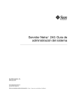
You must also ensure that the system console is directed to the appropriate port on
the Netra 440 server’s back panel—generally, the one to which your hardware
console device is attached (see FIGURE 1-1). You do this by setting the input-device
and output-device OpenBoot configuration variables.
Netra 440 Server
Ports
Console Devices
SERIAL MGT
TIP
Line
OpenBoot Configuration Variable Settings
input-device=ttya
output-device=ttya
NET MGT
System
Console
input-device=ttyb
output-device=ttyb
Terminal
server
ttyb
input-device=keyboard
output-device=screen
FIGURE 1-1
Alphanumeric
terminal
Graphics Card
Graphics
monitor
Directing the System Console to Different Ports and Different Devices
Default System Console Connection Through the Serial
Management and Network Management Ports
On Netra 440 servers, the system console comes preconfigured to allow input and
output only by means of hardware devices connected to the serial or network
management ports. However, because the network management port is not available
until you assign it an IP address, your first connection must be to the serial
management port (SERIAL MGT).
4
Netra 440 Server System Administration Guide • August 2004
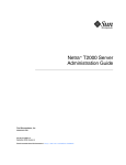
Typically, you connect one of the following hardware devices to the serial
management port:
■
■
■
Terminal server
Alphanumeric terminal or similar device
TIP line connected to another Sun computer
This provides for secure access at the installation site.
ALOM serial management port
ALOM network management port
FIGURE 1-2
Serial Management Port on the ALOM System Controller Card–Default
Console Connection
Using a TIP line might be preferable to connecting an alphanumeric terminal, since
TIP lets you use windowing and operating system features on the machine being
used to make the connection to the Netra 440 server.
Although the Solaris OS sees the serial management port as ttya, the serial
management port is not a general-purpose serial port. If you want to use a generalpurpose serial port with your server—to connect a serial printer, for instance—use
the regular 9-pin serial port on the back panel of the Netra 440. The Solaris OS sees
this port as ttyb.
■
For instructions on accessing the system console through a terminal server, see
“Accessing the System Console Through a Terminal Server” on page 19.
■
For instructions on accessing the system console through an alphanumeric
terminal, see “Accessing the System Console Through an Alphanumeric
Terminal” on page 26.
■
For instructions on accessing the system console through a TIP line, see
“Accessing the System Console Through a TIP Connection” on page 22.
Chapter 1
Configuring the System Console
5
Once you have assigned an IP address to the network management port (NET
MGT), you can connect an Ethernet-capable device to the system console through
your network. This provides for remote monitoring and control. In addition, up to
four simultaneous connections to the system controller sc> prompt are available
through the network management port. For more information, see “Activating the
Network Management Port” on page 17.
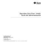
Alternative System Console Configuration
In the default configuration, system controller alerts and system console output
appear interspersed in the same window. After initial system installation, you can
redirect the system console to take its input from and send its output to the serial
port ttyb, or to a graphics card’s port.
Serial port (TTYB)
FIGURE 1-3
USB ports
(for keyboard and mouse)
Six PCI
card slots
Alternative Console Ports (Require Additional Configuration)
The chief advantage of redirecting the system console to another port is that it
allows you to divide system controller alerts and system console output into two
separate windows.
However, there are some serious disadvantages to alternative console configuration:
■
6
Power-on self-text (POST) output can only be directed to the serial management
and network management ports. It cannot be directed to ttyb or to a graphics
card’s port.
Netra 440 Server System Administration Guide • August 2004
■
If you have directed the system console to ttyb, you cannot use this port for any
other serial device.
■
In a default configuration, the serial management and network management ports
allow you to open up to four additional windows through which you can view,
but not affect, system console activity. You cannot open these windows if the
system console is redirected to ttyb or to a graphics card’s port.
■
In a default configuration, the serial management and network management ports
allow you to switch between viewing system console and system controller
output on the same device by typing a simple escape sequence or command. The
escape sequence and command do not work if the system console is redirected to
ttyb or to a graphics card’s port.
■
The system controller keeps a log of console messages, but some messages are not
logged if the system console is redirected to ttyb or to a graphic card’s port. The
omitted information could be important if you need to contact Sun customer
service with a problem.
For all the preceding reasons, the best practice is to leave the system console in its
default configuration.
You change the system console configuration by setting OpenBoot configuration
variables. See “System Console OpenBoot Configuration Variable Settings” on
page 31.
You can also set OpenBoot configuration variables using the ALOM system
controller. For details, refer to the Advanced Lights Out Manager User’s Guide (8175481-xx).
Accessing the System Console Through a Graphics Monitor
The Netra 440 server is shipped without a mouse, keyboard, monitor, or frame
buffer for the display of bitmapped graphics. To install a graphics monitor on the
server, you must install a frame buffer card into a PCI slot, and attach a monitor,
mouse, and keyboard to the appropriate back panel ports.
After starting the system, you might need to install the correct software driver for
the PCI card you have installed. For detailed hardware instructions, see “Accessing
the System Console Through a Local Graphics Monitor” on page 29.
Note – POST diagnostics cannot display status and error messages to a local
graphics monitor.
Chapter 1
Configuring the System Console
7
About the sc> Prompt
The ALOM system controller runs independently of the Netra 440 server and
regardless of system power state. When you connect a Netra 440 server to AC
power, the ALOM system controller immediately starts up, and begins monitoring
the system.
Note – To view ALOM system controller boot messages, you must connect an
alphanumeric terminal to the serial management port before connecting the AC
power cords to the Netra 440 server.
You can log in to the ALOM system controller at any time, regardless of system
power state, as long as AC power is connected to the system and you have a way of
interacting with the system. You can also access the ALOM system controller prompt
(sc>) from the OpenBoot ok prompt or from the Solaris # or % prompt, provided the
system console is configured to be accessible through the serial management and
network management ports. For more information, see the following:
■
“Getting to the ok Prompt” on page 13
■
“Switching Between the ALOM System Controller and the System Console” on
page 15
The sc> prompt indicates that you are interacting with the ALOM system controller
directly. It is the first prompt you see when you log in to the system through the
serial management port or network management port, regardless of system power
state.
Note – When you access the ALOM system controller for the first time, it forces you
to create a user name and password for subsequent access. After this initial
configuration, you will be prompted to enter a user name and password every time
you access the ALOM system controller.
8
Netra 440 Server System Administration Guide • August 2004
Access Through Multiple Controller Sessions
Up to five ALOM system controller sessions can be active concurrently, one session
through the serial management port and up to four sessions through the network
management port. Users of each of these sessions can issue commands at the sc>
prompt. However, only one user at a time can access the system console, and then
only if the system console is configured to be accessible through the serial and
network management ports. For more information, see:
■
■
“Accessing the System Controller” on page 16
“Activating the Network Management Port” on page 17
Any additional ALOM system controller sessions afford passive views of system
console activity, until the active user of the system console logs out. However, the
console -f command, if you enable it, allows users to seize access to the system
console from one another. For more information, see the Advanced Lights Out
Manager User’s Guide (817-5481-xx).
Reaching the sc> Prompt
There are several ways to get to the sc> prompt:
■
If the system console is directed to the serial management and network
management ports, you can type the ALOM system controller escape sequence
(#.).
■
You can log in directly to the ALOM system controller from a device connected to
the serial management port. See “Accessing the System Controller” on page 16.
■
You can log in directly to the ALOM system controller using a connection through
the network management port. See “Activating the Network Management Port”
on page 17.
OpenBoot ok Prompt
A Netra 440 server with the Solaris OS installed is capable of operating at different
run levels. A synopsis of run levels follows. For a full description, refer to the Solaris
system administration documentation.
Most of the time, you operate a Netra 440 server at run level 2 or run level 3, which
are multiuser states with access to full system and network resources. Occasionally,
you might operate the system at run level 1, which is a single-user administrative
state. However, the lowest operational state is run level 0. At this state, it is safe to
turn off power to the system.
Chapter 1
Configuring the System Console
9
When a Netra 440 server is at run level 0, the ok prompt appears. This prompt
indicates that the OpenBoot firmware is in control of the system.
There are a number of scenarios under which OpenBoot firmware control can occur.
■
By default, the system comes up under OpenBoot firmware control before the
operating system is installed.
■
The system boots to the ok prompt when the auto-boot? OpenBoot
configuration variable is set to false.
■
The system transitions to run level 0 in an orderly way when the operating
system is halted.
■
The system reverts to OpenBoot firmware control when the operating system
crashes.
■
During the boot process, when there is a serious hardware problem that prevents
the operating system from running, the system reverts to OpenBoot firmware
control.
■
When a serious hardware problem develops while the system is running, the
operating system transitions smoothly to run level 0.
■
You deliberately place the system under firmware control in order to execute
firmware-based commands or to run diagnostic tests.
It is the last of these scenarios which most often concerns you as an administrator,
since there will be times when you need to reach the ok prompt. Several ways to do
this are outlined in “Reaching the ok Prompt” on page 10. For detailed instructions,
see “Getting to the ok Prompt” on page 13.
Reaching the ok Prompt
There are several ways to reach the ok prompt, depending on the state of the system
and the means by which you are accessing the system console. In order of
desirability, these are:
■
■
■
■
■
Graceful shutdown
ALOM system controller break or console command
L1-A (Stop-A) keys or Break key
Externally initiated reset (XIR)
Manual system reset
A discussion of each method follows. For step-by-step instructions, see “Getting to
the ok Prompt” on page 13.
10
Netra 440 Server System Administration Guide • August 2004
Graceful Shutdown
The preferred method of reaching the ok prompt is to shut down the operating
system by issuing an appropriate command (for example, the shutdown, init, or
uadmin command) as described in Solaris system administration documentation.
You can also use the system Power button to initiate a graceful system shutdown.
Gracefully shutting down the system prevents data loss, enables you to warn users
beforehand, and causes minimal disruption. You can usually perform a graceful
shutdown, provided the Solaris OS is running and the hardware has not experienced
serious failure.
You can also perform a graceful system shutdown from the ALOM system controller
command prompt.
ALOM System Controller break or console Command
Typing break from the sc> prompt forces a running Netra 440 server to drop into
OpenBoot firmware control. If the operating system is already halted, you can use
the console command instead of break to reach the ok prompt.
After forcing the system into OpenBoot firmware control, be aware that issuing
certain OpenBoot commands (like probe-scsi, probe-scsi-all, or probe-ide)
might hang the system.
L1-A (Stop-A) Keys or Break Key
When it is impossible or impractical to shut down the system gracefully, you can get
to the ok prompt by typing the L1-A (Stop-A) key sequence from a Sun keyboard. If
you have an alphanumeric terminal attached to the Netra 440 server, press the Break
key.
After forcing the system into OpenBoot firmware control, be aware that issuing
certain OpenBoot commands (like probe-scsi, probe-scsi-all, or probe-ide)
might hang the system.
Note – These methods of reaching the ok prompt will only work if the system
console has been redirected to the appropriate port. For details, see “System Console
OpenBoot Configuration Variable Settings” on page 31.
Chapter 1
Configuring the System Console
11
Externally Initiated Reset (XIR)
Use the ALOM system controller reset -x command to execute an externally
initiated reset (XIR). Forcing an XIR might be effective in breaking the deadlock that
is hanging up the system. However, an XIR also precludes the orderly shutdown of
applications, and so it is not the preferred method of reaching the ok prompt, unless
you are troubleshooting these types of system hangs. Generating an XIR has the
advantage of allowing you to issue the sync command to produce a dump file of the
current system state for diagnostic purposes.
For more information, refer to:
■
■
Netra 440 Server Diagnostics and Troubleshooting Guide (817-3886-xx)
Advanced Lights Out Manager User’s Guide (817-5481-xx)
Caution – Because an XIR precludes an orderly shutdown of applications, it should
only be attempted if previously described methods do not work.
Manual System Reset
Use the ALOM system controller reset command, or poweron and poweroff
commands, to reset the server. Reaching the ok prompt by performing a manual
system reset or by power-cycling the system should be the method of last resort.
Doing this results in the loss of all system coherence and state information. A
manual system reset could corrupt the server’s file systems, although the fsck
command usually restores them. Use this method only when nothing else works.
Caution – Forcing a manual system reset results in loss of system state data, and
should be attempted only as a last resort. After a manual system reset, all state
information is lost, which inhibits troubleshooting the cause of the problem until the
problem reoccurs.
Caution – Accessing the ok prompt suspends the Solaris OS.
When you access the ok prompt from a functioning Netra 440 server, you are
suspending the Solaris OS and placing the system under firmware control. Any
processes that were running under the operating system are also suspended, and the
state of such processes might not be recoverable.
The diagnostic tests and commands you run from the ok prompt have the potential
to affect the state of the system. This means that it is not always possible to resume
execution of the operating system from the point at which it was suspended.
12
Netra 440 Server System Administration Guide • August 2004
Although the go command will resume execution in most circumstances, in general,
each time you drop the system down to the ok prompt, you should expect to have to
reboot the system to get back to the operating system.
As a rule, before suspending the operating system, you should back up files, warn
users of the impending shutdown, and halt the system in an orderly manner.
However, it is not always possible to take such precautions, especially if the system
is malfunctioning.
For More Information
For more information about the OpenBoot firmware, refer to the OpenBoot 4.x
Command Reference Manual. An online version of the manual is included with the
OpenBoot Collection AnswerBook that ships with Solaris software.
Getting to the ok Prompt
This procedure provides several ways of reaching the ok prompt. The methods are
not equally desirable. For details about when to use each method, see “OpenBoot ok
Prompt” on page 9.
Caution – Dropping the Netra 440 server to the ok prompt suspends all application
and operating system software. After you issue firmware commands and run
firmware-based tests from the ok prompt, the system might not be able to resume
where it left off.
If at all possible, back up system data before starting this procedure. Also exit or
stop all applications and warn users of the impending loss of service. For
information about the appropriate backup and shutdown procedures, see Solaris
system administration documentation.
Chapter 1
Configuring the System Console
13
▼
To Get to the ok Prompt
1. Decide which method you need to use to reach the ok prompt.
See “OpenBoot ok Prompt” on page 9 for details.
2. Follow the appropriate instructions in TABLE 1-2.
TABLE 1-2
Ways of Accessing the ok Prompt
Access Method
What to Do
Graceful shutdown of
the Solaris OS
• From a shell or command tool window, issue an appropriate
command (for example, the shutdown or init command) as
described in Solaris system administration documentation.
L1-A (Stop-A) keys or
Break key
• From a Sun keyboard connected directly to the Netra 440 server,
press the Stop and A keys simultaneously.*
–or–
• From an alphanumeric terminal configured to access the system
console, press the Break key.
ALOM system
controller console or
break command
• From the sc> prompt, type the break command. The console
command also works, provided the operating environment
software is not running and the server is already under
OpenBoot firmware control.
Externally initiated
reset (XIR)
• From the sc> prompt, type the reset -x command.
Manual system reset
• From the sc> prompt, type the reset command.
* Requires the OpenBoot configuration variable input-device=keyboard. For more information, see “Accessing the System Console Through a Local Graphics Monitor” on page 29 and “System Console OpenBoot
Configuration Variable Settings” on page 31.
14
Netra 440 Server System Administration Guide • August 2004
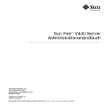
Switching Between the ALOM System
Controller and the System Console
The Netra 440 server features two management ports, labeled SERIAL MGT and
NET MGT, located on the server’s back panel. If the system console is directed to use
the serial management and network management ports (its default configuration),
these ports provide access to both the system console and the ALOM system
controller, each on a separate “channel” (see FIGURE 1-4).
System Console
ok
#
NET MGT
or SERIAL MGT
Port
console
#.
sc>
ALOM System Controller
FIGURE 1-4
Separate System Console and System Controller “Channels”
If the system console is configured to be accessible from the serial management and
network management ports, when you connect through one of these ports you can
access either the ALOM command-line interface or the system console. You can
switch between the ALOM system controller and the system console at any time, but
you cannot access both at the same time from a single terminal or shell tool.
Chapter 1
Configuring the System Console
15
The prompt displayed on the terminal or shell tool tells you which “channel” you
are accessing:
■
The # or % prompt indicates that you are at the system console and that the
Solaris OS is running.
■
The ok prompt indicates that you are at the system console and that the server is
running under OpenBoot firmware control.
■
The sc> prompt indicates that you are at the ALOM system controller.
Note – If no text or prompt appears, it may be the case that no console messages
were recently generated by the system. If this happens, pressing the terminal’s Enter
or Return key should produce a prompt.
To reach the system console from the ALOM system controller, type the console
command at the sc> prompt. To reach the ALOM system controller from the system
console, type the system controller escape sequence, which by default is #. (pound
period).
For more information, see the following:
■
■
■
■
■
“Communicating With the System” on page 1
“About the sc> Prompt” on page 8
“OpenBoot ok Prompt” on page 9
“Accessing the System Controller” on page 16
Advanced Lights Out Manager User’s Guide
Accessing the System Controller
The following sections describe ways of accessing the system controller.
Using the Serial Management Port
This procedure assumes that the system console is directed to use the serial
management and network management ports (the default configuration).
When you are accessing the system console using a device connected to the serial
management port, your first point of access is the ALOM system controller and its
sc> prompt. After connecting to the ALOM system controller, you can switch to the
system console itself.
16
Netra 440 Server System Administration Guide • August 2004
For more information about the ALOM system controller card, refer to the Netra 440
Server Product Overview (817-3881-xx) and the Advanced Lights Out Manager User’s
Guide (817-5481-xx).
▼ To Use the Serial Management Port
1. Ensure that the serial port on your connecting device is set to the following
parameters:
■
■
■
■
■
9600 baud
8 bits
No parity
1 stop bit
No handshaking
2. Establish an ALOM system controller session.
See Advanced Lights Out Manager User’s Guide (817-5481-xx) for instructions.
3. To connect to the system console, at the ALOM system controller command
prompt, type:
sc> console
The console command switches you to the system console.
4. To switch back to the sc> prompt, type the #. escape sequence.
ok #. [characters are not echoed to the screen]
For instructions on how to use the ALOM system controller, see the Advanced Lights
Out Manager User’s Guide (817-5481-xx).
Activating the Network Management Port
You must assign an Internet Protocol (IP) address to the network management port
before you can use it. If you are configuring the network management port for the
first time, you must first connect to the ALOM system controller using the serial
management port and assign an IP address to the network management port. You
can either assign an IP address manually, or you can configure the port to obtain an
IP address using the Dynamic Host Configuration Protocol (DHCP) from another
server.
Chapter 1
Configuring the System Console
17
Data centers frequently devote a separate subnet to system management. If your
data center has such a configuration, connect the network management port to this
subnet.
Note – The network management port is a 10BASE-T port. The IP address assigned
to the network management port is a unique IP address, separate from the main
Netra 440 server IP address, and is dedicated for use only with the ALOM system
controller. For more information, see the Netra 440 Server Product Overview.
▼ To Activate the Network Management Port
1. Connect an Ethernet cable to the network management port.
2. Log in to the ALOM system controller through the serial management port.
For more information about connecting to the serial management port, see
“Accessing the System Controller” on page 16.
3. Type one of the following commands:
■
If your network uses static IP addresses, type:
sc>
sc>
sc>
sc>
■
setsc
setsc
setsc
setsc
if_network true
netsc_ipaddr ip-address
netsc_ipnetmask ip-address
netsc_ipgateway ip-address
If your network uses Dynamic Host Configuration Protocol (DHCP), type:
sc> setsc netsc_dhcp
4. Enter the following so that the new settings will take affect:
sc> resetsc
5. To verify the network settings, type:
sc> shownetwork
6. Log out of the ALOM system controller session.
18
Netra 440 Server System Administration Guide • August 2004
To connect through the network management port, use the telnet command to the
IP address you specified in Step 3 of the preceding procedure.
Accessing the System Console Through a
Terminal Server
The following procedure assumes that you are accessing the system console by
connecting a terminal server to the serial management port (SERIAL MGT) of the
Netra 440 server.
▼ To Access The System Console Through a Terminal Server
1. Complete the physical connection from the serial management port to your
terminal server.
The serial management port on the Netra 440 server is a data terminal equipment
(DTE) port. The pinouts for the serial management port correspond with the pinouts
for the RJ-45 ports on the Serial Interface Breakout Cable supplied by Cisco for use
with the Cisco AS2511-RJ terminal server. If you use a terminal server made by
another manufacturer, check that the serial port pinouts of the Netra 440 server
match those of the terminal server you plan to use.
If the pinouts for the server serial ports correspond with the pinouts for the RJ-45
ports on the terminal server, you have two connection options:
■
Connect a serial interface breakout cable directly to the Netra 440 server. See
“Accessing the System Controller” on page 16.
■
Connect a serial interface breakout cable to a patch panel and use the straightthrough patch cable (supplied by Sun) to connect the patch panel to the server.
Chapter 1
Configuring the System Console
19
Terminal server
Straight-through cable
Patch panel
Patch cable to serial management port
Netra 440
server
FIGURE 1-5
Patch Panel Connection Between a Terminal Server and a Netra 440 Server
If the pinouts for the serial management port do not correspond with the pinouts for
the RJ-45 ports on the terminal server, you need to make a crossover cable that takes
each pin on the Netra 440 server serial management port to the corresponding pin in
the terminal server’s serial port.
TABLE 1-3 shows the crossovers that the cable must perform.
TABLE 1-3
20
Pin Crossovers for Connecting to a Typical Terminal Server
Netra 440 Serial Port (RJ-45 Connector) Pin
Terminal Server Serial Port Pin
Pin 1 (RTS)
Pin 1 (CTS)
Pin 2 (DTR)
Pin 2 (DSR)
Pin 3 (TXD)
Pin 3 (RXD)
Pin 4 (Signal Ground)
Pin 4 (Signal Ground)
Pin 5 (Signal Ground)
Pin 5 (Signal Ground)
Pin 6 (RXD)
Pin 6 (TXD)
Pin 7 (DSR /DCD)
Pin 7 (DTR)
Pin 8 (CTS)
Pin 8 (RTS)
Netra 440 Server System Administration Guide • August 2004
2. Open a terminal session on the connecting device, and type:
% telnet IP-address-of-terminal-server port-number
For example, for a Netra 440 server connected to port 10000 on a terminal server
whose IP address is 192.20.30.10, you would type:
% telnet 192.20.30.10 10000
3. If you want to use TTYB instead of the serial management port, do the following:
a. Redirect the system console by changing OpenBoot configuration variables.
At the ok prompt, type the following commands:
ok setenv input-device ttyb
ok setenv output-device ttyb
Note – Redirecting the system console does not redirect POST output. You can only
view POST messages from the serial and network management port devices.
Note – There are many other OpenBoot configuration variables. Although these
variables do not affect which hardware device is used to access the system console,
some of them affect which diagnostic tests the system runs and which messages the
system displays at its console. For details, refer to the Netra 440 Server Diagnostics
and Troubleshooting Guide (817-3886-xx).
b. To cause the changes to take effect, power off the system. Type:
ok power-off
The system permanently stores the parameter changes and powers off.
Note – You can also power off the system using the front panel Power button.
c. Connect the null modem serial cable to the ttyb port on the Netra 440 server.
If required, use the DB-9 or DB-25 cable adapter supplied with the server.
Chapter 1
Configuring the System Console
21
d. Power on the system.
Refer to the Netra 440 Server Installation Guide for power-on procedures.
Continue with your installation or diagnostic test session as appropriate. When you
are finished, end your session by typing the terminal server’s escape sequence and
exit the window.
For more information about connecting to and using the ALOM system controller,
refer to the Advanced Lights Out Manager User’s Guide.
If you have redirected the system console to ttyb and want to change the system
console settings back to use the serial management and network management ports,
see “System Console OpenBoot Configuration Variable Settings” on page 31.
Accessing the System Console Through a TIP
Connection
This procedure assumes that you are accessing the Netra 440 server system console
by connecting the serial port of another Sun system to the serial management port
(SERIAL MGT) of the Netra 440 server (FIGURE 1-6).
Serial management port
Serial port
TIP connection
FIGURE 1-6
22
Another Sun system
TIP Connection Between a Netra 440 Server and Another Sun System
Netra 440 Server System Administration Guide • August 2004
▼ To Access the System Console Through the TIP Connection
1. Connect the RJ-45 serial cable and, if required, the DB-9 or DB-25 adapter
provided.
The cable and adapter connect between another Sun system’s serial port (typically
ttyb) and the serial management port on the back panel of the Netra 440 server.
Pinouts, part numbers, and other details about the serial cable and adapter are
provided in the Netra 440 Server Service Manual (817-3883-xx).
2. Ensure that the /etc/remote file on the Sun system contains an entry for
hardwire.
Most releases of Solaris OS software shipped since 1992 contain an /etc/remote
file with the appropriate hardwire entry. However, if the Sun system is running an
older version of Solaris OS software, or if the /etc/remote file has been modified,
you might need to edit it. See “Modifying the /etc/remote File” on page 25 for
details.
3. In a shell tool window on the Sun system, type:
% tip hardwire
The Sun system responds by displaying:
connected
The shell tool is now a TIP window directed to the Netra 440 server through the Sun
system’s serial port. This connection is established and maintained even when the
Netra 440 server is completely powered off or just starting up.
Note – Use a shell tool or a CDE terminal (such as dtterm), not a command tool.
Some TIP commands might not work properly in a command tool window.
4. If you want to use TTYB on the Netra 440 server instead of the serial management
port, do the following:
a. Redirect the system console by changing the OpenBoot configuration variables.
At the ok prompt on the Netra 440 server, type the following commands:
ok setenv input-device ttyb
ok setenv output-device ttyb
Chapter 1
Configuring the System Console
23
Note – You can only access the sc> prompt and view POST messages from either
the serial management port or the network management port.
Note – There are many other OpenBoot configuration variables. Although these
variables do not affect which hardware device is used to access the system console,
some of them affect which diagnostic tests the system runs and which messages the
system displays at its console. For details, refer to the Netra 440 Server Diagnostics
and Troubleshooting Guide (817-3886-xx).
b. To cause the changes to take effect, power off the system. Type:
ok power-off
The system permanently stores the parameter changes and powers off.
Note – You can also power off the system using the front panel Power button.
c. Connect the null modem serial cable to the ttyb port on the Netra 440 server.
If required, use the DB-9 or DB-25 cable adapter supplied with the server.
d. Power on the system.
Refer to the Netra 440 Server Installation Guide for power-on procedures.
Continue with your installation or diagnostic test session as appropriate. When you
are finished using the TIP window, end your TIP session by typing ~. (the tilde
symbol followed by a period) and exit the window. For more information about TIP
commands, see the TIP man page.
For more information about connecting to and using the ALOM system controller,
see the Advanced Lights Out Manager User’s Guide (817-5481-xx).
If you have redirected the system console to ttyb and want to change the system
console settings back to use the serial management and network management ports,
see “System Console OpenBoot Configuration Variable Settings” on page 31.
24
Netra 440 Server System Administration Guide • August 2004
Modifying the /etc/remote File
This procedure might be necessary if you are accessing the Netra 440 server using a
TIP connection from a Sun system running an older version of the Solaris OS
software. You might also need to perform this procedure if the /etc/remote file on
the Sun system has been altered and no longer contains an appropriate hardwire
entry.
This procedure assumes that you are logged in as superuser to the system console of
a Sun system that you intend to use to establish a TIP connection to the Netra 440
server.
▼ To Modify the /etc/remote File
1. Determine the release level of Solaris OS software installed on the Sun system.
Type:
# uname -r
The system responds with a release number.
2. Do one of the following, depending on the number displayed.
■
If the number displayed by the uname -r command is 5.0 or higher:
The Solaris OS software shipped with an appropriate entry for hardwire in the
/etc/remote file. If you have reason to suspect that this file was altered and the
hardwire entry modified or deleted, check the entry against the following
example, and edit it as needed.
hardwire:\
:dv=/dev/term/b:br#9600:el=^C^S^Q^U^D:ie=%$:oe=^D:
Note – If you intend to use the Sun system’s serial port A rather than serial port B,
edit this entry by replacing /dev/term/b with /dev/term/a.
■
If the number displayed by the uname -r command is less than 5.0:
Check the /etc/remote file and add the following entry, if it does not already
exist.
hardwire:\
:dv=/dev/ttyb:br#9600:el=^C^S^Q^U^D:ie=%$:oe=^D:
Chapter 1
Configuring the System Console
25
Note – If you intend to use the Sun system’s serial port A rather than serial port B,
edit this entry by replacing /dev/ttyb with /dev/ttya.
The /etc/remote file is now properly configured. Continue establishing a TIP
connection to the Netra 440 server system console. See “Accessing the System
Console Through a TIP Connection” on page 22.
If you have redirected the system console to ttyb and want to change the system
console settings back to use the serial management and network management ports,
see “System Console OpenBoot Configuration Variable Settings” on page 31.
Accessing the System Console Through an
Alphanumeric Terminal
This procedure assumes that you are accessing the Netra 440 server system console
by connecting the serial port of an alphanumeric terminal to the serial management
port (SERIAL MGT) of the Netra 440 server.
▼ To Access the System Console Through an Alphanumeric
Terminal
1. Attach one end of the serial cable to the alphanumeric terminal’s serial port.
Use a null modem serial cable or an RJ-45 serial cable and null modem adapter.
Connect this cable to the terminal’s serial port connector.
2. Attach the opposite end of the serial cable to the serial management port on the
Netra 440 server.
3. Connect the alphanumeric terminal’s power cord to an AC outlet.
4. Set the alphanumeric terminal to receive:
■
■
■
■
■
9600 baud
8 bits
No parity
1 stop bit
No handshake protocol
Refer to the documentation accompanying your terminal for information about how
to configure the terminal.
26
Netra 440 Server System Administration Guide • August 2004
5. If you want to use ttyb instead of the serial management port, do the following:
a. Redirect the system console by changing the OpenBoot configuration variables.
At the ok prompt, type the following commands:
ok setenv input-device ttyb
ok setenv output-device ttyb
Note – You can only access the sc> prompt and view POST messages from either
the serial management port or the network management port.
Note – There are many other OpenBoot configuration variables. Although these
variables do not affect which hardware device is used to access the system console,
some of them affect which diagnostic tests the system runs and which messages the
system displays at its console. For details, refer to the Netra 440 Server Diagnostics
and Troubleshooting Guide (817-3886-xx).
b. To cause the changes to take effect, power off the system. Type:
ok power-off
The system permanently stores the parameter changes and powers off.
Note – You can also power off the system using the front panel Power button.
c. Connect the null modem serial cable to the ttyb port on the Netra 440 server.
If required, use the DB-9 or DB-25 cable adapter supplied with the server.
d. Power on the system.
Refer to the Netra 440 Server Installation Guide for power-on procedures.
You can issue system commands and view system messages using the alphanumeric
terminal. Continue with your installation or diagnostic procedure, as needed. When
you are finished, type the alphanumeric terminal’s escape sequence.
For more information about connecting to and using the ALOM system controller,
refer to the Advanced Lights Out Manager User’s Guide (817-5481-xx).
If you have redirected the system console to ttyb and want to change the system
console settings back to use the serial management and network management ports,
see “System Console OpenBoot Configuration Variable Settings” on page 31.
Chapter 1
Configuring the System Console
27
Verifying Serial Port Settings on TTYB
This procedure lets you verify the baud rate and other serial port settings used by
the Netra 440 server to communicate with a device attached to its ttyb port.
Note – The serial management port always operates at 9600 baud, 8 bits, with no
parity and 1 stop bit.
You must be logged in to the Netra 440 server, and the server must be running
Solaris OS software.
▼ To Verify the Serial Port Settings on TTYB
1. Open a shell tool window.
2. Type:
# eeprom | grep ttyb-mode
3. Look for the following output:
ttyb-mode = 9600,8,n,1,-
This line indicates that the Netra 440 server’s serial port ttyb is configured for:
■
■
■
■
■
9600 baud
8 bits
No parity
1 stop bit
No handshake protocol
For more information about serial port settings, see the eeprom man page. For more
information about the ttyb-mode OpenBoot configuration variable, see
Appendix A.
28
Netra 440 Server System Administration Guide • August 2004
Accessing the System Console Through a Local
Graphics Monitor
After initial system installation, you can install a local graphics monitor and
configure it to access the system console. You cannot use a local graphics monitor to
perform initial system installation, nor can you use a local graphics monitor to view
power-on self-test (POST) messages.
To install a local graphics monitor, you must have:
■
■
■
■
A
A
A
A
supported PCI-based graphics frame buffer card and software driver.
monitor with appropriate resolution to support the frame buffer
Sun-compatible USB keyboard (Sun USB Type–6 keyboard)
Sun-compatible USB mouse (Sun USB mouse) and mouse pad
▼ To Access the System Console Through a Local Graphics
Monitor
1. Install the graphics card into an appropriate PCI slot.
Installation must be performed by a qualified service provider. For further
information, refer to the Netra 440 Server Service Manual or contact your qualified
service provider.
2. Attach the monitor’s video cable to the graphics card’s video port.
Tighten the thumbscrews to secure the connection.
3. Connect the monitor’s power cord to an AC outlet.
4. Connect the USB keyboard cable to one USB port and the USB mouse cable to the
other USB port on the Netra 440 server back panel (FIGURE 1-2).
5. Get to the ok prompt.
For more information, see “Getting to the ok Prompt” on page 13.
6. Set OpenBoot configuration variables appropriately.
From the existing system console, type:
ok setenv input-device keyboard
ok setenv output-device screen
Chapter 1
Configuring the System Console
29
Note – There are many other OpenBoot configuration variables. Although these
variables do not affect which hardware device is used to access the system console,
some of them affect which diagnostic tests the system runs and which messages the
system displays at its console. For details, refer to the Netra 440 Server Diagnostics
and Troubleshooting Guide (817-3886-xx).
7. To cause the changes to take effect, type:
ok reset-all
The system stores the parameter changes, and boots automatically when the
OpenBoot configuration variable auto-boot? is set to true (its default value).
Note – To store parameter changes, you can also power cycle the system using the
front panel Power button.
You can issue system commands and view system messages using your local
graphics monitor. Continue with your installation or diagnostic procedure, as
needed.
If you want to redirect the system console back to the serial management and
network management ports, see “System Console OpenBoot Configuration Variable
Settings” on page 31.
30
Netra 440 Server System Administration Guide • August 2004
System Console OpenBoot
Configuration Variable Settings
The Netra 440 system console is directed to the serial management and network
management ports (SERIAL MGT and NET MGT) by default. However, you can
redirect the system console to the serial DB-9 port (TTYB), or to a local graphics
monitor, keyboard, and mouse. You can also redirect the system console back to the
serial management and network management ports.
Certain OpenBoot configuration variables control from where system console input
is taken and to where its output is directed. The table below shows how to set these
variables in order to use the serial management and network management ports,
TTYB, or a local graphics monitor as the system console connection.
TABLE 1-4
OpenBoot Configuration Variables That Affect the System Console
Setting for Sending System Console Output to:
OpenBoot Configuration
Variable Name
Serial and
Network
Management Ports
Serial Port (TTYB)*
Local Graphics
Monitor/USB
Keyboard and
Mouse*
output-device
ttya
ttyb
screen
input-device
ttya
ttyb
keyboard
* POST output will still be directed to the serial management port, as POST has no mechanism to direct its output
to a graphics monitor.
The serial management port and network management port are present in the
OpenBoot configuration variables as ttya. However, the serial management port
does not function as a standard serial connection. If you want to connect a
conventional serial device (such as a printer) to the system, you must connect it to
TTYB, not the serial management port. Refer to the Netra 440 Server Product Overview
for more information (817-3881-xx).
It is important to note that the sc> prompt and POST messages are only available
through the serial management port and network management port. In addition, the
ALOM system controller console command is ineffective when the system console
is redirected to ttyb or a local graphics monitor.
In addition to the OpenBoot configuration variables described in TABLE 1-4, there are
other variables that affect and determine system behavior. These variables, which are
stored on the system configuration card, are discussed in more detail in the Netra 440
Server Product Overview (817-3881-xx).
Chapter 1
Configuring the System Console
31
32
Netra 440 Server System Administration Guide • August 2004
CHAPTER
2
Managing RAS Features and System
Firmware
This chapter describes how to manage reliability, availability, and serviceability
(RAS) features and system firmware, including Sun Advanced Lights Out Manager
(ALOM) system controller, automatic system recovery (ASR), and the hardware
watchdog mechanism. In addition, this chapter describes how to unconfigure and
reconfigure a device manually, and introduces multipathing software.
This chapter contains the following sections:
■
“ALOM System Controller” on page 34
■
■
■
■
■
“ALOM System Controller” on page 34
“Logging In To the ALOM System Controller” on page 34
“About the scadm Utility” on page 35
“To View Environmental Information” on page 36
“Controlling the Locator LED” on page 37
■
“OpenBoot Emergency Procedures” on page 39
■
“Automatic System Recovery” on page 41
■
■
■
■
“Enabling and Disabling Automatic System Recovery” on page 44
“To Disable Automatic System Recovery” on page 45
“Obtaining Automatic System Recovery Information” on page 46
“Unconfiguring and Reconfiguring Devices” on page 46
“To Unconfigure a Device Manually” on page 46
“To Reconfigure a Device Manually” on page 48
“Enabling the Hardware Watchdog Mechanism and Its Options” on page 49
“Multipathing Software” on page 50
■
■
■
■
Note – This chapter does not cover detailed troubleshooting and diagnostic
procedures. For information about fault isolation and diagnostic procedures, refer to
the Netra 440 Server Diagnostics and Troubleshooting Guide (817-3886-xx).
33
ALOM System Controller
The ALOM system controller supports a total of five concurrent sessions per server:
four connections available through the network management port and one
connection through the serial management port.
Note – Some of the ALOM system controller commands are also available through
the Solaris scadm utility. For more information, refer to the Advanced Lights Out
Manager User’s Guide (817-5481-xx).
After you log in to your ALOM account, the ALOM system controller command
prompt (sc>) appears, and you can enter ALOM system controller commands. If the
command you want to use has multiple options, you can either enter the options
individually or grouped together, as shown in the following example. The
commands are identical.
sc> poweroff -f -y
sc> poweroff -fy
Logging In To the ALOM System Controller
All environmental monitoring and control is handled by the ALOM system
controller. The ALOM system controller command prompt (sc>) provides you with
a way of interacting with the system controller. For more information about the sc>
prompt, see “About the sc> Prompt” on page 8.
For instructions on connecting to the ALOM system controller, see:
■
■
“Accessing the System Controller” on page 16
“Activating the Network Management Port” on page 17
Note – This procedure assumes that the system console is directed to use the serial
management and network management ports (the default configuration).
34
Netra 440 Server System Administration Guide • August 2004
▼ To Log In To the ALOM System Controller
1. If you are logged in to the system console, type #. to get to the sc> prompt.
Press the pound sign key, followed by the period key. Then press the Return key.
2. At the ALOM login prompt, enter the login name and press Return.
The default login name is admin.
Sun(tm) Advanced Lights Out Manager 1.3
Please login: admin
3. At the password prompt, enter the password and press Return twice to get to the
sc> prompt.
Please Enter password:
sc>
Note – There is no default password. You must assign a password during initial
system configuration. For more information, refer to your Netra 440 Server
Installation Guide (817-3882-xx) and Advanced Lights Out Manager User’s Guide (8175481-xx).
Caution – In order to provide optimum system security, best practice is to change
the default system login name and password during initial setup.
Using the ALOM system controller, you can monitor the system, turn the Locator
LED on and off, or perform maintenance tasks on the ALOM system controller card
itself. For more information, refer to the Advanced Lights Out Manager User’s Guide
(817-5481-xx).
About the scadm Utility
The System Controller Administration (scadm) utility, which is part of the Solaris
OS, enables you to perform many ALOM tasks while logged in to the host server.
The scadm commands control several functions. Some functions allow you to view
or set ALOM environment variables.
Chapter 2
Managing RAS Features and System Firmware
35
Note – Do not use the scadm utility while SunVTS™ diagnostics are running. See
your SunVTS documentation for more information.
You must be logged in to the system as root to use the scadm utility. The scadm
utility uses the following syntax:
# scadm command
The scadm utility sends its output to stdout. You can also use scadm in scripts to
manage and configure ALOM from the host system.
For more information about the scadm utility, refer to the following:
■
■
scadm man page
Advanced Lights Out Manager User’s Guide (817-5481-xx)
▼ To View Environmental Information
1. Log in to the ALOM system controller.
2. Use the showenvironment command to display a snapshot of the server’s
environmental status.
sc> showenvironment
=============== Environmental Status ===============
-----------------------------------------------------------------------------System Temperatures (Temperatures in Celsius):
-----------------------------------------------------------------------------Sensor
Status
Temp LowHard LowSoft LowWarn HighWarn HighSoft HighHard
-----------------------------------------------------------------------------C0.P0.T_CORE
OK
48
-20
-10
0
97
102
120
C1.P0.T_CORE
OK
53
-20
-10
0
97
102
120
C2.P0.T_CORE
OK
49
-20
-10
0
97
102
120
C3.P0.T_CORE
OK
57
-20
-10
0
97
102
120
C0.T_AMB
OK
28
-20
-10
0
70
82
87
C1.T_AMB
OK
33
-20
-10
0
70
82
87
C2.T_AMB
OK
27
-20
-10
0
70
82
87
C3.T_AMB
OK
28
-20
-10
0
70
82
87
MB.T_AMB
OK
32
-18
-10
0
65
75
85
...
36
Netra 440 Server System Administration Guide • August 2004
The information this command can display includes temperature, power supply
status, front panel LED status, system control keyswitch position, and so on. The
display uses a format similar to that of the UNIX command prtdiag(1m).
Note – Some environmental information might not be available when the server is
in standby mode.
Note – You do not need ALOM system controller user permissions to use this
command.
The showenvironment command has one option: -v. If you use this option, ALOM
returns more detailed information about the host server’s status, including warning
and shutdown thresholds.
Controlling the Locator LED
You can control the Locator LED either from the Solaris command prompt or from
the sc> prompt.
● To turn on the Locator LED, do one of the following:
■
In the Solaris OS, log as superuser and type the following command:
# /usr/sbin/setlocator -n
Locator LED is on.
■
From the ALOM system controller command prompt, type:
sc> setlocator on
Locator LED is on.
Chapter 2
Managing RAS Features and System Firmware
37
● To turn off the Locator LED, do one of the following:
■
In the Solaris OS, log in as superuser and type the following command:
# /usr/sbin/setlocator -f
Locator LED is off.
■
From the ALOM system controller command prompt, type:
sc> setlocator off
Locator LED is off.
● To display the state of the Locator LED, do one of the following:
■
In the Solaris OS, log in as superuser and type the following command:
# /usr/sbin/showlocator
Locator LED is on.
■
From the ALOM system controller command prompt, type:
sc> showlocator
Locator LED is on.
Note – You do not need user permissions to use the setlocator and
showlocator commands.
38
Netra 440 Server System Administration Guide • August 2004
OpenBoot Emergency Procedures
The introduction of Universal Serial Bus (USB) keyboards with the newest Sun
systems has made it necessary to change some of the OpenBoot emergency
procedures. Specifically, the Stop-N, Stop-D, and Stop-F commands that were
available on systems with non-USB keyboards are not supported on systems that use
USB keyboards, such as the Netra 440 server. If you are familiar with the earlier
(non-USB) keyboard functionality, this section describes the analogous OpenBoot
emergency procedures available in newer systems that use USB keyboards.
OpenBoot Emergency Procedures for Systems
With Non-USB Keyboards
TABLE 2-1 summarizes the Stop key command functions for systems that use
standard (non-USB) keyboards.
TABLE 2-1
Stop Key Command Functions for Systems With Standard (Non-USB)
Keyboards
Standard (Non-USB)
Keyboard Command
Description
Stop
Bypass POST. This command does not depend on security
mode.
Stop-A
Abort.
Stop-D
Enter the diagnostic mode (set diag-switch? to true).
Stop-F
Enter Forth on ttya instead of probing. Use fexit to
continue with the initialization sequence. Useful when there
is a hardware problem.
Stop-N
Reset OpenBoot configuration variables to their default
values.
Chapter 2
Managing RAS Features and System Firmware
39
OpenBoot Emergency Procedures for Systems
With USB Keyboards
The following sections describe how to perform the functions of the Stop commands
on systems that use USB keyboards, such as the Netra 440 server. These same
functions are available through Sun Advanced Lights Out Manager (ALOM) system
controller software.
Stop-A Functionality
Stop-A (Abort) key sequence works the same as it does on systems with standard
keyboards, except that it does not work during the first few seconds after the server
is reset. In addition, you can issue the ALOM system controller break command.
For more information, see “Reaching the ok Prompt” on page 10.
Stop-N Functionality
Stop-N functionality is not available. However, the Stop-N functionality can be
closely emulated by completing the following steps, provided the system console is
configured to be accessible using either the serial management port or the network
management port.
▼ To Restore OpenBoot Configuration Defaults
1. Log in to the ALOM system controller.
2. Type the following command:
sc> bootmode reset_nvram
sc>
SC Alert: SC set bootmode to reset_nvram, will expire
20030218184441.
bootmode
Bootmode: reset_nvram
Expires TUE FEB 18 18:44:41 2003
This command resets the default OpenBoot configuration variables.
40
Netra 440 Server System Administration Guide • August 2004
3. To reset the system, type the following command:
sc> reset
Are you sure you want to reset the system [y/n]?
sc> console
y
4. To view console output as the system boots with default OpenBoot configuration
variables, switch to console mode.
sc> console
ok
5. Type set-defaults to discard any customized IDPROM values and to restore
the default settings for all OpenBoot configuration variables.
Stop-F Functionality
The Stop-F functionality is not available on systems with USB keyboards.
Stop-D Functionality
The Stop-D (Diags) key sequence is not supported on systems with USB keyboards.
However, the Stop-D functionality can be closely emulated by turning the system
control keyswitch to the Diagnostics position. For more information, refer to the
Netra 440 Server Product Overview (817-3881-xx).
In addition, you can emulate Stop-D functionality using the ALOM system
controller bootmode diag command. For more information, refer to the Advanced
Lights Out Manager User’s Guide (817-5481-xx).
Automatic System Recovery
The system provides for automatic system recovery (ASR) from failures in memory
modules or PCI cards.
Automatic system recovery functionality enables the system to resume operation
after experiencing certain nonfatal hardware faults or failures. When ASR is enabled,
the system’s firmware diagnostics automatically detect failed hardware components.
Chapter 2
Managing RAS Features and System Firmware
41
An auto-configuring capability designed into the OpenBoot firmware enables the
system to unconfigure failed components and to restore system operation. As long
as the system is capable of operating without the failed component, the ASR features
enable the system to reboot automatically, without operator intervention.
Note – ASR is not activated until you enable it. See “Enabling and Disabling
Automatic System Recovery” on page 44.
For more information about ASR, refer to the Netra 440 Server Diagnostics and
Troubleshooting Guide (817-3886-xx).
Auto-Boot Options
The OpenBoot firmware stores a configuration variable on the system configuration
card (SCC) called auto-boot?, which controls whether the firmware will
automatically boot the operating system after each reset. The default setting for Sun
platforms is true.
Normally, if a system fails power-on diagnostics, auto-boot? is ignored and the
system does not boot unless an operator boots the system manually. A manual boot
is obviously not acceptable for booting a system in a degraded state. Therefore, the
Netra 440 server OpenBoot firmware provides a second setting,
auto-boot-on-error?. This setting controls whether the system will attempt a
degraded boot when a subsystem failure is detected. Both the auto-boot? and
auto-boot-on-error? switches must be set to true to enable an automatic
degraded boot. To set the switches, type:
ok setenv auto-boot? true
ok setenv auto-boot-on-error? true
Note – The default setting for auto-boot-on-error? is false. Therefore, the
system will not attempt a degraded boot unless you change this setting to true. In
addition, the system will not attempt a degraded boot in response to any fatal
nonrecoverable error, even if degraded booting is enabled. For examples of fatal
nonrecoverable errors, see “Error Handling Summary” on page 43.
42
Netra 440 Server System Administration Guide • August 2004
Error Handling Summary
Error handling during the power-on sequence falls into one of the following three
cases:
■
If no errors are detected by POST or OpenBoot Diagnostics, the system attempts
to boot if auto-boot? is true.
■
If only nonfatal errors are detected by POST or OpenBoot Diagnostics, the system
attempts to boot if auto-boot? is true and auto-boot-on-error? is true.
Nonfatal errors include the following:
■
Ultra-4 SCSI subsystem failure. In this case, a working alternate path to the
boot disk is required. For more information, see “Multipathing Software” on
page 50.
■
Ethernet interface failure.
■
USB interface failure.
■
Serial interface failure.
■
PCI card failure.
■
Memory failure. Given a failed DIMM, the firmware will unconfigure the entire
logical bank associated with the failed module. Another nonfailing logical
bank must be present in the system for the system to attempt a degraded boot.
For more information, refer to the Netra 440 Server Product Overview (817-3881xx).
Note – If POST or OpenBoot Diagnostics detects a nonfatal error associated with the
normal boot device, the OpenBoot firmware automatically unconfigures the failed
device and tries the next-in-line boot device, as specified by the diag-device
configuration variable.
■
If a fatal error is detected by POST or OpenBoot Diagnostics, the system does not
boot regardless of the settings of auto-boot? or auto-boot-on-error?. Fatal
nonrecoverable errors include the following:
■
■
■
■
■
■
Any CPU failed
All logical memory banks failed
Flash RAM cyclical redundancy check (CRC) failure
Critical field-replaceable unit (FRU) PROM configuration data failure
Critical system configuration card (SCC) read failure
Critical application-specific integrated circuit (ASIC) failure
For more information about troubleshooting fatal errors, refer to the Netra 440 Server
Diagnostics and Troubleshooting Guide (817-3886-xx).
Chapter 2
Managing RAS Features and System Firmware
43
Reset Scenarios
Three OpenBoot configuration variables, diag-switch?, obdiag-trigger, and
post-trigger, control whether the system runs firmware diagnostics in response
to system reset events.
The standard system reset protocol bypasses POST and OpenBoot Diagnostics
completely unless the variable diag-switch? is set to true, or the system control
keyswitch is in the Diagnostics position. The default setting for this variable is
false. Therefore, to enable ASR, which relies on firmware diagnostics to detect
faulty devices, you must change this setting to true. For instructions, see “Enabling
and Disabling Automatic System Recovery” on page 44.
To control which reset events, if any, automatically initiate firmware diagnostics, the
OpenBoot firmware provides variables called obdiag-trigger and
post-trigger. For detailed explanations of these variables and their uses, refer to
the Netra 440 Server Diagnostics and Troubleshooting Guide (817-3886-xx).
Automatic System Recovery User Commands
The OpenBoot commands .asr, asr-disable, and asr-enable are available for
obtaining ASR status information and for manually unconfiguring or reconfiguring
system devices. For more information, see:
■
■
■
“Unconfiguring and Reconfiguring Devices” on page 46
“To Reconfigure a Device Manually” on page 48
“Obtaining Automatic System Recovery Information” on page 46
Enabling and Disabling Automatic System
Recovery
The automatic system recovery (ASR) feature is not activated until you enable it at
the system ok prompt.
▼ To Enable Automatic System Recovery
1. At the ok prompt, type:
ok setenv diag-switch? true
ok setenv auto-boot? true
ok setenv auto-boot-on-error? true
44
Netra 440 Server System Administration Guide • August 2004
2. Set the obdiag-trigger variable to any combination of power-on-reset,
error-reset, and user-reset. For example, type:
ok setenv obdiag-trigger power-on-reset error-reset
Note – For more information about OpenBoot configuration variables, refer to the
Netra 440 Server Diagnostics and Troubleshooting Guide (817-3886-xx).
3. To cause the parameter changes to take effect, type:
ok reset-all
The system permanently stores the parameter changes and boots automatically
when the OpenBoot configuration variable auto-boot? is set to true (its default
value).
Note – To store parameter changes, you can also power cycle the system using the
front panel Power button.
▼ To Disable Automatic System Recovery
1. At the ok prompt, type:
ok setenv auto-boot-on-error? false
2. To cause the parameter change to take effect, type:
ok reset-all
The system permanently stores the parameter change.
Note – To store parameter changes, you can also power cycle the system using the
front panel Power button.
After you disable the automatic system recovery (ASR) feature, it is not activated
again until you enable it at the system ok prompt.
Chapter 2
Managing RAS Features and System Firmware
45
Obtaining Automatic System Recovery
Information
Use the following procedure to retrieve information about the status of the
automatic system recovery (ASR) feature.
● At the ok prompt, type:
ok .asr
In the .asr command output, any devices marked disabled have been manually
unconfigured using the asr-disable command. The .asr command also lists
devices that have failed firmware diagnostics and have been automatically
unconfigured by the OpenBoot ASR feature.
For more information, see:
■
■
■
■
■
“Automatic System Recovery” on page 41
“Enabling and Disabling Automatic System Recovery” on page 44
“To Disable Automatic System Recovery” on page 45
“Unconfiguring and Reconfiguring Devices” on page 46
“To Reconfigure a Device Manually” on page 48
Unconfiguring and Reconfiguring
Devices
To support a degraded boot capability, the OpenBoot firmware provides the
asr-disable command, which enables you to unconfigure system devices
manually. This command “marks” a specified device as disabled, by creating an
appropriate status property in the corresponding device tree node. By convention,
the Solaris OS does not activate a driver for any device so marked.
▼
To Unconfigure a Device Manually
1. At the ok prompt, type:
ok asr-disable device-identifier
46
Netra 440 Server System Administration Guide • August 2004
where the device-identifier is one of the following:
Any full physical device path, as reported by the OpenBoot show-devs
command
Any valid device alias, as reported by the OpenBoot devalias command
Any device identifier from TABLE 2-2
■
■
■
Note – The device identifiers are not case sensitive. You can type them as uppercase
or lowercase characters.
TABLE 2-2
Device Identifiers and Devices
Device Identifiers
Devices
cpu0-bank0, cpu0-bank1, cpu0-bank2, cpu0-bank3, ... cpu3bank0, cpu3-bank1, cpu3-bank2, cpu3-bank3
Memory banks 0–3 for each CPU
cpu0-bank*, cpu1-bank*, ... cpu3-bank*
All memory banks for each CPU
ob-ide
On-board IDE controller
ob-net0, ob-net1
On-board Ethernet controllers
ob-scsi
On-board Ultra-4 SCSI controller
pci-slot0, pci-slot1, ... pci-slot5
PCI slots 0–5
pci-slot*
All PCI slots
pci*
All on-board PCI devices (on-board
Ethernet, Ultra-4 SCSI) and all PCI slots
hba8, hba9
PCI bridge chips 0 and 1, respectively
ob-usb0, ob-usb1
USB devices
*
All devices
■
To determine full physical device paths, type:
ok show-devs
The show-devs command lists the system devices and displays the full path
name of each device.
■
To display a list of current device aliases, type:
ok devalias
Chapter 2
Managing RAS Features and System Firmware
47
■
To create your own device alias for a physical device, type:
ok devalias alias-name physical-device-path
where alias-name is the alias that you want to assign, and physical-device-path is the
full physical device path for the device.
Note – If you manually disable a device using asr-disable, and then assign a
different alias to the device, the device remains disabled even though the device
alias has changed.
2. To cause the parameter change to take effect, type:
ok reset-all
The system permanently stores the parameter change.
Note – To store parameter changes, you can also power cycle the system using the
front panel Power button.
▼
To Reconfigure a Device Manually
1. At the ok prompt, type:
ok asr-enable device-identifier
where the device-identifier is one of the following:
■
■
■
Any full physical device path, as reported by the OpenBoot show-devs
command
Any valid device alias, as reported by the OpenBoot devalias command
Any device identifier from TABLE 2-2
Note – The device identifiers are not case sensitive. You can type them as uppercase
or lowercase characters.
You can use the OpenBoot asr-enable command to reconfigure any device that
you previously unconfigured with the asr-disable command.
48
Netra 440 Server System Administration Guide • August 2004
Enabling the Hardware Watchdog
Mechanism and Its Options
For background information about the hardware watchdog mechanism and related
externally initiated reset (XIR) functionality, refer to the Netra 440 Server Product
Overview (817-3881-xx).
▼
To Enable the Hardware Watchdog Mechanism
1. Edit the /etc/system file to include the following entry:
set watchdog_enable = 1
2. Bring the system to the ok prompt by typing the following:
# init 0
3. Reboot the system so that the changes can take effect.
To have the hardware watchdog mechanism automatically reboot the system in case
of system hangs:
● At the ok prompt, type the following:
ok setenv error-reset-recovery boot
To generate automated crash dumps in case of system hangs:
● At the ok prompt, type the following:
ok setenv error-reset-recovery none
The sync option leaves you at the ok prompt in order to debug the system. For
more information about OpenBoot configuration variables, see Appendix A.
Chapter 2
Managing RAS Features and System Firmware
49
Multipathing Software
Multipathing software lets you define and control redundant physical paths to I/O
devices, such as storage devices and network interfaces. If the active path to a device
becomes unavailable, the software can automatically switch to an alternate path to
maintain availability. This capability is known as automatic failover. To take
advantage of multipathing capabilities, you must configure the server with
redundant hardware, such as redundant network interfaces or two host bus adapters
connected to the same dual-ported storage array.
For the Netra 440 server, three different types of multipathing software are available:
■
Solaris IP Network Multipathing software provides multipathing and
load-balancing capabilities for IP network interfaces.
■
VERITAS Volume Manager (VVM) software includes a feature called Dynamic
Multipathing (DMP), which provides disk multipathing as well as disk load
balancing to optimize I/O throughput.
■
Sun StorEdge™ Traffic Manager is an architecture fully integrated within the
Solaris OS (beginning with the Solaris 8 release) that enables I/O devices to be
accessed through multiple host controller interfaces from a single instance of the
I/O device.
For More Information
For information about setting up redundant hardware interfaces for networks, refer
to the Netra 440 Server Installation Guide (817-3882-xx).
For instructions on how to configure and administer Solaris IP Network
Multipathing, consult the IP Network Multipathing Administration Guide provided
with your specific Solaris release.
For information about VVM and its DMP feature, see “Volume Management
Software” on page 52 and refer to the documentation provided with the VERITAS
Volume Manager software.
For information about Sun StorEdge Traffic Manager, refer to the Netra 440 Server
Product Overview (817-3881-xx) and refer to your Solaris OS documentation.
50
Netra 440 Server System Administration Guide • August 2004
CHAPTER
3
Managing Disk Volumes
This chapter describes redundant array of independent disks (RAID) concepts, how
to manage disk volumes, and how to configure hardware mirroring using the
on-board Ultra-4 SCSI controller.
This chapter contains the following sections:
■
■
■
■
■
■
■
■
■
“Disk Volumes” on page 51
“Volume Management Software” on page 52
“RAID Technology” on page 54
“Hardware Disk Mirroring” on page 56
“Physical Disk Slot Numbers, Physical Device Names, and Logical Device
Names” on page 57
“To Create a Hardware Disk Mirror” on page 57
“To Delete a Hardware Disk Mirror” on page 59
“To Perform a Mirrored Disk Hot-Plug Operation” on page 61
“To Perform a Non-Mirrored Disk Hot-Swap Operation” on page 62
Disk Volumes
Disk volumes are logical disk devices comprising one or more physical disks or
partitions from several different disks.
Once you create a volume, the operating system uses and maintains the volume as if
it were a single disk. By providing this logical volume management layer, the
software overcomes the restrictions imposed by physical disk devices.
Sun’s volume management products also provide RAID data redundancy and
performance features. RAID is a technology that helps protect against disk and
hardware failures. Through RAID technology, volume management software is able
to provide high data availability, excellent I/O performance, and simplified
administration.
51
Volume Management Software
Volume management software lets you create disk volumes. Sun Microsystems offers
two different volume management applications for use on the Netra 440 server:
■
■
VERITAS Volume Manager (VVM) software
Solaris™ Volume Manager software
Sun’s volume management applications offer the following features:
■
Support for several types of RAID configurations, which provide varying degrees
of availability, capacity, and performance
■
Hot-spare facilities, which provide for automatic data recovery when disks fail
■
Performance analysis tools, which enable you to monitor I/O performance and
isolate bottlenecks
■
A graphical user interface (GUI), which simplifies storage management
■
Support for online resizing, which enables volumes and their file systems to grow
and shrink online
■
Online reconfiguration facilities, which let you change to a different RAID
configuration or modify characteristics of an existing configuration
VERITAS Dynamic Multipathing
VERITAS Volume Manager software actively supports multiported disk arrays. It
automatically recognizes multiple I/O paths to a particular disk device within an
array. Called Dynamic Multipathing (DMP), this capability provides increased
reliability by providing a path failover mechanism. If one connection to a disk is lost,
VVM continues to access the data over the remaining connections. This multipathing
capability also provides greater I/O throughput by automatically balancing the I/O
load uniformly across multiple I/O paths to each disk device.
Sun StorEdge Traffic Manager
A newer alternative to DMP that is also supported by the Netra 440 server is Sun
StorEdge Traffic Manager software. Sun StorEdge Traffic Manager is a server-based
dynamic path failover software solution, used to improve the overall availability of
business applications. Sun StorEdge Traffic Manager (previously known as
multiplexed input/output, or MPxIO) is included in the Solaris OS.
52
Netra 440 Server System Administration Guide • August 2004
The Sun StorEdge Traffic Manager software integrates multiple path I/O
capabilities, automatic load balancing, and path failover functions into one package
for Sun servers connected to supported Sun StorEdge systems. Sun StorEdge Traffic
Manager can provide you with increased system performance and availability for
building mission-critical storage area networks (SANs).
The Sun StorEdge Traffic Manager architecture provides the following capabilities:
■
Helps protect against I/O outages due to I/O controller failures. Should one I/O
controller fail, Sun StorEdge Traffic Manager automatically switches to an
alternate controller.
■
Increases I/O performance by load balancing across multiple I/O channels.
Sun StorEdge T3, Sun StorEdge 3510, and Sun StorEdge A5x00 storage arrays are all
supported by Sun StorEdge Traffic Manager on a Netra 440 server. Supported I/O
controllers are single and dual fibre-channel network adapters, including the
following:
■
■
■
■
PCI Single Fibre-Channel Host Adapter (Sun part number x6799A)
PCI Dual Fibre-Channel Network Adapter (Sun part number x6727A)
2GByte PCI Single Fibre-Channel Host Adapter (Sun part number x6767A)
2GByte PCI Dual Fibre-Channel Network Adapter (Sun part number x6768A)
Note – Sun StorEdge Traffic Manager is not supported for boot disks containing the
root (/) file system. You can use hardware mirroring or VVM instead. See “To
Create a Hardware Disk Mirror” on page 57 and “Volume Management Software”
on page 52.
For More Information
Refer to the documentation supplied with the VERITAS Volume Manager and
Solaris Volume Manager software. For more information about Sun StorEdge Traffic
Manager, refer to your Solaris system administration documentation.
Chapter 3
Managing Disk Volumes
53
RAID Technology
VERITAS Volume Manager and Solstice DiskSuite™ software support RAID
technology to optimize performance, availability, and cost per user. RAID
technology reduces recovery time in the event of file system errors, and increases
data availability even in the event of a disk failure. There are several levels of RAID
configurations that provide varying degrees of data availability with corresponding
trade-offs in performance and cost.
This section describes some of the most popular and useful of those configurations,
including:
■
■
■
■
■
Disk concatenation
Disk striping (RAID 0)
Disk mirroring (RAID 1)
Disk striping with parity (RAID 5)
Hot-spares
Disk Concatenation
Disk concatenation is a method for increasing logical volume size beyond the
capacity of one hard drive by creating one large volume from two or more smaller
drives. This lets you create arbitrarily large partitions.
FIGURE 3-1
Graphical Representation of Disk Concatenation
Using this method, the concatenated disks are filled with data sequentially, with the
second disk being written to when no space remains on the first, the third when no
space remains on the second, and so on.
54
Netra 440 Server System Administration Guide • August 2004
RAID 0: Disk Striping
Disk striping (RAID 0) is a technique for increasing system throughput by using
several hard drives in parallel. Whereas in non-striped disks the operating system
writes a single block to a single disk, in a striped arrangement, each block is divided
and portions of the data are written to different disks simultaneously.
FIGURE 3-2
Graphical Representation of Disk Striping
System performance using RAID 0 will be better than using RAID 1 or 5, but the
possibility of data loss is greater because there is no way to retrieve or reconstruct
data stored on a failed hard drive.
RAID 1: Disk Mirroring
Disk mirroring (RAID 1) is a technique that uses data redundancy—two complete
copies of all data stored on two separate disks—to protect against loss of data due to
disk failure. One logical volume is duplicated on two separate disks.
FIGURE 3-3
Graphical Representation of Disk Mirroring
Whenever the operating system needs to write to a mirrored volume, both disks are
updated. The disks are maintained at all times with exactly the same information.
When the operating system needs to read from the mirrored volume, it reads from
whichever disk is more readily accessible at the moment, which can result in
enhanced performance for read operations.
Chapter 3
Managing Disk Volumes
55
On the Netra 440 server, you can configure hardware disk mirroring using the onboard Ultra-4 SCSI controller. This provides higher performance than with
conventional software mirroring using volume management software. For more
information, see:
■
■
■
“To Create a Hardware Disk Mirror” on page 57
“To Delete a Hardware Disk Mirror” on page 59
“To Perform a Mirrored Disk Hot-Plug Operation” on page 61
RAID 1 offers the highest level of data protection, but storage costs are high, and
write performance compared to RAID 0 or RAID 5 is reduced since all data must be
stored twice.
RAID 5: Disk Striping With Parity
RAID 5 is an implementation of disk striping in which parity information is
included with each disk write. The advantage of this technique is that if any one
disk in a RAID 5 array fails, all the information about the failed drive can be
reconstructed from the data and parity on the remaining disks.
System performance using RAID 5 will fall between that of RAID 0 and RAID 1;
however, RAID 5 provides limited data redundancy. If more than one disk fails, all
data is lost.
Hot-Spares
In a hot-spares arrangement, one or more hard drives are installed in the system but
are unused during normal operation. This configuration is also referred to as hot
relocation. Should one of the active drives fail, the data on the failed disk is
automatically reconstructed and generated on a hot-spare disk, enabling the entire
data set to maintain its availability.
Hardware Disk Mirroring
On the Netra 440 server, the Ultra-4 SCSI controller supports internal hardware disk
mirroring using the Solaris OS raidctl utility.
A hardware disk mirror created under the raidctl utility behaves slightly
differently than one created using volume management software. Under a software
mirror, each device has its own entry in the virtual device tree, and read/write
operations are performed to both virtual devices. Under hardware disk mirroring,
56
Netra 440 Server System Administration Guide • August 2004
only one device (the master) appears in the device tree. The mirrored device (the
slave) is invisible to the operating system, and is accessed only by the Ultra-4 SCSI
controller.
Caution – Creating or restoring a disk mirror destroys all data previously stored on
the hard drive.
Physical Disk Slot Numbers, Physical Device
Names, and Logical Device Names
To perform a disk hot-swap procedure, you must know the physical or logical device
name for the drive that you want to install or remove. If your system encounters a
disk error, often you can find messages about failing or failed disks in the system
console. This information is also logged in the /var/adm/messages files.
These error messages typically refer to a failed hard drive by its physical device
name (such as /devices/pci@1f,700000/scsi@2/sd@1,0) or by its logical device
name (such as c1t1d0). In addition, some applications might report a disk slot
number (0 through 3).
You can use TABLE 3-1 to associate internal disk slot numbers with the logical and
physical device names for each hard drive.
TABLE 3-1
Disk Slot Numbers, Logical Device Names, and Physical Device Names
Disk Slot Number
Logical Device Name*
Physical Device Name
Slot 0
c1t0d0
/devices/pci@1f,700000/scsi@2/sd@0,0
Slot 1
c1t1d0
/devices/pci@1f,700000/scsi@2/sd@1,0
Slot 2
c1t2d0
/devices/pci@1f,700000/scsi@2/sd@2,0
Slot 3
c1t3d0
/devices/pci@1f,700000/scsi@2/sd@3,0
* The logical device names might appear differently on your system, depending on the number and type of
add-on disk controllers installed.
▼
To Create a Hardware Disk Mirror
1. Verify which hard drive corresponds with which logical device name and physical
device name.
See “Physical Disk Slot Numbers, Physical Device Names, and Logical Device
Names” on page 57.
Chapter 3
Managing Disk Volumes
57
To verify that a hardware disk mirror does not exist already, type:
# raidctl
No RAID volumes found.
The example above indicates that no RAID volume exists. In another case:
# raidctl
RAID
RAID
RAID
Disk
Volume
Status Disk
Status
---------------------------------------c1t1d0
DEGRADEDc1t1d0
OK
c1t2d0
DEGRADED
The example above indicates a hardware mirror has degraded at disk c1t2d0.
Note – The logical device names might appear differently on your system,
depending on the number and type of add-on disk controllers installed.
2. Type the following command:
# raidctl -c master slave
For example:
# raidctl -c c1t0d0 c1t1d0
When you create a RAID mirror, the slave drive (in this case, c1t1d0) disappears
from the Solaris device tree.
58
Netra 440 Server System Administration Guide • August 2004
3. To check the status of a RAID mirror, type the following command:
# raidctl
RAID
RAID
RAID
Disk
Volume
Status
Disk
Status
-------------------------------------------------------c1t0d0
RESYNCING c1t0d0
OK
c1t1d0
OK
The example above indicates that the RAID mirror is still resynchronizing with the
backup drive.
The example below shows that the RAID mirror is completely restored and online.
# raidctl
RAID
RAID
RAID
Disk
Volume
Status
Disk
Status
-----------------------------------c1t0d0
OK
c1t0d0
OK
c1t1d0
OK
Under RAID 1 (disk mirroring), all data is duplicated on both drives. If a disk fails,
replace it with a working drive and restore the mirror. For instructions, see “To
Perform a Mirrored Disk Hot-Plug Operation” on page 61.
For more information about the raidctl utility, see the raidctl(1M) man page.
▼
To Delete a Hardware Disk Mirror
1. Verify which hard drive corresponds with which logical device name and physical
device name.
See “Physical Disk Slot Numbers, Physical Device Names, and Logical Device
Names” on page 57.
Chapter 3
Managing Disk Volumes
59
2. Determine the name of the mirrored volume. Type the following command:
# raidctl
RAID
RAID
RAID
Disk
Volume
Status
Disk
Status
-----------------------------------c1t0d0
OK
c1t0d0
OK
c1t1d0
OK
In this example, the mirrored volume is c1t0d0.
Note – The logical device names might appear differently on your system,
depending on the number and type of add-on disk controllers installed.
3. To delete the volume, type the following command:
# raidctl -d mirrored-volume
For example:
# raidctl -d c1t0d0
RAID Volume ‘c1t0d0’ deleted
4. To confirm that you have deleted the RAID array, type the following command:
# raidctl
For example:
# raidctl
No RAID volumes found
For more information, see the raidctl(1M) man page.
60
Netra 440 Server System Administration Guide • August 2004
▼
To Perform a Mirrored Disk Hot-Plug Operation
1. Verify which hard drive corresponds with which logical device name and physical
device name.
See “Physical Disk Slot Numbers, Physical Device Names, and Logical Device
Names” on page 57.
Caution – Ensure that the hard drive OK-to-Remove LED is lit, indicating that the
hard drive is offline. If the hard drive is still online, you risk removing the disk
during a read/write operation, which could result in data loss.
2. To confirm a failed disk, type the following command:
# raidctl
For example:
# raidctl
RAID
RAID
RAID
Disk
Volume
Status
Disk
Status
---------------------------------------c1t1d0
DEGRADED c1t1d0
OK
c1t2d0
DEGRADED
This example indicates that the disk mirror has degraded due to a failure in disk
c1t2d0.
Note – The logical device names might appear differently on your system,
depending on the number and type of add-on disk controllers installed.
3. Remove the hard drive, as described in the Netra 440 Server Service Manual.
There is no need to issue a software command to bring the drive offline when the
drive has failed and the OK-to-Remove LED is lit.
4. Install a new hard drive, as described in the Netra 440 Server Service Manual.
The RAID utility automatically restores the data to the disk.
Chapter 3
Managing Disk Volumes
61
5. To check the status of a RAID rebuild, type the following command:
# raidctl
For example:
# raidctl
RAID
RAID
RAID
Disk
Volume
Status
Disk
Status
---------------------------------------c1t1d0
RESYNCING
c1t1d0
OK
c1t2d0
OK
This example indicates that RAID volume c1t1d0 is resynchronizing.
If you issue the command again some minutes later, it indicates that the RAID
mirror is finished resynchronizing and is back online:
# raidctl
RAID
RAID
RAID
Disk
Volume
Status
Disk
Status
---------------------------------------c1t1d0
OK
c1t1d0
OK
c1t2d0
OK
For more information, see the raidctl(1M) man page.
▼
To Perform a Non-Mirrored Disk Hot-Swap
Operation
1. Verify which hard drive corresponds with which logical device name and physical
device name.
See “Physical Disk Slot Numbers, Physical Device Names, and Logical Device
Names” on page 57.
Ensure that no applications or processes are accessing the hard drive.
62
Netra 440 Server System Administration Guide • August 2004
2. View the status of the SCSI devices.
To view the status of the SCSI devices, type the following command:
# cfgadm -al
For example:
# cfgadm -al
Ap_Id
c0
c0::dsk/c0t0d0
c1
c1::dsk/c1t0d0
c1::dsk/c1t1d0
c1::dsk/c1t2d0
c1::dsk/c1t3d0
c2
c2::dsk/c2t2d0
usb0/1
usb0/2
usb1/1
usb1/2
#
Type
scsi-bus
CD-ROM
scsi-bus
disk
disk
disk
disk
scsi-bus
disk
unknown
unknown
unknown
unknown
Receptacle
connected
connected
connected
connected
connected
connected
connected
connected
connected
empty
empty
empty
empty
Occupant
Condition
configured
unknown
configured
unknown
configured
unknown
configured
unknown
configured
unknown
configured
unknown
configured
unknown
configured
unknown
configured
unknown
unconfigured ok
unconfigured ok
unconfigured ok
unconfigured ok
Note – The logical device names might appear differently on your system,
depending on the number and type of add-on disk controllers installed.
The -al options return the status of all SCSI devices, including buses and USB
devices. (In this example, no USB devices are connected to the system.)
Chapter 3
Managing Disk Volumes
63
Note that while you can use the Solaris OS cfgadm install_device and cfgadm
remove_device commands to perform a hard drive hot-swap procedure, these
commands issue the following warning message when you invoke these commands
on a bus containing the system disk:
# cfgadm -x remove_device c0::dsk/c1t1d0
Removing SCSI device: /devices/pci@1f,4000/scsi@3/sd@1,0
This operation will suspend activity on SCSI bus: c0
Continue (yes/no)? y
dev = /devices/pci@1f,4000/scsi@3/sd@1,0
cfgadm: Hardware specific failure: failed to suspend:
Resource
Information
------------------ ------------------------/dev/dsk/c1t0d0s0
mounted filesystem "/"
/dev/dsk/c1t0d0s6
mounted filesystem "/usr"
This warning is issued because these commands attempt to quiesce the Ultra-4 SCSI
bus, but the Netra 440 server firmware prevents it. This warning message can be
safely ignored in the Netra 440 server, but the following procedure avoids this
warning message altogether.
3. Remove the hard drive from the device tree.
To remove the hard drive from the device tree, type the following command:
# cfgadm -c unconfigure Ap-Id
For example:
# cfgadm -c unconfigure c1::dsk/c1t3d0
This example removes c1t3d0 from the device tree. The blue OK-to-Remove LED
lights.
64
Netra 440 Server System Administration Guide • August 2004
4. Verify that the device has been removed from the device tree.
To verify that the device has been removed from the device tree, type the following
command:
# cfgadm -al
Ap_Id
c0
c0::dsk/c0t0d0
c1
c1::dsk/c1t0d0
c1::dsk/c1t1d0
c1::dsk/c1t2d0
c1::dsk/c1t3d0
c2
c2::dsk/c2t2d0
usb0/1
usb0/2
usb1/1
usb1/2
#
Type
Receptacle
scsi-bus
connected
CD-ROM
connected
scsi-bus
connected
disk
connected
disk
connected
disk
connected
unavailable connected
scsi-bus
connected
disk
connected
unknown
empty
unknown
empty
unknown
empty
unknown
empty
Occupant
Condition
configured
unknown
configured
unknown
configured
unknown
configured
unknown
configured
unknown
configured
unknown
unconfigured unknown
configured
unknown
configured
unknown
unconfigured ok
unconfigured ok
unconfigured ok
unconfigured ok
Note that c1t3d0 is now unavailable and unconfigured. The corresponding
hard drive OK-to-Remove LED is lit.
5. Remove the hard drive, as described in the Netra 440 Server Service Manual.
The blue OK-to-Remove LED goes out when you remove the hard drive.
6. Install a new hard drive, as described in the Netra 440 Server Service Manual.
7. Configure the new hard drive.
To configure the new hard drive, type the following command:
# cfgadm -c configure Ap-Id
For example:
# cfgadm -c configure c1::dsk/c1t3d0
The green Activity LED flashes as the new disk at c1t3d0 is added to the device
tree.
Chapter 3
Managing Disk Volumes
65
8. Verify that the new hard drive is in the device tree.
To verify that the new hard drive is in the device tree, type the following command:
# cfgadm -al
Ap_Id
c0
c0::dsk/c0t0d0
c1
c1::dsk/c1t0d0
c1::dsk/c1t1d0
c1::dsk/c1t2d0
c1::dsk/c1t3d0
c2
c2::dsk/c2t2d0
usb0/1
usb0/2
usb1/1
usb1/2
#
Type
scsi-bus
CD-ROM
scsi-bus
disk
disk
disk
disk
scsi-bus
disk
unknown
unknown
unknown
unknown
Receptacle
connected
connected
connected
connected
connected
connected
connected
connected
connected
empty
empty
empty
empty
Note that c1t3d0 is now listed as configured.
66
Netra 440 Server System Administration Guide • August 2004
Occupant
Condition
configured
unknown
configured
unknown
configured
unknown
configured
unknown
configured
unknown
configured
unknown
configured
unknown
configured
unknown
configured
unknown
unconfigured ok
unconfigured ok
unconfigured ok
unconfigured ok
APPENDIX
A
OpenBoot Configuration Variables
TABLE A-1 describes the OpenBoot firmware configuration variables stored on the
system configuration card (SCC). The OpenBoot configuration variables are printed
here in the order in which they appear when you issue the showenv command.
TABLE A-1
OpenBoot Configuration Variables Stored on the System Configuration Card
Variable
Possible Values
Default Value
Description
test-args
variable_name
none
Default test arguments passed to OpenBoot
Diagnostics. For more information and a
list of possible test argument values, refer
to the Netra 440 Server Diagnostics and
Troubleshooting Guide.
diag-passes
0-n
1
Defines the number of times self-test
methods are performed.
local-mac-address?
true, false
false
If true, network drivers use their own
MAC address, not the server MAC
address.
fcode-debug?
true, false
false
If true, include name fields for plug-in
device FCodes.
silent-mode?
true, false
false
Suppress all messages if true and
diag-switch? is false.
scsi-initiator-id
0-15
7
SCSI ID of the Ultra-4 SCSI controller.
oem-logo?
true, false
false
If true, use custom OEM logo; otherwise,
use Sun logo.
oem-banner?
true, false
false
If true, use custom OEM banner.
ansi-terminal?
true, false
true
If true, enable ANSI terminal emulation.
screen-#columns
0-n
80
Sets number of columns on screen.
screen-#rows
0-n
34
Sets number of rows on screen.
67
TABLE A-1
OpenBoot Configuration Variables Stored on the System Configuration Card (Continued)
Variable
Possible Values
Default Value
Description
ttyb-rts-dtr-off
true, false
false
If true, operating system does not assert
rts (request-to-send) and dtr
(data-transfer-ready) on ttyb.
ttyb-ignore-cd
true, false
true
If true, operating system ignores carrierdetect on ttyb.
ttya-rts-dtr-off
true, false
false
If true, operating system does not assert
rts (request-to-send) and dtr
(data-transfer-ready) on serial management
port.
ttya-ignore-cd
true, false
true
If true, operating system ignores carrierdetect on serial management port.
ttyb-mode
baud_rate, bits,
parity, stop,
handshake
9600,8,n,1,-
ttyb (baud rate, number of bits, parity,
number of stops, handshake).
ttya-mode
9600,8,n,1,-
9600,8,n,1,-
Serial management port (baud rate, bits,
parity, stop, handshake). The serial
management port only works at the default
values.
output-device
ttya, ttyb,
screen
ttya
Power-on output device.
input-device
ttya, ttyb,
keyboard
ttya
Power-on input device.
auto-boot-on-error?
true, false
false
If true, boot automatically after system
error.
load-base
0-n
16384
Address.
auto-boot?
true, false
true
If true, boot automatically after power on
or reset.
boot-command
variable name
boot
Action following a boot command.
diag-file
variable name
none
File from which to boot if diag-switch?
is true.
diag-device
variable name
net
Device from which to boot if
diag-switch? is true.
boot-file
variable name
none
File from which to boot if diag-switch?
is false.
boot-device
variable name
disk net
Device(s) from which to boot if
diag-switch? is false.
use-nvramrc?
true, false
false
If true, execute commands in NVRAMRC
during server startup.
68
Netra 440 Server System Administration Guide • August 2004
TABLE A-1
OpenBoot Configuration Variables Stored on the System Configuration Card (Continued)
Variable
Possible Values
Default Value
Description
nvramrc
variable_name
none
Command script to execute if
use-nvramrc? is true.
security-mode
none, command,
full
none
Firmware security level.
security-password
variable_name
none
Firmware security password if
security-mode is not none (never
displayed) - do not set this directly.
security-#badlogins
variable_name
none
Number of incorrect security password
attempts.
post-trigger
error-reset,
power-onreset,
user-reset,
all-resets
power-on-reset
Sets trigger events that will cause POST to
run, provided diag-switch? is true.
POST does not run if diag-switch? is
false, regardless of the post-trigger
setting.
diag-script
all, normal,
none
normal
Specifies the set of tests for OpenBoot
Diagnostics to run. Selecting all is
equivalent to running test-all from the
OpenBoot command line.
diag-level
none, min, max
min
Defines how diagnostic tests are run.
diag-switch?
true, false
false
If true:
• Run in diagnostic mode
• After a boot request, boot diag-file
from diag-device
If false:
• Run in nondiagnostic mode
• After a boot request, boot boot-file
from boot-device
obdiag-trigger
error-reset,
power-onreset,
user-reset,
all-resets
error-reset
Sets trigger events that cause OpenBoot
Diagnostics to run, provided diagswitch? is true, and diag-script is
not none.
OpenBoot Diagnostics does not run if
diag-switch? is false or if
diag-script is none, regardless of the
obdiag-trigger setting.
error-reset-recovery
boot, sync,
none
boot
Command to execute following a system
reset generated by an error.
Appendix A
OpenBoot Configuration Variables
69
70
Netra 440 Server System Administration Guide • August 2004
B
APPENDIX
Alarm Relay Output Application
Programming Interface
This appendix provides a sample program that illustrates how to get/set the
status of the alarms. The application can use LOMIOCALSTATE ioctl to obtain the
status of each alarm and LOMIOCALCTL ioctl to set them individually. For more
details on the Alarm Indicators, refer to the Netra 440 Server Service Manual
(817-3883-xx).
CODE EXAMPLE B-1
#include
#include
#include
#include
#include
#include
Example Program for get/set Status of the Alarms
<sys/types.h>
<string.h>
<stdlib.h>
<sys/unistd.h>
<fcntl.h>
"lom_io.h"
#define ALARM_INVALID
-1
#define LOM_DEVICE "/dev/lom"
static
static
static
static
static
static
static
void usage();
void get_alarm(const char *alarm);
int set_alarm(const char *alarm, const char *alarmval);
int parse_alarm(const char *alarm);
int lom_ioctl(int ioc, char *buf);
char *get_alarmval(int state);
void get_alarmvals();
main(int argc, char *argv[])
{
if (argc < 3) {
usage();
if (argc == 1)
71
CODE EXAMPLE B-1
Example Program for get/set Status of the Alarms (Continued)
#include <sys/types.h>
get_alarmvals();
exit(1);
}
if (strcmp(argv[1], "get") == 0) {
if (argc != 3) {
usage();
exit (1);
}
get_alarm(argv[2]);
}
else
if (strcmp(argv[1], "set") == 0) {
if (argc != 4) {
usage();
exit (1);
}
set_alarm(argv[2], argv[3]);
} else {
usage();
exit (1);
}
}
static void
usage()
{
printf("usage: alarm [get|set] [crit|major|minor|user] [on|off]\n");
}
static void
get_alarm(const char *alarm)
{
ts_aldata_t
ald;
int altype = parse_alarm(alarm);
char *val;
if (altype == ALARM_INVALID) {
usage();
exit (1);
}
ald.alarm_no = altype;
ald.alarm_state = ALARM_OFF;
lom_ioctl(LOMIOCALSTATE, (char *)&ald);
72
Netra 440 Server System Administration Guide • August 2004
CODE EXAMPLE B-1
Example Program for get/set Status of the Alarms (Continued)
#include <sys/types.h>
if ((ald.alarm_state != ALARM_OFF) &&
(ald.alarm_state != ALARM_ON)) {
printf("Invalid value returned: %d\n", ald.alarm_state);
exit(1);
}
printf("ALARM.%s = %s\n", alarm, get_alarmval(ald.alarm_state));
}
static int
set_alarm(const char *alarm, const char *alarmstate)
{
ts_aldata_t
ald;
int alarmval = ALARM_OFF, altype = parse_alarm(alarm);
if (altype == ALARM_INVALID) {
usage();
exit (1);
}
if (strcmp(alarmstate, "on") == 0)
alarmval = ALARM_ON;
else
if (strcmp(alarmstate, "off") == 0)
alarmval = ALARM_OFF;
else {
usage();
exit (1);
}
ald.alarm_no = altype;
ald.alarm_state = alarmval;
if (lom_ioctl(LOMIOCALCTL, (char *)&ald) != 0) {
printf("Setting ALARM.%s to %s failed\n", alarm, alarmstate);
return (1);
} else {
printf("Setting ALARM.%s successfully set to %s\n", alarm,
alarmstate);
return (1);
}
}
static int
parse_alarm(const char *alarm)
Appendix B
Alarm Relay Output Application Programming Interface
73
CODE EXAMPLE B-1
Example Program for get/set Status of the Alarms (Continued)
#include <sys/types.h>
{
int altype;
if (strcmp(alarm, "crit") == 0)
altype = ALARM_CRITICAL;
else
if (strcmp(alarm, "major") == 0)
altype = ALARM_MAJOR;
else
if (strcmp(alarm, "minor") == 0)
altype = ALARM_MINOR;
else
if (strcmp(alarm, "user") == 0)
altype = ALARM_USER;
else {
printf("invalid alarm value: %s\n", alarm);
altype = ALARM_INVALID;
}
return (altype);
}
static int
lom_ioctl(int ioc, char *buf)
{
int fd, ret;
fd = open(LOM_DEVICE, O_RDWR);
if (fd == -1) {
printf("Error opening device: %s\n", LOM_DEVICE);
exit (1);
}
ret = ioctl(fd, ioc, (void *)buf);
close (fd);
return (ret);
}
static char *
get_alarmval(int state)
{
if (state == ALARM_OFF)
74
Netra 440 Server System Administration Guide • August 2004
CODE EXAMPLE B-1
Example Program for get/set Status of the Alarms (Continued)
#include <sys/types.h>
return ("off");
else
if (state == ALARM_ON)
return ("on");
else
return (NULL);
}
static void
get_alarmvals()
{
get_alarm("crit");
get_alarm("major");
get_alarm("minor");
get_alarm("user");
}
Appendix B
Alarm Relay Output Application Programming Interface
75
76
Netra 440 Server System Administration Guide • August 2004
Index
obtaining recovery information, 46
SYMBOLS
/etc/remote file, 23
modifying, 25
B
A
Activity (disk drive LED), 65
Advanced Lights Out Manager (ALOM)
commands, See sc> prompt
escape sequence (#.), 9
logging in, 34
multiple connections to, 9
sc> prompt, See sc> prompt
alarm
get status, 71 to 75
relay output API, 71 to 75
set status, 71 to 75
ALOM, See Sun Advanced Lights Out Manager
(ALOM)
alphanumeric terminal
accessing system console from, 26
baud verification, 28
setting baud rate, 26
asr-disable (OpenBoot command), 46
auto-boot (OpenBoot configuration
variable), 10, 42
automatic system recovery (ASR)
about, 41
commands, 44
disabling, 45
enabling, 44
bootmode diag (sc> command), 41
bootmode reset_nvram (sc> command), 40
break (sc> command), 11
Break key (alphanumeric terminal), 14
C
cables, keyboard and mouse, 29
cfgadm (Solaris command), 63
cfgadm install_device (Solaris command),
cautions against using, 64
cfgadm remove_device (Solaris command),
cautions against using, 64
Cisco L2511 Terminal Server, connecting, 19
command prompts, explained, 16
communicating with the system
about, 1
options, table, 2
concatenation of disks, 54
console (sc> command), 11
console configuration, connection alternatives
explained, 6
console -f (sc> command), 9
77
D
F
default system console configuration, 4
device identifiers, listed, 47
device reconfiguration, manual, 48
device unconfiguration, manual, 46
DHCP (Dynamic Host Configuration Protocol), 17
diag-device (OpenBoot configuration
variable), 43
disk configuration
concatenation, 54
hot-spares, 56
mirroring, 54
RAID 0, 55
RAID 1, 55
RAID 5, 56
striping, 55
disk drives
LEDs
Activity, 65
OK-to-Remove, 61, 64, 65
logical device names, table, 57
disk hot-plug
mirrored disk, 61
non-mirrored disk, 62
disk mirror (RAID 0), See hardware disk mirror
disk slot number, reference, 57
disk striping with parity (RAID 5), 56
disk volumes
about, 51
deleting, 60
DMP (Dynamic Multipathing), 52
dtterm (Solaris utility), 23
Dynamic Host Configuration Protocol (DHCP)
client on network management port, 17, 18
Dynamic Multipathing (DMP), 52
fsck (Solaris command), 12
E
environmental information, viewing, 36
error handling, summary, 43
error-reset-recovery (OpenBoot
configuration variable), 49
escape sequence (#.), ALOM system controller, 9
externally initiated reset (XIR)
invoking from sc> prompt, 12
78
G
go (OpenBoot command), 13
graceful system halt, 11, 14
graphics monitor
accessing system console from, 29
connecting to PCI graphics card, 29
restrictions against using for initial setup, 29
restrictions against using to view POST
output, 29
H
halt, gracefully, advantages of, 11, 14
hardware disk mirror
about, 56
checking the status of, 59
hot-plug operation, 61
hardware watchdog mechanism
enabling, 49
hot-plug operation
non-mirrored disk drive, 62
on hardware disk mirror, 61
hot-spares (disk drives), 56
See also disk configuration
I
init (Solaris command), 11, 14
input-device (OpenBoot configuration
variable), 21, 29, 31
K
keyboard
attaching, 29
keyboard sequences
L1-A, 10, 11, 14
Stop-A (non-USB keyboard sequence), See L1-A
keyboard sequence
Stop-D (non-USB keyboard sequence), 39
Netra 440 Server System Administration Guide • August 2004
Stop-F (non-USB keyboard sequence), 39
Stop-N (non-USB keyboard sequence), 39
L
L1-A keyboard sequence, 10, 11, 14
LEDs
Activity (disk drive LED), 65
Locator (system status LED), 37
OK-to-Remove (disk drive LED), 61, 64, 65
Locator (system status LED)
controlling, 37
controlling from sc> prompt, 37, 38
controlling from Solaris, 37, 38
logging in to the Advanced Lights Out Manager
(ALOM), 34
logical device name (disk drive), reference, 57
M
manual device reconfiguration, 48
manual device unconfiguration, 46
manual system reset, 12, 14
mirrored disk, 54
monitor, attaching, 29
multiple ALOM sessions, 9
Multiplexed I/O (MPxIO), 52
N
network management port (NET MGT)
activating, 17
configuring IP address, 18
configuring using Dynamic Host Configuration
Protocol (DHCP), 17
non-mirrored disk hot-plug operation, 62
accessing via externally initiated reset (XIR), 12
accessing via graceful system shutdown, 11
accessing via L1-A (Stop-A) keys, 10, 11
accessing via manual system reset, 10, 12
risks in using, 12
suspension of Solaris operating environment, 12
ways to access, 10, 13
OK-to-Remove (disk drive LED), 61, 64, 65
OpenBoot commands
asr-disable, 46
go, 13
power-off, 21, 24, 27
probe-ide, 11
probe-scsi, 11
probe-scsi-all, 11
reset-all, 30, 45, 48
set-defaults, 41
setenv, 21, 29
show-devs, 47
showenv, 67
OpenBoot configuration variables
auto-boot, 10, 42
described, table, 67
diag-device, 43
error-reset-recovery, 49
input-device, 21, 29, 31
output-device, 21, 29, 31
system console settings, 31
ttyb-mode, 28
OpenBoot emergency procedures
non-USB keyboard commands, 39
performing, 39
USB keyboard commands, 40
OpenBoot firmware
scenarios for control, 10
operating environment software, suspending, 12
output-device (OpenBoot configuration
variable), 21, 29, 31
P
O
ok prompt
about, 9
accessing via ALOM break command, 10, 11
accessing via Break key, 10, 11
parity, 26, 28, 56
patch panel, terminal server connection, 19
PCI cards
device names, 47
frame buffers, 29
Index
79
PCI graphics card
configuring to access system console, 29
connecting graphics monitor to, 29
physical device name (disk drive), 57
port settings, verifying on ttyb, 28
power-off (OpenBoot command), 21, 24, 27
poweroff (sc> command), 12
poweron (sc> command), 12
probe-ide (OpenBoot command), 11
probe-scsi (OpenBoot command), 11
probe-scsi-all (OpenBoot command), 11
R
RAID (redundant array of independent disks)
disk concatenation, 54
hardware mirror, See hardware disk mirror
striping, 55
RAID 0 (striping), 55
RAID 1 (mirroring), 55
RAID 5 (striping with parity), 56
raidctl (Solaris command), 57 to 62
redundant array of independent disks, See RAID
(redundant array of independent disks)
reset
manual system, 12, 14
scenarios, 44
reset (sc> command), 12
reset -x (sc> command), 12
reset-all (OpenBoot command), 30, 45, 48
run levels
explained, 9
ok prompt and, 9
S
sc> commands
bootmode diag, 41
bootmode reset_nvram, 40
break, 11
console, 11, 41
console -f, 9
poweroff, 12
poweron, 12
80
reset, 12, 41
reset -x, 12
setlocator, 37, 38
setsc, 18
showlocator, 38
shownetwork, 18
sc> prompt
about, 8, 34
accessing from network management port, 9
accessing from serial management port, 9
multiple sessions, 9
system console escape sequence (#.), 9
system console, switching between, 15
ways to access, 9
scadm (Solaris utility), 35
serial management port (SERIAL MGT)
acceptable console device connections, 5
as default communication port on initial
startup, 2
configuration parameters, 17
default system console configuration, 4
using, 16
SERIAL MGT, See serial management port
set-defaults (OpenBoot command), 41
setenv (OpenBoot command), 21, 29
setlocator (sc> command), 38
setlocator (Solaris command), 38
setsc (sc> command), 18
show-devs (OpenBoot command), 47
showenv (OpenBoot command), 67
shownetwork (sc> command), 18
shutdown (Solaris command), 11, 14
Solaris commands
cfgadm, 63
cfgadm install_device, cautions against
using, 64
cfgadm remove_device, cautions against
using, 64
fsck, 12
init, 11, 14
raidctl, 57 to 62
scadm, 35
setlocator, 37, 38
showlocator, 38
shutdown, 11, 14
sync, 12
tip, 22, 23
Netra 440 Server System Administration Guide • August 2004
uadmin, 11
uname, 25
uname -r, 25
Solaris Volume Manager, 52, 53
Solstice DiskSuite, 54
Stop (non-USB keyboard) command, 39
Stop-A (non-USB keyboard sequence)
See L1-A keyboard sequence
Stop-A (USB keyboard functionality), 40
Stop-D (non-USB keyboard command), 39
Stop-D (USB keyboard functionality), 41
Stop-F (non-USB keyboard command), 39
Stop-F (USB keyboard functionality), 41
Stop-N (non-USB keyboard command), 39
Stop-N (USB keyboard functionality), 40
striping of disks, 55
Sun StorEdge 3310, 53
Sun StorEdge A5x00, 53
Sun StorEdge T3, 53
Sun StorEdge Traffic Manager software (TMS), 52,
53
suspending the operating environment
software, 12
sync (Solaris command), 12
system console
accessing via alphanumeric terminal, 26
accessing via graphics monitor, 29
accessing via terminal server, 2, 19
accessing via tip connection, 22
alphanumeric terminal connection, 2, 26
alternate configurations, 6
configuring local graphics monitor to access, 29
connection using graphics monitor, 7
default configuration explained, 2, 4
default connections, 4
defined, 1
Ethernet attachment through network
management port, 2
graphics monitor connection, 3, 7
multiple view sessions, 9
redirecting output to ttyb (terminal server
connection), 21
sc> prompt, switching between, 15
setting OpenBoot configuration variables for, 31
system reset scenarios, 44
system status LEDs
Locator, 37, 38
T
terminal server
accessing system console from, 5, 19
connection through patch panel, 19
pinouts for crossover cable, 20
tip (Solaris command), 23
tip connection
accessing system console, 22
accessing terminal server, 22
ttyb port
redirecting console output (terminal server
connection), 21
verifying baud rate, 28
verifying settings on, 28
ttyb-mode (OpenBoot configuration variable), 28
U
uadmin (Solaris command), 11
uname (Solaris command), 25
uname -r (Solaris command), 25
V
VERITAS Volume Manager, 52, 53
volume management software, 52
X
XIR, See externally initiated reset (XIR)
Index
81
82
Netra 440 Server System Administration Guide • August 2004