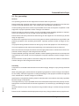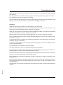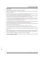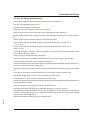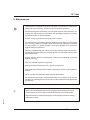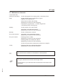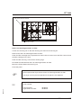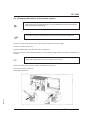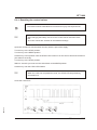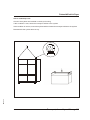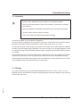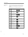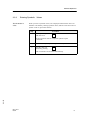
1
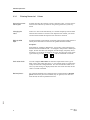
Operating Instructions
SM2-630
Dehumidified Air Dryer
STT 1600
with Siemens S7 control unit
Sterling Material Processing
Please note that our address and phone information has changed.
Please reference this page for updated contact information.
These manuals are obsolete and are provided only for their technical information, data and capacities.
Portions of these manuals detailing procedures or precautions in the operation, inspection, maintenance
and repair of the products may be inadequate, inaccurate, and/or incomplete and shouldn’t be relied
upon. Please contact the ACS Group for more current information about these manuals and their
warnings and precautions.
Parts and Service Department
The ACS Customer Service Group will provide your company with genuine OEM quality parts manufactured to engineering
design specifications, which will maximize your equipment’s performance and efficiency. To assist in expediting your phone
or fax order, please have the model and serial number of your unit when you contact us. A customer replacement parts list
is included in this manual for your convenience. ACS welcomes inquiries on all your parts needs and is dedicated to
providing excellent customer service.
For immediate assistance, please contact:
•
North, Central and South America, 8am – 5pm CST +1 (800) 483-3919 for drying, conveying, heating and cooling
and automation. For size reduction: +1 (800) 229-2919.
North America, emergencies after 5pm CST (847) 439-5855
North America email: [email protected]
•
Mexico, Central & South America
Email: [email protected]
•
Europe, Middle East & Africa +48 22 390 9720
Email: [email protected]
•
India +91 21 35329112
Email: [email protected]
•
Asia/Australia +86 512 8717 1919
Email: [email protected]
Sales and Contracting Department
Our products are sold by a worldwide network of independent sales representatives. Contact our Sales Department for the
name of the sales representative nearest you.
Let us install your system. The Contract Department offers any or all of these services: project planning; system packages
including drawings; equipment, labor, and construction materials; and union or non-union installations.
For assistance with your sales or system contracting needs please Call:
North, Central and South America +1 (262) 641-8600 or +1 (847) 273-7700 Monday–Friday, 8am–5pm CST
Europe/Middle East/Africa +48 22 390 9720
India +91 21 35329112
Asia/Australia +86 512 8717 1919
Facilities:
ACS offers facilities around the world to service you no matter where you are located. For more information, please visit us at
www.acscorporate.com
United States:
ACS Schaumburg – Corporate Offices
1100 E. Woodfield Road
Suite 588
Schaumburg, IL 60173
Phone: + 1 847 273 7700
Fax: + 1 847 273 7804
ACS New Berlin – Manufacturing Facility
th
2900 S. 160 Street
New Berlin, WI 53151
Phone : +1 262 641 8600
Fax: + 1 262 641 8653
Asia/Australia:
ACS Suzhou
109 Xingpu Road SIP
Suzhou, China 215126
Phone: + 86 8717 1919
Fax: +86 512 8717 1916
Europe/Middle East/Africa:
ACS Warsaw
Ul. Działkowa 115
02-234 Warszawa
Phone: + 48 22 390 9720
Fax: +48 22 390 9724
India
ACS India
Gat No. 191/1, Sandbhor Complex
Mhalunge, Chakan, Tal Khed,
Dist. Pune 410501, India
Phone: +91 21 35329112
Fax: + 91 20 40147576
STT 1600
Sterling Material Processing
5200 West Clinton Ave.
Milwaukee, WI 53223
Telephone: (414) 354-0970
Fax: (414) 354-6421
www.sterlco.com
Technical service:
Service department
Telephone: (800) 423-3183
Edition: 11/02
Order confirmation number: _ _ _ _ _ _ _ _ _ _ _
These operating instructions are for:*
(* Please fill in personally)
Serial number:
Built in:
Date of delivery:
Number of delivery:
Date of commissioning:
SM2-630
Location:
Group of machines:
2
STT 1600
Sterling Material Processing retains all rights to change the information in these
operating instructions at any time without notice.
SM2-630
We assume no liability for any errors or direct or indirect damage resulting in context with these operating instructions.
Copying, translation or publication in any form except for personal use of purchaser requires approval from Sterling Material Processing.
All rights reserved.
3
STT 1600
TABLE OF CONTENTS
1. General Information . . . . . . . . . . . . . . . . . . . . . . . . . . . . . . . . . . . . . . . . . . . . . . . 1-1
1.1.
1.2.
1.3.
1.4.
1.5.
Warnings and symbols . . . . . . . . . . . . . . . . . . . . . . . . . . . . . . . . . . . . . . . . . . . . . 1-2
Explanations and information . . . . . . . . . . . . . . . . . . . . . . . . . . . . . . . . . . . . . . . 1-3
Legal basis . . . . . . . . . . . . . . . . . . . . . . . . . . . . . . . . . . . . . . . . . . . . . . . . . . . . . . 1-3
Fields of applications . . . . . . . . . . . . . . . . . . . . . . . . . . . . . . . . . . . . . . . . . . . . . . 1-3
Notes on Usage . . . . . . . . . . . . . . . . . . . . . . . . . . . . . . . . . . . . . . . . . . . . . . . . . . 1-3
2. Safety instructions . . . . . . . . . . . . . . . . . . . . . . . . . . . . . . . . . . . . . . . . . . . . . . . . 2-1
2.1. For your safety . . . . . . . . . . . . . . . . . . . . . . . . . . . . . . . . . . . . . . . . . . . . . . . . . . . 2-2
2.2. For the safety of the devices . . . . . . . . . . . . . . . . . . . . . . . . . . . . . . . . . . . . . . . . 2-5
3. Start-up . . . . . . . . . . . . . . . . . . . . . . . . . . . . . . . . . . . . . . . . . . . . . . . . . . . . . . . . . . 3-1
3.1. Control system . . . . . . . . . . . . . . . . . . . . . . . . . . . . . . . . . . . . . . . . . . . . . . . . . . . 3-2
3.1.1. Key assignment . . . . . . . . . . . . . . . . . . . . . . . . . . . . . . . . . . . . . . . . . 3-2
3.1.2. Flow chart . . . . . . . . . . . . . . . . . . . . . . . . . . . . . . . . . . . . . . . . . . . . . . 3-3
3.2. Switching on the dryer . . . . . . . . . . . . . . . . . . . . . . . . . . . . . . . . . . . . . . . . . . . . . 3-4
3.2.1. Operation statuses. . . . . . . . . . . . . . . . . . . . . . . . . . . . . . . . . . . . . . . 3-4
3.3. Viewing the software-version. . . . . . . . . . . . . . . . . . . . . . . . . . . . . . . . . . . . . . . . 3-5
3.4. Passwords. . . . . . . . . . . . . . . . . . . . . . . . . . . . . . . . . . . . . . . . . . . . . . . . . . . . . . . 3-5
3.5. Basic parameters . . . . . . . . . . . . . . . . . . . . . . . . . . . . . . . . . . . . . . . . . . . . . . . . . 3-7
3.5.1. Turning the devices on/off . . . . . . . . . . . . . . . . . . . . . . . . . . . . . . . . . 3-7
3.5.2. Entering dryer values. . . . . . . . . . . . . . . . . . . . . . . . . . . . . . . . . . . . . 3-9
3.5.3. Entering hopper values . . . . . . . . . . . . . . . . . . . . . . . . . . . . . . . . . . 3-11
3.5.4. Observing processing status. . . . . . . . . . . . . . . . . . . . . . . . . . . . . . 3-13
3.5.5. Setting date and time. . . . . . . . . . . . . . . . . . . . . . . . . . . . . . . . . . . . 3-14
3.5.6. Viewing/changing language and contrast . . . . . . . . . . . . . . . . . . . 3-15
3.5.7. Changing parameters . . . . . . . . . . . . . . . . . . . . . . . . . . . . . . . . . . . 3-16
3.5.8. Setting the timer . . . . . . . . . . . . . . . . . . . . . . . . . . . . . . . . . . . . . . . . 3-17
3.6. Starting continuous operation . . . . . . . . . . . . . . . . . . . . . . . . . . . . . . . . . . . . . . 3-18
3.7. Viewing system runtime . . . . . . . . . . . . . . . . . . . . . . . . . . . . . . . . . . . . . . . . . . . 3-19
3.8. Switching the dryer off . . . . . . . . . . . . . . . . . . . . . . . . . . . . . . . . . . . . . . . . . . . . 3-20
SM2-630
4. Error and error correction . . . . . . . . . . . . . . . . . . . . . . . . . . . . . . . . . . . . . . . . . . 4-1
4
STT 1600
5. Maintenance . . . . . . . . . . . . . . . . . . . . . . . . . . . . . . . . . . . . . . . . . . . . . . . . . . . . . 5-1
5.1.
5.2.
5.3.
5.4.
5.5.
5.6.
Maintenance intervals . . . . . . . . . . . . . . . . . . . . . . . . . . . . . . . . . . . . . . . . . . . . . 5-3
Cleaning/renewing the air filters . . . . . . . . . . . . . . . . . . . . . . . . . . . . . . . . . . . . . 5-4
Tensioning the V-belts . . . . . . . . . . . . . . . . . . . . . . . . . . . . . . . . . . . . . . . . . . . . . 5-7
Disposing of the drying agent . . . . . . . . . . . . . . . . . . . . . . . . . . . . . . . . . . . . . . 5-10
Servicing the accessories . . . . . . . . . . . . . . . . . . . . . . . . . . . . . . . . . . . . . . . . . 5-10
Changing the battery of the control system . . . . . . . . . . . . . . . . . . . . . . . . . . . 5-11
5.6.1. Resetting the control values . . . . . . . . . . . . . . . . . . . . . . . . . . . . . . 5-13
6. Functional description . . . . . . . . . . . . . . . . . . . . . . . . . . . . . . . . . . . . . . . . . . . . . 6-1
6.1.
6.2.
6.3.
6.4.
6.5.
6.6.
Dryer . . . . . . . . . . . . . . . . . . . . . . . . . . . . . . . . . . . . . . . . . . . . . . . . . . . . . . . . . . . 6-2
Drying hopper (optional) . . . . . . . . . . . . . . . . . . . . . . . . . . . . . . . . . . . . . . . . . . . 6-3
Return air cooler (optional) . . . . . . . . . . . . . . . . . . . . . . . . . . . . . . . . . . . . . . . . . 6-4
Hopper heaters (optional) . . . . . . . . . . . . . . . . . . . . . . . . . . . . . . . . . . . . . . . . . . 6-5
Automatic motor flaps (optional) . . . . . . . . . . . . . . . . . . . . . . . . . . . . . . . . . . . . . 6-5
Connection to a pneumatic conveying system (optional) . . . . . . . . . . . . . . . . . 6-5
7. Transport, Assembly and Storage . . . . . . . . . . . . . . . . . . . . . . . . . . . . . . . . . . . 7-1
7.1. Transport and Packing . . . . . . . . . . . . . . . . . . . . . . . . . . . . . . . . . . . . . . . . . . . . . 7-2
7.2. Assembly . . . . . . . . . . . . . . . . . . . . . . . . . . . . . . . . . . . . . . . . . . . . . . . . . . . . . . . . 7-4
7.3. Storage . . . . . . . . . . . . . . . . . . . . . . . . . . . . . . . . . . . . . . . . . . . . . . . . . . . . . . . . . 7-4
8. Assembly instructions . . . . . . . . . . . . . . . . . . . . . . . . . . . . . . . . . . . . . . . . . . . . . 8-1
8.1.
8.2.
8.3.
8.4.
Mounting of the suction device for regeneration exhaust air . . . . . . . . . . . . . . 8-2
Filling up the drying cells . . . . . . . . . . . . . . . . . . . . . . . . . . . . . . . . . . . . . . . . . . . 8-3
Connection of the air coolers (optional) . . . . . . . . . . . . . . . . . . . . . . . . . . . . . . . 8-4
Electrical connection . . . . . . . . . . . . . . . . . . . . . . . . . . . . . . . . . . . . . . . . . . . . . . 8-5
SM2-630
9. Technical Data . . . . . . . . . . . . . . . . . . . . . . . . . . . . . . . . . . . . . . . . . . . . . . . . . . . . 9-1
5
STT 1600
10. Spare parts list . . . . . . . . . . . . . . . . . . . . . . . . . . . . . . . . . . . . . . . . . . . . . . . . . 10-1
10.1. Switching Cabinet and Operating Unit . . . . . . . . . . . . . . . . . . . . . . . . . . . . . . 10-5
11. Electrical manual . . . . . . . . . . . . . . . . . . . . . . . . . . . . . . . . . . . . . . . . . . . . . . . 11-1
o Connection diagram no.: _ _ _ _ _ _ _ _ _ _ _ _ _ _ _ _
o Currently not available; will be delivered at a later date!
12. Accessories . . . . . . . . . . . . . . . . . . . . . . . . . . . . . . . . . . . . . . . . . . . . . . . . . . . . 12-1
o Entering values on the OP 7 / 17
o Flap control with Fuzzy-Logic
o Elektror High-pressure blower with frequency converter operation
o Elektror High-pressure blower
o _____________________________
SM2-630
o _____________________________
6
Dehumidified Air Dryer
1. General Information
These operating instructions must be used by every person charged with
work on the unit.
SM2-630
»
These operating instructions are addressed to all users of the device.
General Information 1-1
Dehumidified Air Dryer
1.1. Warnings and symbols
The following warnings and symbols are used in these operating instructions:
»
This symbol indicates danger to life! Fatal or serious injury is possible if the
corresponding instructions, regulations or warnings are not observed.
This symbol indicates that serious injury is possible if the corresponding
instructions, regulations or warnings are not observed.
F
This symbol indicates that extensive damage to equipment is possible if
the corresponding instructions, regulations or warnings are not observed.
&
This symbol indicates information important for becoming familiar with
the equipment, i.e. technical correlations.
$
This symbol indicates that a technical term is explained at this point.
SM2-630
L
General Information 1-2
Dehumidified Air Dryer
1.2. Explanations and information
Various terms and designations are used in these operating instructions to ensure clarity. Therefore please note that the terms used in the text stand for the corresponding explanations listed below.
•
Equipment
”Equipment” can mean an individual unit, a machine or an installation.
•
Operating personnel
The ”operating personnel” are persons operating the equipment on their own responsibility or according to instructions.
•
Operator
The ”operator” of the equipment (production manager, foreman, etc.) is the person responsible for
all production sequences. The operator instructs the operating personnel of what is to be done.
•
Operating instructions
The ”operating instructions” describe the interaction of the equipment, production sequences or
methods. The operating instructions must be compiled by the operator of the equipment.
•
Equipment foreman
When several operating personnel work on one machine, the ”equipment foreman” coordinates
the sequences. The equipment foreman must be appointed by the operator.
•
Trained personnel
”Trained personnel” are persons who, due to their training, are authorized to carry out the required
work.
1.3. Legal basis
See “Manufacturer’s Certificate” resp. “Certificate of Conformity”.
1.4. Fields of applications
For the drying of thermoplastic granules and regrind before processing in order to remove all remaining moisture from the granules both inside and out, independent of climate or ambient air
conditions.
SM2-630
1.5. Notes on Usage
•
Experienced operators can begin directly with the chapter on “Start-up” if the unit has been properly installed.
•
If the unit has not been installed yet, observe the instructions in the chapter on “Assembly Instructions” and “Transport, Assembly and Storage”.
General Information 1-3
Dehumidified Air Dryer
2. Safety instructions
»
These safety instructions apply to all persons within the range of action of the
equipment.
Please inform all persons within the range of action of the equipment of the
direct and indirect hazards connected with the equipment.
These operating instructions are to be used by all persons assigned activities connected with the equipment.
Knowledge of the English language is prerequisite.
SM2-630
Ensure in each case that the operating personnel are familiar with the operating instructions and the function of the equipment.
Safety instructions 2-1
Dehumidified Air Dryer
2.1. For your safety
General
The operating personnel of this equipment must be at least 16 years old.
Please read these operating instructions carefully before taking into operation for the first time.
Contact us should questions arise. This avoids injury and damage to equipment!
These operating instructions must be kept available at all times at the place of operation of the
equipment. Improper operation results in danger of accidents!
Please note that, for reasons of clarity, not all conceivable cases regarding operation or maintenance of the equipment can be covered in these operating instructions.
Please observe all safety instructions and warnings on the equipment. This avoids injury and damage to equipment!
All work on the equipment is to be carried out by persons whose qualifications are specified in the
pertaining chapters of the operating instructions. Improper operation results in danger of accidents!
The proper working clothes are to be worn during any work on the equipment. This avoids injury!
The local regulations and requirements pertaining to this equipment must be observed.
Disconnect electrical components from the mains supply before work is car ried out on these components Caution: Danger to life through electrical shock!
Compile detailed operating instructions based on these Operating instructions for the sequence
of procedures to be carried out on this equipment. Improper operation results in danger of accidents!
Observe that the control system is still under voltage even when the main switch is switched off.
Caution: Danger to life through electrical shock!
Assembly
Compare the connected loads with those of the mains supply. Danger of injury through electrical
shock!
When using lifting gear, please observe the pertaining regulations. Caution: Danger of accidents!
Do not modify, add other equipment or change the design of the equipment without the approval
of the manufacturer. Caution: Danger of accidents!
Attachments not supplied by Sterling must be manufactured in accordance with safety regulation
EN 294. Danger of accidents!
SM2-630
The equipment may only be operated when all the associated components are properly connected up and in accordance with the relevant regulations. This avoids injury and damage to equipment!
Operate the device only if all its components are grounded. Danger: accident through electrical
shock!
Please note for installation that the equipment is top-heavy. Danger exists that it may topple over!
Safety instructions 2-2
Dehumidified Air Dryer
Take care that the device is not standing on the mains cable. This will prevent danger to people
and material!
The drying cells must be filled with drying agent before setting-up the dryer (only STT 1600,
STT 2400). This will prevent damage of material!
Check 5 hours after first putting into operation that the drying cells are sufficiently filled with drying
agent (only STT 1600, STT 2400). This will prevent damage of material!
Operation
Appoint an equipment foreman to be responsible for the equipment.
Ensure that the operating personnel are provided detailed instruction in the operation of the
equipment. Improper operation results in danger of accidents!
When the main switch is switched off for reasons pertaining to safety, it must be secured against
unauthorized activation. Caution: Danger of accidents!
Repair work may be carried out by trained personnel only. Caution: Danger of accidents!
Never operate the equipment when partially dismantled! Danger! Limbs may be caught in machinery! Electric shock!
In case of malfunction, shut down the equipment immediately. Have malfunctions corrected immediately. Danger of accidents!
The machine is intended only for the drying of granulated plastics. Any other or additional use is
contrary to specifications.
This equipment is not suitable for food processing.
The safety instructions of the connected machines must be followed.
Please note that sound levels exceeding 85 db(A) may in the long term damage your health. Use
the appropriate ear muffs. This avoids impairment of hearing!
Please note that the drying cells, drying hoppers and air pipings grow hot during use. Avoid touching any of these parts! Danger: Injury through burns!
Never operate the dryer without side panels. Danger: Limbs may be caught in machinery! Injury
through burns!
When drying plastics which emit gases dangerous for human health, take care that the regeneration exhaust air is disposed of without polluting the environment. This will prevent danger to people and material!
SM2-630
Operate the dryer only if there is at least one drying hopper operating. This will prevent damage of
material!
Safety instructions 2-3
Dehumidified Air Dryer
Maintenance
Before starting maintenance work, appoint a supervisor.
Inform the responsible personnel before maintenance work on the system is started. Caution:
Danger of accidents!
Disconnect the equipment from mains supply before starting maintenance procedures to ensure
that it cannot be switched on unintentionally. Caution: Danger of accidents!
All pipes, hoses and scre wed connections should be checked regularly for leaks and damage.
Any faults which arise should be corrected immediately. Danger of accidents!
Depressurise all compressed air piping before starting maintenance work. Danger of accidents!
The air filters should only be cleaned/replaced when the the main switch is off and the blower has
stopped. This avoids injury and damage to equipment!
Any maintenance work on the equipment should only be started when the the main switch is off
and the blower has stopped. This avoids injury and damage to equipment!
Check the v-belts of the blower only when the main switch is switched off and the blowers have
stopped. Caution: Danger of accidents!
Open drying hoppers only if they are completely empty. Danger of accidents!
Never open drying hoppers while the device is in operation. Danger: Iinjury through burns!
Open drying hoppers only if they have been cooled down sufficiently. Danger: Injury through
burns!
Before starting maintenance work wait until the drying cells, drying hoppers and air pipings have
been cooled down sufficiently. Avoid touching any of these parts! Danger: Injury through burns!
Remove any granules remaining on the ground. Danger of accidents!
SM2-630
Arrest the wheels after installation if the dryer is mounted on a movable frame. This will prevent
danger to people and material!
Safety instructions 2-4
Dehumidified Air Dryer
2.2. For the safety of the devices
Never change settings without carefully assessing the consequences.
Use only original Sterling spare parts.
Observe the maintenance instructions.
Keep a record of all maintenance works and repairs.
Please note that electronic components can be damaged by static discharge.
Before initial operation and in regular intervals, make sure that no electrical connections are loose.
Never readjust sensors without exactly knowing their functions.
Please ensure that the permitted storage temperature lies between -20 and +55 °C
(-4 to +131 °F).
Please ensure that the permitted operation temperature lies between 0 and +45 °C
(32 to +113 °F).
Check the direction of rotation of the blowers after the electrical connections have been made
(see rotational direction arrow).
Clean the drying hoppers before the first filling.
Note the instructions of the material manufacturer for the maximum drying temperature.
Note the drying instructions of the material manufacturer.
Take care that the drying hoppers are always completely filled and that the retention period is respected if continual removal is taking place.
Note that too large amounts taken from the drying hopper lead to insufficient drying of the material.
Close the air stop valves of drying hoppers which are empty or have not been used.
Note down all data which you have entered into the control system.
The password is to be entrusted to authorised personnel only.
Please note that the temperature of the dryer heating system must always be set lower than that of
the supplementary heaters.
When you dispose of drying agents, observe all official rules.
Note that drying cells are replaced or refilled by Sterling only if they are empty.
The material level may not fall below 40 % in the drying hopper, when material is continuously removed from the drying hopper, but no material is continuously fed into the drying hopper (batch
drying). Close the throttle valves.
SM2-630
Read the operating manuals of the connected devices.
Safety instructions 2-5
Dehumidified Air Dryer
Observe that the drying cells must be filled with drying agent before setting-up the dryer (only
STT 1600, STT 2400). This will prevent damage of material!
SM2-630
Check 5 hours after first putting into operation that the drying cells are sufficently filled with drying
agent (only STT 1600, STT 2400). This will prevent damage of material!
Safety instructions 2-6
STT 1600
3. Start-up
»
This chapter is directed at the operators of the equipment.
This chapter assumes general skills in dealing with drying systems and SPS
(PLC) control units.
This chapter assumes that the functional description has been read and understood.
It should be ensured in each and every case that the operators have the relevant skills.
F
Note down all set values of the control system.
Make sure that the cooling appliance is connected to the mains socket in
the electrical cabinet (if present, optional).
Make sure that any condensate penetrating from the cooling appliance
(optional) does not get inside the dryer or the control box.
If the inside temperature of the switch cabinet is above +50°C(122°F),
the dryer is switched off after 30 minutes if it is operated with a cooling appliance (optional).
SM2-630
&
Start-up 3-1
STT 1600
3.1. Control system
The control system is switched on at the main switch. The control system is operated via a
”selection window” and the keyboard of the operator panel.
The facility’s control system is factory-programmed. Nevertheless, you have to set specific
values (basic parameters) which are dependent on the processed material, for instance.
The values entered are stored in the control system and remain so, even after the unit is switched
off or in the event of a power cut. All messages are displayed in plain text.
In describing this start-up, we have assumed that the various sub-menus are selected from the
”table of contents”.
This structure of the description has been selected since, in most cases, you will only work on one
item in the ”submenu”.
If you want to work on several ”submenu” items in succession, you can select the individual items
directly by means of the arrow keys.
3.1.1. Key assignment
F1-key:
Leads to the table of contents.
ENTER-key:
Confirms the entries.
ESC-key:
Goes back one step in the menu.
ACK-key:
Activates an alarm message; to unblock the control system.
Arrow keys:
Move the cursor bar;
switch the appliances on or off in combination with the SHIFT key;
for scrolling forward or backward in a menu.
SHIFT-key:
Switches on the secondary functions of the keys,
when the SHIFT-key has been pushed, the LED “SHIFT” is on.
HELP-key:
Viewing additional texts,
when additional texts can be viewed the LED “HELP” is on.
LED “ALARM”:
flashes in case of an error;
is on if the error has been acknowledged but not yet
eliminated; is off if there are no errors
&
LED = light emitting diode
SM2-630
An additional alarm device (horn or lamp) can be connected (optional).
Start-up 3-2
STT 1600
3.1.2. Flow chart
1
2
3
4
5
6
7
8
9
10
Indicator lamp
Valve system
Drying chamber
Drying blower
Return air filter
Drying hopper
Drying heater
Regeneration heater
Regeneration blower
Regeneration air filter
Indicator lamp messages:
in process
alarm
SM2-630
Green continous light:
Red continous light:
Start-up 3-3
STT 1600
3.2. Switching on the dryer
Switch on the system by means of the main switch.
&
The control system carries through a self-test; after that, the name of the
dryer and the operation status of the unit are displayed.
F
Unblock the control system:
Keep the ACK key pressed until the LEDs of the keys K1 - K4 light up.
3.2.1. Operation statuses
The following operation statuses can be displayed:
system is off
•
system is on
•
blower runs on
•
valve block
•
regeneration will be finished in x min.
SM2-630
•
Start-up 3-4
STT 1600
3.3. Viewing the software-version
Press the “±”-key.
&
Lamp test: all LED’s must light up.
The software-version will be displayed (optional).
3.4. Passwords
The entry of a password prevents unauthorised persons from having access to the data entered
into the control system. Important data can then be entered or modified only after the password
has been entered.
If you make no entries for more than 10 minutes, the access is blocked and you have to re-enter
the password.
•
password level 6: 79 21 54
F
Tell the password only to authorised persons.
Press the ”Shift”-key and the ”K4”-key.
Press 3 x the “â” key.
SM2-630
Press the ”F3”-key.
Start-up 3-5
STT 1600
Login
Press the key “F2".
Enter the password.
Press the ENTER key.
&
If the password has been entered correctly, the corresponding password
level is displayed.
You can now enter data into the control system or modify data which have
already been entered.
Press the ESC key.
Logout
Press the key “F3".
&
Only data for which no password is necessary (= password level 0) can
now be entered into the control system or modified.
Press the “â“ key.
Edit
Press the key “F2".
&
This function is available only for password level 9.
Passwords and pass word levels can be modified or entered.
Confirm your entries by means of the ENTER key.
SM2-630
Press the ”F1"-key.
Start-up 3-6
STT 1600
3.5. Basic parameters
Press the ”F1"-key.
3.5.1. Turning the devices on/off
Select ”Main menu”.
Acknowledge with the ENTER-key.
or
Press the ”F2”-key.
Dryer on/off
”on” = turn dryer on, ”off” = turn dryer off.
Acknowledge with the ENTER-key.
Timer on/off
Press the SHIFT-key and choose with the arrow-keys the desired operation:
”internal” = operation with timer (operation at OP7, see chapter timer),
“external” = operation with timer (if present),
”off” = operation without timer.
Acknowledge with the ENTER-key.
&
The timer is only operating, when the dryer is switched on.
Press the “â” key.
&
If the unit operates with a return air cooler (optional):
Return air cooler on/off
“on” = operation with return air cooler, “off” = operation without return air cooler
Acknowledge with the ENTER-key.
SM2-630
Press the “â” key.
Start-up 3-7
STT 1600
Hopper X on/off (X = number of the drying hopper)
“on” = releasing drying hopper X, “off” = blocking drying hopper X
Acknowledge with the ENTER-key.
Hopper heater X on/off (X = number of the hopper heater)
“on” = switch on hopper heater X, “off” = switch off hopper heater X
Acknowledge with the ENTER-key.
SM2-630
Press the ”F1"-key.
Start-up 3-8
STT 1600
3.5.2. Entering dryer values
Select ”Dryer”.
Acknowledge with the ENTER-key.
or
Press the ”F3”-key.
Regeneration Heater Act.
The regenerated heat temperature will be displayed.
Used air Act.
The current temperature of the used air will be displayed.
Press the “â” key.
&
If the unit is operates with “dew point controlled changeover point with
dew point display” (optional):
Dew point max.
Enter the maximum permissible (worst allowed) dew point temperature (-35 to 28 °C).
Acknowledge with the ENTER-key.
Dew point Act.
The current dew point temperature will be displayed.
&
If there is a cable break “+0 °C” is dis played.
SM2-630
Press the “â” key.
Start-up 3-9
STT 1600
&
If the unit operates with a return air cooler (optional):
Return air cooler Target
Enter the max. permissible return air temperature (65 °C max. (149°F max). Higher temperatures
are not allowed. Acknowledge with the ENTER-key.
Return air cooler Act.
The current return air temperature will be displayed.
&
The cooling effect of the return air cooler is highly dependent on the
cooler circuit.
The lower the value chosen for the return air temperature, the better the
efficiency of the drying cells.
F
Plan the size of the coolant circuit accordingly.
SM2-630
Press the ”F1"-key.
Start-up 3-10
STT 1600
3.5.3. Entering hopper values
Select ”Hopper”.
Acknowledge with the ENTER-key.
or
Press the ”F4”-key.
Hopper entry X Target
(X = number of the drying hopper)
Enter the drying temperature for hopper flap X (when operating with supplementary heating).
Acknowledge with the ENTER-key.
Hopper entry X Act.
(X = number of the drying hopper)
The current temperature at the feed opening of hopper flap X will be displayed.
&
If there is a cable break “+0 °C” (32°F) is displayed.
F
The lowest drying temperature setting of the hopper flap must be the
same as or higher than the drying temperature.
SM2-630
Press the “â” key.
Start-up 3-11
STT 1600
&
If the unit operates with motor flaps (optional):
Granules X
target: _ % = _ °C (°F)
(X = number of the drying hopper)
Enter the material temperature at which the flap (optional) on the drying hopper X should close.
Confirm with the ENTER key.
&
This value is entered in percent of the temperature on the hopper inlet.
The material temperature calculated by the control system for closing the
flap on the drying hopper X is displayed in °C (°F).
Granules X
act.: _ °C (°F)
(X = number of the drying hopper)
The current material temperature in the drying hopper X is displayed in °C (°F) (optional, if there is
a flap).
SM2-630
Press the ”F1"-key.
Start-up 3-12
STT 1600
3.5.4. Observing processing status
Select ”Status”.
Acknowledge with the ENTER-key.
or
Press the ”K1”-key.
&
The current operation status of individual assembly parts is displayed:
e.g.: valve block moved in/moved out/error
“moved in” = The upper drying cells are within the drying circuit; the lower
ones are regenerated.
“moved out” = The upper drying cells are regenerated; the lower ones are
within the drying circuit.
“error” = An error has occurred.
Other operation statuses:
“on” = in operation,
“off” = out of operation,
“open” = opened,
“shut” = closed.
SM2-630
Press the “F1"-key.
Start-up 3-13
STT 1600
3.5.5. Setting date and time
&
This function is password protected.
Press the “K3"-key.
Enter the password if requested.
Date
Press the SHIFT key.
By means of the arrow keys, select the desired week-day.
By means of the arrow keys, select the shown date.
Press the SHIFT key.
Enter the desired date.
Press the ENTER key.
Time
Enter the desired time.
Press the ENTER key.
SM2-630
Press the ”F1”-key.
Start-up 3-14
STT 1600
3.5.6. Viewing/changing language and contrast
&
This function is password protected.
Press the “K4"-key.
Enter the password if requested.
Contrast
Press the SHIFT key.
By means of the arrow keys, select the adjustment which suits you best.
Press the ENTER key.
&
Depending on the outside temperature, the brightness of the screen may
vary.
Language
Press the SHIFT key.
By means of the arrow keys, select the desired language (if present).
Press the ENTER key.
SM2-630
Press the “F1"-key.
Start-up 3-15
STT 1600
3.5.7. Changing parameters
Select ”Parameters”.
Acknowledge with the ENTER-key.
or
Press the SHIFT-key and the ”K1”-key.
Run on time
drying blower
-- 300 sec.
Standard setting: 300 seconds, changes only after contacting Sterling Service.
Press the “â” key.
Parameters
F
The values in this menu may only be changed after contacting Sterling
Service.
SM2-630
Press the ”F1"-key.
Start-up 3-16
STT 1600
3.5.8. Setting the timer
Select ”Timer”.
Acknowledge with the ENTER-key.
or
Press the SHIFT-key and the ”F1”-key.
XX ON 00:00 OFF 00:00 (XX = day Mo-Su)
Enter for each day the switching on time and the switching off time.
Acknowledge with the ENTER-key.
&
Example:
Fr
Sa
Su
Mo
ON
ON
ON
ON
08:00
00:00
20:00
00:00
OFF
OFF
OFF
OFF
23:59
23:59
08:00
00:00
The dryer starts on Friday at 08:00 in the morning, runs through without
interruption until sunday at 08:00 and switches off. At 20:00 the dryer
starts again and switches off on Monday at 00:00.
SM2-630
Press the ”F1"-key.
Start-up 3-17
STT 1600
3.6. Starting continuous operation
When you have carried through all basic settings, you can start with continuous operation.
F
Make sure that hoppers which are not in use are separated from the
dehumidified air supply.
Make sure that the set drying temperatures are suited for the materials in
the hoppers.
After first filling, do not process the material until after the dwelling time.
If a return air cooler is installed, switch on the coolant circuit of the return
air cooler.
Make sure that the cooling appliance is connected to the mains socket (if
present, optional).
Check setting of the timer.
Select ”Main menu”.
Acknowledge with the ENTER-key.
or
Press the ”F2”-key.
Select ”Dryer on”.
SM2-630
Acknowledge with the ENTER-key.
Start-up 3-18
STT 1600
3.7. Viewing system runtime
Select ”System runtime”.
Acknowledge with the ENTER-key.
or
Press the SHIFT-key and the ”F2”-key.
System runtime
PLC
r.-blwr.
m.-blwr.
The runtime of the blowers and the PLC (SPS) is shown in hours.
SM2-630
&
#.## h
#.## h
#.## h
Start-up 3-19
STT 1600
3.8. Switching the dryer off
Select ”Main menu”.
Acknowledge with the ENTER-key.
or
Press the ”F2”-key.
Select ”Dryer off”.
Acknowledge with the ENTER-key.
L
Wait until the regeneration phase is finished and the blower has come to
a standstill.
Switch off the dryer at the main switch.
Disconnect the power supply.
SM2-630
F
Never switch off the dryer directly at the main switch.
Start-up 3-20
Dehumidified Air Dryer
4. Error and error correction
»
This chapter is directed at the operators of the equipment.
This chapter assumes general skills in dealing with drying systems and SPS
(PLC) control units.
This chapter assumes that the “start-up” description has been read and understood.
SM2-630
It should be ensured in each and every case that the operators have the relevant skills.
Error and error correction 4-1
Dehumidified Air Dryer
&
Alarm messages are displayed in plain language on the screen of the operator device.
The display of alarm messages in the operator device can only be erased
by pressing the ”ACK” key. The failure is not repaired.
A failure is given by flashing of the LED “alarm”. If the alarm message is
acknowledged by pressing of the “ACK” key, but the failure is not yet
eliminated, the flashing changes to steady light.
If a cooling appliance is present: If the temperature inside the switch box
is higher than +50 °C (122°F), the lamp ”alarm - temperature inside
switch box” goes on. If the temperature is still too high after 30 minutes,
the dryer is switched off.
F
Failures must be repaired immediately.
LED “ALARM”:
flashes in case of an error;
is on if the error has been acknowledged but not yet eliminated;
is off if there are no errors
SM2-630
Press the ”K2"-key.
Error and error correction 4-2
Dehumidified Air Dryer
View
Press the ”F2"-key.
All alarm messages with their numbers (see Texts), date, time and the supplement ”K”, ”G”, or ”Q”
are displayed.
&
”K” = coming (a failure occured)
Pressing the “à”-key displays the alarm message in plain text.
”G” = going (the resent for the failure has gone)
”Q” = reset (the display of the alarm message in the operator
device has been erased by pressing the ”ACK”-key)
Press the ESC-key.
Print (Optional)
&
This function is password protected.
F
Make sure that a printer is connected and switched on.
Press the ”F3"-key.
The alarm messages are printed.
SM2-630
Press the “â”-key.
Error and error correction 4-3
Dehumidified Air Dryer
Number
Press the ”F2"-key.
Total messages
The number of all alarm messages is displayed.
Waiting messages
The number of current alarm messages is displayed.
Press the ESC-key.
Delete
Press the ”F3"-key.
&
This function is password protected (Sterling service).
Press the ENTER-key for deleting the messages.
Press the ESC-key.
SM2-630
Press the “â”-key.
Error and error correction 4-4
Dehumidified Air Dryer
Overflow
Press the ”F2"-key.
&
If there are more current alarm messages than can be saved, a warning
message (= residual buffer reached) may be given.
This function is password protected (Sterling service).
Overflow warning On/Off
Press the SHIFT-key.
By means of the arrow keys, select ”on” if a warning message is to be given.
By means of the arrow keys, select ”off” if no warning message is to be given.
Press the ENTER-key.
F
If the overflow warning message is given, press the ACK-key. Delete the
alarm messages.
SM2-630
Press the ESC-key.
Error and error correction 4-5
Dehumidified Air Dryer
Text
Press the ”F3"-key.
All possible alarm messages are displayed with their numbers (see Viewing).
For viewing the possible alarm messages, press the arrow keys:
PLC (= SPS) Battery is Empty
Replace the SPS battery.
Main Switch is Off
The main switch has been placed in the off position.
The safety temperature limiter of the drying or the regeneration heater, respectively, has been activated.
The safety temperature limiter of a hopper heater has been activated.
Error valve block.
Check the safety temperature limiter.
Check the position of the valve block.
A Safety Temperature Limiter has been Activated
Check the safety temperature limiter of the drying, regeneration, or hopper heater, respectively.
Filter Door is Open
The side panels to the air filters are open.
Assemble side panels.
The Safety Switch Regeneration Blower Has Been Actuated
Check the blower.
Check the fuses.
Short circuit check of the blower.
Vacuum Regeneration Blower
The regeneration blower does not produce sufficient pressure.
Check the blower.
Vacuum sensor defective.
SM2-630
The Safety Switch Drying Blower Has Been Actuated
Check the blower.
Check the fuses.
Short circuit check of the blower.
Vacuum Drying Blower
The drying blower does not produce sufficient pressure.
Error and error correction 4-6
Dehumidified Air Dryer
Check the blower.
Vacuum sensor defective.
Temperature Measurement Regeneration Heater Defective
Check the cables and the sensor.
Check the power supply.
Short circuit check.
Excess Temperature Regeneration Heater
The regeneration temperature is too high.
Check the safety temperature limiter.
Sterling Service.
Insufficient Temperature Regeneration Heater
The regeneration temperature is too low.
Check the regeneration heater.
The Safety Switch Regeneration Heater Has Been Actuated
Check the heater.
Check the fuses.
Short circuit check of the heater.
Error Bypass Flap
The bypass flap does not close or closes too slowly.
Check the bypass flap.
Error Valve Block
The valve block has not reached the proper position. The main switch is placed in the off position.
Check the position of the valve block. Press the “ACK” key and put the main switch in the on position immediately. If the valve block has not reached the correct position within 1 minute, the main
switch is again placed in the off position.
Sterling Service.
Temperature Measurement Outgoing Air Defective
Check cables and sensor.
SM2-630
Temperature Measurement Return Air Defective
Check cables and sensor.
Excess Temperature Return Air
Check cables and sensor.
Check the return air cooler.
Error and error correction 4-7
Dehumidified Air Dryer
Temperature Measurement Drying Heater Defective
Check cables and sensor.
Check the power supply.
Short circuit check.
Excess Temperature Drying Heater
The drying temperature is too high.
Check the safety temperature limiter.
Sterling Service.
Insufficient Temperature Drying Heater
The drying temperature is too low.
Check the drying heater.
Safety Switch Drying Heater
Check the heater.
Check the fuses.
Short circuit check of the heater.
Temperature Measurement Heater Defective Hopper X
(X = number of the drying hopper)
Check cables and sensor.
Check the power supply.
Short circuit check.
Excess Temperature Heater Hopper X
(X = number of the drying hopper)
The temperature of the hopper heater is too high.
Check the safety temperature limiter.
Sterling Service.
Insufficient Temperature Heater Hopper X
(X = number of the drying hopper)
The temperature of the hopper heater is too low.
Check the hopper heater.
SM2-630
Safety Switch Heater Hopper X
(X = number of the drying hopper)
Check the heater.
Check the fuses.
Short circuit check of the heater.
Error and error correction 4-8
Dehumidified Air Dryer
Temperature Measurement Granules Defective Hopper X
(X = number of the drying hopper)
Check cables and sensor.
Check the power supply.
Short circuit check.
Excess Temperature Granules Hopper X
(X = number of the drying hopper)
The material temperature is too high.
Check the heater.
Check the throttle valve.
Valve Error Hopper X
(X = number of the drying hopper)
The throttle valve does not close or closes too slowly.
Check the throttle valve.
SM2-630
Press the “F1"-key.
Error and error correction 4-9
STT 1600
5. Maintenance
»
This chapter is intended for persons with skills in electrical and mechanical
areas due to their training, experience and received instructions.
Personnel using the instructions in this chapter must be instructed of the regulations for the prevention of accidents, the operating conditions and safety
regulations and their implementation.
Ensure in each case that the personnel are informed.
For maintenance work taking place at heights of over approx. 6 feet (1829
mm), use only ladders or similar equipment and working platforms intended
for this purpose. At greater heights, the proper equipment for protection
against falling must be worn.
Use only suitable lifting gear which is in proper working order and load suspension devices with sufficient carrying capacity. Do not stand or work under
suspended loads!
Ensure that the electric motors/switch cabinets are sufficiently protected
against moisture.
Use only suitable workshop equipment.
Before starting maintenance work, appoint a supervisor.
Inform the responsible personnel before maintenance work on the system is
started.
Never operate the equipment when partially dismantled.
All maintenace and repair work not described in this chapter, may only be
carried out by Sterling service personnel or authorized personnel (appointed
by Sterling).
L
Disconnect the equipment from mains supply before starting maintenance procedures to ensure that it cannot be switched on unintentionally.
SM2-630
Depressurize all compressed air piping of the equipment before starting
maintenance work.
Maintenance 5-1
STT 1600
F
Please observe the maintenance schedule.
Before starting maintenance work, clean the equipment of oil, fuel or lubricants.
Ensure that materials and incidentals required for operation as well as
spare parts are disposed of properly and in an environmentally sound
manner.
Use only original Sterling spare parts.
SM2-630
Keep record of all maintenance and repair procedures.
Maintenance 5-2
STT 1600
5.1. Maintenance intervals
5 hours after first
putting into operation:
Daily:
Check drying agent in the drying cells, if necessary fil upl
Check warning signs on equipment for good
legibility and completeness
Clean return air filter and housing
(depending on amount of dust collected)
Lamp test: if you press the ”+/-”-button longer than
2 seconds all LED’s must light up
Weekly:
Check function of the main switch
Clean filter of the electrical cabinet
(depending on amount of dust collected)
Monthly:
Check V-belt tension of blower
Every three months:
Clean filter of the regeneration blower
(depending on amount of dust collected)
Every six months:
Exchange return air filter
(depending on amount of dust collected)
Exchange filter of the electrical cabinet
(depending on amount of dust collected)
Check all electrical and mechanical connections for tight fit.
Yearly:
Exchange filter of the regeneration blower
(depending on amount of dust collected
&
This maintenance schedule is calculated for 3-shift operation.
F
The given maintenance intervals are average values.
SM2-630
Check whether in your individual case the maintenance intervals must be
shortened.
Maintenance 5-3
STT 1600
5.2. Cleaning/renewing the air filters
Press the ”F2”-key.
Select ”Dryer off”.
Acknowledge with the ENTER-key.
L
Wait until the blowers have stopped turning.
Switch off the dryer at the main switch.
Disconnect the power supply.
&
Clogged filters reduce the volume of circulating air to a substantial degree and result in decreased dryer efficiency. In addition, the heating elements may be damaged due to clogged filters.
SM2-630
F
Open the upper panel by means of the provided switch cabinet key.
Maintenance 5-4
STT 1600
Filter of the electrical cabinet
Return air filter
Regeneration air filter
STT 1600
Return air filter/Regeneration air filter
Loosen the securing nut on the filter housing and remove the housing lid.
Remove the return air filter/regeneration air filter.
Clean the filter cartridge with compressed air from inside to out or renew the filter. Never knock
the filter cartridge on the floor.
Clean the filter housing. Use lint-free cleaning rags.
Re-install the cleaned/new return air filter/regeneration air filter.
Mount the lid and fasten the securing nut.
Close the panel.
F
Never operate the dryer without return air filter/regeneration air filter.
&
Order number
The dryer can’t be put into operation if the panel is not replaced.
ID 86036
ID 88226
SM2-630
return air filter:
regeneration air filter:
Maintenance 5-5
STT 1600
Filter of the electrical cabinet
Remove the lid of the filter.
Remove the filter mat.
Blow through the filter mat with compressed air from inside to outside or renew the filter mat.
Clean the filter housing. Use lint-free cleaning rags.
Re-install the cleaned/new filter mat.
Replace the lid of the filter.
F
Never operate the dryer without filter mat.
&
Order number filter mat:
SM2-630
ID 87491
Maintenance 5-6
STT 1600
5.3. Tensioning the V-belts
Press the ”F2”-key.
Select ”Dryer off”.
Acknowledge with the ENTER-key.
L
Wait until the blowers have stopped turning.
Switch off the dryer at the main switch.
Disconnect the power supply.
F
Open the upper panel by means of the provided switch cabinet key.
&
Order number V-belts
”regeneration” blower:
”drying” blower:
SM2-630
”regeneration” blower
ID 94211
ID 83963
”drying” blower
STT 1600
Maintenance 5-7
STT 1600
”Regeneration” Blower
Remove the protective grid of the blower (pos. 3).
Loosen the nut (pos. 1).
Loosen and remove the screw (pos. 2).
Slide motor with carrier flange plate (pos. 6) towards the carrier flange housing (pos. 4).
Replacement: Remove defective V-belts (pos. 5), put on new ones.
Re-tensioning: Adjust belt tension by means of screw (pos. 2) in accordance with the information
plate.
Tighten the nuts on threaded bolt (pos. 1) again.
Mount the protective grid of the blower (pos. 2).
Mount the side panels.
SM2-630
F
Attention should be given to exact alignment of the V-belt pulleys.
Maintenance 5-8
STT 1600
”Drying” Blower
Remove the protective grid of the blower (pos. 7).
Loosen the nut (pos. 10).
Loosen the screw (pos. 11).
Replacement: Remove defective V-belts (pos. 32), put on new ones.
Re-tensioning: Adjust belt tension by means of screw (pos. 11) in accordance with the information plate.
Tighten the nut (pos. 10) again.
Mount the protective grid of the blower (pos. 7).
Mount the side panels.
SM2-630
F
Attention should be given to exact alignment of the V-belt pulleys.
Maintenance 5-9
STT 1600
High-pressure blowers with frequency converter operation
F
Blowers work without V-belts!
5.4. Disposing of the drying agent
Ensure that drying cells are exchanged by Sterling or refilled only when empty.
Dessicant must be disposed of in accordance with all official regulations.
Used dessicant are to be disposed of as hazardous waste, as it may be
contaminated with foreign substances from the materials dried in the
system.
F
Used dessicant drying beds cells containing useddessicant cannot be
returned to Sterling.
5.5. Servicing the accessories
SM2-630
F
The operating instructions must be followed.
Maintenance 5-10
STT 1600
5.6. Changing the battery of the control system
»
F
This work may be carried through only by qualified personnel trained in the
field of electrical engineering.
The battery may be changed only with the control system switched on.
Open the control box by means of the control box key which is part of the supply.
Open the front door of the CPU.
Pull the backup battery with cable out of the compartment.
Plug the connector of the new backup battery into the corresponding socket in the battery compart ment of
the CPU.
&
The notch on the battery connector must point to the left!
Place the backup battery into the battery compartment on the CPU.
Close the front door of the CPU
SM2-630
Close the control box.
Maintenance 5-11
STT 1600
L
Store backup batteries in a dry and cool place.
Backup batteries can be stored for approx. 5 years.
If backup batteries are not treated properly, they can ignite, explode and
cause severe burning.
&
Order number battery:
ID 83809
SM2-630
Batteries must be disposed of in keeping with the relevant national environment protection regulations/guidelines.
Maintenance 5-12
STT 1600
5.6.1. Resetting the control values
»
&
This electrical work is intended to be carried out only by trained personnel.
After changing the battery or the PLC the control values should be resetted.
All control values are set back to the standard settings.
Open the control box with the switch box key which is part of the supply.
Turn the key to the STOP position.
Turn the key to the MRES position.
Hold the key in this position until the STOP-LED comes on for the second time and remains on
(this takes 3 seconds).
Turn the key to the STOP position.
Within 3 seconds you must turn the switch back to the MRES position.
Hold the key until the STOP-LED flashes.
&
When the CPU has completed the reset, the STOP-LED stops flashing
and remains lit.
SM2-630
Close the control box.
Maintenance 5-13
STT 1600
6. Functional description
This functional description is intended for all operating personnel of the
equipment.
Prerequisite for this functional description is general knowledge of dryers
and SPS (PLC) systems.
SM2-630
Ensure in each case that the operating personnel are sufficiently informed.
Functional description 6-1
STT 1600
6.1. Dryer
The dryer operates with dehumidified air, i.e. the air is not only heated but also dehumidified
before flowing into the drying hopper. This principle allows plastic granules to be dried to a residual moisture content as low as 0.002 % (PET granulate).
The dryer operates continuously, i.e. dehumidified and, if necessary, heated air is produced continuously.
F
The dryer is designed for continuous operation.
The dryer operates with 4 drying cells; two of these cells are al ways in the drying cycle while the
others are being regenerated (change-over after 3 hours).
If a malfunction occurs in the drying cycle during the program run, regeneration is not interrupted,
but continues until the program end has been rea ched. This guarantees that 2 regenerated drying cells are always available.
The air inside the switch cabinet is cooled by a cooling appliance for the protection of temperature-sensitive components (if present, optional).
With the digital timer the dryer can be switched on and off at set times.
Dew point dependent regeneration switch (optional)
SM2-630
The dew point temperature is monitored continuously. The valve system switches to the freshly
regenerated drying cells only after the selected dew point temperature has been reached. The humid drying cells are then regenerated. After the cooling time the drying cells are ready for operation again. The valve system switches to the freshly regenerated drying cells only after the moisture content of the drying cells which are in the drying cycle have reached the setpoint value.
Functional description 6-2
STT 1600
6.2. Drying hopper (optional)
The material is dried in the drying hopper. The dehumidified air is forced through the material in
the hopper, collecting moisture in the process. The drying hopper must be dimensioned according to its intended use to ensure that the final moisture content is attained. When the hopper is filled for the first time or at the start of a drying procedure, the material in the hopper must be dried
completely before material can be removed from the hopper for the first time.
When material is continuously removed from the hopper, material must also be continuously fed
into the drying hopper. The new (moist) material is fed into the drying hopper from the top and
slowly moves downward toward the material suction box. As the material moves upward, it is
dried until its final moisture content is attained.
To ensure proper continuous drying, we recommend that the drying hopper always is kept completely filled. Automatic conveyors, such as the models included in our delivery program, optimize
the automation of the material flow.
SM2-630
F
When material is continuously removed from the hopper, but no material
is continuously fed into the drying hopper (batch drying), the material level may not fall below 40 %.
Close the throttle valves.
Functional description 6-3
STT 1600
6.3. Return air cooler (optional)
F
A return air cooler is generally required in cases in which the return air
temperature is over 65 °C(149°F).
A return air cooler improves the efficiency of the drying cells.
The return air cooler reduces the return air temperature to a defined value.
The return air temperature is set at the operation panel.
&
The lower the value chosen for the return air temperature, the better the
efficiency of the drying cells.
The dryer is automatically switched off if temperature exceeds 80 °C
(176°F).
Return air temperature is continuously monitored; the return air cooler is activated only when needed. If the return air temperature exceeds the set value (e.g. due to interruption in the cooling water supply or soiling), an alarm message is given.
SM2-630
The return air cooler can be connected to a coolant circuit or to the water mains network.
Functional description 6-4
STT 1600
6.4. Hopper heaters (optional)
If differing drying temperatures are required in the different drying hoppers, hopper heaters must
be installed on the drying hoppers. The drying temperature of each drying hopper can be set centrally at the dryer.
6.5. Automatic motor flaps (optional)
Automatic motor flaps cut off the drying hopper from the drying circuit as soon as the material is
completely dried. The supplementary heating system is also switched off. Dehumidified air flows
into the drying hopper only after new, moist material is added to the hopper. This ensures that the
material is not damaged, and saves a considerable amount of energy.
Temperature probes at the feed opening of the drying hopper and inside the drying hopper enable
comparison of feed opening and material temperature, from which the drying degree of the material can be calculated.
If the drying hopper is to be cleaned or blocked, the motor flap can be closed via the dryer. The
supplementary heating system is then automatically switched off.
6.6. Connection to a pneumatic conveying system (optional)
The dryer operates most effectively in conjunction with a pneumatic conveying system. This combination of dryer and conveying system ensures that sufficient material is always fed into the drying hopper.
Only the amount of material required for the processing machines used is removed from the hopper. This guarantees that the final drying result remains constant.
Sterling drying hoppers are available equipped with the corresponding flange for connection of a
Sterling pneumatic conveyor directly ex works.
Suction boxes can also be delivered with the required number of suction tubes. These suction boxes were developed specially for this hopper to prevent dust and foreign particles from being aspirated into the system.
SM2-630
A device for connection to the dehumidified air supply line is also available. Please note that the
function of this combination is different from that of the conventional Sterling suction boxes.
Functional description 6-5
Dehumidified Air Dryer
7. Transport, Assembly and Storage
»
This chapter is intended for all operating personnel of the equipment.
Personnel using these instructions must be instructed in the regulations for
the prevention of accidents, the operating conditions and safety regulations
and their implementation.
Ensure in each case that the operating personnel are sufficiently informed.
Please inform all persons within the range of action of the equipment of the
direct and indirect hazards connected with the equipment.
SM2-630
Please observe all safety regulations for the operation of lifting equipment.
Transport, Assembly and Storage 7-1
Dehumidified Air Dryer
7.1. Transport and Packing
»
Please ensure adequate carrying capacity of the lifting equipment.
Note that the dryer system is top-heavy. Risc of toppling!
The equipment pass a rigorous operating test in the factory and are packed carefully to avoid
transport damage.
Please check packing on delivery for transport damage.
The inlet and discharge flanges are sealed with plugs, so that no dirt can enter during transport.
Plugs must be removed before assembly.
Packing materials should be disposed of according to environmental laws or reused.
Only use for transport of the equipment a suitable lifting device (e. g. a fork lift truck or a workshop
crane).
Fasten the transport cables to the eyelets of the control cabinets.
Transport must be shock-proofed and free from vibrations.
with a fork lift truck
Push the forks up to the dryer housing.
Check that the forks reach completely under the dryer housing.
SM2-630
Transport with a fork lift truck
Transport, Assembly and Storage 7-2
Dehumidified Air Dryer
with a workshop crane
Check if the eyelets are installed on the dryer housing.
If this condition is met, fasten the transport cables to the eyelets.
If this condition is not met, mount the eyelets and then fasten the transport cables to the eyelets.
Disassemble the eyelets after set-up.
SM2-630
Transport with a workshop crane
Transport, Assembly and Storage 7-3
Dehumidified Air Dryer
7.2. Assembly
»
Please ensure adequate carrying capacity of the lifting equipment.
Check the carrying capacity of the point of installation, particularly if installed
on a platform.
The place selected for installation should be as free of vibrations as possible.
The main switch must be freely accessible.
Ground the equipment against electrostatic charging.
A special foundation is not required for installation.
The dryer must be installed on a level surface, and may not be exposed to excessive humidity.
Maximum permissible ambient temperature of the control system is 45 °C (113°F).
To facilitate servicing, install the dryer such that it is accessible from 3 sides. Make sure that the
air filters can be changed without problems. The rear of the dryer can be placed against a wall.
To conserve energy, keep the distances between dryer, hopper and processing machine as short
as possible.
The location of the control unit should be chosen so that a clear view of the separators is guaranteed from the control unit. Thus any malfunctions which arise can be corrected more easily.
Fasten the transport cables to the eyelets of the control cabinets. During transport do not contact
or push against other components with the control panels.
7.3. Storage
The control system may only be stored at temperatures from -25 to +55°C (-13 to +131 °F).
SM2-630
Between delivery and machine commissioning the equipment should be stored in a dry, dust-free
and vibration-free room.
Transport, Assembly and Storage 7-4
STT 1600
8. Assembly instructions
»
These installation instructions are intended for persons with skills in electrical and mechanical areas due to their training, experience and received instructions.
Personnel using these installation instructions must be instructed in the regulations for the prevention of accidents, the operating conditions and safety
regulations and their implementation.
Ensure in each case that the personnel are informed.
The installation instructions provided in the corresponding operating instructions apply for all connected equipment.
Observe safety regulations with regard to lifting gear handling
All installation work must be carried out with the equipment disconnected
from electrical power and compressed air supply.
L
For installation work taking place at heights of over approx. 6 feet (1829
mm), use only ladders or similar equipment and working platforms intended for this purpose. At greater heights, the proper equipment for protection against falling must be worn.
Use only suitable lifting gear which is in proper working order and load
suspension devices with sufficient carrying capacity. Do not stand or
work under suspended loads!
Use suitable workshop equipment.
SM2-630
F
Install the equipment such that all parts are easily accessible; this facilitates maintenance and repair work.
Assembly instructions 8-1
STT 1600
8.1. Mounting of the suction device for regeneration exhaust air
When plastics are dried which produce hazardous gases, environmentally sound disposal of the
regeneration exhaust air must be provided. The throughput of the regeneration blower may not be
changed.
SM2-630
It must be taken into consideration when installing a disposal system (e.g. exhaust system) that
regeneration exhaust air is extremely humid. This may result in condensation water which must
not enter the dryer again under any circumstances.
Assembly instructions 8-2
STT 1600
8.2. Filling up the drying cells
L
At delivery the drying cells are not filled with drying agent.
F
Before filling up check that the screw connection (B) is mounted.
Remove the tension ring and the tin plate
(A).
A
Fill the drying cell with drying agent up to
the nozzle (see filling level).
Füllstand
Trocknungsmittel
Filling level
drying agent
Mount the tin plate and the tension ring (A).
B
Dry ingcell
SM2-630
F
Check 4-5 hours after first putting into operation the filling level in the
drying cells, if necessary fil up drying agentl
Assembly instructions 8-3
STT 1600
8.3. Connection of the air coolers (optional)
F
A return air cooler is generally required in cases in which the return air
temperature is over 65 °C (149°F).
The return air cooler can be connected to a coolant circuit or the water mains network.
Observe the water flow with connection to water mains network. The coolant circuit must be dimensioned acccordingly.
Remove the side panel of the dryer.
Connect the coolant intake line and coolant return line to the return air cooler.
Obeserve the flow direction of the coolant through the return air cooler.
Check the connections for leaks.
SM2-630
Mount the side panel.
Assembly instructions 8-4
STT 1600
8.4. Electrical connection
»
Observe the rules of the local electricity board.
Check that the supply voltage and the power frequency are in accordance
with the data on the name plate of the device.
The electrical connection may only be carried through or assigned by Sterling service staff or by qualified staff authorized by Sterling.
Other persons are not permitted to carry through the electrical connection.
The main switch must be freely accessible.
Ground the equipment against electrostatic charging.
L
Observe that the control system is still under voltage even when the
mains switch is switched off.
F
Regularly make sure that none of the electrical or screw connections are
loose.
Immediately after connection, check the direction of rotation of the blowers (see rotational direction arrow on the blowers).
The direction of rotation should be switched in the supply line only.
The operation voltage is 480/3/60 or 240/3/60
SM2-630
Special operation voltages are possible.
Assembly instructions 8-5
STT 1600
9. Technical Data
Basic Equipment
· Centrally monitored PLC S7 drying control system with operator panel OP 7
· Central temperature controls for all heating elements to ensure constant temperature levels
· Safety temperature limiter for all heaters
· Designed for optimal regeneration time due to constant monitoring of the moisture level in the
drying cells or desiccant beds.
· Maintenance free air valves
· Automatic alarm clock or timer
· Optical alarm indication
· Function control with flow diagram
Optional Equipment
· Dew point display
· Return air cooler for high processing temperatures
· Pre-air filter
· Special color
· Special voltage
· Printer interface
· Fuzzy Logic control for automatic air distribution
· Condensation collection chamber
· High-pressure blowers with frequency converter operation
Performance
· Maximum air drying capacity of 1600 m3/h (33.990 cu.ft./hr)
· Operates with 400 V +/-10%, 3AC, 50 Hz voltage
Special voltage possible
· 49 kW connected load + max. 66 kW hopper heatings
SM2-630
· Noise level: max. 100 dB (A) without sound absorption
· Weight approx. 2300 kg (5070.55 lbs)
Technical Data 9-1
STT 1600
SM2-630
Dimension sheet
All di mensions are in mm (in). Subject to alteration.
Technical Data 9-2
STT 1600
10. Spare parts list
Version: 64.10-0233GB05 11/02
»
Other persons are not permitted to modify or repair the equipment.
ID-numbers for units with special voltage, for ex. blowers, only on request.
SM2-630
&
This spare parts list is intended to be used only by trained personnel.
Spare parts list 10-1
STT 1600
12, 16
99716
Ball bearing
16
05190
86363
Valve stem
Spindle motor 24 V
SM2-630
12
Spare parts list 10-2
STT 1600
100
72
39
31536
Sealing
72
16517
86379
88952
Motor flap (optional)
Motor
Sealing
100
83986
Moisture sensor
86387
Sensor PT 100 (12 m) (39.37 ft.)
SM2-630
39
Spare parts list 10-3
STT 1600
33
36
5
65
4
64
61
66
S89532
94211
Blower HRD 1/5
V-belt
5
83970
31924
83963
Blower HRD 7/12
Acoustic cover
V-belt
33
31516
96196
96143
28420
85533
Drying cell
Drying agent
Tension ring
Sealing ring
Tension ring
36
86356
Filter cartridge
61
88226
Filter cartridge
64
21027
Sealing
65
07050
Sealing
66
27899
85322
85652
Heating head
Silicon cable
Safety temperature limiter
SM2-630
4
Spare parts list 10-4
STT 1600
Control
27892
Front panel with flow chart
83468
CPU 315 (S7)
83809
Battery
83811
OP 7
84156
84157
Fan
Filter
Hopper heaters
Cable set heating
95828
Tubular heating element 230 V, 3 kW
85652
Safety temperature limiter (STB)
Flaps (optional)
16522
88952
Motor flap NW150, complete
Sealing
16517
88952
Motor flap NW80, complete
Sealing
86376
Motor operator 24 V, AD/DC, 50-60 Hz
18232
88952
Air control flap
Sealing
84492
Thermometer
STT 1600
93687
93686
Fine-mesh filter with filter mat (complete)
Filter mat for fine-mesh filter
85241
Digital timer (extern, optional)
86371
Sensor Pt 100 (3 m) (9.84 ft.)
93303
Sensor PT 100 (9 m) (29.53 ft.)
SM2-630
10.1. Switching Cabinet and Operating Unit
&
Observe spare parts list in the electrical manual.
Spare parts list 10-5
Dehumidified Air Dryer
11. Electrical manual
Version: 64.10-0133GB01 10/97
»
This electrical manual is intended to be used only by Sterling service
personnel and trained personnel authorized by Sterling.
Other persons are not permitted to modify or repair the equipment.
¨ Connection diagram no.: _ _ _ _ _ _ _ _ _ _ _ _ _ _ _ _
SM2-630
¨ Currently not available; will be delivered at a later date!
Electrical manual 11-1
Dehumidified Air Dryer
12. Accessories
Version: 64.10-0134GB01 10/97
¨ Entering values on the OP 7 / 17
¨ Flap control with Fuzzy-Logic
¨ Elektror High-pressure blower with frequency converter operation
¨ Elektror High-pressure blower
¨ _____________________________
SM2-630
¨ _____________________________
Accessories 12-1
Accessories
02/01GB
Entering values on the OP 7 / 17
Sterling Material Processing
General Operation
3.3
Entering Values
General procedure
In input fields, values can be entered on the OP and transferred to the PLC.
To do this, proceed as follows:
Step
Procedure
1
Branch initially to the screen you
require and then to the corresponding screen entry.
2
Using the arrow keys, select the input field you require within the
screen entry.
3
Then enter your value. Depending on how the field has been configured, values may be input as
inputs of numerical values (refer to section 3.3.1),
inputs of alphanumeric values (refer to section 3.3.2),
inputs of symbolic values (refer to section 3.3.3).
4
Confirm your input with
You can cancel any incorrect
input by pressing
ESC
The original value is then automatically reinserted in
the field. Insert the correct value and then enter the
corrected value by pressing
5
Position the cursor in the next input field, insert the next value
etc.
You can also use the arrow keys to move the cursor to the left or
right to the previous input field to insert a different value in it.
6
ESC
02/01GB
Close the screen by pressing
OP7, OP17
09/96
1
General Operation
3.3.1
Entering Numerical Values
Input using numerical keypad
In fields that allow the operator to enter a numerical value, you enter the numerical value character by character using the keypad on the system keyboard.
Changing the
value
If there is a value in the field already, it is cleared completely from the field
when the first character is entered. Once input has been started, you cannot
exit from the field until the input has been entered or canceled.
Right-justified
input
In numerical fields, input initially is normally right-justified. Digits that have
already been entered are moved to the left (pocket-calculator format).
Exception:
Input fields for variables in KM format – for instance, when calling the PU
functions STATUS/FORCE VAR – are changed to left-justified . When input
begins, the old value does not disappear from the display completely but its
bit pattern is overwritten one character at a time. You move the cursor in this
type of field by pressing
or
with activated Shift Lock mode.
You can configure limit values for numerical input fields. In this type of
field, a limit-value check takes place, i.e. the entered values are applied only
if they lie within the configured limits. If a value outside these limits is entered, a system message is displayed and, after it has been canceled, the old
value is restored in the field.
Decimal places
If a numerical field has been configured with a certain number of decimal
places and too many have been entered, they are ignored; if too few have
been entered, the field is padded with zeroes.
09/00
Limit-value check
2
OP7, OP17
09/96
General Operation
3.3.2
Entering Alphanumeric
Values
Mixed input of
digits and letters
With the input of alphanumeric values, digits and letters are mixed.
Entering A to F
characters
A to F characters can be entered directly with activated Shift Lock mode
using numeric keys 1 to 6. If you want to enter digits again after the letters,
Shift Lock mode must be de-activated. To enter the alphanumeric string
7FEB53, for example, proceed as follows:
For the numerical components of the input, proceed as described in section
3.3.1. If, however, you wish to enter a letter at the current cursor position,
you must enable the corresponding alphanumeric font. In this instance, you
move the cursor with activated Shift Lock mode with
and
.
Step
Procedure
Press
2
Press
Shift-LED is on.
3
Press in succession
4
Press
Shift-LED goes out.
5
Press in succession
6
Confirm by pressing
7
\
6
F
5
E
5
E
3
C
2
B
\
\b
02/01GB
1
OP7, OP17
09/96
3
General Operation
Extended character set
If the characters available on the keypad are not sufficient for the alphanumeric input, you can select additional letters and special characters from the
extended character set. The extended character set is available for all KC
type fields.
To enter the string 18OKT61, for example, proceed as follows:
Step
Procedure
1
Press in succession
2
Press
Shift-LED is on.
1
A
8
\
The extended character set is available.
3
Scroll with the arrow
keys through the extended
character set.
4
Select O and, using the
arrow key, move right
one position.
The character you selected is applied by moving the cursor.
Select K and, using the
arrow key, move right
one position.
6
Select T and, using the
arrow key, move right
one position.
7
Press
Shift-LED goes out.
8
Press in succession
9
Confirm by pressing
\
6
F
1
A
\b
02/01GB
5
4
OP7, OP17
09/96
General Operation
3.3.3
Entering Symbolic Values
Text instead of a
value
When you enter a symbolic value, text is displayed instead of the value. If a
field has to be filled by entering symbolic values, take the value from a list of
options. To do so, proceed as follows:
Step
1
Procedure
In the input field press
Shift LED is on.
\
The list of options with its configured symbolic inputs
is activated.
2
Select the value you require using the arrow keys.
3
Enter the value you
selected by pressing
\b
02/01GB
Shift Lock mode is de-activated automatically.
OP7, OP17
09/96
5
Accessories
10/00GB
Flap control
with Fuzzy-Logic
Sterling Material Processing
Flap control with Fuzzy-Logic
F
Observe that the hopper is not switched off after the flap has closed.
Turning hopper off: see chapter “start-up, turning the devices on/off”.
Control unit “flap”
Switch position:
0
= “Quick closing”
flap closes quick
1 = “Slow closing”
flap closes controlled
2 = “Automatic control”
flap operates pulsed
(opening/closing)
1
2
10/00GB
0
2