1
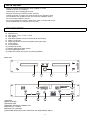
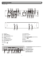
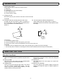
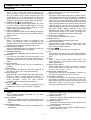
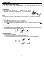
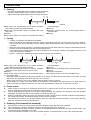
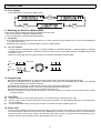
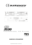
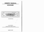
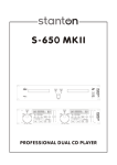
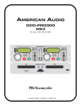
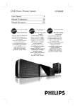
USER MANUAL REMAIN REMAIN CONTINU TRACK M S F CONTINU TRACK M S F PROFESSIONAL DUAL CD PLAYER IMPORTANT TO SAFETY •Unauthorized modification of this unit may cause it to no longer comply with FCC regulations and void your authority to use this device. Cet appareil numérique de la classe B respecte toutes les exigencies du Rèsur le materiel brouilleur du Canada. IMPORTANT TO SAFETY WARNING: TO PREVENT FIRE OR SHOCK HAZARD, DO NOT EXPOSE THIS APPLIANCE TO RAIN OR MOISTURE. CAUTION: 1. Handle the power supply cord carefully Do not damage or deform the power supply cord. If it is damaged or deformed, it may cause electric shock or malfunction when used. When removing from wall outlet, be sure to remove by holding the plug attachment and not by pulling the cord. NOTE: This CD player uses the semiconductor laser. To allow you to enjoy music at a stable operation, it is recommended to use this in a room of 5ºC 41ºF - 35ºC 95ºF. 2. In order to prevent electric shock, do not open the top cover. If a problem occurs, contact your dealer. RATING LABEL 3. Do not place metal objects or spill liquid inside the CD player. Electric shock or malfunction may result. Please, record and retain the Model name and serial number of your set shown on the rating label. Model No. ___________ Serial No. ___________ CLASS 1 LABEL CAUTION: TO REDUCE THE RISK OF ELECTRIC SHOCK, DO NOT REMOVE THE COVER (OR BACK) . THERE ARE NO SERVICEABLE PARTS INSIDE. REFER SERVICING TO QUALIFIED SERVICE PERSONNEL. CAUTION: USE OF CONTROLS OR ADJUSTMENTS OR REFORMANCE OF PROCEDURES OTHER THAN THOSE SPECIFIED HEREIN MAY RESULT IN HAZARDOUS RADIATION EXPOSURE. The lightning flash with arrowhead symbol, within an equilateral triangle, is intended to alert the user to the presence of uninsulated "dangerous voltage" within the product's enclosure that may be of sufficient magnitude to constitute a risk of electric shock to persons. THE COMPACT DISC PLAYER SHOULD NOT BE ADJUSTED OR REPAIRED BY ANYONE EXCEPT PROPERLY QUALIFIED SERVICE PERSONNEL. DOUBLE INSULATED - WHEN SERVICING, USE ONLY IDENTICAL REPLACEMENT PARTS. The exclamation point within an equilateral triangle is intended to alert the user to the presence of important operating and maintenance (servicing) instructions in the literature accompanying the appliance. NOTE: This unit may cause interference to radio and television reception. •FOR U.S.A. & CANADA MODEL ONLY *FOR DUAL VOLTAGE MODEL ONLY CAUTION TO PREVENT ELECTRIC SHOCK DO NOT USE THIS (POLARIZED) PLUG WITH AN EXTENSION CORD, RECEPTACLE OR OTHER OUTLET UNLESS THE BLADES CAN BE FULLY INSERTED TO PREVENT BLADE EXPOSURE. • Line Voltage Selection (for multiple voltage model only) The desired voltage may be set with the 115V VOLTAGE SELECTOR switch on the rear panel, using a screwdriver. Do not twist the VOLTAGE SELECTOR 230V switch with excessive force as this may cause damage. If the VOLTAGE SELECTOR switch does not move smoothly, please contact a qualified serviceman. •This device complies with Part 15 of the FCC Rules Operation is Subject to the following two conditions (1) This device may not Cause harmful interference, and (2) this device must accept any Interference received. Including interference that may cause Undesired operation. •This Class B digital apparatus meets all requirements of the Canadian Interference-Causing Equipment Regulations. 1 SAFETY INSTRUCTIONS 1. Read Instructions – All the safety and operating instructions should be read before this product is operated. 2. Retain Instructions - The safety and operating instructions should be retained for future reference. 3. Heed Warnings - All warnings on the appliance and in the operating instructions should be adhered to. 4. Follow Instructions - All operating and use instructions should be followed. 5. Water and Moisture - The appliance should not be used near water - for example, near a bathtub, washbowl, kitchen sink, laundry tub, in a wet basement, or near a swimming pool, and the like. 6. Carts and Stands - The appliance should be used only with a cart or stand that is recommended by the manufacturer. An appliance and cart combination should be moved with care. Quick stops, excessive force, and uneven surfaces may cause the appliance and cart combination to overturn. 7. Wall or Ceiling Mounting - The product should be mounted to a wall or ceiling only as recommended by the manufacturer. 8. Heat - The appliance should be situated away from heat sources such as radiators, heat registers, stoves, or other appliances (including amplifiers) that produce heat. 9. Power Sources – This product should be operated only from the type of power source indicated on the rating label. If you are not sure of the type of power supply to your home, consult your product dealer or local power company. For products intended to operate from battery power, or other sources, refer the operating instructions. 10. Grounding or Polarization – This product may be equipped with a polarized alternation-current line plug (a plug having one blade wider than the other). This plug will fit into the power outlet only one way. This is a safety feature. If you are unable to insert the plug fully into the outlet, try reversing the plug. If the plug should still fail to fit, contact your electrician to replace your obsolete outlet. Do not defeat the safety purpose of the polarized plug. 11. Power-Cord Protection-Power-supply cords should be routed so that they are not likely to be walked on or pinched by items placed upon or against them, paying particular attention to the cord in correspondence of plugs, convenience receptacles, and the point where they exit from the appliance. 12. Cleaning - The appliance should be cleaned only as recommended by the manufacturer. Clean by wiping with a cloth slightly damp with water. Avoid getting water inside the appliance. 13. For AC line powered units - Before returning repaired unit to user, use an ohm-meter to measure from both AC plug blades to all exposed metallic parts. The resistance should be more than 100,000 ohms. 14. Non-use Periods-The power cord of the appliance should be unplugged from the outlet when left unused for a long period of time. 15. Object and Liquid Entry-Care should be taken so that objects do not fall and liquids are not spilled into the enclosure through openings. 16. Damage Requiring Service-The appliance should be serviced by qualified service personnel when: A. The power-supply cord or the plug has been damaged; or B. Objects have fallen, or liquid has been spilled into the appliance; or C. The appliance has been exposed to rain; or D. The appliance does not appear to operate normally or exhibits a marked change in performance; or E. The appliance has been dropped, or the enclosure damaged. 17. Servicing-The user should not attempt any service to the appliance beyond that described in the operating instructions. All other servicing should be referred to qualified service personnel. 18. Ventilation – Slots and openings in the cabinet are provided for ventilation and to ensure reliable operation of the product and to protect it from overheating, and these openings must not be blocked or covered. The openings should never be blocked by placing the product on a bed, sofa, rug, or other similar surface. This product should not be placed in a built-in installation such as a bookcase or rack unless proper ventilation is the manufacturer’s instructions have been adhered to. 19. Attachments – do not use attachments not recommended by the product manufacturer as they may cause hazards. 20. Accessories – Do not place this product on an unstable cart, stand, tripod, bracket, or table. The product may fall, causing serious injury to a child or adult, and serious damage to the product. Use only with a cart, stand, tripod, bracket, or table recommended by the manufacturer, or sold with the product. Any mounting of the product should follow the manufacturer’s instructions, and should use a mounting accessory recommended by the manufacturer. 21. Lightning – For added protection for this product during a lightning storm, or when it is left unattended and unused for long periods of time, unplug it from the wall outlet and disconnect the antenna or cable system. This will prevent damage to the product due to lightning and power-line surges. 22. Replacement Parts – When replacement parts are required, be sure the service technician has used replacement parts specified by the manufacturer or have the same characteristics as the original part. Unauthorized substitutions may result in fire, electric shock, or other hazards. 23. Safety Check – Upon completion of any service or repairs to this product, ask the service technician to perform safety checks to determine that the product is in proper operating condition. 2 NOTE ON USE Allow for sufficient heat dispersion when installed on a rack. Handle the power cord carefully. Hold the plug when unplugging the cord. Keep the set free from moisture, water, and dust. Unplug the power cord when not using the set for long periods of time. Do not obstruct the ventilation holes. (For sets with ventilation holes.) Do not let foreign objects in the set. Do not let insecticides, benzene, and thinner come in contact with the set. Never disassemble or modify the set in any way. MAIN FEATURES 1) 2) 3) 4) 5) 6) 7) 8) 9) 10) 11) 12) 13) Auto cue function Real-time cue Pitch range: +/-8%, +/-12%, +/-16% Pitch display Selectable elapsed, remain and total remain time display Single / continuous Relay play allows consecutive playback during two decks Frame search 4 Scan Speeds Transport protection S/PDIF digital audio RCA coaxial 20 programmable tracks Fader start, Fader stop, (back cue), Relay playback. MAIN UNIT 2 3 1 2 6 4 5 7 (1)POWER (2) DISC HOLDER (3) OPEN/CLOSE (4) REMOTE CONTROL CONNECTOR (5) AUDIO OUT L AND R (6) DIGITAL OUT SOCKET (7)VOLTAGE SELECTOR (JUST FOR DUAL VOLTAGE MODEL ONLY) 3 4 5 MAIN FEATURES CONTROL UNIT 3 2 4 8 5 6 7 21 9 REMAIN REMAIN CONTINU TRACK 1 11 M S (1) (2) (3) (4) (5) (6) (7) (8) (9) (10) (11) (12) CONTINU F TRACK 12 13 15 16 18 22 10 14 M S 17 19 20 22 23 SHUTTLE OPEN/CLOSE TIME (Time Button) LCD (Liquid Crystal Display) SGL (Single Button) PROG. PROGRAM Indicator RELOOP (Reloop button) PITCH (Pitch Indicator) PITCH SLIDER JOG B.SKIP (13) (14) (15) (16) (17) (18) (19) (20) (21) (22) (23) F 23 CUE Indicator CUE (Cue Button) +10 PLAY Indicator PLAY/PAUSE / (Play/Pause Button) F.SKIP IN OUT PITCH (Pitch Button) CONTROL CONNECTOR CONTROL SOCKETS LCD (24)(26)(27)(28)TRACK,MINUTE,SECOND and FRAME Displays (25) BAR Indicators (29) ELAPSED Indicator (30) CONTINU Indicator (31) SINGLE Indicator (32) REMAIN Indicator (33) PITCH DISPLAY ELAPSED REMAIN SINGLE CONTINU TRACK 24 M 25 26 S 27 F 28 29 30 31 32 33 4 PREPARATIONS 1. Checking the Contents Check that the carton contains the following items: 1) Main unit 2) Control unit 3) Operating instructions (this booklet) 4) Pair of RCA pin cord. 5) Control cords (1 meter) 2. Installing the Unit Mount the unit onto your console or rack with 19" EIA rack rails. CAUTION: zThe player will work normally when the main unit is mounted with the front panel at within 15 degrees of the vertical plane. If the unit is tilted excessively, discs may not be loaded or unloaded properly. (Figure 1) zThe control panel's LCDs are designed to be clearly visible within the angles shown in Figure 2. Mount the control unit so that the visual angle is within this range. Max. 15° 45° 5° Control panel Button Main unit . Figure 1 Figure 2 Connections 1) Turn off the POWER switch. 2) Connect the RCA pin cord to the input on your mixer. 3) Connect the control cords to the REMOTE connector on the main unit. CAUTION: • Be sure to use the supplied control cords. Using another type of cable may result in damage. • Be sure the power is off when connecting the control cords. Otherwise the units may not work properly. NAMES AND FUNCTIONS Main Unit Front Panel (4) REMOTE CONTROL CONNECTOR Connect this connector to the control unit using the included control cord. (5) AUDIO OUT The audio signals from each player are output from these jacks. (6) DIGITAL OUT SOCKET The music-signal of this socket is digital. Connect the output to the respective input of a digital amplifier for example. (1) POWER (Power ON/OFF Switch) When the POWER switch is pressed, the power turns on. (2) DISC HOLDER Place the discs in the holder. Press the OPEN/CLOSE button to open and close the disc holder. (3) OPEN/CLOSE Press it to open and close the disc holder. The control unit also includes OPEN/CLOSE button. The disc holder cannot be opened during playback, so stop playback before pressing the button. 5 NAMES AND FUNCTIONS Control Unit (1) SHUTTLE (Shuttle Dial) Use the dial to select the scanning direction and speed. The disc is scanned in the forward direction when the shuttle dial is turned clockwise from the neutral position, in the reverse direction when the shuttle dial in turned counterclockwise. The scanning speed increases when the shuttle dial is turned faster. (2) OPEN/CLOSE (Open/Close Button) Press it to open and close the disc holder. The main unit also includes OPEN/CLOSE buttons. The disc holder cannot be opened during playback, so stop playback before pressing the button. (3) TIME (Time Button) Press this button to switch the time display among the elapsed time and remaining time and total remaining time of the disc. (4) LCD (5) SGL (Single Button) Press it to switch the single and continuous play modes. The SINGLE mode is indicated by the SINGLE indicator on the LCD and continuous mode is indicated by the CONTINU indicator on the LCD. (6) PROG (Program Button) Press the PROGRAM button, the player will enter the program mode and stop the CD playback. (7) PROGRAM Indicator The PROGRAM LED lights when program mode is set. (8) RELOOP If a Loop has been made, but the CD Player is not actively in Loop mode, press the RELOOP button to reactivate the loop mode. To exit loop, press the OUT button. (9) PITCH Indicator When the indicator lights, the pitch adjustment is enabled. (10)Pitch Slider Use the slider to adjust the CD pitch. Slide up to decrease the pitch, down to increase the pitch. (11)JOG (Jog Dial) When the dial is turned during CD pause, the point at which the sound is being produced mover by a number of frames corresponding to the number of clicks. Clockwise moves the point forward, counterclockwise moves the point backward. (12)B. SKIP Use these buttons to go back to the beginning of the current track or select a previous track for playing. (13)CUE Indicator When in CUE mode, the CUE indicator lights. (14)CUE (Cue Button) Pressing the CUE button during play provides a return to the position at which play was started. If PAUSE is used before CUE or a CUE POINT was set, that will become the cue point. Alternately pressing the Play button and the CUE button allows the CD to be played from the same position any number of times. The CUE LED will light up from the time the CUE button is pressed until the CD has reset to the position at which play was started. Steady lighting of this LED indications the ready condition. The CUE button can be held down to play a CD. When you release the CUE button it instantly returns to the CUE POINT. (15)+10 (Track +10 Button) Use the button to skip ahead 10 tracks. (16)PLAY Indicator The PLAY indicator lights during play mode. (17)PLAY/PAUSE Button Use the button to start playback. Press once to start playback, once again to set the pause mode, and once more to resume playback. (18)F. SKIP Use these buttons to skip to the next CD track. (19)IN This allows you to set the cue point without stopping the play back. This button also sets the beginning of a loop. (20)OUT Used to set the ending when looping music. The player will start to loop continues until you press this button again to exit. (21)PITCH (Pitch Button) Press PITCH button to switch on/off pitch.; hold the PITCH button down for more than 0.6 sec to switch pitch in +/-8% / +/-12% / +/-16%. (22)CONTROL CONNECTOR Connect this connector to the REMOTE connector on the main unit using the included control cord. (23)CONTROL SOCKET Via the Control socket, the respective CD-player can be remotely controlled. If you are using a mixer with fader start-function connect the player with the Control Out-socket. Please note that these sockets must never be connected with any voltage. LCD (30) CONTINU Indicator When the indicator lights, the function will cause the unit to play continuously. (31) SINGLE Indicator When the indicator lights, playback will stop at the beginning of the next track. (32) REMAIN Indicator It indicates that the time shown on the display is the remaining time of playing track. (33) PITCH DISPLAY It shows the BPM change range, the BPM changes within a range of +/-12%. (24) ~(27)TRACK, MINUTE, SECOND and FRAME Displays These displays indicate information for the CD’s current position and time. (28) BAR Indicator These ten indicators provide a visual display of the approximate position of the pickup within the current track. (29) ELAPSED Indicator It indicates that the time shown for the display is the elapsed time. 6 OPERATIONS 1. Opening and Closing the Disc Holder z Turn the unit power on. Press the OPEN/CLOSE button to open the disc holder. OPEN/CLOSE buttons are provided on both the main unit and control unit. z The disc holder cannot be opened during playback to prevent playback from being interrupted if the OPEN/CLOSE button is pressed accidentally. Stop the playback first, then press the OPEN/CLOSE button. 2. Loading discs Hold the disc by the edges and place it in the disc holder, then press the OPEN/CLOSE button again to close the disc holder. The unit will show the total track number and the total playing time for about 2 seconds then enter the cue condition, the cue point will be set to the music starting point of the first track automatically. Figure 2-1 CAUTION: z Do not place any foreign objects in the disc holder, and do not place more than one disc in the disc holder at a time. z Do not push the disc holder in manually when the power is off, as this may result in malfunction and damages the player. 3. Selecting Tracks z z z z Press the SKIP button once to move to next higher or lower track. Hold the SKIP button to change tracks continuously at a higher speed. When a new track is selected during playback, playback begins as soon as the skip search operation is completed. button is pressed while at the last track, the first track is selected. In the same way, if the skip If the skip button is pressed while at the first track, the last track is selected. 4. Starting Playback z Press the PLAY/PAUSE button during the pause or cue condition to start playback, the PLAY indicator lights. z The point at which playback starts is automatically stored in the memory as the cue point. The pickup then returns to the cue point when the CUE button is pressed. (Back Cue) Figure 4-1 5. Stopping Playback There are two ways to stop playback. 1. Press the PLAY/PAUSE button during playback to pause at that point. 2. Press the CUE button during playback to return to the cue point and enter pause condition.(Back Cue) CUE Figure 5 7 OPERATIONS 6. Pausing ˙ Press the PLAY/PAUSE button to switch the play and pause. ˙ The play indicator flashes when the pause mode is set. ˙ Figure 6 show the relationship between the play and pause. 2 4 6 3 7 1 5 Figure 6 is pressed again rPausing. sPlayback resumes when the PLAY/PAUSE button is pressed again. tPlaying. nThe player has completed the cue or pause operation and is waiting for the play start command. oWhen the PLAY/PAUSE button is pressed and enter play mode. pPlaying. qThe pause mode is set when the PLAY/PAUSE button 7. Cueing ˙ "Cueing" is the action of preparing for playback. ˙ Press CUE button, the player will enter cue mode, the playback returns to cue point and enter pause condition, the cue indicator light up and play indicator flashes. When PLAY/PAUSE button is pressed, play starts from the cue point. ˙ When the track search operation is completed after pressing the SKIP buttons, the player automatically finds the position at which the sound starts and cues there(Auto Cue). ˙ If the CUE button is pressed after the search operation or the scanning operation, the playback returns to cue point and enter pause condition. ˙ Figure 7-1 shows the relationship between the play and back cue operations. 2 8 2 3 1 9 4 6 8 3 7 1 5 9 Figure 7-1 is pressed again. nThe player has completed the cue or pause operation rPausing. and is waiting for the play start command. sWhen the PLAY/PAUSE button is pressed again; oWhen the PLAY/PAUSE button is pressed, playback tPlaying. starts and the cue point is stored in the memory. uPress the CUE button. pPlaying. vThe pickup returns to the cue point.(Back Cue) qThe pause mode is set when the PLAY/PAUSE button Cue point setting: When play starts from pause by pressing IN button or Scanning or Frame Search; also skip to a new track by using skip button, the begin play point will be set to the new cue point. When a new cue point is set, the cue indicator lights by flash for about 1 second. NOTE: Daring cue mode, if the CUE button is pressed and hold, playback will start from the cue point, when the button is released, the player will return to the cue mode automatically, it allows you to check the cue point. 8. Frame search z Frame search is a function for monitoring the sound at a certain section of the disc and manually changing the position. Searching is used to set play start points with precision. z Turn the JOG dial while in pause or cue mode to begin searching. The sound for one revolution of the disc is output repeatedly. The point at which the sound starts is indicated on the LCD. z When the JOG dial is turned, the point from which the sound is output moves a number of frames corresponding to the number of the clicks, and the time display on the LCD also changes. z The search point moves in the forward direction when the JOG dial is turned clockwise, in the reverse direction when the JOG dial is turned counterclockwise. 9. Scanning (Fast forward/Fast backward) z Scanning is a function for moving quickly forward or backward when the SHUTTLE is rotated. z This unit supports 4 different speeds according to the rotating angle of the SHUTTLE. z Turn the shuttle dial to begin scanning. The disc moves rapidly forward or backward and the sound is output. The current scan point is indicated on the LCD. z Turn the shuttle dial clockwise to scan in the forward direction, counterclockwise to scan in the reverse direction. 8 OPERATIONS 10. Time display Press TIME button to select time display mode: TIME TIME TIME 11. Matching the Beats Per Minute (BPM) There are two tools available for matching the BPM of the two CDs: c Use the pitch slider to adjust the BPM satirically. d Turn the JOG dial to change the BPM temporarily. 1) Pitch Slider n To adjust the BPM by sliding the pitch slider up or down, press the PITCH button to turn on the PITCH adjustment function before using. o Slide the pitch slider up to decrease BPM, or down to increase BPM. 2) Turn the JOG dial Turn the jog dial clockwise during play to increase the BMP in the forward direction, counterclockwise to decrease the BMP in the reverse direction. The faster you turn the wheel, the more the BMP changes. The BMP changes with a range of +/-16%. When you release jog wheel, the CD will return to the tempo indicated by the pitch slider. CD1 bass beat Bass beat CD2 bass beat Bass beat 12. Program play n Press the PROGRAM button, the player will enter the program mode and the CD will stop rotating. o Select the desired track by pressing the SKIP button, then press the PROGRAM button again. The selected track will be added to the program sequence. p Repeat step 2 operation. A maximum of 20 tracks can be programmed at one time. q Press the PLAY/PAUSE button to start the program play from the first selection. r Press the program button again during program play to stop play. s Press and hold the program button more than 2 seconds to cancel the program mode and erase all the current program contents. 13. Loop Play n Press the IN button to set the loop start point A, the LOOP indicator will flashes on the LCD. o Press the OUT button to set the loop end point B, after the B point is set, the playback will enter the loop play from A to B repeatedly. p Press the RELOOP button, the loop play function is canceled, the LOOP indicator goes out. 14. Fader start You have the possibility to start the respective CD-player directly from the mixer. Make sure that the Control socket is connected with the respective socket on the mixer. Additionally, the Audio out socket have to be connected with the Line-input sockets of your mixer. Please note that the Fader start function only works with the appropriate mixers. Insert the CD and select the desired track. Start playback from your mixer. 9 OPERATIONS 15. Relay-Play In the Relay-operation, the device automatically switches to the other player after the current track is played. In this way, you have the possibility to automate the play features between the two CDs. As soon as the current track of CD1 is finished, the player automatically starts CD2. The first CD-player goes into Pause-mode. You can enter a new CD or memorize a Cue-point at the respective player in the Pause-Mode. To initiate single relay play: Press the SGL (Single-button); The display shows “SINGLE” on both CD-players. Then press both PROG. & SGL buttons simultaneously until the track indicator blinks (on both LCDs). Start playback of CD1. In the Single-mode, the device automatically starts with the playback of the other CD-player of the other CD-player at the end of the track. This can be changed to continuous by pressing the SGL (single) button once. In continuous mode the entire CD has to play before the second player automatically starts. ***Note*** During the Relay-operation, the Faderstart function is disabled. CAUTION: The Relay-operation does not work properly if the two CD-players are connected to different power amplifiers. BEFORE SWITCHING OFF THE POWER When you have finished using the CD player, before switching off the power, be sure that the disc holder had been closed with the OPEN/CLOSE button. CAUTION: Do not forcibly close the disc holder when the power is off. POWER OFF POWER OFF 8 Do not switch off the power when the disc holder is open. Switch off the power after the disc holder has been closed with the OPEN/CLOSE button. COMPACT DISCS y Condensation will form if a disc is brought into a warm area from a colder one, such as outdoors in winter. Do not attempt to dry the disc with a hair dryer, etc. 2. Precaution on storage y After playing a disc, always unload it from the player. y Always store the disc in the jewel case protect from dirt or damage. y Do not place discs in the following areas: c Areas exposed to directs sunlight for a considerable time. d Areas subject to accumulation of dust or high humidity. e Areas affected by heat from indoor heaters, etc. 1. Precautions on handling compact discs y Do not allow fingerprints, oil or dust to get on the surface of the disc. If the disc is dirty, wipe it off with a soft dry cloth. y Do not use benzene, thinner, water, record spray, electrostatic-proof chemicals, or silicone-treated cloths to clean discs. y Always handle discs carefully to prevent damaging the surface; in particular when removing a disc from its case or returning it. y Do not bend the disc. y Do not apply heat. y Do not enlarge the hole in the center of the disc. y Do not write on the label (printed side) with a hardtipped implement such as a pencil or ball point pen. 10 SPECIFICATIONS GENERAL Dimensions: Main unit: Control unit: Weight: Power supply: Power consumption: 482(W) x 88.8(H) x 251(D) mm 19”(W) x 3 1/2”(H) x 9 4/5”(D) 482(W) x 88.8(H) x 60(D) mm 19”(W) x 3 1/2”(H) x 2 1/3(D) 5 kgs / 11 lbs 2 kgs / 4.4 lbs Player unit: Control unit: Dual Voltage: AC 115/230V, 50/60Hz Single Voltage: AC 100V, 50Hz (For Japan) AC 110V, 60Hz (For Taiwan) AC 120V, 60Hz (For U.S.A.,Canada) AC 127V, 60Hz (For Mexico) AC 220V, 50Hz (For United Arab Emirates,Chile,Aegentina) AC 220V, 60Hz (For Philippines) AC 230V, 50Hz (For Europe,U.K.,New Zealand,South Africa,Singapore,Israel) AC 240V, 50Hz (For Australia) 25W 11 Stanton Magnetics, Inc. – Warranty Provision – Returns for Repairs or Replacement WARRANTY Through Stanton’s authorized dealers around the World, Stanton, or one of Stanton’s authorized distributors outside the U.S., will, without charge, repair or replace, at the sole discretion of the entity responsible for making the repair or providing the replacement, any Stanton merchandise proved defective in material or workmanship for a period of one (1) year (three (3) years for C.D. players) following the date of original purchase. Exceptions to this warranty are as noted below: The warranty for mechanical parts which are subject to wear and tear are limited to the earlier to occur of thirty (30) days following the date of original purchase or the following number of cycles: Faders - 15,000; Rotary potentiometers - 10,000; and Switches - 10,000. Stanton will warrant all replacement parts and repairs for ninety (90) days from the date of original shipment. Repairs made necessary by reason of misuse, alteration, normal wear, or accident are not covered under this warranty. RETURNS Authorized Stanton dealers are only authorized to sell and distribute merchandise within a specific country. All goods requiring warranty repair or replacement must be returned (freight prepaid if not hand-delivered) to the authorized Stanton dealer from whom the merchandise was purchased and in the same country where the merchandise was purchased. For purposes of purchases made via the Internet, the merchandise must be returned to the authorized Stanton dealer in the country where the authorized Stanton dealer which sold the merchandise to purchaser is located and not the authorized Stanton dealer in the country where the purchaser is located or the country in which the merchandise was received. Any returns to a non-authorized dealer or to an authorized Stanton dealer not in the same country as the merchandise was intended to be sold or as set forth above will void this warranty. To initiate a warranty repair, you must contact the authorized Stanton dealer from whom you purchased the merchandise, and follow such authorized Stanton dealer’s return policy. Stanton assumes no risk and shall be subject to no liability for damages or loss resulting from the specific use or application made of the merchandise. Stanton's liability for any claim, whether based on breach of contract, negligence, infringement of any rights of any party, or product liability, and relating to the merchandise shall not exceed the price received by Stanton from your purchase of such merchandise. In no event will Stanton be liable for any special, incidental or consequential damages (including loss of use, loss of profit and claims of third parties) however caused, whether by the negligence of Stanton or otherwise. To the extent permitted by law and except as otherwise provided above, Stanton disclaims any express or implied warranties of merchantability or fitness for a particular purpose. The above warranty provides you with specific legal rights. You may also have additional rights, which are subject to variation from state to state and country to country. If there is a dispute regarding the warranty of merchandise that does not fall under the warranty conditions stated above, please include a written explanation with the merchandise when returned pursuant to the terms and conditions set forth herein. Please register your product online at www.stantondj.com or mail your completed warranty card to: Stanton Magnetics, Inc, 3000 SW 42 St. Hollywood, Florida 33312. cut along dotted line State Where did you buy this product? Date of Purchase Serial Number Model Number PRODUCT INFO Telephone Country City Address Name PERSONAL INFO Zip If you have internet access, please register your product at www.stantondj.com. Otherwise, return this card completely filled out in order to validate your warranty. STANTON WARRANTY REGISTRATION CARD PLACE STAMP HERE Stanton Magnetics, Inc. 3000 SW 42nd Street Hollywood, FL 33312 U.S.A.