1
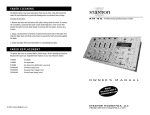
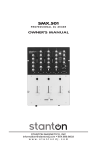
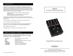
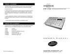
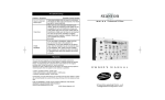
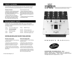
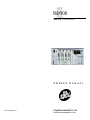
RM-50 Professional DJ mixer
OWNER’S M A N U A L
© 2001, Stanton Magnetics, LLC
STANTON MAGNETICS, LLC
[email protected]
T RO U B LE S H O OT I N G
Thank you for making Stanton your first choice in professional DJ mixers.
This new, innovative family of mixers has been developed with input from the professional DJ community, bringing to the marketplace a previously unavailable, affordable combination of user-friendly, functional design, rugged construction, and professional quality features.
Problem
Cause
Solution
Excessive hum when using
phono source.
Poor ground connection.
Properly connect turntable
ground wire to mixer ground
terminal.
Loose cartridge/headshell
connection.
Check cartridge connection
to headshell. Check headshell connection to tonearm.
Low frequency hum while
operating source unit.
Poor AC source ground.
Loose input/output connection. Shorted cable.
Properly ground the AC
source. Check all input and
output connections for
secure fit. Isolate and replace
the damaged cable.
Program volume can’t be
adjusted with master volume
control.
Amplifier or outboard gear
connected to the record output.
Connect amplifier or outboard
gear to master output.
No power.
Improperly connected AC cord
or power line source not on.
Properly connect AC cord to
AC power source. Turn power
on.
Blown fuse.
Remove the fuse cover with a
flat-bladed screwdriver.
Replace fuse with a new
500mA fuse.
Faulty output connections
Properly connect amplifier, or
outboard gear to mixer.
Improper level adjustment.
Properly set crossfader,
channel faders, gain controls, and input selector toggles.
Stanton and your authorized Stanton dealer are dedicated to your complete satisfaction by offering benchmark service and support throughout the long life of your
Stanton product.
Again, we appreciate your patronage, and look forward to many years of making
music together.
PLEASE READ CAREFULLY BEFORE USE OF THIS PRODUCT
FAILURE TO FOLLOW THE INSTRUCTIONS PRINTED BELOW MAY VOID WARRANTY
• Follow all security advice printed on your mixer
• When removing the unit's AC plug from the power source, grasp and pull the
plug, NEVER the cord itself!
• Avoid placing your mixer near heat sources, such as power amplifiers.
• When in use, place your mixer on a stable surface, away from vibration. Always
use care when carrying your mixer. Impact, or heavy vibration may compromise
the unit's mechanical integrity. The manufacturer is not responsible for damage
resulting from an impact, or misuse.
• When in use, place your mixer away from sources of hum or noise, such as
transformers, or electric motors.
The amplifier is turned up,
but there is no signal.
• To prevent overheating, always provide your mixer with adequate ventilation
air space.
• Avoid stepping on your mixer's AC cord. Repeated compression of the cord
may lead to electrical shorting.
• To avoid damage due to AC voltage peaks, always disconnect your mixer from
the power source during electrical storms.
• Your mixer contains no user-serviceable parts. The manufacturer is not
responsible for any damage or personal injury resulting from unauthorized
user-servicing or modifications. In addition, the warranty will be void if any
unauthorized service by the user is detected. Always return you mixer to an
authorized Stanton dealer for servicing.
No signal in headphones.
Improper connection.
Improper level or cue mix
settings.
Check headphone connection to mixer. Tighten if necessary.
Adjust headphone level and
cue mix to the proper level
and channel settings.
D E S C R I P T I ON O F F U N C TI O N S
1. BNC jack: 12V gooseneck light input
2. Power switch: Selects power "ON" or "OFF"
3. Mono/stereo switch: switches the of Master output between a stereo and mono signal
4. Master balance control: Controls left/right signal balance of the master output.
5. Headphone level control: Controls the overall headphone output level. It is recommended headphones with an impedance rating of 200 ohms or less be used for maximum volume.
6. Headphone output: Connection for 1/4 inch headphone. Recommended headphone
impedance is 32-200 ohms for maximum volume.
7. Booth level control: Controls the signal level of the booth output.
8. Cue pan: Fades the headphone output between the channel(s) selected by the cue
assign switches (17) and the master one output, effectively allowing the user to preview a mix.
9. Master level control: Controls the overall signal output level of the master output.
10. Equalizer: Individual controls for low frequency, midrange, and high frequency
equalization with (+10/-10 dB) Note: Any changes made to EQ settings will change the
overall output level.
11. Crossfader source selectors: When set to A, the select channel will be assigned to the
left side of the crossfader. when set to B, the selected channel will be assigned to the
right side of the crossfader. When set to BYPASS, the crossfader will be bypassed
altoghter.
12 . Crossfader: Fades the master output between the channels selected by the
Crossfader source selectors (13).
13. Cue assign switch: Selects the channel to be monitored.
14. Fader Start: Turns the fader start function ON or OFF. The fader start will work with CD
players (such as Stanton’s S-Series) to start the audio from the CD player’s cue point.
15. Channel fader: Controls the input channel level.
16. Microphone volume: Controls the output levels of mics 1, 2, and 3.
17. Mic selector: Turns the mic on or off and activates the automatic talkover circuit.
When activated, the automatic talkover circuit reduces the music output based on the
setting of the talkover attenuation control (19).
18. Mic EQ: Individual controls for low frequency and high frequency equalization with
(+10/-10 dB) for mics 1, 2, and 3. Note: Any changes made to EQ settings will change
the overall output level.
19. Microphone 1 and 2 inputs: Combo connector is for mic 1, and the 1/4” connector is
for mic 2.
20. Input Level meter: Displays the input level. The input level is determined by the input
channel controls (24).
21. Input selector switches: Selects phono or line input.
22. Output Level meter: Displays the overall signal level of the master output.
23. Fader Start connector: Connects to the sound module’s remote start output (such as
Stanton’s S-Series CD players) to control the cue-start via the mixer’s crossfader.
24. Audio signal inputs: Line inputs are used to connect to line level sources such as CD
players, samplers, tape players, etc. Phono inputs are used to connect to turntables.
Mic inputs connect directly to microphones. To prevent potential circuit damage, never
connect line level source to phono inputs.
25. Audio signal outputs: Master output connects to an amplifier, EQ, crossover, or other
outboard signal processing. Record out connects to tape recorder, mini disk recorder,
etc. Booth output is a second master output used mostly for in-booth monitoring.
26. AC cord connector: Input connection for the supplied removable AC cord.
FA D E R C LE A N I N G
TE C H N I C A L S P E C I FI C AT I O N S
3. Shake and wipe off excess fluid before re-assembling the fader.
Line inputs:
Phono inputs:
DJ mic input:
Master output:
Booth output:
Record output:
Headphone output:
Frequency Response:
Tone Control :
Mic Tone:
Gain Control:
S/N Ratio:
T.H.D:
Dimension(LxWxD):
FA D E R R E P L AC E M E N T
WA R R A N T Y
The RM-50 faders may need lubrication from time to time. This will extend the
fader life and eliminate any potential damage due to extended heavy usage.
Cleaning Instructions
1. Remove the fader and disconnect the cable coming from the mixer. To remove
the crossfader, unscrew the outer screws (removing the 2 inner screws will
detach the fader from the fader plate). To remove the line faders, remove all 4
screws.
2. Spray a small amount of cleaner or lubricant into both ends of the fader and
slide the fader back and forth a few times to spread the fluid evenly throughout
the fader.
To replace the cross or channel faders, follow step 1 of the cleaning instructions.
Replacement parts are available from Stanton or your local Stanton dealer.
CF-RM19
Crossfader
LF-RM19
Line input fader
RF-RM19
PS-RM19US
PS-RM19EU
PS-RM19UK
Line input rotary (dial) fader
US Power Supply (110v)
European Power Supply (220v)
UK only Power Supply (240v)
8 (RCA), 150 mV / 27K ohm
4 (RCA), 3 mV / 47K ohm
3 (XLR, 1/4“), 2.45 mV / 3K ohm
1 (RCA), 1.2 V / 1K ohm
1 (RCA), 1.2 V / 1K ohm
1 (RCA), 245 mV / 10K ohm
1 (1/4”), 32 - 200 ohms recommended
20 Hz - 20 kHz, +/- 2 dB
+ 9/-60 dB (Hi, Mid, Low)
Hi/Lo +/-10 dB
0-20dB
Less than 70dB
less than 0.2%
5.25” x 19” x 7” (134 x 482 x 178 mm) 3U
This unit has been designed and manufactured using quality
components. Therefore, it is warranted to be free from defects in materials (limited as specified below), and workmanship for a period of twelve
(12) months from the original purchase date. During this period, all
service and parts necessary to repair a defect will be free of charge. This
limited warranty applies to mechanical parts which are subject to wear
and tear as specified:
• Faders, specified durability: 15,000 cycles
• Rotary potentiometers, specified durability: 10,000 cycles
• Switches, specified durability: 10,000 cycles
Consequently, the parts listed above are warranted to be free from
defects in materials and workmanship for a period of thirty days (30)
days from the original purchase date.
FOR THE WARRANTY TO BE VALID, PLEASE COMPLETE THE
ONLINE WARRANTY REGISTRATION FORM FOUND AT
WWW.STA N TO N M AG N E TI CS . CO M
Stanton Magnetics, LLC,
Hollywood, FL 33020