1
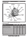
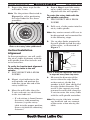
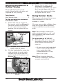
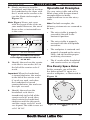
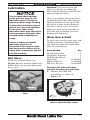
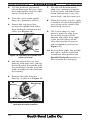
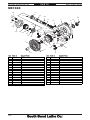
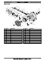
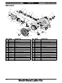
ROTARY TABLE
MODEL SB1363 4"
MODEL SB1364 6"
MODEL SB1367 8"
MODEL SB1368 10"
OWNER'S MANUAL
Hundreds of Thousands of Lathes Sold With a Tradition of Q uality Since 1906!
Copyright © July, 2010
For Equipment Mfg. Since 10/09
Scope Of Manual
This manual helps the reader understand the equipment, how to prepare it
for operation, how to control it during operation, and how to keep it in good
working condition. We assume the reader has a basic understanding of how
to operate this type of equipment, but that the reader is not familiar with the
controls and adjustments of this specific model. As with all equipment of this
nature, learning the nuances of operation is a process that happens through
training and experience. If you are not an experienced operator of this type
of equipment, read through this entire manual, then learn more from an
experienced operator, schooling, or research before attempting operations.
Following this advice will help you avoid serious personal injury and get the
best results from your work.
Manual Feedback
We've made every effort to be accurate when documenting this item.
However, errors sometimes happen or the design changes after the
documentation process—so the manual may not exactly match the item you
received. If a difference between the manual and what you received leaves
you in doubt, contact our customer service for clarification.
We highly value customer feedback on our manuals. If you have a moment,
please share your experience using this manual. What did you like about
it? Is there anything you would change to make it better? Did it meet your
expectations for clarity, professionalism, and ease-of-use?
South Bend Lathe, Inc.
C
/O Technical Documentation Manager
P.O. Box 2027
Bellingham, WA 98227
Email: [email protected]
Updates
For your convenience, any updates to this manual will be available to
download free of charge through our website at:
www.southbendlathe.com
Customer Service
We stand behind our equipment. If you have any service questions, parts
requests or general questions about your purchase, feel free to contact us.
South Bend Lathe Co.
P.O. Box 2027
Bellingham, WA 98227
Fax: (360) 734-1639 (USA Only)
Phone: (360) 734-1540
Fax: (360) 676-1075 (International)
Email: [email protected]
Table of Contents
introduction
Identification....................................................................................................... 2
Specifications...................................................................................................... 2
Safety
Understanding Risks of Machinery................................................................... 3
Basic Machine Safety......................................................................................... 3
PREPARATION
Preparation Overview........................................................................................ 5
Required for Setup.............................................................................................. 5
Inventory............................................................................................................. 5
Cleaning & Protecting........................................................................................ 6
Installation.......................................................................................................... 7
Horizontal Installation....................................................................................... 7
Vertical Installation........................................................................................... 8
Aligning to Spindle Centerline.......................................................................... 8
Horizontal Installation Alignment. ..................................................................... 9
Vertical Installation Alignment. ....................................................................... 10
OPERATION
Controls & Components................................................................................... 11
Aligning Handwheel & Vernier Scales............................................................ 12
Using Vernier Scale.......................................................................................... 12
Operational Examples...................................................................................... 13
Five Evenly Space Holes................................................................................... 13
Two Circular Slots. .......................................................................................... 14
MAINTENANCE
Maintenance Schedule..................................................................................... 16
Cleaning & Protecting...................................................................................... 16
Surface Care..................................................................................................... 16
Lubrication........................................................................................................ 17
Ball Oilers....................................................................................................... 17
Worm Gear & Shaft. ........................................................................................ 17
SERVICE
Spindle Preload................................................................................................. 19
PARTS
SB1363.............................................................................................................. 20
SB1364.............................................................................................................. 21
SB1367.............................................................................................................. 22
SB1368.............................................................................................................. 23
WARRANTY.............................................................................................................................. 25
SB1363-64/SB1367-68
Mfg. Since 10/09
IN T R O D U C T I O N
Identification
Horizontal
Mounting Slot
Rotation
Scale
Table
Lock
Spindle
Bore
Backlash
Adjustment Ring
Table
Lock
Vernier
Scale
Rotary
Handwheel
Vertical
Mounting
Holes
Backlash
Adjustment Lock
Handwheel
Scale
Backlash
Ring Lever
Figure 1. Identification (Model SB1367 shown).
Specifications
Description
SB1363
SB1364
SB1367
SB1368
Clamping Surface Flatness (Concave)
0.0008"
0.0008"
0.0008"
0.0008"
Spindle Bore Concentricity
0.0008"
0.0008"
0.0010"
0.0010"
Surface to Base Parallelism
0.0008"
0.0008"
0.0008"
0.0008"
Surface to Angle Face Squareness
0.0008"
0.0008"
0.0008"
0.0008"
3.05"
3.30"
4.17"
4.50"
Overall Height (Horizontal)
Height to Center of Spindle Bore
3.20"
3.94"
5.12"
6.38"
Morse Taper
MT#1
MT#2
MT#3
MT#3
T-Slot Width (6 Each)
0.393"
0.433"
0.433"
0.512"
Table Diameter
3.94"
5.90"
8.03"
10.00"
Shipping Weight
16 lbs.
28 lbs.
62 lbs.
98 lbs.
-2-
Mfg. Since 10/09
SAFETY
SB1363-64/SB1367-68
Understanding Risks of Machinery
Operating all machinery and machining equipment can be dangerous or
relatively safe depending on how it is installed and maintained, and the
operator's experience, common sense, risk awareness, working conditions, and
use of personal protective equipment (safety glasses, respirators, etc.).
The owner of this machinery or equipment is ultimately responsible for its safe
use. This responsibility includes proper installation in a safe environment,
personnel training and usage authorization, regular inspection and
maintenance, manual availability and comprehension, application of safety
devices, integrity of cutting tools or accessories, and the usage of approved
personal protective equipment by all operators and bystanders.
The manufacturer of this machinery or equipment will not be held
liable for injury or property damage from negligence, improper training,
machinemodifications, or misuse. Failure to read, understand, and follow the
manual and safety labels may result in serious personal injury, including
amputation, broken bones, electrocution, or death.
The signals used in this manual to identify hazard levels are defined
as follows:
Death or catastrophic harm WILL occur.
Death or catastrophic harm COULD occur.
Moderate injury or fire MAY occur.
Machinery or property damage may occur.
Basic Machine Safety
Owner’s Manual: All machinery
and machining equipment presents
serious injury hazards to untrained
users. To reduce the risk of injury,
anyone who uses THIS item MUST
read and understand this entire
manual before starting.
Entanglement: Loose clothing, gloves,
neckties, jewelry or long hair may
get caught in moving parts, causing
entanglement, amputation, crushing,
or strangulation. Reduce this risk
by removing/securing these items so
they cannot contact moving parts.
Properly Functioning Equipment:
Poorly maintained, damaged, or
malfunctioning equipment has
higher risks of causing serious
personal injury compared to those
that are properly maintained. To
reduce this risk, always maintain
this item to the highest standards
and promptly repair/service
a damaged or malfunctioning
component. Always follow the
maintenance instructions included in
this documentation.
Trained/Supervised Operators Only:
Untrained users can seriously injure
themselves or bystanders. Only allow
trained and properly supervised
personnel to operate this item. Make
sure safe operation instructions are
clearly understood. If machine is
electrically powered, use padlocks
and master switches, or remove start
switch keys to prevent unauthorized
use or accidental starting. If machine
cannot be locked out, restrict access
to the shop.
-3-
SB1363-64/SB1367-68
SAFETY
Personal Protective Equipment:
Operating or servicing this item
may expose the user to flying debris,
dust, smoke, dangerous chemicals,
or loud noises. These hazards can
result in eye injury, blindness, longterm respiratory damage, poisoning,
cancer, reproductive harm or hearing
loss. Reduce your risks from these
hazards by wearing approved eye
protection, respirator, gloves, or
hearing protection.
Safe Environment: Operating
electrically powered equipment in
a wet environment may result in
electrocution; operating near highly
flammable materials may result in
a fire or explosion. Only operate this
item in a dry location that is free
from flammable materials.
Unattended Operation: Electrically
powered equipment that is left
unattended while running cannot
be controlled and is dangerous to
bystanders. Always turn the power
OFF before walking away.
Guards/Covers: Accidental contact
with moving parts during operation
may cause severe entanglement,
impact, cutting, or crushing injuries.
Reduce this risk by keeping any
included guards/covers/doors
installed, fully functional, and
positioned for maximum protection.
Difficult Operations: Attempting
difficult operations with which you
are unfamiliar increases the risk of
injury. If you experience difficulties
performing the intended operation,
STOP! Seek an alternative method
to accomplish the same task, ask a
qualified expert how the operation
should be performed, or contact our
Technical Support for assistance.
Chuck Keys or Adjusting Tools: Tools
used to adjust spindles, chucks,
or any moving/rotating parts will
become dangerous projectiles if left
in place when the machine is started.
Reduce this risk by developing the
habit of always removing these tools
immediately after using them.
-4-
Mfg. Since 10/09
Secure Workpiece/Tooling: Loose
workpieces, cutting tools, or rotating
spindles can become dangerous
projectiles if not secured or if they
hit another object during operation.
Reduce the risk of this hazard by
verifying that all fastening devices
are properly secured and items
attached to spindles have enough
clearance to safely rotate.
Disconnect Power: Adjusting or
servicing electrically powered
equipment while it is connected to
the power source greatly increases
the risk of injury from accidental
startup. Always disconnect power
BEFORE any service or adjustments,
including changing blades or other
tooling.
Electrical Connection: With
electically powered equipment,
improper connections to the power
source may result in electrocution or
fire. Always adhere to all electrical
requirements and applicable codes
when connecting to the power
source. Have all work inspected by a
qualified electrician to minimize risk
of electrocution or fire.
Mental Alertness: Operating this
item with reduced mental alertness
increases the risk of accidental
injury. Do not let a temporary
influence or distraction lead to a
permanent disability! Never operate
when under the influence of drugs/
alcohol, when tired, or otherwise
distracted.
Health Hazards: Certain cutting
fluids and lubricants, or dust/
smoke created when cutting,
may contain chemicals known to
the State of California to cause
cancer, respiratory problems, birth
defects, or other reproductive
harm. Minimize exposure to these
chemicals by wearing approved
personal protective equipment and
operating in a well ventilated area.
Work Area: Clutter and dark
shadows increase the risk of
accidental injury. Only operate this
item in a clean, non-glaring, and
well-lighted work area.
Mfg. Since 10/09
P R E P A R AT I O N
SB1363-64/SB1367-68
Preparation Overview
Inventory
The purpose of the preparation
section is to help you prepare your
rotary table for operation. The list
below outlines the basic process.
Specific steps for each of these
points will be covered in detail later
in this section.
This item was carefully packaged to
prevent damage during transport.
If you discover any damage, please
immediately call Customer Service
at (360) 734-1540 for advice. You
may need to file a freight claim, so
save the containers and all packing
materials for possible inspection by
the carrier or its agent.
The typical preparation process is as
follows:
1. Unpack the tool and inventory
the contents.
Description (Figure 2)
Qty
A. Rotary Table . . . . . . . . . . . . . . . 1
B. Handwheel Handle. . . . . . . . . . 1
2. Clean the tool and its
components.
A
3. Install the rotary table on
the mill table horizontally or
vertically.
4. Align the rotary table with the
mill spindle centerline.
Required for Setup
B
Figure 2. Shipping inventory.
The items listed below are required
to successfully set up and prepare
this tool for operation.
•
•
•
•
Safety glasses
Cleaner/degreaser (see Page 6)
Clamping hardware and tools
Custom keys for horizontal
installation (see Page 7)
(Optional)
• Machinist's square
• Test indicator
• Edge finder (Optional)
-5-
SB1363-64/SB1367-68
P R E P A R AT I O N
Cleaning & Protecting
The unpainted surfaces are coated
at the factory with a heavy-duty
rust preventative that prevents
corrosion during shipment and
storage.The benefit of this rust
preventative is that it works very
well. The downside is that it can
be time-consuming to thoroughly
remove.
Be patient and do a careful job when
cleaning and removing the rust
preventative. The time you spend
doing this will reward you with
smooth-sliding parts and a better
appreciation for the proper care of
the unpainted surfaces.
Although there are many ways
to successfully remove the rust
preventative, we have cleaned
thousands of machines and found
the following process to be the best
balance between efficiency and
minimized exposure to toxic fumes
or chemicals.
Before cleaning, gather the
following:
•
•
•
Disposablerags
Cleaner/degreaser (certain
citrus-based degreasers work
extremely well and they have
non-toxic fumes)
Safetyglasses&disposable
gloves
Note: Automotive degreasers,
mineral spirits,orWD•40canbe
used to remove rust preventative.
Before using these products, though,
test them on an inconspicuous area
of a painted area to make sure they
will not damage it.
-6-
Mfg. Since 10/09
Basic steps for removing rust
preventative:
1. Put on safety glasses and
disposable gloves.
2. Coatallsurfacesthathave
rust preventative with a liberal
amount of your cleaner or
degreaser and let them soak for
a few minutes.
3. Wipe off the surfaces. If your
cleaner or degreaser is effective,
the rust preventative will wipe
off easily.
Note: To clean off thick coats of rust
preventative on flat surfaces,
such as beds or tables, use
aPLASTICpaintscraperto
scrape off the majority of the
coating before wiping it off with
yourrag.(Donotuseametal
scraper or it may scratch the
surface.)
4. Repeat Steps 2–3 as necessary
until clean, then coat all
unpainted surfaces with a
quality metal protectant or light
oil to prevent rust.
Gasoline and petroleum
products have low flash points
and can explode or cause fire if
used for cleaning. Avoid using
these products to remove rust
preventative.
Many cleaning solvents are toxic
if inhaled. Minimize your risk by
only using these products in a
well ventilated area.
Mfg. Since 10/09
P R E P A R AT I O N
Installation
Before installing the rotary
table, make sure that the spindle
centerline is properly aligned or
"trammed" with the mill table. Also,
remove any burrs or scratches from
the mating surfaces of the rotary
and mill table by "stoning" them,
then thoroughly wipe them clean
and dry (refer to the Surface Care
section on Page 16 for detailed
instructions).
Horizontal Installation
The horizontal base has slots (see
Figure 3) that accept keys for
quick alignment with the mill table.
Because of the many variations in
mill table T-slots, these keys are not
provided with the rotary table. If
you choose to use keys for alignment
when installing the rotary table
horizontally, you will have to
machine them to fit the rotary table
and your mill table.
Mounting
Slots
Key Slots
Figure 3. Locations of the horizontal
base key slots and mounting slots
(Model SB1363 shown).
SB1363-64/SB1367-68
To mount the rotary table
horizontally:
1. DISCONNECT MILL FROM
POWER!
2. Position the rotary table
horizontally on the mill table so
that the mounting slots shown
in Figure 3 are aligned with the
mill table center T-slot.
Make sure the rotary
table handwheel is free of
obstructions. Depending on your
setup, the rotary table may need
to be blocked up or mounted so
the handle is hanging over the
edge of the mill table.
3. Attach the rotary table to the
mill table with the clamping
hardware, but leave the
fasteners loose for now.
4. Place the machinist's square
along the front edge of the mill
table and the machined foot
of the rotary table, square the
rotary table to the mill table,
then fully tighten the clamping
fasteners.
You MUST properly secure the
rotary table to the mill table to
prevent unexpected movement
of the rotary table and workpiece
during operation, which could
result in personal injury or
workpiece damage.
5. Perform the Horizontal
Installation Alignment
procedure as instructed on
Page 9.
-7-
SB1363-64/SB1367-68
P R E P A R AT I O N
Vertical Installation
Compare the center to center
distance between the mill table
T-slots to the vertical mounting
holes on the rotary table foot (see
Figure 4). If the mounting holes do
not intersect the mill table T-slots
with sufficient space for T-bolts, use
step blocks and clamps in place of
one of the T-bolts.
Mfg. Since 10/09
3. Place the rotary table on the
mill table so that you can use
the clamping hardware to secure
it in the next step.
4. Place the machinist's square
along the front of the mill table
and the machined side of the
rotary table foot, square the
rotary table to the mill table,
then fully tighten the clamping
hardware.
5. Perform the Vertical
Installation Alignment
procedure as instructed on
Page 10.
Vertical
Mounting Holes
Figure 4. Locations of the vertical
mounting holes.
To mount the rotary table vertically:
1. DISCONNECT MILL FROM
POWER!
2. Insert the clamping hardware
into the outer mill table T-slots.
Make sure the rotary
table handwheel is free of
obstructions. Depending on your
setup, the rotary table may need
to be blocked up or mounted so
the handle is hanging over the
edge of the mill table.
-8-
Aligning to Spindle
Centerline
Whether the rotary table is mounted
horizontally or vertically, you must
align the rotary table centerline
to the mill spindle centerline to
achieve quality results. Also, the
spindle centerline must first be
properly aligned to mill table in both
the X- and Y- axis (this procedure
is generally called "tramming the
spindle").
There are many methods for
aligning the centerlines, and it
is up to the machinist and their
capabilities to decide which
approach is best.
Mfg. Since 10/09
P R E P A R AT I O N
Horizontal Installation
Alignment
Two methods are described below
for aligning the mill spindle and
rotary table centerlines when the
rotary table is mounted horizontally.
To use a test indicator to align the
rotary table:
1. DISCONNECT MILL FROM
POWER!
2. Mount the test indicator to the
mill spindle offset from the
spindle centerline by the radius
of the rotary table spindle bore,
then position the tip on the
inside vertical surface of the
rotary table spindle bore (see
Figure 5 for an example).
SB1363-64/SB1367-68
6. Repeat Step 5 until the test
indicator reads zero deviation in
all four directions.
Tip: Use a mirror to read the
indicator when it is facing away
from you.
To use an edge finder to align the
rotary table:
1. Mount an edge finder into the
mill spindle, then position it
roughly in the center of the
rotary table spindle bore and
below the rotary table surface.
2. Set the mill spindle speed to
800–1000 RPM, then turn the
mill ON.
3. Slowly move the mill table along
the X-axis in one direction until
the edge finder meets the edge
of the rotary table spindle bore,
then note the position of the
table on the handwheel dial.
Note: When recording the mill table
position, take into account the
backlash that is usually present
in the leadscrew.
Figure 5. Example of using a test
indicator to align a rotary table.
3. Turn the mill spindle by hand so
that the test indicator is aligned
to the X-axis of the mill table.
Note: For best results, turn the mill
spindle in only one direction.
4. Slowly move the mill table until
the test indicator reads zero
deviation.
5. Rotate the mill spindle and
test indicator 90°, then repeat
Step 4.
4. Slowly move the mill table in
the opposite direction until
you again find the edge of the
spindle bore, then note the table
position on the handwheel dial.
5. Calculate the difference of
the mill table positions from
Steps 3–4.
6. Move the mill table 1⁄2 the
amount calculated in Step 5
along the X-axis. Be sure to take
into account any backlash.
-9-
SB1363-64/SB1367-68
P R E P A R AT I O N
7. Repeat the above steps for the
mill table Y-axis.
Note: Use the pattern illustrated in
Figure 6 to aid in positioning
the edge finder for the above
procedure.
2
5
6 3 4
1
Figure 6. Pattern of positioning the edge
finder to the rotary table spindle bore.
Vertical Installation
Alignment
Mfg. Since 10/09
4. Repeat Step 3 until the entire
rotary table surface is correctly
aligned with the mill spindle.
To center the rotary table with the
mill spindle centerline:
1. DISCONNECT MILL FROM
POWER!
2. Fully seat a lathe center into the
rotary table spindle.
Note: Any center runout will have to
be determined and accounted for
in the following steps.
3. Use an edge finder mounted in
the mill spindle to find the edge
of the center, as illustrated in
Figure 7.
Top View
In these procedures, you will verify
the rotary table alignment with the
mill spindle from front to back and
to its centerline.
To verify the front-to-back alignment
of the rotary table to the mill
spindle:
1. DISCONNECT MILL FROM
POWER!
2. Mount a test indicator to the
mill spindle and position the
indicator tip on one end of the
rotary table face.
3. Move the mill table along the
Y-axis and note any deviations
in the test indicator.
—If a deviation is found, loosen
the rotary table mounting
fasteners, tap the rotary
table into the proper position,
then re-tighten the mounting
fasteners.
-10-
Rotary
Table
Edge
Finder
Lathe
Center
Figure 7. Using an edge finder and center
to align the rotary table (top view).
4. Measure the diameter of the
center where the edge finder
makes contact, divide this
number in half, then add half of
the edge finder diameter. The
result is the amount you need
to move the mill table along the
Y-axis to center the rotary table
with the mill spindle centerline.
Note: Be sure to take into account
any backlash and any rounout
of the center when moving the
table.
Mfg. Since 10/09
O P E R AT I O N
SB1363-64/SB1367-68
C. Vernier Scale: Displays the
amount of table rotation with
a resolution of 10" (ten arc
seconds).
D. Rotation Scale: Displays the
table position in whole degrees.
To reduce the risk of serious
injury when using this
equipment, read and understand
this entire manual before
beginning any operations.
Controls & Components
Refer to Figure 8 and the following
descriptions to become familiar with
the controls and components used to
operate the rotary table.
D
E
C
B
F
A
H
G
Figure 8. Rotary table controls and
components (Model SB1367 shown).
A. Handwheel: Rotates the table
when the gears are engaged.
B. Handwheel Scale: Displays the
amount of the table rotation
with a resolution of 1' (one arc
minute) and also in 1° marks.
One complete revolution of the
handwheel rotates the table 4°.
E. Table Locks: When fully
tightened, keep the table from
rotating to reduce the strain
on the gears during operation.
When cutting circular slots, a
slight drag can be applied with
the table locks to help reduce
chatter caused by gear backlash.
F. Spindle Bore: Holds a center to
support a workpiece for dividing
work. Also, used in rotary table
alignment with the mill spindle
centerline.
G. Backlash Adjustment
Lock: Secures the backlash
adjustment ring in place.
H. Backlash Adjustment Ring
Lever: Conveniently controls the
backlash adjustment ring for
adjusting the backlash between
the gears.
When rotated completely
clockwise, the backlash
adjustment ring disengages the
gears so that the table can be
rotated by hand.
Note: The Model SB1368 uses
a knurled ring instead of a
lever.
-11-
SB1363-64/SB1367-68
O P E R AT I O N
Aligning Handwheel &
Vernier Scales
The handwheel scales can be
easily aligned with each other and
adjusted for easy viewing.
Tools Needed
Qty
Hex Wrench 5mm. . . . . . . . . . . . . . 1
To align and adjust the handwheel
and vernier scales:
1. Loosen the two set screws on
the vernier scale (see Figure 9),
rotate the vernier scale so that
it is in a convenient viewing
position, the re-tighten the set
screws.
Handwheel Scale
Set Screw
3. Loosen the set screw on the
handwheel (see Figure 9),
rotate the handwheel scale until
the 0° mark aligns with the 0°
mark on the vernier scale, then
re-tighten the set screw.
Using Vernier Scale
The vernier scale is used to measure
table rotation by 10" (ten arc
seconds) at a time.
Use your rotary table to follow along
with the example below to better
understand how to use the vernier
scale.
Note: This example assumes the
table rotation position is at 0°, and
the handwheel and vernier scales
are aligned at 0°.
To set the table at 16° 32' 20":
1. With the table at 0°, rotate the
handwheel clockwise four full
turns, which will rotate the
table 16°.
Vernier Scale Set Screw
(1 of 2)
Figure 9. Locations of the handwheel and
vernier scale set screws
2. Use the handwheel to rotate the
table until the 0° on the table
rotation scale aligns with the
center mark on the pointer (see
Figure 10).
Pointer
Rotation
Scale
Figure 10. Location of the rotation scale
pointer.
-12-
Mfg. Since 10/09
—If you go past the handwheel
scale 0° mark on the fourth
turn, rotate the table
counterclockwise 1⁄2 turn,
then start again.
Note: When changing direction
with the handwheel, take into
account any backlash.
Mfg. Since 10/09
Operational Examples
2. Slowly continue to turn the
handwheel until the 32' mark on
the handwheel scale aligns with
the 0° mark on the vernier scale
(see the illustrated example in
Figure 11).
Use your rotary table and mill to
follow along with the operational
examples below to better
understand how to use the rotary
table.
Note: Figure 11 may not agree
with the layout of the scales on
your model. However, the use of
these scales as instructed here
is the same.
Note: For both examples, the
following statements are assumed to
be true:
20 Arc Seconds
60
40 30 20 10
1
50
SB1363-64/SB1367-68
O P E R AT I O N
0 Vernier Scale
40
Handwheel Scale
30
20
10
32 Arc Minutes
Figure 11. Handwheel and vernier
scales aligned so that the table is at
16° 32' 20".
3. Identify the mark on the vernier
scale that is two marks (20") to
the left of the vernier scale 0°
mark.
Important: When the handwheel
is turned clockwise, the marks
to the left of the vernier scale
0° mark are used, and when
the handwheel is turned
counterclockwise, the marks on
the right are used.
4. Identify the mark on the
handwheel scale that is
immediately to the left of the
vernier scale 20" mark, then
slowly rotate the handwheel
clockwise until the this mark
and the vernier scale 20" mark
are aligned. The table is now set
at 16° 32' 20".
0
50
• The rotary table is properly
secured to the mill in the
horizontal position.
• The rotary table is properly
centered with the mill spindle
centerline.
• The workpiece is centered and
properly clamped on the rotary
table, and elevated for proper
machining clearances.
• The 0° marks of the handwheel
and vernier scales are aligned.
Five Evenly Space Holes
In this example, you will make
five holes spaced 72° apart in a
circular workpiece, as illustrated in
Figure 12.
72º
Figure 12. Five hole layout spaced 72°
apart.
-13-
SB1363-64/SB1367-68
Mfg. Since 10/09
O P E R AT I O N
Tip: When using the rotary table
to machine several locations or
with a complicated pattern, make a
drawing with measurement details
to help visualize the operation. This
will reduce the risk of making errors
during the operation.
To make five evenly spaced holes:
1. Use the handwheel to rotate the
rotary table to the 0° mark on
the rotation scale, then tighten
both table locks.
Two Circular Slots
In this example, you will cut two 92°
circular slots in a round workpiece,
as illustrated in Figure 13.
92º
Radius
1.125"
0.25"
Start
Here
2. Drill the first hole.
3. Unlock the table, then turn
the handwheel 18 full turns.
This will rotate the rotary table
to 72°, as displayed on the
rotational scale.
Important: Be careful not to pass the
handwheel scale 0° mark on the
last turn. If you go past the 0°
mark, reverse the handwheel
one full turn, then try again.
This will eliminate any backlash
error that occurs when reversing
the handwheel direction.
4. Lock the table in place and drill
the hole.
5. Repeat Steps 3–4 to produce
the third hole at 144°, the fourth
hole at 216°, and the fifth hole
at 288°.
-14-
Figure 13. Layout for creating two
circular slots.
To make two circular slots:
1. Use the handwheel to rotate
the rotary table to the 0° mark
on the rotational scale, then
tighten the table locks.
2. Move the mill table to the left
1.125" along the X-axis so that
the spindle is at the starting
point above the lower end of the
upper slot.
3. Install a 1⁄4" end mill in the mill
spindle, then make a 0.083"
deep hole (approximately 1⁄3 the
cutter diameter).
Mfg. Since 10/09
O P E R AT I O N
SB1363-64/SB1367-68
4. With the end mill continuing
to cut, turn the rotary table
handwheel clockwise 23 full
turns (92°), using care not to
pass the handwheel scale 0°
mark on the last turn.
6. Make a 0.083" deep hole, then
with the end mill continuing
to cut, turn the rotary table
handwheel clockwise 23 full
turns to begin the second 92°
slot.
5. Raise the end mill from the
workpiece, then rotate the
handwheel clockwise 45 full
turns (180°), making sure not
to pass the 0° mark. This will
bring the cutter to the starting
point of the second slot.
7. Raise the end mill, rotate the
rotary table clockwise back to
the 0° mark on the rotational
scale, then take an additional
0.083" deep cut.
Note: Rotating the rotary table in
only one direction throughout
the operation will remove any
error from backlash.
8. Repeat Steps 4–7, increasing
the depth of cut by 0.083" each
time, until the final depth of cut
is reached for each slot.
-15-
SB1363-64/SB1367-68
M A IN T E N A N C E
Mfg. Since 10/09
Maintenance Schedule
Cleaning & Protecting
For optimum performance from
your rotary table, follow this
maintenance schedule and refer to
any specific instructions given in
this section.
It is essential that the rotary table
be cleaned after every use. DO
NOT use compressed air to clean
your rotary table. Chips or debris
may become lodged between the
moving parts, reducing the life and
accuracy of the tool. Instead, use a
stiff-bristled brush to remove the
chips and swarf, then wipe down
the machined surfaces with a clean
shop rag before applying a thin
coat of light machine oil to prevent
corrosion.
Daily Before Use
• Lubricate the ball oilers
(Page 17).
• Check/resolve any unsafe
condition.
Daily After Use
• Clean the rotary table.
• Dress the machined surfaces.
• Lubricate the machined surfaces
to prevent rust.
Semi-Annually
• Disassemble and clean the
internal cavity of the rotary
table, then lubricate the worm
gear and shaft (Page 17).
Surface Care
Nicks, dings, and scratches on the
machined surfaces of the rotary
table can have an adverse effect
on accuracy and may damage the
workpiece or mill table.
Prior to use, dress or "stone" these
machined surfaces with a fine
sharpening stone. A few strokes
of the stone on the rotary table
surface, the machined base and
back, and the mill table will help
to ensure longevity and accuracy.
Make sure to thoroughly wipe these
surfaces clean to remove any dust
generated from the process, then
apply a thin coat of light machine oil
to prevent corrosion.
Tip: After stoning and wiping down
the surfaces, run your fingers lightly
across the surfaces to detect any
irregularities.
-16-
Mfg. Since 10/09
M A IN T E N A N C E
Lubrication
SB1363-64/SB1367-68
Important: Use an oil can or gun
that has a plastic or rubber tip.
Metal tips can damage the ball and
spring inside the oilers.
The recommended schedule
on the previous page for the
lubrication tasks is based on
light-to-medium usage. Keeping
in mind that lubrication helps to
protect the value and operation
of the rotary table, these
lubrication tasks may need to be
performed more frequently than
recommended, depending on
usage.
Failure to follow reasonable
lubrication practices as
instructed in this manual could
lead to premature failure of the
rotary table components and will
void the warranty.
Ball Oilers
There are two ball oilers (see
Figure 14) that must be lubricated
before daily use, or more often with
heavy use.
Clean away debris and grime from
around the ball oilers, then depress
the ball with the oil can tip to add
oil until it is seen exiting between
the parts. Clean away any excess
lubricant, then rotate the table at
least one full revolution to evenly
disperse the lubricant.
Worm Gear & Shaft
To gain access to the worm gear and
shaft for cleaning and lubrication,
you need to remove the table from
the cast iron housing.
Items Needed
Qty
Hex Wrench 3mm. . . . . . . . . . . . . . 1
Dead Blow Hammer. . . . . . . . . . . . . 1
Stiff-Bristled Brush. . . . . . . . . . . . . 1
Shop Rags. . . . . . . . . . . . . As Needed
Mineral Spirits. . . . . . . . . As Needed
MP Gear Grease. . . . . . . . As Needed
To remove the table and clean/
lubricate the worm gear and shaft:
1. Remove the table lock
assemblies, as shown in
Figure 15.
Ball Oilers
Figure 14. Locations of the two ball
oilers.
Figure 15. Table lock assemblies
removed (Model SB1364 shown).
-17-
SB1363-64/SB1367-68
M A IN T E N A N C E
2. Use the backlash adjustment
ring to disengage the gears from
the handwheel so that the table
rotates freely by hand.
3. Turn the rotary table upside
down on a protective surface.
4. Loosen the cap screw that
secures the spindle lock collar,
then unthread and remove the
collar (see Figure 16).
Lock
Collar
Figure 16. Loosening the spindle lock
collar cap screw.
5. Lift the edge of the cast iron
housing with one hand, and tap
the back end of the spindle with
the dead blow hammer until the
table assembly breaks free from
the housing.
6. Remove the table from the
housing, as shown in Figure 17.
Oil
Grooves
Worm Shaft
Worm Gear
Figure 17. Locations of worm gear and
shaft with the table removed.
-18-
Mfg. Since 10/09
7. Use the stiff-bristled brush,
shop rags, and mineral spirits
to clean grime and debris from
inside the housing cavity, the
worm shaft, and the worm gear.
8. When these parts are dry, apply
a medium coat of multi-purpose
gear grease to the teeth of the
worm shaft and gear.
9. Use a clean shop rag and
mineral spirits to wipe clean
the mating surfaces of the
housing and table, then apply
a thin coat of light machine
oil to the housing oil grooves
and surrounding surface (see
Figure 17).
10.Re-install the table, the spindle
lock collar, and the table lock
assemblies, then perform the
Spindle Preload procedure as
instructed on the next page.
Mfg. Since 10/09
SERVICE
Spindle Preload
Setting the spindle preload on the
rotary table affects the accuracy and
ease of use during operation.
Keep in mind, that too much preload
will make table rotation difficult
and will cause pre-mature wear of
the gears and mating surfaces of
the table. Conversely, not enough
preload may result in reduced
accuracy. Use your best judgment
when setting the spindle preload on
the rotary table.
Tool Needed
Qty
Hex Wrench 3mm. . . . . . . . . . . . . . 1
To set the rotary table spindle
preload:
1. Make sure the table locks are
loose.
2. Use the backlash adjustment
ring to disengage the worm
shaft from the worm gear so
that the table can be freely
rotated by hand and not the
handwheel.
SB1363-64/SB1367-68
4. From the back of the rotary
table, loosen the spindle lock
collar cap screw (see Figure 16
on the previous page).
5. Loosen the lock collar at least
two full turns to remove any
preload.
6. Rotate the table by hand as you
re-tighten the lock collar. When
it becomes difficult to turn the
table, back off the lock collar
slightly until the table rotates
freely again, then, while keeping
the lock collar from rotating, retighten the lock collar cap screw.
7. Use the backlash adjustment
ring to re-engage the worm
shaft and gear, then test the
table rotation by using the
handwheel.
—If you are not satisfied with
the table rotation, repeat
this procedure to re-adjust
the preload until you are
satisfied with the results.
3. Position the table in a vertical
position so that both the front
and the back are accessible.
-19-
SB1363-64/SB1367-68
Mfg. Since 10/09
PARTS
SB1363
25
16
17
15
30
14
28
8
13
9
10
32
20
26
24 23
6
22
12
11
29
5
21
19
7
18
4
1
2
36
37
3
6
11
31
7
5
REF PART #
DESCRIPTION
REF PART #
DESCRIPTION
1
2
3
4
5
6
7
8
9
10
11
12
13
14
15
16
17
TABLE
NEEDLE ROLLER BEARING NA4904
WORM GEAR
CAP SCREW M5-.8 X 20
CLAMP BOLT M6-1 X 25
CLAMP BOLT HANDLE M6-1 X 10
CLAMP
MAIN CASTING
THRUST NEEDLE BEARING 20 X 35 X 4
LOCK COLLAR M20-1
TAP-IN BALL OILER 1/4
BACKLASH ADJUST LOCK M6-1 X 14
POINTER
WORM SHAFT
ECCENTRIC WORM HOUSING
BACKLASH ADJUSTMENT RING
CAP SCREW M3-.5 X 12
18
19
20
21
22
23
24
25
26
28
29
30
31
32
36
37
VERNIER RING
SET SCREW M5-.8 X 10
BACKLASH RING LEVER
LOCK COLLAR M14-1.25
SET SCREW M4-.7 X 4
HANDWHEEL SCALE
HANDWHEEL
HANDWEEL HANDLE 3/8-16 X 1/2
FENDER WASHER 6MM
CAP SCREW M6-1 X 12
BACKLASH DIRECTION LABEL
KEY 4 X 4 X 7
TAPER SLEEVE MT#1
CAP SCREW M4-.7 X 8
SET SCREW M4-.7 X 20
HEX NUT M4-.7
-20-
PSB1363001
PSB1363002
PSB1363003
PCAP15M
PSB1363005
PSB1363006
PSB1363007
PSB1363008
PSB1363009
PSB1363010
PLUBE001
PSB1363012
PSB1363013
PSB1363014
PSB1363015
PSB1363016
PCAP164M
PSB1363018
PSS05M
PSB1363020
PSB1363021
PSS111M
PSB1363023
PSB1363024
PSB1363025
PWF06M
PCAP26M
PSB1363029
PK65M
PSB1363031
PCAP18M
PSS50M
PN04M
Mfg. Since 10/09
SB1363-64/SB1367-68
PARTS
SB1364
16
25
33
15
33 30
17
28
32
14
8
13
9
10
20
26
24 23
12 29
11
7
22
6
21
19
1
18
5
4
37
2
31
3
36
6
7
11
5
REF PART #
DESCRIPTION
REF PART #
DESCRIPTION
1
2
3
4
5
6
7
8
9
10
11
12
13
14
15
16
17
TABLE
NEEDLE ROLLER BEARING NK3520
WORM GEAR
CAP SCREW M5-.8 X 20
CLAMP BOLT M6-1 X 25
CLAMP BOLT HANDLE M6-1 X 10
CLAMP
MAIN CASTING
THRUST NEEDLE BEARING 25 X 42 X 4
LOCK COLLAR M24-1.5
TAP-IN BALL OILER 1/4
BACKLASH ADJUST LOCK M6-1 X 14
POINTER
WORM SHAFT
ECCENTRIC WORM HOUSING
BACKLASH ADJUSTMENT RING
CAP SCREW M3-.5 X 12
18
19
20
21
22
23
24
25
26
28
29
30
31
32
33
36
37
VERNIER RING
SET SCREW M5-.8 X 10
BACKLASH RING LEVER
LOCK COLLAR M14-1.25
SET SCREW M4-.7 X 4
HANDWHEEL SCALE
HANDWHEEL
HANDWEEL HANDLE 3/8-16 X 1/2
FENDER WASHER 6MM
CAP SCREW M6-1 X 12
BACKLASH DIRECTION LABEL
KEY 4 X 4 X 7
TAPER SLEEVE MT#2
CAP SCREW M4-.7 X 8
BRASS WASHER
SET SCREW M4-.7 X 20
HEX NUT M4-.7
PSB1364001
PSB1364002
PSB1364003
PCAP15M
PSB1363005
PSB1363006
PSB1363007
PSB1364008
PSB1364009
PSB1364010
PLUBE001
PSB1363012
PSB1363013
PSB1364014
PSB1364015
PSB1363016
PCAP164M
PSB1364018
PSS05M
PSB1363020
PSB1363021
PSS111M
PSB1364023
PSB1364024
PSB1363025
PWF06M
PCAP26M
PSB1363029
PK65M
PSB1364031
PCAP18M
PSB1364033
PSS50M
PN04M
-21-
SB1363-64/SB1367-68
Mfg. Since 10/09
PARTS
SB1367
16 33
25
15
33
17
30
32
8
14
28
13
9
10
20
26
24
23
22
21
19
7
12
11
29
6
18 5
4
1
37
2 3
31
7
6
11
36
5
REF PART #
DESCRIPTION
REF PART #
DESCRIPTION
1
2
3
4
5
6
7
8
9
10
11
12
13
14
15
16
17
TABLE
BALL BEARING 6208-OPEN
WORM GEAR
CAP SCREW M5-.8 X 30
CLAMP BOLT M6-1 X 32
CLAMP BOLT HANDLE M6-1 X 13
CLAMP
MAIN CASTING
TAPER ROLLER BEARING 32007
LOCK COLLAR M32-1.5
TAP-IN BALL OILER 1/4
BACKLASH ADJUST LOCK
POINTER
WORM SHAFT
ECCENTRIC WORM HOUSING
BACKLASH ADJUSTMENT RING
CAP SCREW M3-.5 X 12
18
19
20
21
22
23
24
25
26
28
29
30
31
32
33
36
37
VERNIER RING
SET SCREW M5-.8 X 10
BACKLASH RING LEVER
LOCK COLLAR M17-2
SET SCREW M5-.8 X 5
HANDWHEEL SCALE
HANDWHEEL
HANDWEEL HANDLE 3/8-16 X 1/2
FENDER WASHER 6MM
CAP SCREW M6-1 X 12
BACKLASH DIRECTION LABEL
KEY 4 X 4 X 10
TAPER SLEEVE MT#3
CAP SCREW M4-.7 X 8
THRUST BEARING 51103
SET SCREW M4-.7 X 20
HEX NUT M4-.7
-22-
PSB1367001
P6208-OPEN
PSB1367003
PCAP95M
PSB1367005
PSB1367006
PSB1367007
PSB1367008
P32007
PSB1367010
PLUBE001
PSB1367012
PSB1367013
PSB1367014
PSB1367015
PSB1367016
PCAP164M
PSB1367018
PSS05M
PSB1367020
PSB1367021
PSS07M
PSB1367023
PSB1367024
PSB1367025
PWF06M
PCAP26M
PSB1367029
PK05M
PSB1367031
PCAP18M
P51103
PSS50M
PN04M
Mfg. Since 10/09
SB1363-64/SB1367-68
PARTS
SB1368
34
35
16
25
33
15
33 30
17
8
14
28
32
9
13
19
26
24 23
10
12
11
7
22
21
18
1
29
6
5
4
31
2
36
37
3
7
6
11
5
REF PART #
DESCRIPTION
REF PART #
DESCRIPTION
1
2
3
4
5
6
7
8
9
10
11
12
13
14
15
16
17
18
TABLE
BALL BEARING 6208-OPEN
WORM GEAR
CAP SCREW M5-.8 X 30
CLAMP BOLT M6-1 X 32
CLAMP BOLT HANDLE M6-1 X 13
CLAMP
MAIN CASTING
TAPER ROLLER BEARING 32007
LOCK COLLAR M32-1.5
TAP-IN BALL OILER 1/4
BACKLASH ADJUST LOCK
POINTER
WORM SHAFT
ECCENTRIC WORM HOUSING
BACKLASH ADJUSTMENT RING
CAP SCREW M3-.5 X 12
VERNIER RING
19
21
22
23
24
25
26
28
29
30
31
32
33
34
35
36
37
SET SCREW M5-.8 X 10
LOCK COLLAR M17-2
SET SCREW M5-.8 X 5
HANDWHEEL SCALE
HANDWHEEL
HANDWEEL HANDLE 3/8-16 X 1/2
FENDER WASHER 6MM
CAP SCREW M6-1 X 12
BACKLASH DIRECTION LABEL
KEY 4 X 4 X 10
TAPER SLEEVE MT#3
CAP SCREW M4-.7 X 8
THRUST BEARING 51103
KNURLED BACKLASH RING
CAP SCREW M3-.5 X 16
SET SCREW M4-.7 X 20
HEX NUT M4-.7
PSB1368001
P6208-OPEN
PSB1368003
PCAP95M
PSB1367005
PSB1367006
PSB1367007
PSB1368008
P32007
PSB1367010
PLUBE001
PSB1367012
PSB1367013
PSB1368014
PSB1368015
PSB1368016
PCAP164M
PSB1368018
PSS05M
PSB1367021
PSS07M
PSB1368023
PSB1368024
PSB1367025
PWF06M
PCAP26M
PSB1367029
PK05M
PSB1367031
PCAP18M
P51103
PSB1368034
PCAP158M
PSS50M
PN04M
-23-
Mfg. Since 10/09
WAR R ANT Y
SB1363-64/SB1367-68
This quality product is warranted by South Bend Lathe Company to the
original buyer for one year from the date of purchase. This warranty does
not apply to consumable parts, or defects due to any kind of misuse, abuse,
negligence, accidents, repairs, alterations or lack of maintenance. We do not
reimburse for third party repairs. In no event shall we be liable for death,
injuries to persons or property, or for incidental, contingent, special or
consequential damages arising from the use of our products.
We do not warrant or represent that this machine/equipment complies with
the provisions of any law, act, code, regulation, or standard of any domestic
or foreign government, industry, or authority. In no event shall South Bend’s
liability under this warranty exceed the original purchase price paid for this
machine/equipment. Any legal actions brought against South Bend Lathe
Company shall be tried in the State of Washington, County of Whatcom.
This is the sole written warranty for this machine/equipment. Any and all
warranties that may be implied by law, including any merchantability or
fitness, for any purpose, are hereby limited to the duration of this warranty.
To take advantage of this warranty, contact us by mail or phone to give us
the details of the problem you are having.
Thank you for your business and continued support.
-25-
South Bend Lathe Co.
P.O. Box 2027
Bellingham, WA 98227
PHONE: (360) 734-1540 (Administrative Offices)
FAX: (360) 676-1075 (International)
FAX: (360) 734-1639 (USA only)
southbendlathe.com
Printed In Taiwan
#TS13041