1
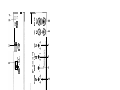
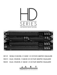
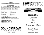
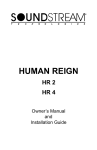
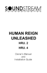
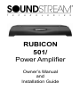
RUBICON
501/
Power Amplifier
Owner’s Manual
and
Installation Guide
1
Congratulations!
You now own the Soundstream RUBICON amplifier, the product of an uncompromising design and engineering philosophy. Your Soundstream
RUBICON amplifier will outperform any other amplifier in the world.
To maximize the performance of your system, we recommend that you thoroughly acquaint yourself with its capabilities and features. Please retain this
manual and your sales receipt for future reference.
Soundstream amplifiers are the result of American innovation and the highest quality control standards. When properly installed, they will provide you
with many years of listening pleasure. Should your amplifier ever need service or replacement due to theft, please record the following information which
will help protect your investment.
Model and Serial #
Dealer’s Name
Date of Purchase
Installation Shop
Installation Date
CAUTION!
Prolonged listening at high levels may result in hearing loss.
Even though your new Soundstream Rubicon amplifier sounds
better than anything you’ve ever heard, exercise caution to
prevent hearing damage.
2
Table of Contents
Design Features ............................................................. p 4 - 5
Rubicon Amplifier Diagram ............................................. p 6 - 7
Crossover and Phase Adjustments ................................ p 8
Hawkins Bass Control™ Theory and Use ...................... p 9 - 10
Installation: Wiring, Diagram, and BIO Port .................... p 11 - 12
Installation: Mounting ..................................................... p 13
Installation: Level Setting and Front Spoiler .................... p 14
Protection Circuitry and Troubleshooting: ...................... p 15
Service and Specifications ............................................. p 16
3
DESIGN FEATURES
¨¨
SLA/SH™ ( Speaker Load Adapting / Subwoofer Hyper-Efficient) This
new dual function technology currently operates in two different ways in
different models. In subwoofer applications the power supply tracks the
incoming audio signal and increases or decreases its own voltage level
to mirror the input. This design results in enormous low impedance, low
frequency stability and maximum efficiency, since no power is wasted
maintaining an unnecessarily high voltage level in the power supply.
¨
BIO™ Port (Bridging In and Out) Enables two identical mono amplifers
channels to be fused together into a single subwoofer load with double
the output power.
¨
STACT™ (STabilized Apex Current Topology) Reduces power supply
stress by 50%. Typical designs degrade the stereo image due to phase
reversal of even-order harmonic distortion that occurs between the inverted channels. In the STACT design, inversion is done at the power
amplifier drive stage. Since the fully symmetrical power amplifier produces no even-harmonic distortion itself and all preamplifier circuitry is
run completely in-phase, no even harmonic distortion phase reversal
occurs.
¨
Trident™ Protection Topology provides three types of protection:
1. Output protection against short circuits or improper loads.
2. Ground fault detection: Shuts down the amplifier when a significant
voltage (> 5Volts) fluctuation occurs between electrical (turn-on lead)
and battery ground.
3. Thermal Protection: Puts the amplifier into thermal rollback or shuts
the amplifier down in extreme thermal conditions.
¨
Hawkins Bass Control - Fully adjustable subwoofer equalizaton circuit
providing frequency and boost (“Q”) adjustment for optimum subwoofer
performance. A frequency tracking subsonic filter protects woofers from
potentially harmfull low frequency information and maximizes output in
a usable range.
¨
Harmonic Bass Alignment™ The 2nd and 3rd order harmonic peaks
are critically aligned to fundamental peaks at low frequencies. This
produces tighter, more accurate bass reproduction.
¨
Drive Delay II™ Amplifier section powers up 2 to 3 seconds after the
power supply eliminating turn-on and off pops. The turn off process is
reversed: Amplifier section turns off first, followed by the power supply.
4
¨
Output Clipping Indicator indicates clipping on the output stage of
the amplifier. Monitoring the clipping indicators allows the user to achieve
maximum Sound Pressure Level without clipping the amplifier.
¨
Dynamically Optimized Power Grid™ Power grid is evenly distributed between primary and secondary power supplies, providing greater
dynamics and improved RF filtering.
¨
Chassisink™ All transistors are ideally located and sandwiched between the circuit board and the heatsink to provide cool efficient amplifier operation.
¨
Differentially Balanced RCA Input eliminates ground loop related
noise in the audio.
¨
Continuously Variable Crossover Network: 24 dB/Octave lowpass
crossover variable from 40 to 160 Hz.
¨
Flexible Input Level Control allows 200 mV to 5 V input sensitivity.
¨
Symmetrical Discrete Balanced Class A Drive Boards auto-adjust
for linear performance while driving low impedance loads.
¨
Removable Front Spoiler allows for stealth installation of RCA, Balanced Line, Speaker and Power wiring.
5
FUSES
1 SOUNDSTREAM
GND
- +
f-----l
REMOTE
2
+12v
LP
XaOVER
dB
HAWKINS 1
FREQ
BOOST
r
l
SUB _ HAWKINS
BASS
CONTROL
SONIC
Iv
LEVEL
PHASE
00~1800
i
1
INPUT
0
Sol/ IN
810 PORT
-R
0
I
I
+l
CUP
KEY TO CALLOUTS
1.
2.
3.
4.
5.
6.
7.
8.
9.
10.
11.
12.
13.
14.
15.
Power LED - Indicates amplifier power, either in High Power or Auto High
Current.
Clip Indicators - Indicates the signal output level is too high and the output
stage of the amplifier is clipping.
Phase Selector - Select between 0 or 180 degrees of output on speaker
terminals.
Subsonic/Hawkins Bass Control Switch - Selectable subwoofer
enhancement circuit. Select “SUB SONIC” to engage the Sub Sonic filter
with no boost. Use the knob indicated by callout #9 to set the frequency: 1330Hz. Select “Hawkins Bass Control” to engage the Sub Sonic filter with
available boost. Use the knob indicated by callout #9 to set the frequency:
30 Hz to 70 Hz.
BIO Port - RCA input and output connections for bridging two identical amplifiers. In BIO mode connect between the master amplifier’s 501/OUT to
the slave amplifier’s 501/IN. This will bridge the amplifiers and bypass the
preamplifier controls on the slave amplifier.
RCA Inputs - Right and Left channel RCA inputs.
Input Level - Input level control variable from 200 mV to 5 V.
Hawkins Bass Control “Boost” Adjustment - Varies from 0 to +9 dB of
boost when the Hawkins Bass Control circuit is engaged.
Subsonic/Hawkins Bass Control Adjustment - Frequency adjustment control for the Hawkins Bass Control filter or the Sub Sonic filter.
Low Pass Filter Control Adjustment - Frequency adjustment control for the
Low Pass filter.
Speaker Connection Terminal - Speaker connections for mono channel.
REMOTE - Remote turn-on input from the head unit. Accepts +12V.
GND - Main ground connection. Bolt to a clean chassis point in the vehicle.
+12V - Connected to a fuse or circuit breaker, then to the battery’s positive
terminal.
FUSE - Main power supply fuse. Warning: Replace only with the same value
fuses!
7
CROSSOVER & PHASE ADJUSTMENTS
The RUBICON amplifiers incorporate an on-board staggered electronic crossover. No external electronic crossover is necessary. The low pass portion of
the crossover can be set independently of the rest of the system.
In many car audio installations, there is a tendency for a “midbass boom.”
Because of their interior dimensions, most cars will resonate or ring at these
midbass frequencies. If we design the system so there is reduced output in
this region, the final response is very smooth and natural sounding. The
Rubicon501/ has an always on low pass crossover that is independently
variable from 40 to 160 Hz at 24 dB/Octave.
For initial crossover setup, try setting the low pass filter to approximately 60
Hz, and the high
pass filter on the
rest of the sytem
12 dB/Octave High Pass
to approximately
100 Hz. Change
the crossover
points to accom24 dB/Octave Low Pass
modate a good mixture of frequency
response, power
handling, and personal preference.
Phase Switch
In many car audio systems placement of the subwoofers can cause them
to be out of phase with the rest of the system. This may cause poor
subwoofer performance due to varying arrival times. To eliminate this the
Rubicon501/ incorporates a 0 to 180 phase switch. By playing low
frequency music and experimenting with the subwoofer phasing better
sound quality and bass imaging may be obtained.
8
Hawkins Bass Control - Theory and Use
SUB . HAWKINS
SONIC
BASS
CONTROL
PHASE
CP*1800
HAWKINS 1
FREQ
BOOST
r
X*OVER
LP
HZ
HAWKINS 30-70 Hz
4 SUBSONIC 1 J-30 Hz
Hawkins Bass Control (parametric) is a unique
subwoofer control circuit included with the
Soundstream RUBICON501/ amplifier. It is capable of removing subsonic energy in program
material while boosting subwoofer frequencies.
The circuit consists of two controls. One adjusts
the frequency of operation and the other adjusts
the range of boost. With both controls adjusted
fully counter-clockwise, no boost is applied and
the amplifier is flat in response down to 20 Hz.
FIG.BASS CONTROL
quency control (Hz) adjusts the
5
starting point of the subsonic filter.
o
On the RUBICON501/ the high pass dB -5
filter has two frequency ranges.
When the bass control switch is set
to “SUB SONIC”, the high pass filter
frequency can be adjusted from 13
Hz up to a maximum of 30 Hz. In
,.
this setting, no boost “Q” control is
available. This control is useful for
5
0
setting the lowest frequency that your
subwoofer will see (see figure 1). dB 3
When the bass control switch is set 1::
to “HAWKINS BASS CONTROL”, the -20
high pass filter frequency can be ad- -25
justed from 30 Hz to a maximum of -301
70 Hz. In this setting, there is an
available boost control of 0 to +9 dB.
FIG. 2 VARIABLE “Q”
FIG. 3 VARIABLE HIGH PASS
The Boost control adjusts the amount
of level applied at the set frequency.
This is adjustable from flat (OdB) to +9
dB. (See figure 2)
-5
dB
-10
FIG. 4 VARIABLE BOOST
When the Boost is set to 0, Hawkins
acts as a sub-sonic filter only. (See
figure 3) The simple act of removing
potentially harmful low frequencies can
improve system output by as much as
3 dB. (see figure 4)
9
Application
Subwoofer drivers in general have
excellent power handling characteristics over their operational bandwidth. This bandwidth is determined
by many factors, including driver design, and enclosure type. It is possible to overdrive any subwoofer
FIG. 5 LIMITED EXCURSION
driver by sending powerful signals
outside of its operational bandwidth. These potentially damaging signals
can be removed by adding a subsonic filter. Figure 5 shows the effectiveness of the Hawkins Bass Control on woofer excursion in a vented enclosure. The woofer travels 7.5 mm at 10 Hz. With Hawkins Bass Control
properly adjusted, this excursion can be reduced to less than 1 mm. This is
of great benefit to lowering woofer distortion and increasing output.
Adjustment
An easy method of optimizing your existing subwoofer enclosure with
Hawkin’s “Hz” control is as follows.
1. Adjust frequency and boost control to full CCW position.
2. Set the bass control switch to “HAWKINS BASS CONTROL”.
3. While listening to music with strong bass content at a moderate level,
slowly adjust frequency control clockwise. Listen for a reduction of bass
response. Now, rotate frequency control slightly backwards. This serves
the purpose of removing the “subsonic” bass energy.
With Soundstream’s Hawkins Bass
Control, the boost and frequency control can provide virtually any combination of boost and cut to suit your designs. So, Hawkins Bass Control can
provide the “tailoring” needed for any
type of “assisted” design and any
woofer in any type of installation.
FIG. 6 VARIOUS SETTINGS
10
(
INSTALLATION STEP 1
WIRING
POWER AND GROUND
To ensure maximum output from your RUBICON amplifier, use high quality, lowloss power and ground cables and connections. The RUBICON amplifiers will
accept up to 4 gauge power and ground cables. Determine from the chart below
the minimum gauge power and ground wire for your application.
up to 70’
RUB/CON 507/ 1
up to 20’
4 or 8 gauge
I
4 gauge only
CIRCUIT BREAKERS AND FUSES
EXTERNAL
Like all audio components, the RUBICON amplifiers must be fused near the
batters. A fuse or circuit breaker must be located within 18” of the batterv. This will
prevent a fire in the event of a shorted cable. See the chart below to determine the
correct fuse value.
e
*
INTERNAL
The RUBICON amplifiers are fused with an automotive-type or Maxi-fuse. In the
event of a blown power supply fuse(s), replace with the correct value fuse found in
the chart below. Never replace the fuse with a higher value than what is supplied. This may result in amplifier damage and will void the warranty!
RUB/CON Amplifier Fuse Values
Battery Fuse / Circuit
Breaker
Amplifier Fuse
1 RUB/CON 507/ 1
(2) 30 amp automotive
11
I
80 amp
I
REMOTE TURN-ON
Connect the “Remote” line to the turn-on lead from the source unit. When +I2
Volts is received, the amplifier will turn on.
SIGNAL CABLE
Use a high quality cable that will be easy to install and has minimal signal loss to
guarantee optimum performance.
SPEAKER CABLE
The RUBICON amplifiers will accept up to 8 gauge speaker cable. Use a high
quality, flexible, multi-strand cable for best performance and longevity.
SAMPLE WIRING DIAGRAM
rI
1
FUSES
+12v
GND
REMOTE
-
+
X-OVER
r HAwKlNs
FREQ
1
BOOST
LEVEL
INPUT
1
1110 PORT
To Chmds
TO+lfB
ToRemde
I
Turn-on
,
f-
1 Head Unit 1
r
B/O Port Bridging Option
The RubiconSOl/ amplifier has the ability to be bridged to another identical
amplifier for double the output by using the BIO Port. When this feature is
used, the master amplifier’s level and crossover switches affect both amplifiers
(the slave amplifier’s controls are totally bypassed). By switching the phase
switch to 180 on the slave amplifier and connecting a RCA cable from the 501/
OUT on the master amplifier to the 5011lN on the slave amplifier both amplifiers
are synchronized. Then connect a positive speaker cable to the master
amplifier’s positive speaker terminal and the other speaker cable to the slave
i n a l l terminal.
y c o n n e c t t h e s p e a k e r wires to a single load
amplifier’s F
positive
no less than 2 ohms. This will supply twice the power of a single amplifier.
12
INSTALLATION STEP 2
INSTALLATION AND MOUNTING
AMPLIFIER LOCATION
The RUBICON amplifiers employ highly efficient circuitry, a custom-engineered
heat sink, and a unique Chassisink construction to maintain lower operating
temperatures. Additional cooling may be required if the amplifier is located in a
tightly confined area or when driving especially low impedance loads at extremely
high levels.
When mounting the amplifier, it should be securely mounted to either a panel in
the vehicle or an amp board or rack that is securely mounted to the vehicle. The
mounting location should be either in the passenger compartment or in the trunk
of the vehicle, away from moisture, stray or moving objects, and major electrical
components. To provide adequate ventilation, mount the amplifier so that there
are at least two inches of freely circulating air above and to the sides of it.
MOUNTING THE AMPLIFIER
a.
b.
c.
Using the amplifier as a template, mark the holes on the mounting surface.
Remove the amplifier and drill the holes for the mounting screws.
Secure the amplifier to the mounting surface using the supplied hardware.
WIRING
a.
b.
c.
d.
e.
f.
Run and connect the audio signal and remote turn-on cables to the amplifier from the source unit.
Carefully run the positive cable from the amplifier to a fuse or circuit breaker
within 18” of the battery.
Connect the fuse or circuit breaker lead to the battery. Leave the circuit
breaker off or the fuse out until everything is bolted down.
Secure the ground cable to a solid chassis ground on the vehicle. It may be
necessary to sand paint down to raw metal for a good connection.
Double check each and every connection!
Re-connect the fuse or circuit breaker.
POWER UP
Power up the system, there may be a 2-3 second delay from the time the source
unit is turned on to the time that the amplifier turns on, which is normal. Once the
amplifier LED is on and the source unit is playing, you should have sound coming
from the speakers.
13
INSTALLATION STEP 3
LEVEL SETTING
The input level is adjusted by means of the input level control located on the front
of the amplifier. This is a unique dual-stage circuit that adjusts both level and
gain. This topology maintains better S/N Ratio even when using sources with
minimal output.
In the ideal situation, all components in the audio system reach maximum
undistorted output at the same time. If you send a distorted signal to an amplifier,
it is simply going to amplify distorted information. The same holds true if an
outboard processor or crossover begins to distort before you have maximum
output from the amplifier. By setting all components to reach clipping at the same
time, you can maximize the output of your system. For the RUBICON amplifiers,
follow these steps for setting the input levels:
1.
2.
3.
Turn the amplifier’s input levels to minimum position (counter-clockwise).
Set the source unit volume to approximately 3/4 of full volume.
While playing dynamic source material, slowly increase the amplifier’s input
level until a near maximum undistorted level is heard in the system.
The clipping indicators on the top of the amplifier let you know when the output of
the amplifier is reaching its maximum level, and has begun to clip.
FRONT SPOILER
Once the amplifier is installed and the proper levels set, place the front spoiler in
position, and secure it on using the supplied hardware.
14
TRIDENT PROTECTION CIRCUITRY
Your Rubicon amplifier is protected against both overheating and short circuits
by means of main power fuses and the following circuits:
+
Speaker Output Protection
+
Ground Fault Differential
+
Smart Power Supply Thermal Rollback & a Thermal Protection Circuit
NOTE: If you experience blown main power supply fuses, if is like$
that the amplifier is seeing a dead short, either in the speaker wire or in
the speaker itself. Rectify the problem before b/owing mu/tip/e fuses!
DO NOT increase values beyond the original fuse value! Doing so will
void your warrant and may damage your amplifer.
TROUBLESHOOTING
CAUSE
PROBLEM
No Sound and power LED is not
lit
1. No power or ground at the
amp.
2. No remote turn-on signal
3. Blown fuse near the battery
No sound, power LED is lit.
1. No signal input
2. The AIRBASSkcessory
switch is in the “IN” position.
Move it to the “OUT’ position.
Repeatedly blow amp fuse;
frequent activation of Smart
Power Supply Circuit
1. Speaker or leads may be
shorted
2. Verify adequate amp
ventilation
“Clip” indicator lighting
Output signal level is too high and
the amplifier output is clipping.
Reduce the level either at the
source or at the input level
controls.
15
SERVICE
Your Soundstream RUBICON amplifier is protected by a limited warranty.
Please read the enclosed warranty card for details.
SPECIFICATIONS
1 SZMono
4SZMono
2MMono
(4 CI BIO Bridged) (2 a BIO Bridged) (1 C2 BIO Bridged)
(12.6 Vdc)
(14.4 Vdc)
(14.4 Vdc)
POWER
I
5011
I
2ooWxl
(800W x 1)
THD
Signal to Noise
Frequency Response
Damping
Input Sensitivity
Input Impedance
4oow x 1
5oow x 1
(1ooowx1)
W)
Maximum
Rated
Output
500 wtts
co. 1%
>90 dB
20 Hz k 0.5 dB to 160 Hz 2 3 dB
>200
200 mV to 5.0 Volts
10k Ohms
Crossover Specifications
Low Pass: 40 Hz - 160 Hz at 24 dB/Octave
Hawkins Bass Control
Sub Sonic Filter: No boost, High Pass filter from 13 to 30 Hz.
Hawkins Bass Control: 0 to +9 dB Boost; Boost and Sub Sonic filter,
variable from 30 to 70 Hz.
Dimensions (W x D x H)
RUBICON50lI: 8.5” X 9.8” X 2.25”
SOUNDSTREAM”
1
E
C
H
N
L
0
0
G
I
SOUNDSTREAM TECHNOLOGIES
11365 Sunrise Park Dr - Ranch0 Cordova - California 95742 USA
ph 916.351 .I288 - fax 916.351.0414
rev A - 9/2MXl
16
E
S