1
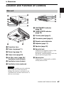
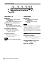
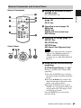
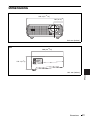
4-198-889-13 (1)
Data
Projector
Operating Instructions
Before operating the unit, please read this manual and supplied Quick Reference Manual
thoroughly and retain it for future reference.
VPL-EX175/EX145/EX120/EX100
Not all models are available in all countries and area. Please check
with your local Sony Authorized Dealer.
© 2010 Sony Corporation
Table of Contents
Overview
Network
Location and Function of Controls .... 3
Main unit ...................................... 3
Connector Panel ........................... 4
Remote Commander and Control
Panel .......................................... 5
Using Network Features (VPL-EX145/
EX175 only) ..................................23
Displaying the Control Window of
the Projector with a Web
Browser ...................................23
Confirming the Information
regarding the Projector ............24
Operating the Projector from a
Computer .................................24
Using the e-mail report
Function ...................................24
Preparation
Connecting the Projector ................... 7
Connecting a Computer ................ 7
Connecting a Video equipment .... 8
Connecting an External Monitor and
Audio Equipment ...................... 9
Projecting/Adjusting an
Image
Projecting an Image ......................... 10
Adjusting the Projected
image ....................................... 11
Turning Off the Power ................ 13
Adjustments and Settings
Using a Menu
Using a MENU ................................ 14
The Picture Menu ............................. 15
The Screen Menu ............................. 16
The Function Menu .......................... 18
The Operation Menu ........................ 19
The Connection/Power Menu .......... 20
The Installation Menu ...................... 21
The Information Menu ..................... 22
2
Table of Contents
Others
Indicators ..........................................26
Messages List ...................................27
Troubleshooting ................................28
Replacing the Lamp ..........................30
Cleaning the Air Filter ......................32
Specifications ...................................33
Projection Distance ...........................38
Dimensions .......................................41
Index .................................................43
B Overview
Location and Function of Controls
Main unit
2
7
8
9
qd
Overview
1
q;
qa
6
qh
qg
qd
qf
qs
qd
3
h ON/STANDBY indicator
(page 26)
i LAMP/COVER indicator
(page 26)
j Control panel (page 5)
k Connector panel (page 4)
l Remote control detector
5
4
m Adjuster (page 11)
a Projection lens
n Speaker (page 18)
b Focus ring (page 11)
o Security lock
c Zoom ring (page 11)
d Lamp cover (page 30)
e Air filter cover (page 32)/
Ventilation holes (intake)
f Ventilation holes (intake)
Connects to an optional security cable
manufactured by Kensington.
For details, visit Kensington’s web site.
http://www.kensington.com/
p Security bar
Connects to a commercially available
security chain or wire.
g Ventilation holes (exhaust)
Caution
Do not place anything near the ventilation
holes as this may cause internal heat
buildup. Do not place your hand near the
ventilation holes and the circumference as
this may cause injury.
Location and Function of Controls
3
Connector Panel
3
1
2
5
7 6
4
8
Input (pages 7, 8)
Output (page 9)
a INPUT A
e OUTPUT
Video: RGB/YPBPR input connector
(RGB/YPBPR)
Audio: Audio input connector (AUDIO)
b INPUT B (VPL-EX120/EX145/
EX175 only)
Video: RGB input connector (RGB)
Audio: Audio input connector (AUDIO)
c S VIDEO (S VIDEO IN)
Video: S video input connector
Audio: Audio input connector (L
[MONO] AUDIO/R)
d VIDEO (VIDEO IN)
Video: Video input connector
Audio: Audio input connector (L
[MONO] AUDIO/R)
Note
The audio inputs of S VIDEO and VIDEO are
shared.
Video: Monitor output connector
(MONITOR)
Audio: Audio output connector
(AUDIO)
Note
This connector outputs the projected image or
audio. The image is output as a computer signal
input from the RGB input connector (INPUT
A/INPUT B (INPUT B is available only for
VPL-EX120/EX145/EX175)) or a video signal
input from the YPBPR input connector (INPUT
A).
Others
f RS-232C connector
RS-232C compatible control connector.
Connects the computer’s RS-232C
connector and the RS-232C cross cables.
g LAN connector (VPL-EX145/
EX175 only) (page 23)
h AC IN (∼) socket
Connects the supplied AC power cord.
4
Location and Function of Controls
Remote Commander and Control Panel
Remote Commander
a Turning on the power/Going to
standby mode
7
INPUT
APA
1
6
ECO MODE
2
MENU
3
c Operating a menu (page 14)
ENTER
ASPECT
KEYSTONE PATTERN
D ZOOM
VOLUME
b Selecting an input signal
(page 10)
INPUT key
RESET
RETURN
4
Overview
4
?/1 (On/Standby) key
PIC MUTING
5
FREEZE AUDIO MUTING
MENU key
RESET key
ENTER /V/v/B/b (arrow) keys
RETURN key
d Adjusting the image (page 11)
ASPECT key
KEYSTONE key
PATTERN key
APA (Auto Pixel Alignment) key*
Control Panel
1 23
3
6
Note
* Use this key when inputting a computer
signal via the RGB input connector
(INPUT A/INPUT B (INPUT B is
available only for VPL-EX120/EX145/
EX175)).
e Using various functions during
projecting
D ZOOM (Digital Zoom) +/– key*1
Enlarges a portion of the image while
projecting.
1 Press the D ZOOM + key to display
the digital zoom icon on the projected
image.
2 Press the V/v/B/b keys to move the
digital zoom icon to the point on the
image you wish to enlarge.
3 Press the D ZOOM + key or the D
ZOOM – key repeatedly to change the
enlargement ratio. The image can be
enlarged up to 4 times.
Press the RESET key to restore the
previous image.
Location and Function of Controls
5
PIC MUTING key
Cuts off the image. Press again to restore
the image.
AUDIO MUTING key
Mutes the audio output. Press again to
restore the previous volume.
VOLUME +/– key
For adjusting the volume output.
FREEZE key*2
Pauses a projected image. Press again to
restore the image.
Notes
*1: Use this key when inputting a
computer signal. But it may not be
used depending on the resolution of
the input signal.
*2: Use this key when inputting a
computer signal.
f Setting the energy–saving mode
easily
ECO MODE key
Energy-saving mode can be set easily.
Energy-saving mode consists of “Lamp
Mode,” “Power Saving Mode” and
“Standby Mode.”
1 Press the ECO MODE key to display
the ECO Mode menu.
ECO Mode Menu
ECO Mode
ECO
User
Sel
Back
2 Press the V/v key or ECO MODE key
to select ECO or User mode.
ECO: Sets each mode to the optimum
energy-saving value.
Lamp Mode: Low
Power Saving Mode: Standby
Standby Mode: Low
(go to step 6)
User: Sets each item of the energysaving mode menu as you desire
(go to step 3).
6
Location and Function of Controls
3 Select “User” then press the b key.
The setting items appear.
User
Lamp Mode
Standard
Power Saving Mode
Off
Standby Mode
Low
Sel
Set
Back
4 Press the V/v key to select the item
then press the ENTER key.
5 Press the V/v key to select the setting
value.
6 Press the ENTER key to restore the
previous image.
For details on ECO Mode settings, see
“Lamp Mode” (page 18) on the Function
menu and “Standby Mode” (page 20)
and “Power Saving Mode” (page 20) on
the Connection/Power menu.
Others
g Infrared transmitter
About Remote Commander operation
• Direct the Remote Commander toward the
remote control detector.
• The shorter the distance between the
Remote Commander and the projector is,
the wider the angle within which the
Remote Commander can control the
projector becomes.
• Make sure that nothing obstructs the
infrared beam between the Remote
Commander and the remote control
detector on the projector.
B Preparation
Connecting the Projector
Notes
• Make sure all the equipment is powered off when connecting the projector.
• Use the proper cables for each connection.
• Insert the cable plugs firmly; Loose connections may reduce performance of picture signals or
cause a malfunction. When pulling out a cable, be sure to grip it by the plug, not the cable itself.
• For more information, refer also to the instruction manuals of the equipment you are connecting.
• Use a no-resistance audio cable.
Preparation
Connecting a Computer
Connection with a computer is explained for each input signal.
INPUT A/INPUT B (INPUT B is available only for VPL-EX120/EX145/EX175)
For connecting a computer with an RGB output connector.
Mini D-sub 15-pin cable (supplied)
RGB output connector
Computer
Audio output connector
Audio cable (Stereo mini plug) (not supplied)
Note
• It is recommended that you set the resolution of your computer to 1024 × 768 pixels for the
external monitor.
Connecting the Projector
7
Connecting a Video equipment
Connections with a VHS video deck, DVD player, or BD player are explained for each input
signal.
S VIDEO IN
For connecting video equipment with an S-video output connector.
S video cable
(not supplied)
Video equipment
S video output
connector
Audio output
connector
Audio cable (Phono plug × 2) (not supplied)
VIDEO IN
For connecting video equipment with a video output connector.
Video cable
(not supplied)
Video equipment
Video output
connector
Audio output
connector
Audio cable (Phono plug × 2) (not supplied)
INPUT A
For connecting video equipment with a YPBPR output connector.
Component – Mini D-sub 15-pin cable (not supplied)
Video equipment
YPBPR output
connector
Audio output
connector
Audio cable (Phono plug × 2 – stereo mini plug) (not supplied)
8
Connecting the Projector
Connecting an External Monitor and Audio Equipment
OUTPUT
Projected images and input audio can be output to display equipment such as a monitor and
audio equipment such as speakers with a built-in amplifier.
Display equipment
RGB input
connector
Mini D-sub 15-pin
cable (supplied)
Preparation
Audio input
connector
Audio equipment
Audio cable
(stereo mini plug)
(not supplied)
Note
Projected images and audio can be output. The image is output only as a computer signal input from
the RGB input connector (INPUT A/INPUT B (INPUT B is available only for VPL-EX120/EX145/
EX175)) or a video signal input from the YPBPR input connector (INPUT A).
Connecting the Projector
9
B Projecting/Adjusting an Image
Projecting an Image
The size of a projected image depends on the distance between the projector and screen. Install
the projector so that the projected image fits the screen size. For details on projection distances
and projected image sizes, see “Projection Distance” (page 38).
5
Input
Video
S-Videoo
Input-A
Input-B
Sel
Skip
3
4
5
6
Computer
2
Video equipment
Projector
1
1
Plug the AC power cord into the wall
outlet.
2
Connect all equipment to the projector
(page 7).
3
Press ?/1 to turn on the unit.
4
Turn on the connected equipment.
5
Select the input source.
Press the INPUT key on the projector to
display the input select window. Press
the INPUT key repeatedly or the V/v
key to select an image to be projected.
10
Projecting an Image
6
Wall outlet
Switch your computer to output to
external display by changing your
computer’s setting.
How to switch the computer to output to
the projector varies, depending on the
type of computer.
(Example)
+
7
Adjust the focus, size, and position of
the projected image (page 11).
Adjusting the Projected image
Focus
Size (Zoom)
Position
Projecting/Adjusting an Image
Adjuster adjustment button
Adjusting the tilt of the projector with the adjusters
You can adjust the height of the projector
using the adjusters.
By changing the slope of the projector with
adjusters, you can adjust the position of the
projected image.
Notes
• Be careful not to let the projector down on your fingers.
• Do not push hard on the top of the projector with the adjuster extended. It may cause malfunction.
Projecting an Image
11
Changing the aspect ratio of the projected image
Press ASPECT on the remote commander to change the aspect ratio of the projected image.
You can also change the setting in Aspect of The Screen Menu (page 16, page 17).
Correcting trapezoidal distortion of the projected image (Keystone feature)
Keystone feature may not work automatically when the screen is tilted. In this case, set
keystone manually.
1 Press KEYSTONE on the remote
commander or select V Keystone in The
Installation Menu.
2 Use V/v/B/b to set the value. The higher
the setting, narrower the top of the
projected image. The lower the setting, the
narrower the bottom.
Increase the number
towards plus
Note
Since the Keystone adjustment is an electronic
correction, the image may be deteriorated.
Increase the number
towards minus
Displaying a pattern for adjusting an image
You can display a pattern for adjusting the projected image with the PATTERN key on the
Remote Commander. Press the PATTERN key again to restore the previous image.
Automatically adjusts Phase, Pitch and Shift of projected image while a
signal is input from a computer (APA (Auto Pixel Alignment)).
Press APA on the remote commander. Press again to cancel during the setting. You can also set
APA in The Screen Menu (page 16).
If Smart APA is set to On, executes APA automatically when a signal is input (page 18).
12
Projecting an Image
Turning Off the Power
1
Press the ?/1 key on the main unit or the Remote Commander.
The message appears. Press it again according to the message.
2
Unplug the AC power cord from the wall outlet.
After step 1, the fan continues to run for a while to reduce internal heat, however, you may
also unplug the AC power cord before the fan stops.
To clear the confirmation message
The message disappears if you press any key other than the ?/1 key on the main unit or the
Remote Commander, or if you do not press any key for a while.
To turn off without displaying confirmation message
Hold the ?/1 key on the main unit or the Remote Commander pressed for a few seconds.
Projecting/Adjusting an Image
Projecting an Image
13
B Adjustments and Settings Using a Menu
Using a MENU
Note
The menu displays used for the explanation below may be different depending on the model you are
using.
1
Press the MENU key to display the
menu.
value of an item to its factory preset
value, press the RESET key during
setting or adjusting.
2
Select the setting menu.
Use the V or v key to select the setting
menu then press b or ENTER key.
Using a pop-up menu
Press the V/v/B/b key to select an item.
Press the ENTER key to restore the
previous screen.
Setting menu
Selecting items
Picture
Picture Mode
Reset
Contrast
Brightness
Color
Hue
Color Temp.
Sharpness
Expert Setting
Sel
Function
Standard
Volume
Speaker
Smart APA
CC Display
Lamp Mode
Lamp Timer Reset
Background
Start Up Image
80
50
50
50
Middle
50
Set
To return to the selection screen of the
setting menu, press the B key or the
RETURN key.
Dynamic
Standard
Presentation
Living
Game
Cinema
Picture
Sel
Set
Back
Picture Mode
Setting items
Picture Mode
Reset
Contrast
Brightness
Color
Hue
Color Temp.
Sharpness
Expert Setting
Set
Using the setting menu
Press the V or v key to select the item.
Press the ENTER key to restore the
previous screen.
Select the setting item.
Use the V or v key to select the setting
menu then press b or ENTER key.
Sel
Blue
On
Back
Sel
3
30
On
On
Standard
Off
Standard
Back
Standard
Using the adjustment menu
To increase the number, press the V or b
key and to decrease the number, press
the v or B key. Press the ENTER key to
register the setting. The previous screen
is restored.
80
50
50
50
Middle
50
Back
Contrast
4
Make the setting or adjustment for the
selected item.
Menu operation differs depending on the
setting item. If the next menu window is
displayed, select the item according to
the operations in step 3.
To return to the selection screen of the
setting items, press the B key or the
RETURN key. Also, to reset the setting
14
Using a MENU
Min
Max
80
Adjust
5
Back
Press the MENU key to clear the
menu.
The menu disappears automatically if no
key is pressed for a while.
The Picture Menu
For adjusting the picture for each input signal.
Item descriptions
Picture Mode
Dynamic: Emphasizes the contrast to produce a “dynamic and vivid” picture.
Standard: Makes the picture be natural and well balanced.
Presentation*1: Makes the picture bright to suit for a presentation.
Living: Select for viewing sports, music, and digital video camera picture.
Game: Select for viewing game picture.
Cinema: Select for viewing film-like picture.
Reset*2
The picture settings are initialized to their factory preset values.
Contrast
The higher the setting, the greater the contrast. The lower the setting, the lower
the contrast.
Brightness
The higher the setting, the brighter the picture. The lower the setting, the darker
the picture.
Color*3 *5
The higher the setting, the greater the intensity. The lower the setting, the lower
the intensity.
Hue*3 *5 *6
The higher the setting, the more greenish the picture becomes. The lower the
setting, the more reddish the picture becomes.
Color Temp.*4
High/Middle/Low: The higher the temperature, the more bluish the picture.
The lower the temperature, the more reddish the picture.
Sharpness*3
The higher the setting, the sharper the picture. The lower the setting, the softer
the picture.
Expert Setting
Film
Mode*3 *7
Auto: Precisely reproduces the image from a film source to suit the original
film source. Normally, select this option.
Off: Select this option if the images are rough around the edges when “Auto” is
selected.
Gamma
Mode*1
Graphics: Improves the reproduction of halftones. Photos can be reproduced
in natural tones.
Text: Contrasts black and white. Suitable for images that contain lots of text.
Notes
*1:
*2:
*3:
*4:
*5:
*6:
*7:
Adjustments and Settings Using a Menu
Items
When a computer signal is input, this option is available.
Picture Mode setting will not be initialized to the factory preset value.
When a video signal is input, this option is available.
When “Picture Mode” is set to the item other than “Presentation,” this option is available.
When a B & W signal is input, this option is not available.
When an analog TV signal is input, this option may not available, depending on the color system.
When a progressive signal is input, this option is not available.
The Picture Menu
15
The Screen Menu
For adjusting the size, position, and aspect ratio of the projected image for each input signal.
Items
Item descriptions
*1
Changes the aspect ratio of the projected image. (page 17).
When the
computer
signal is
input
Normal: Displays the image on the center point of the projected image
without changing the resolution of the input signal or enlarging the image.
Aspect
Full1: Displays the image to fit the maximum projected image size without
changing the aspect ratio of the input signal.
Full2: Displays the image to fit the maximum projected image size.
4:3: Displays the image to fit the maximum projected image size with an
When the
video signal aspect ratio fixed to 4:3.
16:9: Displays the image to fit the maximum projected image size with an
is input
aspect ratio fixed to 16:9.
Zoom: Display the center point of the projected image to zoom.
Adjust Signal
Adjusts the image of signal. Use this item if the edge of the image is cut and
reception is bad.
APA*2 *3
Automatically adjusts the projected image to an optimum quality when you
press the ENTER key.
Phase*2
Adjusts the dot phase of the display pixel and the input signal. Set to the
value where looks clearest.
Pitch*2
The higher the setting, the wider the horizontal image elements (pitch). The
lower the setting, the narrower the horizontal image elements (pitch).
Shift*4
H: The higher the setting, the farther right the image is projected on the
screen. The lower the setting, the image farther left.
V: The higher the setting, the farther up the image is projected on the screen.
The lower the setting, the image farther down.
Notes
*1: • Note that if the projector is used for profit or for public viewing, modifying the original picture
by switching to the aspect mode may constitute an infringement of the rights of authors or
producers, which are legally protected.
• Depending on the input signal, setting items for aspect ratio or some other setting items cannot
be set in some cases, or changing the aspect ratio setting may have no effect.
• A part of the image may be displayed in black, depending on the setting item.
*2: Available when a computer signal is input from the RGB input connector (INPUT A/INPUT B
(INPUT B is available only for VPL-EX120/EX145/EX175)).
*3: If the projected image includes large amount of black portion around it, the APA function will
not work properly and a part of the image may not be displayed on the screen and also optimum
image cannot be obtained, depending on the type of input signal. In this case, adjust the “Phase,”
“Pitch,” and “Shift” items manually.
*4: Available when a computer signal is input from the RGB input connector (INPUT A/INPUT B
(INPUT B is available only for VPL-EX120/EX145/EX175)) or a video signal is input from the
YPBPR input connector (INPUT A).
16
The Screen Menu
Input signal
Recommended
setting value and
projected image
(4:3)
(Full1)*1
*1 *2
(16:9)
(Full1)
(16:10)
(Full1)*1 *2
(4:3)
(4:3)*3
*1: If you select “Normal,” the image is
projected in the same resolution as the
input signal without changing the aspect
ratio of the original image.
*2: If you select “Full2,” the image is projected
to fit the projected image size, regardless
of the aspect ratio of the image.
*3: Depending on the input signal, the
projected image may be projected as
illustrated below. In this a case, select
“16:9.”
*4: Depending on the input signal, the image
may be projected as illustrated below. In
this a case, select “Zoom.”
(16:9)
(16:9)*4
The Screen Menu
Adjustments and Settings Using a Menu
Video signal
Computer signal
Aspect
17
The Function Menu
The Function menu is used for setting various functions of the projector.
Items
Item descriptions
Volume
The higher the setting, the higher an audio volume and the lower the
setting, the lower the audio volume. The audio output level will work
simultaneously.
Speaker
On/Off: When set to “On,” the sound will be output from the speaker. Set
“Off” to mute the sound.
Smart APA
On/Off; When set to “On,” executes APA automatically when a signal is
input.*1
CC Display
CC1/CC2/CC3/CC4/Text1/Text2/Text3/Text4: Select the closed
caption service (Captions or Text).
Off: Closed caption does not appear.
Lamp Mode
High/Standard/Low: When set to “High,” the image becomes brighter,
and power consumption becomes higher.
Lamp Timer Reset
When replacing the lamp, resets the lamp timer (page 30).
Background
Black/Blue: Selects the background color of the projected image when no
signal is input.
Start Up Image
On/Off: When set to “On,” the Start Up Image is displayed on the screen
upon startup of the projector.
Note
*1: Executes APA when a computer signal is input via the RGB input connector (INPUT A/INPUT
B (INPUT B is available only for VPL-EX120/EX145/EX175)).
18
The Function Menu
The Operation Menu
The Operation Menu is used for setting for the operations by using the menu or the Remote
Commander.
Item descriptions
Language
Selects the language used in the menu and on-screen displays.
Status
On: All on-screen statuses are enabled.
Off: Turn off the on-screen displays except for the menus, message when
turning off the power, and warning messages.
Security Lock*1
On/Off: This function enables restriction of the projector to authorized users
by password. The setting procedures for security locking are as follows:
1 Select “On” and press ENTER to display the setting menu.
2 Input the password with the MENU, V/v/B/b, and ENTER keys. (The
default password setting is “ENTER, ENTER, ENTER, ENTER.”)
3 Input a new password with the MENU, V/v/B/b, and ENTER keys.
4 Enter the password again to confirm.
Enter the password when you turn on the projector after disconnecting and
reconnecting the AC power cord.
When it is set to “Off,” you can cancel the security lock. You are required to
input the password again.
If you fail to enter the correct password after three consecutive times, the
projector cannot be used. In this case, press the ?/1 key to go Standby mode
then turn on the power again.
Panel Key Lock
On/Off: When set to “On,” locks all the control panel keys of the projector.
However, you can operate the following when set to “On”:
• Press and hold the ?/1 key for approximately 10 seconds during Standby
mode.
c The projector turns on.
• Press and hold the MENU key for approximately 10 seconds during power
on.
c “Panel Key Lock” is set to “Off” and enables operation of all keys on the
projector.
Note
*1: You will not be able to use the projector if you forget your password. If you call qualified Sony
personnel because you have forgotten the password, you will be asked to verify the projector’s
serial number and your identity. (This process may differ in other countries/regions.) Once your
identity has been confirmed, we will provide you with the password.
The Operation Menu
Adjustments and Settings Using a Menu
Items
19
The Connection/Power Menu
The Connection/Power menu is used for setting for the connections and power.
Items
Item descriptions
Network Setting*3
IP Address Setup
Auto (DHCP): The IP address is assigned automatically from the
DHCP server such as a router.
Manual: To specify the IP Address manually.
IP Address/ Subnet
Mask/ Default
Gateway/Primary
DNS/Secondary
DNS
When “Manual” is selected for “IP Address Setup,” select the item
with the B or b key and input the value with V or v key. When all
items are entered, select “Apply” then press the ENTER key. The
entered settings will be registered.
Input-A Signal Sel.
Auto/Computer/Video GBR/Component: When set to “Auto,”
selects the type of video signal input automatically when “Input-A” is
selected with the INPUT key.*1
Color System
Auto/NTSC3.58/PAL/SECAM/NTSC4.43/PAL-M/PAL-N: When set
to “Auto,” selects the color system automatically when “S Video” or
“Video” is selected with the INPUT key.*1
Standby Mode*2
Standard/Low: When set to “Low,” lowers power consumption in
Standby mode.
Power Saving Mode
Lamp Cutoff: The lamp turns off automatically and power
consumption is reduced if no signal is input for 10 minutes. The lamp
lights again when a signal is input or any key is pressed. In Lamp
Cutoff, the ON/STANDBY indicator lights in orange (page 26).
Standby: The power will be turned off automatically and the projector
goes to Standby mode if no signal is input for 10 minutes.
Off: The Power Saving Mode is canceled.
Direct Power On
On/Off: When set to “On,” you can turn the power on without going
to Standby mode when the AC power cord is connected to a wall
outlet. Regardless of the Direct Power On setting, you can disconnect
the AC power cord to turn off the power without going to the Standby
mode.
Notes
*1: The image may not be adjusted properly depending on the type of input signal. In such a case,
adjust it manually to suit to the connected equipment.
*2: When “Standby Mode” is set to “Low,” the network and network control function cannot be
operated while the projector is in standby mode.
*3: VPL-EX145/EX175 only.
20
The Connection/Power Menu
The Installation Menu
The Installation menu is used for installing the projector.
Items
Item descriptions
Image Flip
HV/H/V/Off: Flips the projected image horizontally and/or vertically
according to the installation method.
Installation Attitude
Right Side Up/Upside Down: Change the cooling setting to suit to the
installation attitude. Continuing to use the wrong setting may affect
component reliability.
High Altitude
Mode*2
On/Off: Set to “On” when using the projector at an altitude of 1,500 m or
higher. Continuing to use the wrong setting may affect component
reliability.
V Keystone*1
Auto: Set keystone adjustment automatically. When the projector is
installed on an uneven surface, the feature may not work properly. In this
case, select “Manual” to set keystone adjustment manually.
Manual: The higher the setting, narrower the top of the projected image.
The lower the setting, narrower the bottom of the projected image.
Notes
The Installation Menu
Adjustments and Settings Using a Menu
*1: Since the Keystone adjustment is an electronic correction, the image may be deteriorated.
*2: When “High Altitude Mode” is set to “On,” the speed of the fan increases, and the fan noise
becomes slightly louder.
21
The Information Menu
The Information menu enables you to confirm various information on the projector, such as the
total usage hours of a lamp.
Items
Item descriptions
Model Name
Displays the model name.
Serial No.
Displays the serial number.
fH / fV (horizontal
frequency/vertical
frequency)*1
Displays the horizontal frequency/vertical frequency of the current input
signal.
Signal type
Displays the type of the current input signal.
Lamp Timer
Indicates the total usage time of a lamp.
Note
*1: These items may not be displayed depending on the input signal.
22
The Information Menu
B Network
Using Network Features (VPL-EX145/EX175
only)
Connection to the network allows you to operate the following features:
• Checking the current status of the projector via a Web browser.
• Remotely controlling the projector via a Web browser.
• Receiving the e-mail report for the projector.
• Making the network settings for the projector.
• Supports network monitoring, control protocol (Advertisement, PJ Talk, PJ Link, SNMP,
AMX DDDP [Dynamic Device Discovery Protocol]).
Notes
• The menu displays used for the explanation below may be different depending on the model you
are using.
• Supported Web browsers are Internet Explorer 6/7/8.
• The menu displays only English.
• If the browser of your computer is set to [Use a proxy server] when you have access to the projector
from your computer, click the check mark to set accessing without using a proxy server.
Displaying the Control Window of the Projector with a Web
Browser
1
LAN cable
(straight type)
(not supplied)
LAN Connector
The following window appears in the
Web browser:
Network
(xxx.xxx.xxx.xxx: IP address for the
projector)
You can confirm the IP address of the
projector under “Network Setting” on
the Connection/Power menu.
Connect the LAN cable.
Hub, router, etc
2
3
Set the network settings for the
projector using “Network Setting” on
the Connection/Power menu
(page 20).
Start a web browser on the computer,
enter the following in the address field,
then press the Enter key on your
computer.
http://xxx.xxx.xxx.xxx
Once you make the network settings, you
can open the Control window only by
performing step 3 of this procedure.
Using Network Features (VPL-EX145/EX175 only)
23
How to operate the Control window
Switching the page
Click one of the Page Switching buttons to
display the desired setting page.
Confirming the Information
regarding the Projector
You can confirm the current settings for the
projector on the Information page.
Page Switching buttons
Setting the access limitation
You can limit a user for accessing any
particular page.
Administrator: Allowed access to all
pages
User: Allowed access to all pages except
the Setup page
Set under [Password] of the Setup page.
When you access the Setup page for the first
time, enter “root” for user name and enter
nothing for password.
The name of the administrator is preset to
“root.”
Information area
Operating the Projector from
a Computer
You can control the projector from the
computer on the Control page.
Entry area for [Administrator]
Operation area
Entry area for [User]
When you change the password, input a new
password after deleting the password
(*****) that was set.
Note
If you forget your password, consult with
qualified Sony personnel.
24
The functions of the keys shown in the
operation area are the same as those of the
keys on the supplied Remote Commander.
Using the e-mail report
Function
Set the e-mail report function on the Setup
page.
Entered values will not be applied unless
you click on [Apply].
Using Network Features (VPL-EX145/EX175 only)
1
Click on [Owner information] to enter
the owner information recorded in the e-
3
Enter the outgoing e-mail address in
the Email Address box then check the
Report Timing check box of the e-mail
report to be sent.
4
Set the mail account for sending email reports.
mail report.
Owner information button
2
1
Set the timing of the e-mail report.
Click on [Mail Report] to open the Mail
Report page.
Lamp Reminder (Lamp1): Set the
timing for lamp replacement. To reset
Lamp Reminder, execute “Lamp
Timer Reset” on the projector
(page 18).
Maintenance Reminder: Set the timing
for maintenance. To reset
Maintenance Reminder, check the
RESET check box and then click on
[Apply].
Mail Report button
5
2
Network
Mail Address: Enter the e-mail address.
Outgoing Mail Server (SMTP): Enter
the address of outgoing mail server
(SMTP).
Required Authentication: Check this
check box if authentication is required
for sending e-mail.
Requires the use of POP
Authentication before send email
(POP before SMTP): Check this
check box to arrange for POP
authentication to be performed before
sending e-mail.
Incoming Mail Server (POP3): Enter
the address of the incoming-mail
server (POP3) to be used for POP
authentication.
Account Name: Enter the mail account.
Password: Enter the password.
SMTP Authentication: Check this
check box to arrange for SMTP
authentication to be performed before
sending e-mail.
Account Name: Enter the mail account.
Password: Enter the password.
Confirm the contents of the e-mail
report.
When you click on [View] is pressed, the
contents of the e-mail report are
displayed.
3
4
6
Send the test mail.
Check on the Send test mail check box
then click on [Apply] to send your test
mail to the e-mail address you set.
Notes
6
5
• The e-mail report function is not available
because the network which Outbound Port25
Blocking is used cannot be connected to the
SMTP server.
• You cannot use the following characters to
enter the characters in the text box: “ ' ”, “ “
”, “ \ ”, “ & ”, “ < ”, “ > ”
Using Network Features (VPL-EX145/EX175 only)
25
B Others
Indicators
The indicators allow checking the status and notify you of abnormal operation of the projector.
If the projector exhibits abnormal status, address the problem in accordance with the table
below.
ON/STANDBY indicator
Status
Meaning/Remedies
Lights in red
The projector is in Standby mode.
Flashes in green
• The projector is ready to operate after having been turned on.
• The lamp cools after the projector is turned off.
Lights in green
The projector’s power is on.
Lights in orange
The projector is in Power Saving Mode (lamp cut off). (page 20)
Flashes in red
The projector is in abnormal status. Symptoms are indicated by
number of flashes. Address the problem in accordance with the
following. If the symptom is shown again, consult with qualified Sony
personnel.
Flashes twice
The internal temperature is unusually high. Check the items below.
• Check to see if nothing is blocking the ventilation holes.
• Check to see if the air filter is not clogged.
• Check if “Installation Attitude” on the Installation menu is correctly
selected. (page 3, page 32, page 21)
Flashes six times
Unplug the AC power cord from a wall outlet. After checking that the
ON/STANDBY indicator goes out, plug the power cord to a wall
outlet again then turn on the projector.
Other number of
flashes
Consult with qualified Sony personnel.
LAMP/COVER indicator
Status
Meaning/Remedies
Flashes in red
Symptoms are indicated by number of flashes. Address the problem in
accordance with the following.
Flashes twice
The lamp cover is not attached securely. (page 32)
Flashes three times The temperature of lamp is unusually high. Turn off the power and
wait for lamp to cool then turn on the power again. If the symptom is
shown again, the lamp may be burnt out. In such a case, replace the
lamp with a new one (page 30).
26
Indicators
Messages List
When any of the messages listed below appears on the projected image, address the problem in
accordance with the table below.
Message
Meaning/Remedy
Page
High temp.! Lamp off in Check the items below.
1 min.
• Check to see if nothing is blocking the ventilation holes.
• Check to see if the air filter is not clogged.
• Check if “Installation Attitude” on the Installation menu is
correctly selected.
3, 21,
32
Frequency is out of
range!
Change the output setting of the connected equipment to one
for signals supported by the projector.
37
Please check Input-A
Signal Sel.
Set “Input-A Signal Sel.” to “Auto” or select the input signal
type to suit to the input signal.
20
30, 32
Please replace the Lamp Replace the lamp with a new one and clean the air filter. To
and clean the Filter.
cancel the message, press any key on the Remote Commander
or the control panel of the projector. The message appears
whenever you turn on the power until you replace the lamp and
reset the lamp timer.
Projector temperature is
high. High Altitude
Mode should be “On” if
the projector is being
used at high altitude.
At an altitude of 1,500 m or higher, if you are not using the
projector, check the items below.
• Check that nothing is blocking the ventilation holes.
• Check that the air filter is not clogged.
• Check if “Installation Attitude” on the Installation menu is
correctly selected.
3, 21,
32
Not applicable!
Invalid key pressed.
–
The panel keys are
locked!
“Panel Key Lock” is set to “On.”
19
Others
Messages List
27
Troubleshooting
Before asking to have the projector repaired, try to diagnose the problem, following the
instructions below.
Symptom
Remedy
The power is not turned
on.
Check if the AC power cord is firmly connected.
–
When the “Panel Key Lock” is set to “On,” you cannot turn on
the projector using the ?/1 key on the projector.
19
If the lamp and lamp cover is not attached securely, the
projector cannot be turned on.
30
Check if the connecting cable is connected to external
equipment firmly.
–
Check if the computer signal is set for output to an external
monitor. If you set your computer, such as a notebook
computer, to output the signal to both your computer’s display
and an external monitor, the picture of the external monitor
may not appear properly. Set your computer to output the
signal to only an external monitor.
10
Check if the input source is correctly selected.
10
Check if the picture is muted.
6
On-screen display does
not appear.
The on-screen display does not appear when “Status” in the
Operation menu is set to “Off.”
19
The aspect ratio of the
display is not right/the
image is displayed
smaller /a portion of
image does not appear.
Set “Aspect” manually.
5, 16,
17
The image is a
trapezoid.
The images become trapezoidal because of the projection
angle. In such a case, you can correct the trapezoidal
distortion, using a Keystone feature.
5, 12,
21
When the “V Keystone” is set to “Manual,” the keystone
feature does not work automatically. Set “V Keystone” to
“Auto” or “Manual” to set manually.
5, 12,
21
No image.
Page
5, 12,
When the projector is installed on an uneven surface, the
feature may not work properly. In this case, select “Manual” to 21
set “V Keystone” manually.
The image is dark/too
bright.
The image is not clear.
28
Troubleshooting
The settings for “Brightness,” “Contrast,” and “Lamp Mode”
affect brightness of the image. Check if the value is
appropriate.
15, 18
The image will be dark when the lamp is burnt out. Check
“Lamp Timer,” and replace the lamp with a new one if
necessary.
22
Check if the projector is in focus.
11
The picture will not be clear if condensation has accumulated
on the lens. In such a case, let the projector sit for about two
hours with the power on.
–
Symptom
Remedy
The image is noisy.
Check if the connecting cable is connected to external
equipment properly.
Page
7
No sound.
Check that the connecting cables between the projector and
external video or audio equipment are securely connected.
7
Check if the connecting cable is connected to external
equipment firmly.
–
Audio is not output if audio muting is activated.
6
Audio is not output if “Speaker” is set to “Off.”
18
Check if “Volume” is not set to minimum.
6, 18
The Remote
Commander does not
work.
Check that the batteries are installed correctly.
–
Check that the batteries are not exhausted.
–
The fan is noisy.
The sound from the fan is often greater than normal to cool the 18, 21
lamp, etc. in the following cases.
• “Lamp Mode” is set to “High.”
• “High Altitude Mode” is set to “On.”
• The unit is used in the location where the temperature is high.
If the ventilation holes are blocked, the internal temperature of
the projector rises and the fan noise becomes larger.
3
Others
Troubleshooting
29
Replacing the Lamp
Replace the lamp with a new one if a message displayed on the projected image or the LAMP/
COVER indicator notifies you to replace the lamp (pages 26, 27).
Use an LMP-E211 projector lamp (not supplied) for replacement.
Caution
• The lamp remains hot after the projector is
turned off. If you touch the lamp, you may
burn your finger. When you replace the
lamp, wait for at least an hour after
turning off the projector for the lamp to
cool sufficiently.
• Do not allow any metallic or inflammable
objects into the lamp replacement slot after
removing the lamp, otherwise it may cause
electrical shock or fire. Do not put your
hands into the slot.
1
Turn off the projector, and disconnect
the AC power cord from a wall outlet.
2
When the lamp has cooled
sufficiently, open the lamp cover by
loosening 1 screw.
3
Loosen the 2 screws on the lamp then
pull out the lamp by its grab.
• If the lamp breaks, contact qualified
Sony personnel. Do not replace the lamp
yourself.
• When removing the lamp, be sure to pull it
out straight, by holding the designated
location. If you touch a part of the lamp other
than the designated location, you may be
burned or injured. If you pull out the lamp
while the projector is tilted, the pieces may
scatter if the lamp breaks any may cause
injury.
Grab
30
Replacing the Lamp
4
5
Insert the new lamp all the way in until
it is securely in place. Tighten the
2 screws.
Caution
Disposal of the used lamp
For the customers in the USA
Lamp in this product contains mercury.
Disposal of these materials may be
regulated due to environmental
considerations. For disposal or
recycling information, please contact
your local authorities or the
Telecommunications Industry
Association (www.eiae.org).
Close the lamp cover and tighten the
1 screw.
Note
Be sure to install the lamp and Lamp cover
securely as it was. If not, the projector
cannot be turned on.
Connect the AC power cord to a wall
outlet and turn on the projector.
7
Reset the lamp timer for notification of
Others
6
the next replacement time.
Select “Lamp Timer Reset” on the
Function menu then press the ENTER
key. When a message appears, select
“Yes” to reset the lamp timer (page 18).
Replacing the Lamp
31
Cleaning the Air Filter
When a message appears on the projected image, clean the air filter (page 27).
If the dust cannot be removed from the air filter even after cleaning, replace the air filter with
a new one.
For details on a new air filter, consult with qualified Sony personnel.
Caution
If you neglect to clean the air filter, dust may accumulate, clogging it. As a result, the
temperature may rise inside the unit, leading to a possible malfunction or fire.
1
Turn off the projector, and disconnect
the AC power cord from the AC outlet.
4
2
Draw out the air filter cover.
Be sure to attach the air filter cover firmly.
Incorrect attachment of the cover may cause a
malfunction.
Note
Air filter
3
Clean the air filter with a vacuum
cleaner.
Remove the air filter as illustrated below
then clean with the vacuum cleaner.
Claws
32
Attach the air filter cover to the unit.
Cleaning the Air Filter
Specifications
Item
Description
Model
VPL-EX100/EX120/EX145/EX175
Projection system
Display device
Projection lens
3 LCD system
Effective display
size
0.63-inch (16.0 mm), 3 plate, Aspect ratio 4:3
Effective picture
elements
2,359,296 pixels (1024 × 768 pixels, 3 plate panels)
Zoom
Manual zoom (approx.1.3 times)
Focus
Manual
Light source
High-pressure mercury lamp, 210 W type
Projected image
size
30 inches to 300 inches (0.762 m to 7.62m)
Luminous flux
(Brightness)
VPL-EX100: 2300 lm (when “Lamp Mode” is set to
“High”)
VPL-EX120: 2600 lm (when “Lamp Mode” is set to
“High”)
VPL-EX145: 3100 lm (when “Lamp Mode” is set to
“High”)
VPL-EX175: 3600 lm (when “Lamp Mode” is set to
“High”)
Speaker
VPL-EX100/EX120: 1W × 1 (monaural)
VPL-EX145/EX175: 10W × 1 (monaural)
Applicable
scanning
frequency*1
Horizontal: 14 kHz to 93 kHz, Vertical: 47 Hz to 93 Hz
Resolution
When a computer Maximum display resolution: 1600 × 1200 pixels (resize)
signal is input
Panel display resolution: 1024 × 768 pixels
Color system
INPUT OUTPUT
(Computer/video)
NTSC, PAL, SECAM, 480/60i, 576/50i, 480/60p,
576/50p, 720/60p, 720/50p, 1080/60i, 1080/50i
NTSC3.58, PAL, SECAM, NTSC4.43, PAL-M, PAL-N,
PAL60
INPUT A
RGB/YPBPR input connector: Mini D-sub 15 pin
female, G with sync/Y: 1 Vp-p ± 2 dB, sync negative, 75
ohms terminated, RGB/PBPR: 0.7 Vp-p ± 2 dB, 75 ohms
terminated, Sync signal: TTL level high impedance,
positive/negative
Audio input connector: Stereo mini jack, rated input
500 mVrms, input impedance more than 47 kohms
INPUT B
(VPL-EX120/
EX145/EX175
only)
RGB input connector: Mini D-sub 15-pin female,
RGB: 0.7 Vp-p ± 2 dB, 75 ohms terminated, Sync signal:
TTL level high impedance, positive/negative
Audio input connector: Stereo mini jack, rated input
500 mVrms, input impedance more than 47 kohms
Specifications
Others
When a video
signal is input
33
Item
Description
Model
INPUT OUTPUT
(Computer/video)
VPL-EX100/EX120/EX145/EX175
S VIDEO (S
VIDEO IN)
S video input connector: Mini DIN 4-pin, Y: 1 Vp-p ± 2
dB, sync negative, 75 ohmes terminated, C: (burst signal)
0.286 (NTSC)/0.3 (PAL/SECAM) Vp-p ± 2 dB, 75 ohms
terminated
Audio input connector: Phono jack × 2, rated input
500 mVrms, Input impedance more than 47 kohms
VIDEO (VIDEO Video input connector: Phono jack, 1 Vp-p ± 2 dB,
IN)
sync negative, 75 ohmes terminated
Audio input connector: Shared with S VIDEO IN
OUTPUT
Others connector
MONITOR output connector: Mini D-sub 15-pin
female, G with sync/Y: 1 Vp-p ± 2 dB, sync negative, 75
ohms terminated, RGB/PBPR: 0.7 Vp-p ± 2 dB, 75 ohms
terminated, Sync signal: HD, VD 4 V (open), 1 Vp-p (75
ohms), positive/negative
Audio output connector: Stereo mini jack, stereo, 1
Vrms (maximum volume, when inputting 500 mVrms),
output impedance 5 kohms
RS-232C connector: D-Sub 9 pin female
LAN connector (VPL-EX145/EX175 only): RJ45,
10BASE-T/100BASE-TX
34
Operating
temperature/
Operating
humidity
0 °C to 40 °C (32 °F to 104 °F)/35% to 85% (no
condensation)
Storage
temperature/
Storage humidity
–20 °C to +60 °C (–4 °F to +140 °F)/ 10% to 90%
Power
requirements
VPL-EX100/EX120: 100 V to 240 V AC, 3.0 A-1.5 A,
50/60 Hz
VPL-EX145/EX175: 100 V to 240 V AC, 3.2 A-1.6 A,
50/60 Hz
Power
consumption
VPL-EX100/EX120:
100 V AC: 300 W
240 V AC: 290 W
VPL-EX145/EX175:
100 V AC: 320 W
240 V AC: 310 W
Standby power
VPL-EX100/EX120:
100 V AC: 8 W (when “Standby Mode” is set to
“Standard”)/1 W (when “Standby Mode” is set to “Low”)
240 V AC: 10 W (when “Standby Mode” is set to
“Standard”)/1 W (when “Standby Mode” is set to “Low”)
VPL-EX145/EX175:
100 V AC: 9 W (when “Standby Mode” is set to
“Standard”)/1 W (when “Standby Mode” is set to “Low”)
240 V AC: 11 W (when “Standby Mode” is set to
“Standard”)/1 W (when “Standby Mode” is set to “Low”)
Specifications
Item
Description
Model
VPL-EX100/EX120/EX145/EX175
Heat dissipation
VPL-EX100/EX120:
100 V AC: 1023BTU
240 V AC: 989BTU
VPL-EX145/EX175:
100 V AC: 1091BTU
240 V AC: 1057BTU
Standard
dimensions
(W/H/D)
Approx. 313.4 × 129.6 × 278.3 mm (12 11/32 × 5 3/32 ×
10 31/32)
Approx. 313.4 × 114.1 × 269 mm (12 11/32 × 4 1/2 ×
10 19/32 inches) (without projecting parts)
Mass
VPL-EX100/EX120: Approx. 3.2 kg (7lb 0.88 oz)
VPL-EX145/EX175: Approx. 3.3 kg (7lb 4.4 oz)
Supplied
accessories
See “Checking the Supplied Accessories” in the supplied
Quick Reference Manual.
Optional
accessories*2 *3
Projector Lamp LMP-E211 (for replacement)
Notes
*1: For details, refer to “Acceptable Input Signals” on page 37.
*2: Information on accessories in this manual is current as of August 2010.
*3: Not all optional accessories are available in all countries and area. Please check with your local
Sony Authorized Dealer.
Design and specifications of the unit, including the optional accessories, are subject to change
without notice.
Specifications
Others
Always verify that the unit is operating properly before use. SONY WILL NOT BE LIABLE
FOR DAMAGES OF ANY KIND INCLUDING, BUT NOT LIMITED TO,
COMPENSATION OR REIMBURSEMENT ON ACCOUNT OF THE LOSS OF PRESENT
OR PROSPECTIVE PROFITS DUE TO FAILURE OF THIS UNIT, EITHER DURING
THE WARRANTY PERIOD OR AFTER EXPIRATION OF THE WARRANTY, OR FOR
ANY OTHER REASON WHATSOEVER.
35
Pin assignment
RGB input connector (Mini D-sub
15-pin, female)
1
Video input
(red) R
9
Power supply
input for DDC
2
Video input
(green) G
10
GND
3
Video input
(blue) B
11
GND
4
GND
12
DDC/SDA
5
RESERVE
13
Horizontal sync
signal
6
GND (R)
14
Vertical sync
signal
7
GND (G)
15
DDC/SCL
8
GND (B)
RS-232C connector (D-Sub 9-pin,
female)
36
5
1
9
6
1
NC
6
NC
2
RXDA
7
RTS
3
TXDA
8
CTS
4
DTR
9
NC
5
GND
Specifications
Acceptable Input Signals
Resolution
fH [kHz]/
fV [Hz]
Input connector
1440 × 900
55.9/60
z
1280 × 800
49.7/60
z
Computer signal
fH [kHz]/
fV [Hz]
Input connector
640 × 350
31.5/70
z
37.9/85
z
31.5/70
z
37.9/85
z
31.5/60
z
35.0/67
z
37.9/73
z
37.5/75
z
43.3/85
z
35.2/56
z
37.9/60
z
48.1/72
z
46.9/75
z
53.7/85
z
832 × 624
49.7/75
z
1024 × 768
48.4/60
z
56.5/70
z
60.0/75
68.7/85
64.0/70
z
67.5/75
z
640 × 400
640 × 480
800 × 600
1152 × 864
RGB
Input connector
Signal
fV [Hz]
RGB*1/
YPBPR
480i
60
z
576i
50
z
480p
60
z
576p
50
z
1080i
60
z
1080i
50
z
720p
60
z
720p
50
z
Analog TV signal
Input
connector
Signal
fV [Hz]
z
NTSC
60
z
z
PAL/SECAM
50
z
VIDEO/
S VIDEO
Notes
*1: With INPUT A only
77.5/85
z
1152 × 900
61.8/66
z
1280 × 960
60.0/60
z
75.0/75
z
64.0/60
z
80.0/75
z
1280 × 1024
Digital TV signal
91.1/85
z
1400 × 1050
65.3/60
z
1600 × 1200
75.0/60
z
1280 × 768
47.8/60
z
1280 × 720
45.0/60
z
1360 × 768
47.7/60
z
• When a signal other than the signals listed in
table is input, the picture may not be
displayed properly.
• An input signal meant for screen resolution
different from that of the panel will not be
displayed in its original resolution. Text and
lines may be uneven.
Specifications
Others
Resolution
RGB
37
Projection Distance
The following describes the projection distance and height from lens center to bottom of screen
by each projected screen size.
The projection distance is the distance between the front of the lens and the surface of the
projected image.
Height H is the height from the bottom of the projected image (top for ceiling mount) to A
(determined by drawing a perpendicular line from lens center to projected image surface).
Floor Installation (Adjuster not stretched, and the V Keystone function has
been done.)
Projection distance L
Height H from lens
center to bottom
of screen*
Projected
image
Front of the lens
A
* The number will be minus when the bottom of the projected image is lower than A.
38
Projection Distance
Projection distance
Unit: m (inches)
Projected image size
Projection
Distance L
Diagonal D
Width × Height
80 inch (2.03 m) 1.63 × 1.22 (64 × 48)
100 inch (2.54 m) 2.03 × 1.52 (80 × 60)
120 inch (3.05 m) 2.44 × 1.83 (96 × 72)
150 inch (3.81 m) 3.05 × 2.29 (120 × 90)
200 inch (5.08 m) 4.06 × 3.05 (160 × 120)
2.25–2.91 (89–114)
2.82–3.65 (111–143)
3.39–4.38 (134–172)
4.24–5.49 (167–216)
5.67–7.33 (223–288)
Height H from lens center to
bottom of screen
Minimum
Maximum
Projection
Projection
Distance L
Distance L
0.09 (4)
0.18 (7)
0.12 (5)
0.23 (9)
0.14 (6)
0.27 (11)
0.18 (7)
0.34 (14)
0.24 (9)
0.46 (18)
Projection distance formula
D: Projected image size (Diagonal)
H: Distance between the bottom edge of the image and the center of the lens
Expression#1 (Projection Distance L)
Unit: m (inches)
Minimum Projection Distance L
Maximum Projection Distance L
L=0.028462 × D – 0.0296
(L=1.120538 × D – 1.1659)
L=0.036817 × D – 0.0290
(L=1.449479 × D – 1.1420)
Expression#2 (Height H from lens center to bottom of screen)
Minimum Projection Distance L
Maximum Projection Distance L
H=0.00119 × D – 0.00148
(H=0.04680 × D – 0.05819)
H=0.00230 × D – 0.00214
(H=0.09073 × D – 0.08430)
Others
Projection Distance
39
Ceiling Installation (The unit is set so that the bottom is parallel to the
ceiling. The V Keystone function has been done.)
Height H from
lens center to
bottom of screen*
Front of the lens
A
Projected
image
Projection distance L
* The number will be minus when the top of the projected image is higher than A.
Projection distance
Unit: m (inches)
Height H from lens center to
bottom of screen
Projected image size
Projection Distance L
Diagonal D
Width × Height
80 inch (2.03 m) 1.63 × 1.22 (64 × 48)
100 inch (2.54 m) 2.03 × 1.52 (80 × 60)
120 inch (3.05 m) 2.44 × 1.83 (96 × 72)
150 inch (3.81 m) 3.05 × 2.29 (120 × 90)
200 inch (5.08 m) 4.06 × 3.05 (160 × 120)
2.25–2.92 (89–115)
2.82–3.65 (111–144)
3.39–4.39 (134–173)
4.25–5.50 (168–216)
5.67–7.34 (224–289)
Minimum
Projection
Distance L
– 0.04 (– 1)
– 0.05 (– 2)
– 0.06 (– 2)
– 0.07 (– 3)
– 0.09 (– 4)
Maximum
Projection
Distance L
0.01 (1)
0.02 (1)
0.02 (1)
0.02 (1)
0.03 (1)
Projection distance formula
D: Projected image size (Diagonal)
H: Distance between the top edge of the image and the center of the lens
Expression#1 (Projection Distance L)
Unit: m (inches)
Minimum Projection Distance L
Maximum Projection Distance L
L=0.028483 × D – 0.0296
(L=1.121367 × D – 1.1665)
L=0.036888 × D – 0.0290
(L=1.452301 × D – 1.1431)
Expression#2 (Height H from lens center to bottom of screen)
Minimum Projection Distance L
Maximum Projection Distance L
H= – 0.00046 × D + 0.00024
(H= – 0.01817 × D + 0.00941)
H=0.00017 × D – 0.00046
(H=0.00663 × D – 0.01802)
In the case of ceiling mounting, check with your dealer regarding the use of a mount kit that is
warranted for use with this product.
40
Projection Distance
Dimensions
Front
313.4 (12 11/32)
79.7 (3 1/8)
Unit: mm (inches)
Side
269 (10 19/32)
114.1 (4 1/2)
Unit: mm (inches)
Others
Dimensions
41
Side (The bottom is parallel to the ceiling.)
13.4 (17/32)
Center of
the lens
76.7 (3 1/32)
Unit: mm (inches)
Bottom
27.3 (1 1/16)
24.4 (31/32)
34
(1 11/32)
40.2
(1 19/32)
Center of
the lens
77 (3 1/32)
188
(7 13/32)
131.8
(5 3/16)
40.2
(1 19/32)
8.2 (5/16)
24.4 (31/32)
18.1 (23/32)
22.7 (29/32)
79.3 (3 1/8)
125.4 (4 15/16)
249 (9 13/16)
Unit: mm (inches)
42
Dimensions
Index
G
Gamma Mode ......................................... 15
A
H
AC IN ........................................................4
Acceptable input signal ...........................37
Adjust Signal ...........................................16
Adjuster ...............................................3, 11
Air filter ...................................................32
Air filter cover/Ventilation holes
(intake) ...............................................3
APA .....................................................5, 16
Aspect ............................................5, 16, 17
Audio muting .............................................6
High Altitude Mode ................................ 21
Hue .......................................................... 15
B
Background .............................................18
Brightness ................................................15
C
CC Display ..............................................18
Color ........................................................15
Color System ...........................................20
Color Temp. .............................................15
Connecting a computer ..............................7
Connecting an external monitor and audio
equipment ..........................................9
Connecting a Video equipment .................8
Connection/Power menu .........................20
Connector panel .....................................3, 4
Contrast ...................................................15
Control panel .............................................5
Default Gateway ......................................20
Digital Zoom .............................................5
Direct Power On ......................................20
E
Image Flip ............................................... 21
Information menu ................................... 22
Input .......................................................... 4
Input-A Signal Sel. ................................. 20
Installation menu .................................... 21
IP Address ............................................... 20
IP Address Setup ..................................... 20
K
Keystone ................................................... 5
L
Lamp cover ............................................... 3
Lamp Mode ............................................. 18
Lamp Timer ............................................ 22
Lamp Timer Reset ................................... 18
LAMP/COVER indicator .................... 3, 26
LAN .......................................................... 4
Language ................................................. 19
Location and function of controls ............. 3
M
Main unit ................................................... 3
Messages list ........................................... 27
Model Name ........................................... 22
O
ON/STANDBY indicator .................... 3, 26
Operation menu ...................................... 19
Output ....................................................... 4
ECO MODE (Energy-saving mode) .........6
P
F
Panel Key Lock ....................................... 19
Pattern ................................................. 5, 12
Phase ....................................................... 16
Picture menu ........................................... 15
Picture mode ........................................... 15
Picture muting ........................................... 6
Pin assignment ........................................ 36
Pitch ........................................................ 16
Power Saving Mode ................................ 20
fH .............................................................22
Film Mode ...............................................15
Focus .......................................................11
Focus ring ..................................................3
Freeze ........................................................6
Function menu .........................................18
fV .............................................................22
Others
D
I
Index
43
Primary DNS ........................................... 20
Projecting an image ................................. 10
Projection distance .................................. 38
R
Remote commander .................................. 5
Remote control detector ............................ 3
Replacing the lamp ................................. 30
Reset ........................................................ 15
RS-232C .................................................... 4
S
Screen menu ............................................ 16
Secondary DNS ....................................... 20
Security bar ............................................... 3
Security Lock ...................................... 3, 19
Selecting an input signal ........................... 5
Serial No. ................................................ 22
Sharpness ................................................ 15
Shift ......................................................... 16
Smart APA .............................................. 18
Specifications .......................................... 33
Standby Mode ......................................... 20
Start Up Image ........................................ 18
Status ....................................................... 19
Subnet Mask ............................................ 20
T
Troubleshooting ...................................... 28
Turn off ............................................... 5, 13
Turn on ................................................ 5, 10
U
Using a menu .......................................... 14
V
V Keystone .................................... 5, 12, 21
Ventilation holes ........................................ 3
Volume ...................................................... 6
Z
Zoom ....................................................... 11
Zoom ring .................................................. 3
44
Index
About Trademarks
• Adobe Acrobat is a trademark of Adobe
Systems Incorporated.
• Kensington is a registered trademark of
Kensington Technology Group.
• Internet Explore is registered trademarks
of Microsoft Corporation in the United
States and/or other countries.
• PJLink is a registered trademark of Japan
Business Machine and Information
System Industries Association.
• AMX is a trademark of AMX Corporation.
• All other trademarks and registered
trademarks are trademarks or registered
trademarks of their respective holders. In
this manual, ™ and ® marks are not
specified.
Sony Corporation