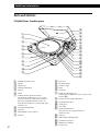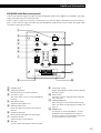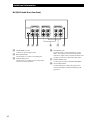
1
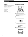
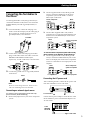
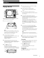
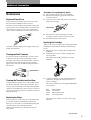
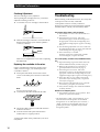
4-229-643-11(1)
Stereo Turntable
System Package
Operating Instructions
PMPK-DJ9000
©2000 Sony Corporation
WARNING
To prevent fire or shock
hazard, do not expose
the unit to rain or
moisture.
For the customers in the
U.S.A.
This symbol is intended to alert the user
to the presence of uninsulated
“dangerous voltage” within the
product’s enclosure that may be of
sufficient magnitude to constitute a risk
of electric shock to persons.
This symbol is intended to alert the user
to the presence of important operating
and maintenance (servicing)
instructions in the literature
accompanying the appliance.
CAUTION
You are cautioned that any changes or
modifications not expressly approved in
this manual could void your authority
to operate this equipment.
2
INFORMATION
This equipment has been tested and
found to comply with the limits for a
Class B digital device, pursuant to Part
15 of the FCC Rules. These limits are
designed to provide reasonable
protection against harmful interference
in a residential installation. This
equipment generates, uses, and can
radiate radio frequency energy and, if
not installed and used in accordance
with the instructions, may cause
harmful interference to radio
communications. However, there is no
guarantee that interference will not
occur in a particular installation. If this
equipment does cause harmful
interference to radio or television
reception, which can be determined by
turning the equipment off and on, the
user is encouraged to try to correct the
interference by one or more of the
following measures:
• Reorient or relocate the receiving
antenna.
• Increase the separation between the
equipment and receiver.
• Connect the equipment into an outlet
on a circuit different from that to
which the receiver is connected.
• Consult the dealer or an experienced
radio/TV technician for help.
Owner’s Record
The model and serial numbers are
located at the rear. Record these
numbers in the spaces provided below.
Refer to them whenever you call upon
your Sony dealer regarding this
product.
Model No.
Serial No.
For the customers in Canada
CAUTION
TO PREVENT ELECTRIC SHOCK, DO
NOT USE THIS POLARIZED AC PLUG
WITH AN EXTENSION CORD,
RECEPTACLE OR OTHER OUTLET
UNLESS THE BLADES CAN BE FULLY
INSERTED TO PREVENT BLADE
EXPOSURE.
Precautions
On safety
• Before operating the unit, check that
the operating voltage of your unit is
identical with that of your local
power supply.
• Should any solid object or liquid fall
into the cabinet, unplug the unit and
have it checked by qualified
personnel before operating it any
further.
• Unplug the unit from the wall outlet
if it is not to be used for an extended
period of time. To disconnect the
cord, pull it out by the plug. Never
pull the cord itself.
• The unit is not disconnected from the
AC power source (mains) as long as it
is connected to the wall outlet, even if
the unit itself has been turned off.
• The nameplate indicating operating
voltage, power consumption, etc. is
located on the rear exterior.
On placement
• Place the unit on a level surface.
• Avoid placing the unit near electrical
appliances (such as a television, hair
dryer, or fluorescent lamp) which
may cause hum or noise.
• Place the unit where it will not be
subject to any vibration, such as from
speakers, slamming of doors, etc.
• Keep the unit away from direct
sunlight, extremes of temperature,
and excessive dust and moisture.
On repacking
Keep the carton and packing materials.
They provide an ideal container to
transport the unit.
If you have any question or problem
concerning your unit that is not covered
in this manual, please consult your
nearest Sony dealer.
Welcome!
Thank you for purchasing the Sony
Stereo Turntable System Package.
Before operating the system, please
read this manual thoroughly and retain
it for future reference.
TABLE
OF CONTENTS
Getting Started
Unpacking 4
Assembling the Turntable 4
Connecting the Turntables to the Mixer 5
Adjusting the Turntable 6
Main features
• As an entry-level DJ turntable, this
system is designed for easy control
even for the novice DJ.
• A slip mat is supplied to enable
scratch playing.
Convention
The following icon is used in this
manual:
Indicates hints and tips for
making the task easier.
z
Operations
Playing a Record 7
Additional Information
Maintenance 9
Troubleshooting 10
Specifications 11
Parts and Controls 12
3
Getting Started
Unpacking
Assembling the Turntable
Verify that the following items are included with your
Stereo Turntable System Package:
• PS-DJ9000 Stereo Turntable System (2)
• MX-DJ9000 Audio Mixer (1)
• Platter (2)
• Slip mat (2)
• Dust cover (with hinges) (2)
• Counterweight (2)
• Cartridge and headshell (2)
• 45 adaptor (2)
• Audio cord (with ground wire) (2)
• AC power cord (2)
• AC power adaptor cord (1)
• Audio cord (without ground wire) (2)
4
2
5
1
3
4
1
Carefully place the platter onto the spindle.
Make sure the two pins on the bottom of the
platter are properly inserted into the two holes in
the motor, as indicated by the arrows in the
illustration above.
2
Place the slip mat on the platter.
3
Slide the counterweight onto the shaft at the rear
of the tonearm and turn 3 or 4 times in the
direction of the arrow.
4
Insert the headshell into the end of the tonearm.
Turn the locking ring in the direction of the arrow
until the headshell is secure.
5
Insert the hinges on the dust cover into the hinge
pockets on the rear of the cabinet.
Getting Started
Connecting the Turntables to
the Mixer
2
Turntable
INPUT(CH-1)
DJ MIX
LINE1
RETURN
l
PHONO1
L
SEND
R
On each turntable, connect the red plug of an
audio cord to the R output jack, the white plug to
the L output jack, and the ground wire to I
(ground) terminal, as shown below.
Mixer
Stereo component
system
Use the supplied audio cords (with ground wire) to
connect the turntables to the mixer’s CH-1 and CH-2
PHONO INPUT jacks and U (ground) terminal, as
follows:
1
Use the supplied audio cord (without ground
wire) to connect the SEND jack on the stereo
component system to the LINE 1 or LINE 2
INPUT jack on the mixer.
R
L
l: Signal flow
3
Use the other supplied audio cord (without
ground wire) to connect the LINE OUTPUT jack
on the mixer to the RETURN jack on the stereo
component system.
Mixer
OUTPUT
REC
LINE
Stereo component
system
l
DJ MIX
RETURN
SEND
R
L
l: Signal flow
2
On the mixer, connect the red plugs and white
plugs on the other end of each audio cord to the
PHONO R and PHONO L INPUT jacks,
respectively, for CH-1 and CH-2, as shown below.
Mixer
INPUT(CH-2)
LINE2
INPUT(CH-1)
PHONO2
LINE1
L
To connect a stereo component system without a DJ
mixer connector or an amplifier, do the following:
1 Use the supplied audio cord (without ground
wire) to connect the LINE OUTPUT jacks on the
mixer to the input jacks on the stereo component
system or to the LINE or AUX input jacks on the
amplifier.
PHONO1
L
Mixer
Stereo component
system or Amplifier
OUTPUT
R
R
REC
LINE
l
L
3
Connect the ground wires to U (ground) terminal
on the mixer.
Mixer
R
l: Signal flow
LINE or AUX input jacks
Connecting the AC power cord
Note
After connecting all units, connect the AC power cord
from each turntable to an AC wall outlet.
Be sure to connect the ground wire. Failure to do so
will cause a humming noise in the turntable.
Connecting an external signal source
To connect a stereo component system with a DJ
mixer connector, do the following:
1 Remove the jumpers from your stereo component
system.
to the AC~IN
to a wall outlet
Connect the AC power adaptor cord to the rear of the
mixer and the AC power cord from the adaptor to an
AC wall outlet.
to the
ADAPTER
DC 15V IN
to a wall outlet
5
Getting Started
Adjusting the Turntable
7
Before attempting to play any records, be sure to
complete the following steps to properly adjust the
tonearm balance, tracking force and anti-skating dial.
Failure to complete these adjustments will result in
inferior sound quality and may cause permanent
damage to the stylus and record.
Make sure the turntable is level.
2
Set ANTI-SKATING to “0.”
TI
Restrain the counterweight with your other hand so
that it does not rotate along with the scale ring.
0
Turn this ring so that the
“0“ lines up with the index
line.
Index line
8
- SKATI
NG
6
7
AN
1
0
2
3
4
5
1
3
A properly balanced tonearm has a tracking force
of zero. Therefore, rotate the tracking force scale
ring until “0” is aligned to the index line.
When you use the supplied cartridge, turn the
counterweight counterclockwise one full rotation,
and then continue turning it until the index line
comes to 1. Since one full rotation of the
counterweight yields a tracking force of 3 grams,
this adjustment results in a tracking force of
4 grams, which is the normal requirement for the
supplied cartridge.
You can set a tracking force of 3 to 7 grams.
Set the cueing lever to the down position.
1
Turn the counterweight
counterclockwise one full
rotation, and then a little
more until the index line
is aligned to 1.
When optionally available cartridge is used
The tracking force scale ring is marked in 0.1-gram
units. One full rotation yields a tracking force of
3 grams.
4
Turn up the protective cover to expose the stylus,
and move the tonearm to the space between the
arm stand and the platter.
Take care not to damage the stylus.
5
Balance the tonearm by turning the counterweight
either clockwise or counterclockwise.
When the tonearm is properly balanced
It will remain level with the platter when released.
It should not tilt in the direction of either the headshell
or the counterweight.
6
6
Return the tonearm to the arm stand.
9
Set ANTI-SKATING to the same value as the
tracking force scale ring.
The numbers on the ANTI-SKATING dial indicate
the number of grams in tracking force.
Operations
Operations
Playing a Record
2
1
3
5
4
5
6,7
8,9
3,8,9
6
8
5
Remove the protective cover from the cartridge
and release the arm stopper.
6
Set the cueing lever in the up position.
Move the tonearm to the desired point on the
record.
7
Set the cueing lever to the down position.
The tonearm will descend slowly to the record and
play will begin.
8
If you want to change the pitch, press the
QUARTZ lock button (the QUARTZ indicator will
turn off). Then adjust the pitch by moving the
PITCH ADJ. knob.
The distance from the center position to the
farthest point on the scale represents a change of
10% in the pitch. You can also use the
PITCH BEND + and – buttons to change the pitch
(see “Using the PITCH BEND + and – buttons” on
page 8).
9
If you wish, you can return to normal speed
(33 1/3 or 45 rpm) while the PITCH ADJ. knob is
off center by pressing the QUARTZ lock button
(the QUARTZ indicator will turn on).
Press the QUARTZ lock button again to go back to
the previous pitch setting (the QUARTZ indicator
will turn off).
Before playing a record, be sure the PHONO/LINE
switch on the mixer is set to PHONO.
1
Place a record on the platter.
Note
Place only one record on the platter at a time. If two or
more records are stacked on the platter, the stylus will
not make proper contact with the grooves and the
quality of reproduction will be impaired.
2
Turn the POWER switch to ON.
The strobo lamp, the QUARTZ lock indicator, and
SPEED indicator light up.
Turn the POWER switch on the mixer and
amplifier to ON also.
Note
The PITCH ADJ. knob does not function while the
QUARTZ lock is on (i.e., while the QUARTZ indicator is
on).
10 To adjust the volume, use the respective channel
fader on the mixer, or the volume control on the
stereo component system or amplifier.
To stop play
3
Set PITCH ADJ. knob to the center position.
When the turntable is turned on, the platter speed
is automatically set to 33 rpm. Verify that the
green indicator lights up.
4
Press Bx START/STOP.
The platter starts rotating.
If you select 33 rpm when the turntable is
connected to a 50 Hz power source, the uppermost
row of the strobe dots should appear to stand still.
1
2
50 Hz
60 Hz
33
45
33
3
Set the cueing lever in the up position and return
the tonearm to the arm stand.
Attach the protective cover onto the cartridge to
prevent damage to the stylus.
Press Bx START/STOP.
The platter stops rotating.
Secure the tonearm with the arm stopper.
Turn POWER to OFF.
To pause play
Press Bx START/STOP or set the cueing lever in the
up position to raise the stylus.
45
(Continued)
7
Operations
To play an another part of the record
1
2
3
Set the cueing lever to the up position to raise the
stylus.
Move the tonearm to the desired position.
Set the cueing lever to the down position.
To play a 45 single
Place the supplied 45 adaptor onto the spindle.
Press SPEED to select 45 rpm.
The green indicator changes to red.
After you have finished using the adaptor, return it to
the adaptor tray.
Using the PITCH BEND + and – buttons
You can use the PITCH BEND + and – buttons to
synchronize the beat of the selection playing on one
turntable with the beat of another selection playing on
the other turntable. You can use these buttons even if
the QUARTZ lock button is turned on or off.
1 Use the PITCH ADJ. knob to synchronize the
speed of the selection playing on one of the
turntables with the speed of the selection on the
other turntable.
2 Press the PITCH BEND + and – buttons to
synchronize the beat of both selections. Pressing
and holding down the + or – button causes the
selection to play 10% faster or slower than the
normal playing speed.
z
If the strobe dots are not stationary when the PITCH
ADJ. knob is set to the center position
Adjust the platter speed by sliding the PITCH ADJ.
knob toward + or – until the strobe dots become
stationary.
z
8
If you have an extra headshell, keep it in the
headshell holder.
Additional Information
Additional Information
Procedure for replacing the stylus
Maintenance
1
2
Stylus and Record Care
3
To prevent premature stylus and record wear, clean
the stylus and record before the start of play.
Clean the stylus by brushing it from back to front with
a good-quality stylus-cleaning brush. Do not clean the
stylus with your fingertip. If you use a liquid stylus
cleaner, take care not to moisten the stylus excessively.
Turn off the turntable, mixer and amplifier.
Release the locking ring and remove the shell
from the tonearm.
Grasp the stylus holder and pull it away from the
body of the cartridge.
Stylus holder
4
5
Insert the new stylus by pushing it into the
cartridge receptacle until it is firmly attached.
Reattach the shell to the tonearm.
Replacing the Cartridge
Clean the record by wiping it thoroughly with a goodquality record cleaner.
Cleaning the Shell Terminals
If you notice a drop in sound quality, excessive noise,
or hum, this may be a result of incomplete contact
caused by dust or dirt on the shell terminals. Remove
the shell from the tonearm and wipe the terminals
lightly with a soft cloth, and then reattach the shell to
the tonearm.
When it is necessary to replace the cartridge, detach the
headshell from the tonearm and follow the directions
below.
1 Remove the screws securing the cartridge to the
headshell.
2 Detach the four wires from the cartridge with a
pair of pinchers.
Then detach the cartridge completely from the
headshell.
Shell terminals
3
Cleaning the Turntables and the Mixer
Clean the cabinet and dust cover of the turntables and
the cabinet and panel of the mixer periodically with a
soft dry cloth. Moisten the cloth with a mild detergent
solution to clean difficult-to-remove stains. Do not use
solvents such as alcohol, benzine or thinner, as this will
damage the finish.
Replacing the Stylus
The life expectancy of the stylus tip is about 500 hours.
To maintain optimum sound quality and prevent
damage to your records, we recommend replacing the
stylus before the end of this time duration.
Obtain a replacement stylus (D5107AL) from your
Sony dealer.
Confirm the polarity of each of the terminal pins
on the new cartridge and connect the wires to
them accordingly.
The polarity of the wires on the supplied headshell
are as follows:
Red:
White:
Green:
Blue:
Right channel
Left channel
Right channel earth
Left channel earth
Make sure not to connect the wires to the wrong
polarities.
(Continued)
9
Additional Information
Overhang Adjustment
The arm overhang is factory adjusted.
After replacing the cartridge, however, you should
adjust the overhang as follows:
1 Loosen the screws of cartridge as shown below.
Troubleshooting
Before referring to the check list below, first verify that:
• The power cord is securely connected.
• The speaker cords are securely connected.
Should any problem persist after taking the specified
remedial actions, consult your nearest Sony dealer.
The tonearm skips, skates or fails to advance.
2
Slide the cartridge backward or forward until the
distance between the stylus and the spindle is
15 mm (3/4 inches).
Spindle
15 mm (3/4 inches)
Make sure to retighten the screws after completing
the adjustment.
Replacing the crossfader in the mixer
If the crossfader knob on the mixer makes a noise
when you are moving it, you should replace the
crossfader as follows:
1 Pull up the fader knob, unscrew the exterior
screws on the fader plate, and remove the fader
knob.
CH-1 0
10
5
5
10
0
CH-2
Note
Do not touch the internal screws.
2
Carefully lift the fader and detach the cable.
CH-1 0
3
4
10
5
5
10
0
CH-2
Attach the cable to the new fader and insert the
fader into the mixer.
Screw down the fader plate and return the
fader knob to its original position.
A replacement fader can be purchased at your local
Sony dealer.
10
b The turntable is not level. Place the turntable on a
level surface.
b The tracking force is incorrect. Follow the
instructions on page 6 and set the tracking force to
the appropriate value for the cartridge being used.
(The supplied cartridge requires 4 grams of tracking
force.)
b The anti-skating adjustment is incorrect. Make sure
the ANTI-SKATING dial is set to the value indicated
on the tracking force ring (see page 6).
b The record is dirty or scratched.
Clean the record with a commercially available
record cleaning kit, or replace the record.
Poor sound quality, excessive noise, intermittent sound,
etc…
b Inspect the locking ring on the tonearm and verify
that the headshell is firmly secured (see page 4).
b Make sure the ground wire is connected to U
(ground) terminal on the mixer (see page 5).
b The tracking force is incorrect. Follow the
instructions on page 6 to set the tracking force to the
appropriate value for the cartridge being used. (The
supplied cartridge requires 4 grams of tracking force.)
b The stylus is dirty or worn. Remove dust on the
stylus with a stylus-cleaning brush, or replace the
worn stylus (see page 9).
b Dust or dirt has collected on the record. Clean the
record with a good-quality record cleaner.
b Verify that the cartridge wires within the headshell
are firmly attached.
Rumble or low-frequency howl*.
b The turntable is placed too close to speakers. Move
speakers away from the turntable.
* This phenomenon, called “acoustic feedback,” occurs
when vibrations from the speakers are transmitted
through the air or via solid objects (such as shelves, a
cabinet, or the floor) to the turntable where they are
picked up by the stylus, amplified and reproduced
through the speakers.
Additional Information
Tempo is incorrect.
MX-DJ9000 Audio Mixer
b The rpm setting is incorrect. Set the rpm to that
indicated on the record (i.e., 33 for 33 1/3-rpm
records and 45 for 45-rpm records).
b The PITCH ADJ. knob is not set to the center position.
b The platter speed is incorrect. Adjust the controls on
the bottom of the turntable while observing the strobe
dots to obtain the correct platter speed (see page 7).
Platter does not rotate.
b Make sure the power cord of the turntable is fully
inserted into an AC wall outlet.
Sound is too low or distorted.
b The turntables are not connected to the PHONO
INPUT connectors on the mixer (see page 5).
b The mixer is not correctly connected to the stereo
component system or the amplifier (see page 5).
b The PHONO/LINE switch on the mixer is not set to
PHONO (see page 7).
Specifications
General
Power requirements
U.S.A. and Mexico: 120 V AC, 60 Hz
European countries: 220 - 230 V AC,
50/60 Hz
Other countries: 110 - 120 V/
220 - 240 V AC, 50/60 Hz
Power consumption
10 W
Inputs
2 PHONO, 2 LINE, 1 MIC
Microphone
1.5 mV
Phono
3 mV
Line
150 mV
Output power
7 V (peak-to-peak)
Outputs
1 LINE OUT, 1 REC OUT via RCA
Frequency range
20 - 20,000 Hz, ±3 dB
Distortion
Less than 0.08 %
S/N ratio
70 dB (1 kHz)
Talkover attenuation
–16 dB
Headphones impeadance 16 Ω
Dimensions
Approx. 200 × 80 × 166 mm (7 7/8 ×
3 1/4 × 6 5/8 in) (w/h/d)
Mass
1.6 kg (3 lb 8 oz)
Supplied Accessory
AC power adaptor cord (1)
Audio cord (without ground wire) (2)
PS-DJ9000 Stereo Turntable System
Motor and Platter
Drive system
Motor
Platter
Speeds
Wow and flutter
Signal to noise ratio
Tone Arm
Type
Effective arm length
Overhang
Usable cartridge weight
General
Power requirements
Power consumption
Dimensions
Mass
Direct drive quartz
3 phase 8 pole Brushless DC motor
Aluminum die-cast
Diameter 332 mm (13.1 inches)
Weight 750 g (1.85 lbs)
33 1/3 and 45 rpm
Less than 0.15 % (WRMS)
More than 55 dB (DIN-B)
Design and specifications are subject to change without
notice.
Static balanced S-shaped tonearm with
detachable headshell
230 mm
15 mm
4 g (min.) to 10 g (max.)
U.S.A. and Mexico: 120 V AC, 60 Hz
European countries: 220 - 230 V AC,
50/60 Hz
Other countries: 110 - 120 V/
220 - 240 V AC, 50/60 Hz
15 W
Approx. 450 × 152 × 352 mm (17 11/16 ×
5 11/16 × 13 3/4 in) (w/h/d)
10 kg (22 lbs)
Supplied Accessories
Platter (2)
Slip mat (2)
Dust cover (with hinges) (2)
Counterweight (2)
Cartridge and headshell (2)
45 adaptor (2)
Audio cord (with ground wire) (2)
AC power cord (2)
11
Additional Information
Parts and Controls
PS-DJ9000 Stereo Turntable System
L
M
A
N
B
O
C
P
D
Q
E
R
S
F
T
G
U
H
V
W
I
X
Y
Z
J
K
wj
1
2
3
4
5
6
7
8
9
q;
qa
12
POWER ON/OFF switch
Spindle
Strobo lamp
START/STOP button
Slip mat
Platter
TARGET LIGHT and release button
The TARGET LIGHT allows you to see the
position of the stylus in the dark. Push and
depress the TARGET LIGHT to turn it off.
Push the release button to raise the light again
and turn it on.
Cartridge and headshell
qs
qd
qf
qg
qh
qj
Dust cover
qk
ql
w;
wa
ws
LOCK lever (for height adjustment)
wd
wf
wg
wh
wj
Tonearm
Finger lift
PITCH BEND + and – buttons
Insulator
Headshell holder
Counter weight
Hinge
45 adaptor
height adj (adjusting) lever
Use this lever to adjust the vertical position of the
tonearm (wd).
ANTI-SKATING dial
Cueing lever
Arm stand
Speed-adjustment hole
This hole is for use by qualified service
technicians only.
PITCH ADJ. (adjusting) knob
QUARTZ lock button
SPEED (33/45) button
Locking ring
Additional Information
MX-DJ9000 Audio Mixer (control panel)
Control of the turntable signal is possible only after the PHONO/LINE switches (5) are set to PHONO. The signal
is then controlled via the CH-1 and CH-2 faders.
Connect a tape recorder, tuner, CD player, cassette deck or any other line signal to the LINE/AUX jacks on the rear
panel. Control of the line signal is possible only after the PHONO/LINE switches are set to LINE. The signal is then
controlled via the respective faders.
A
B
TALK OVER
POWER
ON
OFF
C
MIC LEVEL
D
0
E
F
CUE LEVEL
CUE
CH-1
I
CH-2
10
0
CH-1
PHONO 1
10
CH-2
LINE 1
PHONO 2
LINE 2
+3
LEVEL
LEVEL
0
-3
10
G
10
-8
10
10
5
5
0
0
-13
5
5
0
0
L
CH-1
dB
R
GAIN CH-2
J
0
0
10
10
CROSSFADER
10
5
0
CH-2
CH-1
K
CH-2
CH-1
0
5
10
MIC
PHONES
L
H
1
2
POWER switch
3
CUE select switch
This switch selects CH-1 or CH-2 for headphone
listening.
4
MIC LEVEL control
Adjusts the microphone level.
5
PHONO/LINE switch
Selects the signal to be input to the respective
channel.
TALK OVER button
Press this button to use the microphone.
6
Channel level display
Shows the left and right levels of the output.
7
Channel level knob
Adjusts the level of each channel.
8
MIC jack
You can connect microphones with mono plug.
9
CUE LEVEL control
Adjusts the headphone volume without affecting
the output signal.
q;
GAIN control
Use these controls to adjust the balance between
CH-1 and CH-2.
qa
CROSSFADER knob
Mixes the signal of one channel with that of the
other. For details on replacing the crossfader, see
page 10.
qs
PHONES jack
Use this jack to connect headphones. Accepts
headphone with an impedance of 16 ohms or
more, but 16 ohms is recommended. Select CH-1
or CH-2 with the CUE select switch.
13
Additional Information
MX-DJ9000 Audio Mixer (Rear Panel)
INPUT(CH-2)
OUTPUT
ADAPTER
DC 15V IN
+
LINE
LINE2
INPUT(CH-1)
PHONO2
LINE1
PHONO1
L
L
R
R
–
M
14
REC
N
O
qd
ADAPTER DC 15V IN
Connect AC power adaptor here.
qf
REC OUTPUT jacks
Use these jacks to connect a recording unit.
qg
LINE OUTPUT jacks
Use these jacks to connect a stereo component
system or a power amplifier.
P
Q
R
qh
LINE INPUT jacks
Use these jacks to connect CD players or tape
decks. Line signals from musical instruments
with stereo output (such as rhythm machines and
samplers) can also be connected to these jacks.
qj
PHONO INPUT jacks
Use this jacks to connect turntables PS-DJ9000.
U (Ground) terminal
Use this terminal to connect the ground wire
from the turntable to minimize humming and
pop noises.
qk
Sony Corporation
Printed in Malaysia