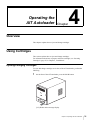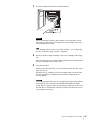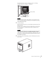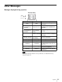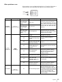
1
4-673-839-12 (1)
AIT Autoloader
Operating Instructions
Before operating the unit, please read this manual
thoroughly and retain it for future reference.
LIB-D81
© 2003 Sony Corporation
WARNING
To prevent fire or shock hazard, do not expose the unit to rain or moisture.
To avoid electrical shock, do not open the cabinet.
Refer servicing to qualified personnel only.
Caution
The mains plug on this equipment must be used to disconnect mains power.
Please ensure that the socket outlet is installed near the equipment and shall be easily accessible.
NOTICE
Use the power cord set approved by the appropriate testing organization for the specific countries where this unit is to be
used.
Achtung
Zur Trennung vom Netz ist der Netzsecker aus der Steckdose zu ziehen, welche sich in der Nähe des Gerätes befinden
muß und leicht zugänglich sein soll.
Hinweis
Der höchste Schalldruckpegel beträgt 70 dB(A) order weniger gemäß ISO7779.
Ratings
Voltage
AC 100 V - 240 V
Current
0.7 A - 0.35 A
Frequency
50 / 60 Hz
Max. Ambient Temperature
40°C
A certified power supply cord has to be used with this equipment.
The relevant national installation and/or equipment regulations shall be considered.
A certified power supply cord not lighter than ordinary polyvinyl chloride flexible cord according to IEC 60227
(designation H05VV-F 3G 0.75 mm2 or H05VVH2-F2 3G 0.75 mm2) shall be used. Alternative a flexible cord be of
synthetic rubber according to IEC 60245 (designation H05RR-F 3G 0.75 mm2) shall be used.
Zum Netzanschluss dieses Gerätes ist eine geprüfte Leitung zu verwenden.
Es sind die zutreffenden nationalen Errichtungs- und/oder Gerätebestimmungen zu beachten.
Es ist eine geprüfte flexible PVC-ummantelte Leitung entsprechend IEC 60227 (H05VV-F 3G 0.75 mm2 oder H05VVH2F 3G 0.75 mm2) zu verwenden. Andernfalls ist eine flexible Leitung aus synthetischem Gummi entsprechend IEC 60245
(Bauartkurzzeichen H05RR-F 3G 0.75 mm2) zu verwenden.
2
INFORMATION
You are cautioned that any changes or modifications not expressly approved in this manual could void your authority to
operate this equipment.
Note: This equipment has been tested and found to comply with the limits for a Class B digital device, pursuant to Part 15
of the FCC Rules. These limits are designed to provide reasonable protection against harmful interference in a residential
installation.
This equipment generates, uses, and can radiate radio frequency energy and, if not installed and used in accordance with
the instructions, may cause harmful interference to radio communications. However, there is no guarantee that interference
will not occur in a particular installation. If this equipment does cause harmful interference to radio or television reception,
which can be determined by turning the equipment off and on, the user is encouraged to try to correct the interference by
one or more of the following measures:
• Reorient or relocate the receiving antenna.
• Increase the separation between the equipment and receiver.
• Connect the equipment into an outlet on a circuit different from that to which the receiver is connected.
• Consult the dealer or an experience radio/TV technician for help.
The shielded interface cable recommended in this manual must be used with this equipment in order to comply with the
limits for a digital device pursuant to Subpart B of Part 15 of FCC Rules.
If you have any questions about this product, please access Sony Support Center written in the warranty card.
Declaration of Conformity
Trade Name:
SONY
Model No.:
LIB-D81
Responsible Party:
Sony Electronics Inc.
Address:
680 Kinderkamack Road Oradell, NJ 07649-1601
Telephone No.:
201-930-6972
This device complies with Part 15 of the FCC Rules. Operation is subject to the following two conditions:
(1) This device may not cause harmful interference, and
(2) This device must accept any interference received, including interference that may cause undesired operation.
Ratings are indicated on the rear, while regulatory agency marks are separately affixed on the bottom.
3
Table of Contents
Chapter 1 Introduction
Overview.......................................................................7
Product Features and Functions ...............................8
Front ................................................................................ 8
Rear ................................................................................. 9
Interior (Front) .............................................................. 10
AIT Drive (Front).......................................................... 11
System Structure.......................................................12
Compatible Cartridges ..............................................12
AIT Cartridges .............................................................. 12
Cleaning Cartridge ........................................................ 13
Software .....................................................................13
Precautions ................................................................13
Chapter 2 Installation
Overview.....................................................................14
Unpacking ..................................................................14
Package Contents .....................................................15
Preparing the Host Computer ..................................15
Installing the AIT Autoloader....................................16
Connecting the Power Cable....................................17
Connecting to the Host Computer ...........................17
Setting the DIP Switches ..........................................19
Setting the SCSI ID ....................................................21
Connecting SCSI Peripheral Devices ......................22
Turning the Power On/Off .........................................22
Setting Cartridges .....................................................24
Preparing Cartridges ..................................................... 24
Inserting Cartridges....................................................... 25
Setting Application Software....................................27
4
Chapter 3 Basic Usage
Overview.....................................................................28
Control Panel .............................................................28
Using the Control Panel ................................................ 28
Message Display ........................................................... 29
Warnings ....................................................................29
Errors..........................................................................30
Disaster Recovery Function .....................................31
Assigned Element Addresses ..................................32
Handling the Cartridges............................................32
Handling........................................................................ 32
Storing........................................................................... 33
Maintenance...............................................................33
Chapter 4 Operating the AIT Autoloader
Overview.....................................................................34
Using Cartridges........................................................34
Ejecting/Changing Cartridges ....................................... 34
Chapter 5 Cleaning the AIT Drive
Overview.....................................................................37
Cleaning the AIT Drive ..............................................37
Appendix
Cleaning the Air Filter ...............................................41
Troubleshooting ........................................................42
Transporting the AIT Autoloader .............................44
Hardware Specifications...........................................45
Hardware ....................................................................... 45
Memory......................................................................... 45
SCSI Cable and Terminator Specifications .............46
SCSI Cable .................................................................... 46
SCSI Cable Length........................................................ 46
SCSI Specifications...................................................46
About the SCSI Components ........................................ 46
About the SCSI Bus ...................................................... 46
Error Code List ..........................................................47
Other Messages.........................................................52
Index ...........................................................................55
5
© 2003 Sony Corporation. All rights reserved.
Trademarks
• Sony, StorStation and Advanced Intelligent Tape are trademarks or registered trademarks of Sony Corporation in this
country, other countries, or both.
• Other product names are trademarks or registered trademarks of their respective owners in this country, other countries,
or both.
6
Introduction
Chapter
1
Overview
The LIB-D81 is a desktop AIT (Advanced Intelligent Tape) automatic loader
(hereafter, “AIT autoloader”) with a built-in AIT drive. Up to 8 cartridges can
be inserted in the AIT autoloader. The unit can also be connected to and used
with a workstation or server.
Up to 8 cartridges can be used
Up to 8 AIT cartridges can be used. Cartridges can be replaced from the front
panel. The following types of cartridges can be used in this AIT autoloader:
• AIT-3 cartridge: records up to 1.6 terabytes of data
• AIT-2 cartridge: records up to 0.8 terabytes of data
• AIT-1 cartridge: records up to 0.56 terabytes of data
Notes
• Cartridges that can be used vary according to the type of built-in drive.
• The memory capacity mentioned above assumes a data compression ratio of
2:1.
Compact
Because of its compact size (170 × 350 × 224 mm) and light weight (approx. 7
kg), the LIB-D81 is the perfect desktop AIT Autoloader.
Wide LVD SCSI compliant
The AIT autoloader is Wide LVD SCSI compliant.
Chapter 1 Introduction
7
Product Features and Functions
Front
1
2
AIT LIBRARY LIB-D81
ERROR
WARNING
CLEAN
DOOR
3
CLEANING
6 5 4
7
A Ventilation Holes
Be careful not to block the ventilation holes. If the ventilation holes are blocked,
the AIT autoloader may overheat, resulting in damage.
B Front Door
Used in inserting and ejecting AIT cartridges. Press the DOOR button to unlock
and open the door. The AIT autoloader cannot operate when the door is open,
therefore when inserting or replacing a cartridge, be that the door is securely
closed. When the door is closed it locks automatically.
C DOOR Button
Press to open the front door. Do not press this button while the AIT autoloader
is operating.
D CLEAN Button
Insert the cleaning cartridge in slot CL/8 and press for at least three seconds to
clean the AIT drive.
E Message Display
The message display displays how many cartridges are in the AIT autoloader.
When in normal standby state, it displays the status of the AIT autoloader.
F ERROR/WARNING LED
Lights or flashes orange when a specific operation is necessary or an error
occurs. When it lights it indicates a warning, whereas when it flashes it indicates
an error. When this happens, a 2-character code appears on the message display.
For details about these codes, see “Error Code List” (page 47), “Other
Messages” (page 52), or the code reference table.
G CLEANING LED
Flashes green when the AIT drive is in need of cleaning. For details about
cleaning the AIT drive, see “Cleaning the AIT Drive” (page 37).
Chapter 1 Introduction
8
Rear
1
2
3
4
7
6
5
A Setup DIP Switches and DIP Switch Cover
Used to set up the AIT autoloader. Remove the screws and cover to access the
DIP switches. For details, see “Setting the DIP Switches” (page 19).
B Ventilation Holes
Please be careful not to block the ventilation holes. If the ventilation holes are
blocked, the AIT autoloader may overheat, resulting in damage.
C Power Switch
To turn the AIT autoloader on or off, press this power switch. When you restart
the AIT autoloader, be sure to wait at least 10 seconds before turning it on again.
D Power Supply Connector
Plug the provided power cord into this connector.
E SCSI connector 1 6 SCSI connector 2
For information about connecting the SCSI connectors, see “Connecting to the
Host Computer” (page 17) and “Connecting SCSI Peripheral Devices” (page
22) in Chapter 2, “Installation”.
F SCSI ID Setup Switch
Used to set the SCSI ID of the AIT autoloader. For details, see“Setting the SCSI
ID” (page 21).
Chapter 1 Introduction
9
Interior (Front)
2
3
1
4
5
AIT LIBRARY LIB-D81
ERROR
WARNING
CLEAN
DOOR
CLEANING
A Front Door
B Air Filter
Periodically clean the air filter with a vacuum cleaner (we recommend monthly
cleaning). For details about how to replace the air filter, see “Cleaning the Air
Filter” (page 41).
C Cartridge Case
You can insert up to eight AIT cartridges in the case. Slots are numbered 1 to 8,
from the highest slot down. When using it, make sure that you insert the
cleaning cartridge in slot CL/8 (the lowest slot).
D AIT Drive
The AIT autoloader is equipped with one AIT drive.
E Elevator
Lowers cartridges to the AIT drive and returns them to their slots. When you
turn on the AIT autoloader, the elevator moves up and down counting the
cartridges, whose number appears on the message display.
Chapter 1 Introduction
10
AIT Drive (Front)
1
BUSY
4
TAPE
3
STATUS
2
A Cartridge Slot
Used to insert and eject AIT cartridges from the AIT drive.
B STATUS LED
Lights when the cartridge in the drive is write-protected. It flashes in the
following situations.
Drive needs cleaning
Repetitive long on, short off.
During cleaning; tape is spent
Regular flashing.
Drive is malfunctioning
Repetitive two short on, one long off.
C TAPE LED
Lights when a cartridge is being loaded. It flashes in the following situations.
When inserting or ejecting a cartridge
Regular flashing.
Cartridge is spent
Repetitive long on, short off.
D BUSY LED
Lights when data is transferred through the SCSI interface. Flashes regularly
when data is read from or written to a cartridge.
Do not restart the AIT autoloader when this LED is lit as this may cause read
and write errors, or irreparable damage to the data cartridge.
Chapter 1 Introduction
11
System Structure
To obtain the best performance out of your AIT drive, we recommend that you
connect the AIT autoloader to a host computer equipped with an Ultra 160 Wide
SCSI LVD/SE interface. The autoloader is controlled through the host
computer.
Computer
Ethernet (example)
LIB-D81
68-pin cable
Host computer
Wide SCSI
AIT LIBRARY LIB-D81
ERROR
WARNING
CLEANING
CLEAN
DOOR
Wide SCSI peripheral devices
Note
A SCSI host adapter card must be installed in the host computer.
Compatible Cartridges
This section describes what AIT cartridges are used in the AIT autoloader.
AIT Cartridges
To achieve the maximum transfer rate and recording capacity, use the
appropriate type of AIT cartridge for your drive. For information on recording
capacities, see “Hardware Specifications” (page 45) in the “Appendix”.
AIT-1 Drive
AIT-1 mark
AIT-2 Drive
AIT-1 mark
AIT-2 mark
Chapter 1 Introduction
12
AIT-3 Drive
AIT-1 mark
AIT-2 mark
AIT-3 mark
Caution
Do not use 8 mm video tapes sold at stores. An 8 mm video tape looks a lot like
an AIT cartridge, but has different specifications. Do not use any other
cartridges other than AIT cartridges.
Cleaning Cartridge
To clean the AIT drive, use an AIT Cleaning cartridge (sold separately). For
information on cleaning, see “Cleaning the AIT Drive” (page 37) in Chapter 5,
“Cleaning the AIT Drive”.
Software
For guidance on application software that can be used with the AIT autoloader
and supported operating systems, contact your dealer.
Precautions
• Use cartridges suited to the type of AIT drive installed. Using cartridges other
than AIT cartridges may cause improper operations. For information about
cartridges that can be used with the AIT autoloader, see “Compatible
Cartridges” (page 12).
• Do not insert anything except AIT cartridges in the slot of the cartridge case,
as doing so may result in damage.
Chapter 1 Introduction
13
Installation
Chapter
2
Overview
This chapter explains general procedures for positioning the AIT autoloader,
connecting it to the host computer and turning on the AIT autoloader. This
chapter also explains initial setup. Installation and setup procedures may vary
depending on your system.
Unpacking
Note
You will need the box and packing materials if you wish to move or transport
the AIT autoloader in the future. Retain them for future use.
1
Remove the AIT autoloader from the box as indicated on the box.
Remove the packing materials, such as plastic covers and tapes.
Chapter 2 Installation
14
Package Contents
After opening the box, make sure that all the following items are present.
Contact your dealer if anything is missing.
•
•
•
•
•
•
LIB-D81 (1)
Power cable (1)
SCSI terminator (1)
Cleaning cartridge (1)
Quick Start Guide (1)
CD-ROM (containing this document) (1)
Note
In addition to the above, other documentation and/or documents may be
included in the package.
Preparing the Host Computer
Prepare the host computer before installing the AIT autoloader as follows.
1
Make sure that a SCSI host adapter card is installed in the host computer.
2
Install the application software supporting the autoloader on the host
computer.
For guidance on application software that can be used with the AIT
autoloader and supported operating systems, contact your dealer.
Chapter 2 Installation
15
Installing the AIT Autoloader
The autoloader weighs about 7 kg (15.4 lb.) and has the following dimensions.
Before installing the autoloader, make sure that the surface is appropriate.
N
Note
Install the AIT autoloader on a horizontal surface near an AC power outlet. Also
leave a gap of about 150 mm (5.9 in.) behind the rear of the unit to allow air to
circulate.
220 mm (8.7 in.)
224 mm (8.8 in.)
(including rubber
feet)
350 mm (13.8 in.)
170 mm
(6.7 in.)
Caution
Make sure that you position the AIT autoloader as indicated in the illustration.
Correct operation is not guaranteed if you place the AIT autoloader on its side.
50 mm (2.0 in.)
Rear
Front
170 mm (6.7 in.)
150 mm
(5.9 in.)
350 mm (13.8 in.)
50 mm (2.0 in.)
Chapter 2 Installation
16
Connecting the Power Cable
1
Make sure that the power switch on the rear of the AIT autoloader is in the
off position (a is depressed).
2
Connect one end of the power cable to the power supply connector and the
other end to the power outlet.
Connecting to the Host Computer
Connect the AIT autoloader and the host computer with a SCSI cable. This
section explains general connection steps. To connect, use an Ultra2 Wide SCSI
LVD cable commonly sold in stores. However, when using a model equipped
with an AIT-3 drive, use an Ultra 160/m SCSI LVD cable. The autoloader side
uses the 68-pin half pitch connector.
When connecting other SCSI devices along with the AIT autoloader, see
“Connecting SCSI Peripheral Devices” (page 22).
Caution
• Do not connect the AIT autoloader to the HVD (High Voltage Differential)
SCSI bus. If connected, the autoloader or other devices on the SCSI bus may
be damaged.
Chapter 2 Installation
17
• When connecting the Wide SCSI cable, turn off all of the connecting devices,
including the AIT autoloader and the host computer.
• When connecting the AIT autoloader as the last device on the SCSI bus, be
sure to attach the provided terminator.
• In LVD (Low Voltage Differential) SCSI, make the total length of the SCSI
cable (internal and external), which connects the host computer and the device
at the end of the SCSI bus, shorter than 12 m (39.4 ft.). (The length of the AIT
autoloader internal cable is 0.5 m (19.7 in.).)
• Using SCSI cables longer than 30 cm (11.8 in.) to connect between devices is
recommended.
• SCSI cables cannot be branched.
Notes
• For information about the SCSI bus, see “SCSI Specifications” (page 46) in
the “Appendix”.
• Prepare the necessary SCSI cables. For information about SCSI cable
specifications, see “SCSI Cable and Terminator Specifications” (page 46) in
the “Appendix”.
1
Confirm that the power to the host computer and AIT autoloader are off.
2
Connect the SCSI cable and terminator as shown in the figure below.
1 Use a commercial SCSI cable to connect the AIT autoloader to the host
computer.
2 Connect the provided terminator to connector.
Terminator
2
1
Host computer
Chapter 2 Installation
18
Setting the DIP Switches
By setting the DIP switches at the back of the AIT autoloader, you can:
• Supply power to the SCSI terminator (on by default)
When you are using several SCSI devices, you can set the AIT autoloader to
supply power to the SCSI terminator.
• Display warning messages when specific parts reach the end of their life or
when in need of cleaning (on by default)
You can set the AIT autoloader to display warning messages when specific
parts reach the end of their service life or when need of cleaning (weekly).
• Use the autoloader option function (off by default)
You can set the AIT autoloader to monitor the AIT drive status on a regular
basis, as well as automatically eject and insert cartridges.
Rear
DIP switches for setup
0 1
off on
1
2
3
4
5
6
7
8
The default settings of the DIP switches are as follows.
DIP SW (DEFAULT)
0 1
off on
1
TERM PWR
2
MAINTENANCE
3
LOADER SEL
4
5
CONTINUOUS
AUTOLOAD
6
RMIC
7
RESERVED
8
RESERVED
Switches are off when in the “0” position and on in the “1” position. The default
setting of the DIP switches is indicated in brackets.
1 TERM PWA (on)
0: Power is not supplied to the SCSI terminator.
1: Power is supplied to the SCSI terminator.
Chapter 2 Installation
19
2 MAINTENANCE (on)
0: Warning messages are not displayed when specific parts reach the end of
their service life or when in need of cleaning (weekly).
1: Warning messages are displayed when specific parts reach the end of their
service life or when in need of cleaning (weekly).
3 LOADER SEL (off)
0: The autoloader option function is not active.
1: The autoloader option function is active.
When this setting is active, the AIT autoloader monitors the AIT drive
status on a regular basis, as well as perform the following.
- When a cartridge is unloaded, it is automatically ejected and returned to
its original slot, and the cartridge from the next slot is inserted into the
AIT drive.
- When the cleaning cartridge is in the AIT drive and cleaning ends, the
cleaning cartridge is automatically ejected and returned to its original
slot, and the cartridge from the next slot is inserted into the AIT drive.
4 CONTINUOUS (off)
0: The autoloader option function is not in continuous mode.
1: The autoloader option function is in continuous mode.
You can use this setting only if LOADER SEL in set to “1”. When you
activate this setting and the autoloader option function returns a cartridge
to slot CL/8 (the last slot), it automatically inserts the cartridge from the
newest slot into the AIT drive.
5 AUTOLOAD (off)
0: The autoloader option function is not in automatic loading mode.
1: The autoloader option function is in automatic loading mode.
You can use this setting only if LOADER SEL in set to “1”. When you
activate this setting and turn on the AIT autoloader, the AIT autoloader
automatically inserts the cartridge from the newest slot in the AIT drive.
6 RMIC (off)
This function is not supported.
7 RESERVED (off)
Extension. Do not use.
8 RESERVED (off)
Extension. Do not use.
1
Make sure that the power switch on the rear of the AIT autoloader is in the
off position (a is depressed).
2
Use a pointed object such as a machinist’s screwdriver to change the
settings of the DIP switches.
3
Press the power switch to turn on the power.
If you change the SCSI ID settings or connect SCSI peripheral devices, do
not turn on the power from here. Instead, see “Setting the SCSI ID” (page
21) and “Connecting SCSI Peripheral Devices” (page 22).
Chapter 2 Installation
20
Setting the SCSI ID
Use the SCSI ID switches at the back of the AIT autoloader to set the AIT drive
and/or AIT autoloader SCSI ID.
The default settings of the switches are as follows.
Use the upper switch to set the AIT drive SCSI ID and the lower switch to set
the AIT autoloader SCSI ID.
3456
B CD
3456
A
E
789
F012
A
E
789
F012
AIT drive SCSI ID
B CD
AIT autoloader SCSI ID
Caution
• Do not set the same SCSI ID for the AIT drive and AIT autoloader.
• Make sure that you perform these settings before turning on the AIT
autoloader.
1
Make sure that the power switch on the rear of the AIT autoloader is in the
off position (a is depressed).
2
Use a pointed object such as a machinist’s screwdriver to turn the switches
until their arrows match the setting that you want.
3
Press the power switch to turn on the power.
If you want to connect SCSI peripheral devices, see “Connecting SCSI
Peripheral Devices” (page 22).
Chapter 2 Installation
21
Connecting SCSI Peripheral Devices
SCSI peripheral devices can be connected to the SCSI connectors of the AIT
autoloader. The SCSI configuration of the autoloader is as shown below.
Connect the devices according to the system environment.
AIT drive
SCSI ID : 0
SCSI connectors
Loader controller
SCSI ID : 1
Notes
• The default factory settings of the SCSI IDs are as follows.
- AIT drive: 0
- Loader:
1
• Do not use repetitive SCSI IDs.
• Connect peripheral devices before turning on the AIT autoloader and host
computer.
Turning the Power On/Off
Turn On the Power
Turn on the AIT autoloader, then turn on the host computer.
1
Press the power switch on the rear of the autoloader, as illustrated.
Chapter 2 Installation
22
The message display changes as follows and the startup process begins.
(Startup takes several minutes.)
During startup, the following appears on the message display.
Moves gradually up and down during the elevator check.
Indicates the startup phase, from 0 to 3.
When startup is complete, the message display indicates the number of
cartridges in the AIT autoloader.
Starting up
2
Startup complete
After pressing the standby switch on the autoloader’s front panel, wait at
least 10 seconds before turning on the host computer.
Notes
• If you start the host computer before the autoloader, the SCSI ID is not
detected correctly. Therefore, you must always start the autoloader
before starting the host computer.
• If the autoloader does not work as above, see “Troubleshooting” (page
42).
Chapter 2 Installation
23
Turn Off the Power
Press the power switch on the rear of the AIT autoloader to turn it off.
Caution
Do not turn off the AIT autoloader when it is in use or there is a cartridge in the
AIT drive, as this could damage data.
Note
After turning the AIT autoloader off, wait at least 10 seconds before turning it
on again.
Setting Cartridges
Prepare cartridges and insert them into the AIT autoloader.
Preparing Cartridges
Make sure that cartridges are not write-protected and prepare them for use.
Verify whether the write-protected tab is in the write-enable position. If the tab
is orange, data can be written to a cartridge.
AIT-1
AIT-2, AIT-3
Lid
If the tab is moved to the left, data
can be written to and erased from
the cartridge.K
If the tab is moved to the right, data
cannot be written or accidentally
erased from the cartridge.k
Lid
If the tab is lowered, data can be
written to and erased from the
cartridge.j
If the tab is raised, data cannot be
written to or accidentally erased
from the cartridge.J
Chapter 2 Installation
24
Inserting Cartridges
Insert cartridges into the AIT autoloader as outlined below.
1
On the front of the AIT autoloader, press the DOOR button.
[o P] flashes on the message display.
The AIT autoloader is preparing to open the front door. Wait until the
display stops flashing, which may take up to a minute.
Flashing display
Steady display
When the display stops flashing, the front door unlocks.
Note
To prevent the front door from opening during operation, it automatically
locks when it is closed. Attempting to open the door without unlocking it
may damage the AIT autoloader.
Chapter 2 Installation
25
2
When you are certain that [o P] on the message display has stopped
flashing, open the front door as illustrated here.
When you open the front door, [o P] remains displayed on the message
display.
Caution
• It is possible for the host computer to prevent the front door from being
opened or closed. When this is the case and you press the DOOR button,
the ERROR/WARNING LED lights and [0 5] appears on the message
display indicating that the door cannot be opened.
• If the front door is not opened within 3 minutes of [o P] appearing
steadily on the message display, the door is automatically locked and the
message display reverts to normal.
3
Insert cartridges into the AIT autoloader.
Make sure that you insert cartridges in the right direction, and push them in
the AIT autoloader until you hear a click.
Slot in the AIT autoloader are numbered 1 to 8, from the highest slot down.
(Slot numbers match SCSI element numbers.)
AIT LIBRARY LIB-D81
ERROR
WARNING
CLEAN
DOOR
CLEANING
Caution
The AIT autoloader contains a large number of wires and parts. Do not
touch any part other than the slots inside the AIT autoloader as this may
lead to damage and/or injury.
Chapter 2 Installation
26
4
Close the front door.
When you hear the door click, it is closed. Make sure that the door clicks
when you close it.
When the door is completely closed, the cartridges that you inserted into
the AIT autoloader are counted and their number is displayed on the
message display.
Caution
If cartridges protrude from slots or are otherwise improperly inserted into
slots inside the AIT autoloader, the ERROR/WARNING LED lights
orange and [0 1] appears on the message display, indicating an error, and
the front door is automatically unlocked. Open the front door and correct
any problems as necessary.
Setting Application Software
Make the necessary settings to be able to use the AIT autoloader. Refer to the
documentation of the application software used with the AIT autoloader for
details about the necessary settings.
Chapter 2 Installation
27
Basic Usage
Chapter
3
Overview
This chapter explains the control panel, basic settings, handling cartridges,
element address assignments, and Maintenance.
Control Panel
You can use the control panel to display information about the AIT autoloader
and clean the AIT drive.
This section explains the operation of the control panel and the information
displayed by the message display.
Using the Control Panel
Use the control panel to perform the following.
• Display information related to the AIT autoloader.
• Clean the AIT drive.
• Perform disaster recovery.
Note
Disaster recovery is a function through which all the data on the host computer
is backed up on cartridges, which can then be used to restore your system in the
unlikely event of a catastrophic failure, for example.
Chapter 3 Basic Usage
28
Message Display
The message display displays the current number of cartridges in the AIT
autoloader, the AIT autoloader’s operational status, as well as warning and error
messages.
Left of the display
ERROR
WARNING
CLEANING
Right of the display
Normal display
• The left of the display indicates the operational status of the autoloader.
• The right of the display indicates the current number of cartridges in the AIT
autoloader.
Display during user operations, requests to users, error messages
A two-character code appears on the display. For details about the meaning of
the various codes, see “Error Code List” (page 47) and “Other Messages” (page
52).
Warnings
When the AIT drive needs to be cleaned or specific parts need to be replaced at
the end of their service life, LED light on the front panel of the AIT autoloader
and messages appear on the message display, as illustrated here.
Cleaning request
The CLEANING LED flashes green and the [C L] code flashes on the message
display. By default, you are notified that the AIT drive needs cleaning when the
AIT autoloader has been online for approximately a week.
ERROR
WARNING
CLEANING
Chapter 3 Basic Usage
29
High internal temperature
The ERROR/WARNING LED lights orange and the [0 6] code appears on the
message display. Suspend operation or lower ambient temperature. When the
AIT autoloader internal temperature returns to normal levels, the ERROR/
WARNING LED goes out. It is possible for the air filter to become clogged with
dust or other particles. To prevent this from happening, be sure to clean the air
filter regularly. For details, see “Maintenance” (page 33).
ERROR
WARNING
CLEANING
Specific parts have reached the end of their service life
The ERROR/WARNING LED lights orange and the [0 7] code appears on the
message display. Contact customer service.
ERROR
WARNING
CLEANING
Errors
When an error occurs in the AIT autoloader, the ERROR/WARNING LED
flashes orange and an error code appears on the message display. For
information about error codes, see “Error Code List” (page 47) in the
“Appendix”.
Example: Problem with a cartridge
[C ] and [XX], where “XX” is the error code, appear alternatively on the
message display.
Example: Problem with the autoloader
[L ] and [XX], where “XX” is the error code, appear alternately on the message
display.
Chapter 3 Basic Usage
30
Example: Problem with the drive
[d ] and [XX], where “XX” is the error code, appear alternately on the message
display.
Note
For illustration purposes, we have used the autoloader in error code examples
throughout the document.
Disaster Recovery Function
Disaster recovery is a function through which all the data on the host computer
is backed up on cartridges, which can then be used to restore your system in the
unlikely event of a catastrophic failure, for example. Perform disaster recovery
with the application software on the host computer.
For details about operations and settings on the host computer, refer to the
documentation accompanying the computer and software applications.
1
Prepare to perform disaster recovery.
1 Create a disaster recovery tape with the host computer.
2 Place the AIT drive in Disaster recovery mode.
Send the AIT drive mode selection command from the host computer.
The AIT drive enters Disaster recovery mode.
You can also place the AIT drive in Disaster recovery mode by following
the instructions of step 2 below.
2
Begin disaster recovery.
1 Insert the disaster recovery tape into slot 1.
2 Simultaneously press the CLEAN and DOOR buttons at the front of the
AIT autoloader for at least 5 seconds. The AIT drive enters Disaster
recovery mode. When the AIT drive enters Disaster recovery mode, [d r]
appears flashing on the message display.
3 Turn off the AIT autoloader, wait approximately 10 seconds, then restart
it.
The disaster recovery tape is automatically inserted into the AIT drive.
Refer to the documentation accompanying the computer and software
applications to perform the disaster recovery procedure.
Chapter 3 Basic Usage
31
Assigned Element Addresses
An element is a physical location where a cartridge is kept. Applications use
element addresses to differentiate between the elements of the AIT autoloader.
In AIT autoloader, the element addresses are assigned to the cartridge slots and
the AIT drive as illustrated below.
Note
Because element addresses of the AIT autoloader are fixed numbers, they
cannot be reassigned.
1
2
3
4
5
6
7
8
AIT drive (element address 82)
Elevator (element address 0)
Handling the Cartridges
When handling or storing the cartridges, note the following.
Handling
• Do not subject the cartridges to strong vibrations. Do not drop the cartridges.
• When loading a cartridge into the AIT autoloader, the lid of the cartridge
opens up automatically. Do not manually open the lid and touch the interior
tape.
• The cartridge is preadjusted at the factory, so do not disassemble it.
• The tab of a cartridge is used to prevent writing to the cartridge by accident.
If the cartridge does not need to be written to, move the tab to write-protect it.
t “Preparing Cartridges” (page 24) in Chapter 2, “Installation”.
Chapter 3 Basic Usage
32
• If the AIT autoloader is used in a high-humidity environment or a location that
is subject to wide variations in temperature, condensation may prevent the
cartridge read/write operation.
• If the cartridge does not need to be written to or read from, do not insert or
eject it too often.
Storing
• Store cartridges in an appropriate environment.
Store cartridges according to the temperature and other surrounding
conditions written on the package. Also, try to keep the temperature and
humidity of the environment constant. Store cartridges out of the direct sun
rays. Do not store them near heating systems. Never place cartridges on a
dashboard or in the glove compartment of a car.
• Store cartridges in a dustless environment.
Eliminate sources of dust. Avoid eating, drinking, or smoking near the storage
location. Also, do not store cartridges near copying machines or printers that
emit toner and paper dust.
• When storing cartridge, set the erase-protection tab so that the data cannot be
over written.
• After removing a cartridge from the autoloader, store it in an appropriate
location as soon as possible.
Avoid, as much as possible, changes of temperature and density,
contamination by dust and scratches made by touching the interior tape.
Maintenance
Perform the following periodically.
• Clean the air filter.
If the front panel air filter becomes clogged with dust, the AIT autoloader may
overheat, resulting in damage. Periodically clean the air filter with a vacuum
cleaner. (We recommend monthly cleaning.) For details about how to remove
the air filter, see “Cleaning the Air Filter” (page 41) in the “Appendix”.
• Clean the AIT drive.
Clean the AIT drive on a weekly basis. You are notified that the AIT drive
needs cleaning by a flashing green CLEANING LED and a message when the
AIT autoloader has been online for approximately a week. If the 2
MAINTENANCE DIP switch at the back of the AIT autoloader is in the off
position, you are not notified when cleaning becomes necessary. By default,
this DIP switch is in the on position. For details, see “Setting the DIP
Switches” (page 19).
Chapter 3 Basic Usage
33
Operating the
AIT Autoloader
Chapter
4
Overview
This chapter explains how to eject and change cartridges.
Using Cartridges
This section explains how to eject and change cartridges.
For information about how to prepare and insert cartridges, see “Inserting
Cartridges” (page 25) in Chapter 2, “Installation”.
Ejecting/Changing Cartridges
To eject and change cartridges set in slots of the AIT autoloader, perform the
following.
1
On the front of the AIT autoloader, press the DOOR button.
[o P] flashes on the message display.
Chapter 4 Operating the AIT Autoloader
34
The AIT autoloader is preparing to open the front door. Wait until the
display stops flashing, which may take up to a minute.
Flashing display
Steady display
When the display stops flashing, the front door unlocks.
Note
To prevent the front door from opening during operation, it automatically
locks when it is closed. Attempting to open the door without unlocking it
may damage the AIT autoloader.
2
When you are certain that [o P] on the message display has stopped
flashing, open the front door as illustrated here.
When you open the front door, [o P] remains displayed on the message
display.
Caution
• It is possible for the host computer to prevent the front door from being
opened or closed. When this is the case and you press the DOOR button,
the ERROR/WARNING LED lights and [0 5] appears on the message
display indicating that the door cannot be opened.
• If the front door is not opened within 3 minutes of [o P] appearing
steadily on the message display, the door is automatically locked and the
message display reverts to normal.
Chapter 4 Operating the AIT Autoloader
35
3
Eject the cartridge from the slot as illustrated below.
AIT LIBRARY LIB-D81
ERROR
WARNING
CLEAN
DOOR
CLEANING
Caution
The AIT autoloader contains a large number of wires and parts. Do not
touch any part other than the slots inside the AIT autoloader as this may
lead to damage and/or injury.
Note
If the cartridge that you want to eject in the AIT drive, see “Transporting
the AIT Autoloader” (page 44) in the “Appendix”.
4
When you want to change cartridges, insert a new cartridge in the empty
slot.
Make sure that you insert cartridges in the right direction, and push them in
the AIT autoloader until you hear a click.
5
Close the front door.
When you hear the door click, it is closed. Make sure that the door clicks
when you close it.
When the door is completely closed, the cartridges that you inserted into
the AIT autoloader are counted and their number is displayed on the
message display.
Caution
If cartridges protrude from slots or are otherwise improperly inserted into
slots inside the AIT autoloader, the ERROR/WARNING LED lights
orange and [0 1] appears on the message display, indicating an error, and
the front door is automatically unlocked. Open the front door and correct
any problems as necessary.
Chapter 4 Operating the AIT Autoloader
36
Cleaning the AIT Drive
Chapter
5
Overview
This chapter explains how to clean the AIT drive.
Cleaning the AIT Drive
When the AIT drive is in need of cleaning, the CLEANING LED flashes green
and the following appears on the message display.
ERROR
WARNING
CLEANING
To clean the AIT drive, insert a cleaning cartridge (sold separately) into the
drive. Make sure that you insert the cleaning cartridge into the slot CL/8 before
you proceed.
Caution
• If there is a cartridge in the AIT drive when you begin cleaning the drive, it is
returned to its original slot before the cleaning procedure starts.
• If the 2 MAINTENANCE DIP switch at the back of the AIT autoloader is in
the off position, you are not notified when cleaning becomes necessary. By
default, this DIP switch is in the on position. In this position, you are notified
to clean the AIT drive when the AIT autoloader has been online for
approximately a week. For details, see “Setting the DIP Switches” (page 19).
1
Prepare your cleaning cartridge.
2
On the front of the AIT autoloader, press the DOOR button, open the front
door, and insert the cartridge into slot CL/8 (the lowest slot).
Chapter 5 Cleaning the AIT Drive
37
For details about how to insert a cartridge into a slot, see “Setting
Cartridges” (page 24) in Chapter 2, “Installation”.
Cleaning cartridge
AIT LIBRARY LIB-D81
ERROR
WARNING
CLEAN
DOOR
CLEANING
Caution
The AIT autoloader contains a large number of wires and parts. Do not
touch any part other than the slots inside the AIT autoloader as this may
lead to damage and/or injury.
3
Close the front door.
When you hear the door click, it is closed. Make sure that the door clicks
when you close it.
When the door is completely closed, the cartridges that you inserted into
the AIT autoloader are counted and their number is displayed on the
message display.
Caution
If cartridges protrude from slots or are otherwise improperly inserted into
slots inside the AIT autoloader, the ERROR/WARNING LED lights
orange and [0 1] appears on the message display, indicating an error, and
the front door is automatically unlocked. Open the front door and correct
any problems as necessary.
4
On the front of the AIT autoloader, press the CLEAN button for at least
three seconds.
Chapter 5 Cleaning the AIT Drive
38
[C L] flashes on the message display and cleaning starts.
Flashing display
When cleaning ends, the cleaning cartridge is returned to slot CL/8 and the
CLEANING LED goes out.
5
When the CLEANING LED goes out, press the DOOR button, open the
front door, and eject the cleaning cartridge.
Caution
• If the CLEANING LED does not go out, it is possible that the cleaning
cartridge is spent. Replace the cleaning cartridge with a new one and
perform the cleaning procedure again.
• If there is a cartridge in the AIT drive when you begin cleaning the drive,
it is returned to its original slot before the cleaning procedure starts.
• If you are writing to a damaged cartridge, unloading may take some time.
For this reason, cleaning can take up to 20 minutes.
Note
If the AIT autoloader cannot clean the AIT drive, the following error
messages may appear.
If there is no cartridge in slot CL/8
The ERROR/WARNING LED lights and [0 3] appears on the message
display.
ERROR
WARNING
CLEANING
If there is an AIT cartridge in slot CL/8
The ERROR/WARNING LED lights and [0 4] appears on the message
display.
ERROR
WARNING
CLEANING
Chapter 5 Cleaning the AIT Drive
39
If cleaning fails for any other reason
The ERROR/WARNING LED flashes, [L ] and [XX] or [d ] and [XX]
(where “XX” is an error code) appear alternately on the message display.
ERROR
WARNING
CLEANING
Or
ERROR
WARNING
CLEANING
Chapter 5 Cleaning the AIT Drive
40
Appendix
Cleaning the Air Filter
Note
Clean the air filter once a month using a vacuum cleaner.
1
Press the DOOR button and open the front door.
2
Turn off the AIT autoloader.
3
Extract the air filter from the AIT autoloader.
Caution
Take care not to cut yourself on the metal corners of the air filter.
4
Clean the air filter with a vacuum cleaner.
5
Reinsert the air filter.
6
Close the front door.
7
Turn on the AIT autoloader.
Appendix
41
Troubleshooting
Before contacting a Sony Service center, please check the following. If the
problem persists, contact a Sony Service center.
The AIT autoloader does not work
•
•
•
•
•
Verify that the power is on.
Verify that the power cable is connected correctly.
Verify that the front door is closed.
Verify that the terminator is attached correctly.
Verify that the SCSI cable is correctly connected from the AIT autoloader to
the host computer.
• Verify that the host computer is on.
• Verify that no error code is displayed on the message display. For information
about error codes, see “Error Code List” (page 47).
• Only restart the AIT autoloader 10 seconds after it is turned off.
The AIT autoloader and the host computer cannot
communicate with each other
• Verify that the SCSI IDs of the autoloader, AIT drive, and host computer are
unique. Duplicate SCSI IDs cannot be used on one SCSI bus. t “Setting the
SCSI ID” (page 21) in Chapter 2, “Installation”.
• Verify that the SCSI cable is connected correctly. t“Connecting to the Host
Computer” (page 17) in Chapter 2, “Installation”.
• Verify that the SCSI adapter card is correctly installed in the computer.
• Verify that all the connected SCSI devices are LVD devices. The AIT
autoloader is an LVD device. Do not connect HDV devices to the autoloader.
• Verify that all the devices on the SCSI bus are Wide SCSI devices. The AIT
autoloader is a Wide SCSI device. All the devices on the SCSI bus must be
Wide SCSI devices. (Wide-Narrow adapters can also be used.)
• Verify that the length of the SCSI cable that connects the host computer and
the AIT autoloader at the end of the SCSI bus is shorter than 12 m (39.4 ft.).
• Verify that the SCSI bus is terminated correctly. t “SCSI Specifications”
(page 46).
• Verify that the AIT autoloader supports the application software. For
guidance on application software that can be used on the AIT autoloader and
on compatible operating systems, contact your dealer.
• Verify that the application software is correctly installed and correctly set up
on the host computer.
• Verify that the host computer was turned on more than 10 seconds after
turning on the autoloader. If the host computer is turned on too soon after
turning on the autoloader, the host computer may not detect the SCSI devices.
Data cannot be written or read even though the
application and the autoloader are working properly
• Verify that the write-protect tab of the cartridge is in the write-enable position.
t “Preparing Cartridges” (page 24) in Chapter 2, “Installation”.
• Only use Sony AIT cartridges. Verify that the AIT drive supports the
cartridges.
• If a cartridge has been used for a long time or very frequently, replace it with
a new cartridge.
• Verify that the cartridge is not damaged.
Appendix
42
• Try cleaning the AIT drive. t “Cleaning the AIT Drive” (page 37) in
Chapter 5, “Cleaning the AIT Drive”.
The cartridges cannot be ejected
• Follow the instructions in “Ejecting/Changing Cartridges” (page 34) in
Chapter 4, “Operating the AIT Autoloader”.
If you are still unable to eject cartridges, please contact your dealer for
assistance.
• If you are unable to eject the cartridge in the AIT drive, perform the following
procedure.
1 On the front of the AIT autoloader, press the DOOR button for
at least five seconds.
[E J] flashes on the message display. The cartridge in the AIT drive is
automatically ejected and returned to its original slot.
The front door is then unlocked and [o P] appears on the message display.
Notes
• When the original position of the cartridge is unknown, such as after
restarting the AIT autoloader, the cartridge is inserted in the highest
available slot.
• When you press the DOOR button for at least five seconds when there is
not cartridge in the AIT drive, [E J] flashes on the message display and
the front door is unlocked.
2 When you are certain that [o P] on the message display has
stopped flashing, open the front door and eject the cartridge.
The front door does not open
If pressing the DOOR button fails to unlock the front door, perform the
following.
• On the front of the AIT autoloader, press the DOOR for at least five seconds.
[E J] flashes on the message display and the front door is unlocked.
• If the above fails, remove the protective cap at the base of the AIT autoloader
as illustrated below, and then use a pointed object such as a ballpoint pen to
press the release button. The front door unlocks allowing you to open it.
Remove the protective cap with a
screwdriver, and then use a pointed
object such as a ballpoint pen to
press the release button.
AIT autoloader base
Appendix
43
Miscellaneous
Verify that the front door is securely closed. The AIT autoloader cannot operate
normally if the front door is not closed.
Transporting the AIT Autoloader
If you are transporting the AIT autoloader for any reason, such as when moving
or repairing the autoloader, make the following preparations.
• When packing, perform the unpacking procedure outlined in “Unpacking”
(page 14) in reverse.
• Eject all the cartridges in the autoloader. If the cartridges cannot be ejected by
normally, see “The cartridges cannot be ejected” (page 43) in
“Troubleshooting”.
• Remove all the cables such as the power cable, the SCSI cable, the terminator,
and the network cable.
Appendix
44
Hardware Specifications
Hardware
AIT Drive
LIB-D81/A1: SDX-400C/L (1)
LIB-D81/A2: SDX-500C/L (1)
LIB-D81/A3: SDX-700C/L (1)
Number of drives that can be installed
One drive
Number of cartridges that can be inserted
Maximum of 8
Data transfer rate
Native
AIT-3
12 MB/s
AIT-2
6 MB/s
AIT-1
4 MB/s
Message display 7-segment LED display, displays 2 characters
LED
Two
External connectors
SCSI
68-pin (2)
Loader
Wide SCSI LVD/SE
Drive
AIT-1 and AIT-2 drives: Ultra Wide SCSI LVD/SE
AIT-3 drive: Ultra 160 SCSI LVD/SE
Operating environment
Temperature: 5ºC to 40ºC
Humidity: 20% to 80%
(Avoid condensation)
Power
AC100 V to 240 V ±10% (50/60 Hz)
Power consumption
AIT-1 Model 40 W (Max)
AIT-2 Model 40 W (Max)
AIT-3 Model 45 W (Max)
External Dimensions
170 (W) × 224 (H) × 350 (D) mm
(6.7 (W) × 8.8 (H) × 13.8 (D) in.)
Mass
7 kg (15.4 lb.)
Memory
AIT-3 cartridge: 1.6 terabytes
AIT-2 cartridge: 0.8 terabytes
AIT-1 cartridge: 0.56 terabytes
(When data compression is 2:1)
Please note: Due to constant improvements, the specifications and outward
appearance of the AIT autoloader may change without prior announcements.
Appendix
45
SCSI Cable and Terminator Specifications
SCSI Cable
For impedance and primary conductor, use a Ultra Wide LVD SCSI cable that
conforms to SCSI-3 specifications. However, when using a model equipped
with an AIT-3 drive, use an Ultra 160/m SCSI LVD cable.
SCSI Cable Length
The total allowable length of SCSI cables used in one LVD SCSI bus is as
follows. (This length includes the length of all internal and external cables.)
• The length of the AIT autoloader internal cable is 0.5 m (19.7 in.).
• If there are more than three devices on an LVD SCSI bus, the total allowable
length is 12 m (39.4 ft.).
SCSI Specifications
This section describes common specifications of SCSI components and SCSI
buses.
About the SCSI Components
The SCSI system is composed of the following components.
• Initiator
This is a host computer system that functions as an initiator program of
commands. The system consists of the application software, the operating
system, the device driver and the SCSI adapter card.
• Bus
By connecting the SCSI cables to the SCSI adapter card, the autoloader and
other devices, a path (or a bus) is created for transferring commands.
• Targets
The AIT autoloader and the AIT drive are peripheral devices (or targets) that
receive commands from the host computer. Up to 16 devices (including the
host computer) can be connected to the Wide SCSI bus. Also, up to 8 devices
can be connected to the Narrow SCSI bus.
About the SCSI Bus
When you are setting up the AIT autoloader using a SCSI bus, please note the
following precautions
LVD SCSI
The AIT autoloader is an LVD SCSI device. All SCSI devices connected to the
AIT autoloader on the SCSI bus must be LVD SCSI devices.
Appendix
46
Wide SCSI
The interface of the AIT autoloader is Wide SCSI. In order to connect the AIT
autoloader to a Narrow SCSI bus, use a 50-pin to 68-pin LVD SCSI adapter.
Also, make sure every unused data lines are terminated by an adapter.
SCSI ID
Set a unique SCSI ID for each device on a SCSI bus. The host computer uses
these SCSI IDs to differentiate between the devices. Also, the SCSI IDs are used
to prioritize the order of communication when several devices are
communicating with the host computer. The lower the ID number, the lower the
priority it has.
Caution
The SCSI ID of a device has nothing to do with its physical location. For
example, in a SCSI bus that has multiple devices connected to it, the SCSI ID
of the last device can be 2.
SCSI Bus Termination
If the AIT autoloader is the device connected to the end edge of the SCSI bus,
you must attach a terminator to the unused SCSI connector to terminate the
SCSI bus. Now, the AIT autoloader can supply electric power to the terminator.
For information about details, see “Setting the DIP Switches” (page 19) in
Chapter 2, “Installation”.
Error Code List
When the AIT autoloader generates an error, an error code appears on the
message display. The following is the list of error codes that can appear on the
message display. If a message from the list appears on the message display,
contact customer service.
If an error code appears on the message display that does not figure in this list,
before contacting customer service verify the LED on the front of the AIT
autoloader, as well as perform the operations outlined in “Other Messages”
(page 52)
If the problem persists, contact customer service.
Error code Description
Display
Logged
00
No valid error code
information.
01
Detected a microcode
anomaly upon startup.
[0 1] appears on the
message display.
No
02
Detected a base RAM
anomaly upon startup.
[0 2] appears on the
message display.
No
Detected a buffer RAM
anomaly upon startup.
[L ] and [0 3] appear
alternately on the message
display.
No
03
—
No
20
The Identify message
detected a SCSI parity error
after selection.
—
Yes
21
Detected SCSI parity error.
Message Out phase retried
but gave up.
—
Yes
Appendix
47
Error code Description
Display
Logged
22
Detected SCSI parity error.
Command phase retried but
gave up.
—
Yes
23
Detected SCSI parity error.
Data Out phase retried but
gave up.
—
Yes
24
Detected a parity error
message. Message In phase
retried but gave up.
—
Yes
25
Received Initiator detected
error message. Message
phase retried but gave up.
—
Yes
26
Received Initiator detected
error message. Command
phase retried but gave up.
—
Yes
27
Received Initiator detected
error message. Status phase
retried but gave up.
—
Yes
28
Received Initiator detected
error message. Data In phase
retried but gave up.
—
Yes
29
Received Initiator detected
error message. Data Out
phase retried but gave up.
—
Yes
2A
Received an illegal message
from the SCSI interface.
—
Yes
2B
Received an illegal Identify
message at the SCSI interface
—
Yes
2C
Failed reselection. Reselection
retried but gave up.
—
Yes
2F
REQ/ACK handshake timeout
or controller chip interruption
timeout at the SCSI interface.
—
Yes
30
Reports a unit attention event.
—
Yes
31
An as yet unsupported LUN
specified at the SCSI
interface.
—
Yes
32
Loader not yet ready.
—
Yes
33
Loader front door open.
—
Yes
34
Currently in reprogramming
mode.
—
Yes
35
Currently in menu mode.
—
Yes
36
Reported an information
exception condition.
—
Yes
Reception of drive data
timeout at the drive interface.
[L ] and [4 1] appear
alternately on the message
display.
Yes
42
Received data of abnormal
length from drive at the drive
interface.
[L ] and [4 2] appear
alternately on the message
display.
Yes
43
Drive detected as offline at the [L ] and [4 3] appear
drive interface.
alternately on the message
display.
Yes
70
Detected calibration error
(lower sensor readings
abnormal).
Yes
41
[L ] and [7 0] appear
alternately on the message
display.
Appendix
48
Error code Description
Display
Logged
Detected calibration error
(notch readings abnormal).
[L ] and [7 1] appear
alternately on the message
display.
72
Detected calibration error.
(Upon calibration of the lower
edge of the drive rim, it was
detected that it needed to be
calibrated above the upper
limit.)
[L ] and [7 2] appear
alternately on the message
display.
78
Because cartridge pickup
failed, when performing
recovery it is impossible to do
so because there are no
available slots.
[L ] and [7 8] appear
alternately on the message
display.
7A
The door lock sensor does not [L ] and [7 A] appear
close when attempting to lock alternately on the message
the front door.
display.
Yes
7B
The door lock sensor does not [L ] and [7 B] appear
lock when attempting to lock
alternately on the message
the front door.
display.
Yes
7C
The door lock sensor does not [L ] and [7 C] appear
unlock when attempting to
alternately on the message
open the front door.
display.
Yes
71
Yes
Yes
Yes
Detected a GAP when the
elevator is in movement.
[L ] and [8 0] appear
alternately on the message
display.
Yes
81
Cannot detect the normal
number of notches when the
elevator is in movement.
[L ] and [8 1] appear
alternately on the message
display.
Yes
82
The pulse of the last notch is
determined to be ±xx mm out
of position when the elevator
is in movement.
[L ] and [8 2] appear
alternately on the message
display.
83
The pass sensor fails to
[L ] and [8 3] appear
change even if space between alternately on the message
notches is 1.5 times wider
display.
when the elevator is in
movement.
Yes
88
Cannot detect the lower edge
of the elevator during the
initialization MOVE.
[L ] and [8 8] appear
alternately on the message
display.
Yes
89
Cannot detect the lower edge
of the elevator during the
calibration MOVE (in Type
Drive).
[L ] and [8 9] appear
alternately on the message
display.
8A
Cannot detect the notch edge [L ] and [8 A] appear
during the initialization MOVE. alternately on the message
display.
80
90
Detected a GAP at the end of
the picker movement.
[L ] and [9 0] appear
alternately on the message
display.
Yes
Yes
Yes
Yes
91
Cannot detect the RVS sensor [L ] and [9 1] appear
during picker movement.
alternately on the message
display.
Yes
92
Cannot detect the FWD
sensor during picker
movement.
Yes
[L ] and [9 2] appear
alternately on the message
display.
Appendix
49
Error code Description
Display
Logged
93
Cannot detect the RVS/FWD
sensors during the
initialization MOVE.
[L ] and [9 3] appear
alternately on the message
display.
Yes
98
Failed cartridge pickup during [L ] and [9 4] appear
GET operation. (Cannot detect alternately on the message
the CTRG. sensor at the end display.
of the GET operation.)
Yes
99
Cannot clear the GAP during [L ] and [9 9] appear
the GAP clear operation when alternately on the message
retrying GET.
display.
Yes
9A
Failed to detect RVS sensor
during elevator movement of
the GET operation.
[L ] and [9 A] appear
alternately on the message
display.
Yes
9B
Failed to detect FWD sensor
during elevator movement of
the GET operation.
[L ] and [9 B] appear
alternately on the message
display.
Yes
Detected a GAP at the end of
the PUT operation.
[L ] and [9 C] appear
alternately on the message
display.
Yes
9D
The pass sensor cannot
[L ] and [9 D] appear
detect the cartridge at the end alternately on the message
of the PUT operation.
display.
Yes
9E
Failed to detect RVS sensor
during elevator movement of
the PUT operation.
[L ] and [9 E] appear
alternately on the message
display.
Yes
9F
Failed to detect FWD sensor
during elevator movement of
the PUT operation.
[L ] and [9 F] appear
alternately on the message
display.
Yes
Detected an empty slot.
[L ] and [A 0] appear
alternately on the message
display.
Yes
Cannot perform the GET
operation because the picker
contains a cartridge.
[L ] and [A 1] appear
alternately on the message
display.
Yes
Detected that all slots are
occupied.
[L ] and [A 2] appear
alternately on the message
display.
Yes
A3
Cannot perform the PUT
operation because the picker
does not contain a cartridge.
[L ] and [A 3] appear
alternately on the message
display.
Yes
A4
The picker made a GET
operation request while in the
RVS position.
[L ] and [A 4] appear
alternately on the message
display.
Yes
A7
Detected a sensor anomaly.
(GAP, cartridge, or pass.)
[L ] and [A 7] appear
alternately on the message
display.
Yes
A8
Detected a drive hardware
error.
[L ] and [A 8] appear
alternately on the message
display.
Yes
A9
Detected a drive medium
error.
[L ] and [A 9] appear
alternately on the message
display.
Yes
Drive did not enter MOUNT
state after a lapse of three
seconds during the PUT
operation.
[L ] and [A A] appear
alternately on the message
display.
9C
A0
A1
A2
AA
Yes
Appendix
50
Error code Description
Display
Logged
C0
Detected a check sum
anomaly during microcode
update.
—
Yes
C1
Detected a F/W ID anomaly
during microcode update.
—
Yes
C8
Detected a timeout when
ejecting the media from the
drive.
[L ] and [E 8] appear
alternately on the message
display.
Yes
E0
Cannot write data to flash
memory within 1 ms.
[L ] and [E 0] appear
alternately on the message
display.
Yes
E1
Cannot clear flash memory
sectors within 10 s.
[L ] and [E 1] appear
alternately on the message
display.
Yes
Detected a check sum
anomaly in the flash memory
device setting area.
[L ] and [E 0] appear
alternately on the message
display.
No
F0
Detected a GAP sensor
anomaly.
[L ] and [F 0] appear
alternately on the message
display.
Yes
F1
Detected a pass sensor
anomaly.
[L ] and [F 1] appear
alternately on the message
display.
Yes
F2
Detected a cartridge sensor
anomaly.
[L ] and [F 2] appear
alternately on the message
display.
Yes
F3
Detected a picker forward
sensor anomaly.
[L ] and [F 3] appear
alternately on the message
display.
Yes
F4
Detected a picker reverse
sensor anomaly.
[L ] and [F 4] appear
alternately on the message
display.
Yes
F5
Detected an elevator lower
sensor anomaly.
[L ] and [F 5] appear
alternately on the message
display.
Yes
F6
Detected a door lock sensor
anomaly.
[L ] and [F 6] appear
alternately on the message
display.
Yes
F7
Detected a door close sensor
anomaly.
[L ] and [F 7] appear
alternately on the message
display.
Yes
E8
Appendix
51
Other Messages
Messages displayed during operation
Message display
ERROR
WARNING
CLEANING
Left of the display
8 (lit)
Right of the display
Description
8 (lit)
Immediately after turning on the AIT
autoloader.
Flashing
consecutively up
and down
During startup. (The ERROR/
Changes from 0 to 3 WARNING and CLEANING LED
also flash.)
Flashing
consecutively up
and down
Number of the
moving cartridge,
flashing
During cartridge movement or
inventory.
Standby.
Number of cartridges Displays the number of cartridges in
the loader.
Cartridge currently in
AIT drive in operation.
Rotating clockwise drive, flashing
o (flashing)
P (flashing)
Unlocking the front door.
o (lit)
P (lit)
C (flashing)
L (flashing)
When the CLEAN button is pressed
or during cleaning. (See note 7 on
page 54.)
E (flashing)
J (flashing)
When forcibly ejecting cartridges.
(See note 4 on page 54.)
d (flashing)
r (flashing)
Disaster recovery mode. (See the
note below.)
Front door unlocked and open.
Note
For details about the disaster recovery function, see “Disaster Recovery
Function” (page 31).
Appendix
52
When problems occur
When problems occur, the ERROR/WARNING or CLEANING LED lights or
flashes, and one of the following codes appears on the message display.
ERROR
WARNING
CLEANING
LED
ERROR/
WARNING
Lit/Flashing
Flashing (orange)
Code
Loader error.
[d ] and [X X]
appear alternately
on the message
display.
AIT drive error.
[C ] and [X X]
appear alternately
on the message
display.
ERROR/
WARNING
Flashing (green)
Remedy
Restart the system and verify if the
error message disappears. If it occurs
again, note the error code and contact
customer service for repair. For details
on error codes, see “Error Code List”
(page 47).
Data cartridge error.
Replace the data cartridge after
cleaning the AIT drive. If the same
problem occurs after doing so, contact
customer service for repair.
01
Cartridge not completely
inserted.
Open the front door and reinsert
cartridges as necessary.
03
Cleaning cartridge not
Insert the cleaning cartridge in
inserted at the beginning of
slot CL/8.
cleaning.
04
A data cartridge was
inserted in slot CL/8 at the
beginning of cleaning.
Insert the cleaning cartridge in
slot CL/8.
05
The DOOR button is
pressed, when the front
door is locked by an
application.
Do not attempt to open the front door
manually.
06
Internal temperature
abnormally high.
Make sure that the operating
environment is within the allowed
temperature limits (5 to 40°C) and
verify that AIT autoloader fan is
operating normally.
07
Parts replacement needed.
For replacement parts, contact
customer service.
08
Too many cartridges in the
loader. (There are
cartridges in all the slots
and the AIT drive.)
Eject one or more cartridges from the
AIT autoloader.
09
The internal temperature of Make sure that the operating
the device is too low to
environment is within the allowed
guarantee operation.
temperature limits (5 to 40°C).
CL
Clean the AIT drive. If the CLEANING
LED starts flashing again, repeat
cleaning up to three times. Also verify if
the cleaning cartridge has reached the
AIT drive cleaning request.
end of its service life. If after performing
the above the CLEANING LED
continues flashing, contact customer
service for repair.
Lit (orange)
CLEANING
Description
[L ] and [X X]
appear alternately
on the message
display.
Appendix
53
Notes
1 To begin cleaning the AIT drive, insert the cleaning cartridge in slot CL/8 and
press the CLEAN button for at least three seconds.
2 If you are unable to open the front door, it may be locked from your backup
software.
3 If the cartridge is not ejected from the AIT drive when an error occurs,
proceed as follows.
1 Press the DOOR button for at least five seconds.
The cartridge is forcibly ejected from the AIT drive and the front
door unlocked.
2 Restart the system.
3 Restart the AIT autoloader.
4 If [ ] appears to be rotating or [E J] flashes on the display, then the loader is
in operation. Depending on the state of the cartridge, it may take up to 20
minutes for it to be detected.
5 Pressing the CLEAN and DOOR buttons simultaneously for at least five
seconds starts Disaster recovery.
6 In the code reference table, “XX” refers to an error code.
7 Cleaning normally takes approximately one minute. If there is a cartridge in
the AIT drive when you begin cleaning the drive, it is returned to its original
slot before the cleaning procedure starts.
If you are writing to a damaged cartridge, unloading may take some time. For
this reason, cleaning can take up to 20 minutes.
Appendix
54
M
Index
Maintenance ................................. 33
Message display ........................... 29
Messages .................... 29, 30, 47, 52
A
Air filter ........................................ 41
AIT cartridges ............ 12, 24, 32, 34
AIT drive ...................................... 37
Appendix ...................................... 41
Application software .................... 27
Assigned element addresses ......... 32
B
Basic usage ................................... 28
C
Cartridges ................... 12, 24, 32, 34
Changing cartridges ...................... 34
Cleaning cartridge ........................ 13
Cleaning the air filter .................... 41
Cleaning the AIT drive ................. 37
Compatible cartridges .................. 12
Connecting SCSI peripheral
devices ....................................... 22
Connecting the power cable ......... 17
Connecting to the host computer .. 17
Control panel ................................ 28
D
DIP switches ................................. 19
Disaster recovery function ........... 31
E
Ejecting cartridges ........................
Element addresses ........................
Error code list ...............................
Errors ............................................
34
32
47
30
H
Handling the cartridges ................ 32
Hardware specifications ............... 45
Host computer ........................ 15, 17
I
Inserting cartridges ....................... 25
Installation .................................... 14
Installing the AIT autoloader ....... 16
O
Operating the AIT autoloader ...... 34
P
Package contents .......................... 15
Peripheral devices ........................ 22
Power ........................................... 22
Power cable .................................. 17
Precautions ................................... 13
Preparing cartridges ..................... 24
Preparing the host computer ........ 15
Product features and functions ....... 8
S
SCSI bus ....................................... 46
SCSI cable specifications ............. 46
SCSI components ......................... 46
SCSI ID ........................................ 21
SCSI peripheral devices ............... 22
SCSI specifications ...................... 46
SCSI terminator specifications .... 46
Setting application software ......... 27
Setting cartridges ......................... 24
Setting the DIP switches .............. 19
Setting the SCSI ID ...................... 21
Software ....................................... 27
Specifications ......................... 45, 46
System structure ........................... 12
T
Transporting the AIT autoloader . 44
Troubleshooting ........................... 42
U
Unpacking .................................... 14
Using cartridges ........................... 34
Using the control panel ................ 28
W
Warnings ...................................... 29
Index
55
For information about the AIT autoloader, refer to your reseller.
Sony Corporation