1
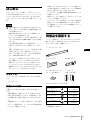
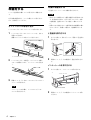
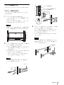
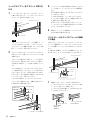
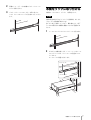
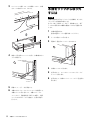
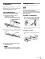
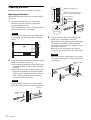
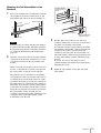
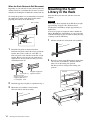
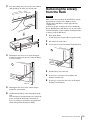
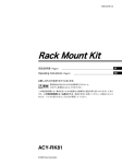
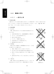
2-634-743-01 (1)
Rack Mounting Kit
取扱説明書 Page 2
______________________________________ JP
Operating Instructions Page 9
_____________________________ GB
お買い上げいただきありがとうございます。
電気製品は安全のための注意事項を守らないと、
火災や人身事故になることがあります。
この取扱説明書には、事故を防ぐための重要な注意事項と製品の取り扱いかたを示してあり
ます。この取扱説明書をよくお読みのうえ、製品を安全にお使いください。お読みになった
あとは、いつでも見られるところに必ず保管してください。
ACY-RKSL
© 2005 Sony Corporation
目次
はじめに ........................................................................................3
必要な工具 ............................................................ 3
設置上のご注意 ..................................................... 3
同梱品を確認する .......................................................................3
準備をする ....................................................................................4
インナーレールを取り出す ................................... 4
本機の準備をする ................................................. 4
ラックの準備をする ............................................. 5
本機をラックに取り付ける ......................................................7
本機をラックから取り外すには .............................................8
© 2005 Sony Corporation. All rights reserved.
商標について
・ Sony、Super Advanced Intelligent Tape は日本およびその他の国におけるソニー株式会社の登録商標または商標で
す。
・ その他、本書に記載されている製品名は各社の登録商標または商標です。
2
はじめに
本ラックマウントキットを使うと、S-AIT ライブラリー
を EIA STANDARD の 19 インチラック(ユニバーサル
ピッチ)に取り付けることができます。取り付けに関し
ては、サービス・サポート窓口までご依頼ください。
(有
償)
ご注意
・
・
・
・
本書に記載されているネジ以外のネジを外さないでく
ださい。落下してけがの原因または機器の損傷につな
がる可能性があります。
本機の質量は約 27 kg(ドライブ 1 台搭載時)です。
(ドライブ 2 台搭載時は約 31 kg)
必ず 2 人以上で作業してください。腰を痛めたり、落
下してけがの原因または機器の損傷につながる可能性
があります。
必ず本機の背面の電源スイッチで電源を切り、ケーブ
ル類をすべて取り外してから、作業を行ってくださ
い。
本機に L 型金具およびインナーレールを取り付ける際
に使用するネジは、必ず、同梱されているネジ A
(B4 × 5)を使用してください。他のネジ類を使用す
ると、本機の故障の原因となります。
ラックのフレーム間の寸法(内寸)が 700 ~ 850
mm の範囲をこえるラックには取り付けできません。
本機はユニバーサルピッチのラックに対応していま
す。ワイドピッチのラックには取り付けできません。
本機側のブラケットは、穴径が φ9 以下または□ 9 以
下のラックフレームには取り付けできません。
必要な工具
・ 本機をラックに取り付けたときに、ラックの重量バラン
スが崩れて転倒することを防ぐため、ラックに転倒防止
金具などを取り付けることをおすすめします。
・ ラック内のすべての機器に電源供給回路が適合すること
を確認してください。
・ 使用するコンセントや電源ケーブルが正しくアースされ
ていることを確認してください。
・ ラックマウントキットを設置しているときに、静電気が
放電しないように作業環境を整えてください。作業中
は、静電防止マットやアースされた静電防止リストバン
ドを使用してください。
同梱品を確認する
パッケージを開けたら、以下のものがそろっているかお
確かめください。付属品の中に欠けているものがあると
きは、お買い上げ店にご連絡ください。
レールアセンブリー(2)
JP
ブラケット(4)
ラック取り付けスペーサー
(4、スペア 2 個含む)
L 型金具(2)
レールガイド
(2 個、左右共通)
ラックマウントキットの取り付けには、次の工具が必要
です。
・ プラスドライバー
ネジブクロ ASSY(A-1127-235)
種類
設置上のご注意
本機をラックに取り付ける前に、以下の点に注意してく
ださい。
・ 本機の動作時に、温度 10 ~ 35 ℃、湿度 20 ~ 80%
を保てる場所に設置してください。室内温度 15 ~ 25
℃の範囲を保てる場所に設置することをおすすめしま
す。
・ 本機前面のカートリッジ挿入 / 排出スロットおよび背面
のファン、通気孔付近に、ケーブルやその他の障害物が
こないように設置してください。
ネジ A(B4 × 5)
ネジ B(PSW5 × 12、
ワッシャー付き)
個数
16
(スペア 2 個含む)
8
(スペア 2 個含む)
ネジ C(B4 × 10)
10
(スペア 2 個含む)
ナット(M4)
10
(スペア 2 個含む)
ブラケット位置決め
ネジ
4
(スペア 2 個含む)
・ 取扱説明書(本書)(1)
はじめに / 同梱品を確認する
3
本機の準備をする
準備をする
L 型金具とインナーレールを本機に取り付けます。
レールと金具類を本機とラックに取り付けて準備をしま
す。
ご注意
レールアセンブリーからインナーレールを取り出します。
・ 体にたまった静電気により部品を破損する場合がありま
す。作業を始める前に、必ず S-AIT ライブラリー本体
の金属部分(塗装されていない部分)に触れてくださ
い。
・ 作業のために指定されている部品以外は内部部品に触ら
ないでください。破損した場合は、有償修理となりま
す。
1
L 型金具を取り付ける
必ず本機の電源を切り、ケーブル類をすべて取り外して
から、作業を行ってください。
インナーレールを取り出す
レールアセンブリーからインナーレールを、止まる
位置まで引き出す。
裏側にロックアームが出てくると止まります。
1
ネジ A を使って、図のようにして、両面に L 型金具を
取り付ける。
2
同様にして、もう一方の側面に L 型金具を取り付け
る。
レールアセンブリーの裏側
ロックアーム
インナーレール
レールアセンブリー
2
レールアセンブリーを裏返し、ロックアームを押し
てロックを解除しながら、インナーレールを引き抜
く。
インナーレールを取り付ける
1
ネジ A を使って、インナーレールを取り付ける。
インナーレール
3
同様にして、もう 1 本のレールアセンブリーからイン
ナーレールを取り出す。
ネジ A
メモ
インナーレールは本機に、レールアセンブリーは
ラックに取り付けます。
4
準備をする
左端の穴に合わせる
2
同様にして、もう一方の側面にインナーレールを取
り付ける。
ラックの準備をする
ブラケット位置決めネジ
ブラケットとレールアセンブリーをラックに取り付けます。
ブラケットを取り付ける
ブラケットのネジ穴が横幅の中心に
来ていることを確認する
2U
レールアセンブリーを固定するためのブラケットをラッ
クに取り付けます。
1
ブラケットを取り付ける位置を決める。
ライブラリー本体とブラケットの位置関係は、以下
のようになります。
各ブラケットを取り付ける位置に、フェルトペンな
どで印を付けておくことをおすすめします。
ご注意
4 個のブラケットの高さを合わせないで本機を取り付
けると、誤動作の原因となりますのでご注意ください。
1U
2U
2U
2
ネジ止め
位置
ブラケット位置決めネジ、ネジ B を使って、前側のブ
ラケット 2 個をラックに取り付ける。
1 ブラケット位置決めネジを使って、ブラケットの
上から 2 番目のネジ穴を止め、ラックにブラケッ
トを取り付ける。
2 ネジ B を使って、ブラケットの下から 2 番目のネジ
穴を止め、ブラケットを固定する。
ブラケットのネジ穴が、ラックの角穴の中央にく
るように合わせてから固定してください。
中心位置に
合わせる
3
ブラケット
ネジ B、ラック取り付けスペーサーを使って、後ろ側
のブラケット 2 個をラックに取り付ける。
ラックの上側の角穴にスペーサーを取り付け、ネジ
B がラックの角穴の横幅の中心にくるようにブラ
ケットを取り付けてください。
ブラケットの向きと高さをまちがえないように気を
つけてください。
ご注意
スペーサーを使用するのは、後ろ側のブラケットの
上側のネジだけです。(スペーサーは、後ろ側のブラ
ケットにのみ取り付けます。)
ラック取り付け
スペーサー
ネジ B
ネジ B
ご注意
ブラケット位置決めネジを使うのは、前側のブラ
ケットの上側のネジだけです。
ブラケット
ブラケット位置
決めネジ
ネジ B
準備をする
5
レールアセンブリーをブラケットに取り付
ける
1
3
スライドレールを手前に最後まで引き出し、ネジ C と
ナットを使って、レールアセンブリーの手前側を止
める。
長穴を使用する場合は、必ず 2 点でレールアセンブ
リーを止めてください。
1 点で止めた場合は、レールアセンブリーがブラ
ケットに対して回転するため、本機を引き出すとき
に支障をきたす場合があります。
両方のブラケットで長穴を使うときは、ラックと
レールアセンブリーの前後の位置をきちんと合わせ
てから、ネジを止めてください。
4
同様にして、もう一方の側面にレールアセンブリー
を左右対称の位置に取り付ける。
レールアセンブリーをブラケットにのせて、ラック
の奥まで差し込み(1)、レールアセンブリーからス
ライドレールを手前に引き出す(2)。
レールアセンブリー
(2)
ブラケット
(1)
スライドレール
スライドレールがラックのフレームに接触
する場合
メモ
スライドレールがラックのフレームに接触して、ス
ムーズに引き出せないときは、「スライドレールが
ラックのフレームに接触する場合」(6 ページ)を参
照し、レールガイドを取り付けてください。
2
ブラケットのネジ穴とレールアセンブリーのネジ穴
を合わせ、ネジ C を使ってレールアセンブリーの後
ろ側を止める。
お使いのラックによっては、ラックのフレームとスライ
ドレールの隙間が少なく、スライドレールがラックのフ
レームに接触して、スムーズに引き出せないことがあり
ます。
その場合は、同梱のレールガイドを前側のブラケットに
取り付けることで、引っかかりを防ぐことができます。
レールアセンブリー
スライドレール
ブラケット
ブラケットの S 部ネジ穴を使うと、ナットが不要に
なりますので、作業がしやすくなります。S 部ネジ
穴が使えない場合は、ナットを使って固定してくだ
さい。
ラックの奥の柱にレールアセンブリーを当てておく
と、位置が決めやすくなります。レールの長さが足
りないときは、ブラケットの長穴を使ってネジを止
めてください。長穴を使用する場合は、必ず 2 点で
レールアセンブリーを止めてください。
1 点で止めた場合は、レールアセンブリーがブラ
ケットに対して回転するため、本機を引き出すとき
に支障をきたす場合があります。
合わないとき
は長穴を使う
S 部ネジ穴
ブラケット
スライド
レール
ラックのフレーム
接触してしまう
ラックのフレーム
1
前側のブラケットにレールガイドを取り付ける。
レールガイドをブラケットのガイドにきちんと寄せ
て、ネジ A(B4 × 5)で固定します。
レールガイドは左右共通です。左右をまちがえない
ように気をつけてください。
ネジ C
ネジ A(B4 × 5)
S 部ネジ穴
レールアセンブリーに当てる
6
準備をする
小さい穴の位置
・ 右側は上
・ 左側は下
ブラケットのガイドに
きちんと寄せる
2
同様にして、もう一方の前側のブラケットにレール
ガイドを取り付ける。
3
ブラケットとレールアセンブリーを取り付ける。
スライドレールがスムーズに引き出せるようになり
ます。
本機をラックに取り付ける
本機をラックに入れて、ブラケットを固定します。
ご注意
本機の質量は約 27 kg(ドライブ1台搭載時)あります。
(ドライブ 2 台搭載時は約 31 kg)
必ず 2 人以上で作業してください。腰を痛めたり、落下
してけがの原因または機器の損傷につながる可能性があ
ります。
1
レールアセンブリーからスライドレールを引き出す。
2
2 人以上で本機を持ち上げ、インナーレールをレール
アセンブリーにのせ、ロックアームの位置までスラ
イドさせる。
ロックアームの位置で止まります。
インナーレール
レールアセンブリー
ロックアーム
本機をラックに取り付ける
7
3
ロックアームを押してロックを解除してから、本機
をラックの奥までスライドさせる。
ロックアーム
本機をラックから取り外
すには
ご注意
本機の質量は約 27 kg(ドライブ1台搭載時)あります。
(ドライブ 2 台搭載時は約 31 kg)
必ず 2 人以上で作業してください。腰を痛めたり、落下
してけがの原因または機器の損傷につながる可能性があ
ります。
4
本機の電源を切る。
背面の電源スイッチで電源を切ってください。
2
ケーブル類をすべて取り外す。
3
両側の L 型金具のファスナーをゆるめる。
4
本機をラックから引き出す。
5
必要に応じて、ラックからレールアセンブリーとブ
ラケットを取り外す。
6
必要に応じて、本機からインナーレールと L 型金具を
取り外す。
前面の L 型金具のファスナーを回し、本機が動かない
ように固定する。
ファスナー
8
1
5
同様にして、もう一方も固定する。
6
本機がきちんとラックに入っていることを確認する。
本機をラックに取り付けたら、本機のクイックス
タートガイド、取扱説明書(PDF)を参照し、電源
ケーブルや SCSI ケーブルを接続し、必要な設定を
行います。
本機をラックから取り外すには
Table of Contents
Introduction ......................................................... 10
Required Tools ................................................. 10
Cautions Concerning Installation ..................... 10
Checking the Package Contents ......................... 10
Preparation .......................................................... 11
Pull Out the Inner Rails .................................... 11
Preparing the Library ....................................... 11
Preparing the Rack ........................................... 12
Mounting the S-AIT Library in the Rack ......... 14
Removing the Library from the Rack ............... 15
GB
© 2005 Sony Corporation. All rights reserved.
Trademarks
• Sony and Super Advanced Intelligent Tape are trademarks of Sony Corporation in this country, other countries, or
both.
• Other product names are trademarks or registered trademarks of their respective owners in this country, other
countries, or both.
9
Introduction
This Rack Mounting Kit can be used to mount the S-AIT
library in an EIA Standard 19-inch rack (Universal
pitch). For installation instructions, contact Sony
Service Support Center. (Charges apply.)
Caution
•
•
•
•
Do not remove any screws other than those indicated
in this manual. Doing so may cause the S-AIT library
to fall, resulting in personal injury or damage to the
S-AIT library.
With a single drive installed, the S-AIT library
weighs approximately 27 kg / 59.5 lbs. (With two
drives installed, the S-AIT library weighs
approximately 31 kg / 68.3 lbs.)
At least two people are needed in order to handle the
library. Handling the S-AIT library on your own
could result in back injury or other accidents
resulting in injury or damage to the S-AIT library.
Before beginning work, always press the power
switch on the rear to turn the power off, and then
disconnect all the cables.
When you install the L-shaped brackets or inner rails
to the library, you must use the supplied A screws (B4
x 5). Using any of the other supplied screws may lead
to damage.
You can install this kit on a frame with 700 to 850 mm
(28 to 34 in.) in internal width. If your rack is larger
than this, you cannot use this kit.
Because the S-AIT library is compatible with
universal pitch racks, you can use this kit on such
racks, but not on wide pitch racks.
You cannot install the S-AIT library side brackets on a
frame with square screw holes or holes smaller than 9
mm (0.4 in.) in diameter.
• When the library is mounted in a rack, the balance of
the rack could be affected and the rack could tip over.
To prevent this from happening, we recommend
securing the rack with brackets that are designed to
keep it from tipping over.
• Confirm that the correct power is being supplied to all
of the equipment in the rack.
• Confirm that the power outlet and power cord that you
are using are properly grounded.
• When installing the Rack Mounting Kit, take all
precautions necessary in order to prevent electrostatic
discharge while work is in progress, including using
anti-static mats and wristbands.
Checking the Package
Contents
After opening the package, make sure that all of the
following items are present. Contact your dealer if
anything is missing.
Rail assembly (2)
Bracket (4)
L-shaped bracket (2)
Rack mounting spacer
(4, 2 spare)
Rail guides
(2, interchangeable)
Required Tools
The following tools are needed in order to mount the
Rack Mounting Kit:
• Philips screwdriver
BAG ASSY SCREW (A-1127-235)
Cautions Concerning Installation
Check the following points before mounting the S-AIT
library in a rack.
• Install the library in an operating environment with a
temperature range of 10 to 35 °C, and a humidity
range of 20 to 80 %. We recommend installing the
library in an indoor location where the temperature is
maintained between 15 and 25 °C.
• When installing the library, keep cables and other
obstructions away from the area around the import/
export slot on the front and the fan and the ventilation
holes on the rear of the library.
10
Introduction / Checking the Package Contents
Type
Quantity
A screw (B4 × 5)
16 (2 spare)
B screw (PSW5 × 12,
with washer)
8 (2 spare)
C screw (B4 × 10)
10 (2 spare)
Nut (M4)
10 (2 spare)
Bracket positioning
screw
4 (2 spare)
• Operating Instructions (this manual)
Preparing the Library
Preparation
In order to mount the S-AIT library, first mount the rails
and brackets on the library and rack.
Mount the L-shaped brackets and inner rails on the
library.
Caution
Before beginning work, always be sure to turn off the SAIT library, and then disconnect all cables.
Pull out the inner rails from the rail assemblies.
• Electrostatic charges that build up on your body can
damage the components. Before starting work, touch
the metal chassis of the S-AIT Library.
• Do not touch any components other than those that
must be replaced. In the event of damage, a charge will
be assessed for repair.
1
Mounting the L-shaped Brackets
Pull Out the Inner Rails
Pull out the inner rail from one of the rail
assemblies as far as it will go.
The rail can be extended until the locking arm on
the back of the rail emerges.
1
Use two A screws to mount an L-shaped bracket on
the side of the library as shown in the diagram.
2
Mount the L-shaped bracket on the other side of the
library in the same manner.
Back of rail assembly
Locking arm
Inner rail
Rail assembly
2
Turn the rail assembly over. Press the locking arm
to release the lock, and then pull the inner rail all of
the way out.
Mounting the Inner Rails
1
Use four A screws to mount an inner rail on the
library.
Inner rail
A screw
Position of screw hole on the left side
3
Repeat the process with the other rail assembly,
pulling out its inner rail.
2
Mount the other inner rail on the other side of the
library in the same fashion.
Note
The inner rail will be mounted on the S-AIT library,
while the rail assembly will be mounted on the rack.
Preparation
11
Preparing the Rack
Bracket positioning screw
Mount the brackets and rail assemblies on the rack.
Mounting the Brackets
Make sure that the bracket screw
holes are centered horizontally.
2U
Mount the brackets that hold the rail assemblies in place
on the rack.
1
Position
of screw
cramps
Decide where the brackets are to be mounted.
The library position in relation to the bracket
position is explained below.
We recommend using a marker to mark the position
where each bracket is to be mounted.
Center the
screw holes
Bracket
Caution
Note that if the four brackets are not mounted at the
correct height, it will be impossible to mount the
library.
1U
2U
3
Using the B screws and rack mounting spacers,
mount the two rear brackets on the rack.
First align the rack mounting spacers with the upper
part of the rack screw holes, then center the B
screws on the rack screw holes, and finally secure
the brackets to the rack.
Make sure that all four brackets are facing the
correct way and are mounted at the correct height.
2U
Caution
2
Using the bracket positioning and B screws, mount
the two front brackets on the rack.
1 Insert a bracket positioning screw into the second
screw hole from the top of the bracket and tighten
it slightly.
2 Insert a B screw into the second screw hole from
the bottom of the bracket and tighten it slightly.
Align the screws with the center of the rack screw
holes, and then tighten the screws completely,
securing the bracket to the rack.
Caution
Use the bracket positioning screws only with the
upper part of the screw holes on the front brackets.
Bracket
Bracket positioning
screw
B screw
12
Preparation
Only use the spacers with the upper screws on the
rear brackets. (The spacers are only used with the
rear brackets.)
Rack mounting
spacer
B screw
B screw
Mounting the Rail Assemblies on the
Brackets
1
Use this slot if the
screw holes do not
line up.
Place a rail assembly in one set of brackets, slide the
rail assembly all of the way into the rack (1), and
then pull the slide rail out of the rail assembly (2).
S screw hole
C screw
Rail assembly
(2)
Bracket
S screw hole
(1)
Rail assembly flush
against rack post
Slide rail
Note
3
Pull the slide rail all of the way out of the rail
assembly, and then use a C screw to secure the front
end of the rail assembly to the bracket.
If you decide to use the elongated holes to fasten the
rail assembly to the bracket, you must fasten the rail
assembly in two points. If you fasten the rail
assembly in only one point, the rail assembly can
turn on the bracket, which may lead to damage and/
or injury when pulling out the S-AIT library from
the rack.
If you use the slots for fastening, be sure to
carefully align the rack and the rail assembly before
tightening the screws.
4
Mount the rail assembly on the other side in the
same manner.
If the rail comes in contact with the rack and does
not slide in and out smoothly, install the rail guides.
For information about how to install the rail guides,
see “When the Rack Obstructs Rail Movement”
(page 14).
2
Align the screw holes in the rail assembly with the
screw holes in the brackets, and then use a C screw
to secure the back end of the rail assembly to the
bracket.
When you use the S screw holes you do not need to
use nuts, so installation is easier. If you cannot use
the S screw holes, secure the screws with nuts.
The position is easy to determine if you push the
rail assembly all of the way into the rack so that it
is touching the post in the back of the rack. If the
screw holes do not line up, use the slot to the side of
the round screw hole to fasten the rail assembly to
the bracket. If you decide to use the elongated holes
to fasten the rail assembly to the bracket, you must
fasten the rail assembly in two points. If you fasten
the rail assembly in only one point, the rail
assembly can turn on the bracket, which may lead
to damage and/or injury when pulling out the
S-AIT library from the rack.
Preparation
13
When the Rack Obstructs Rail Movement
Depending on your rack, the clearance between the rack
and the rail may be so small that the rail comes in contact
with the rack, making the rail difficult to slide in and out.
To remedy this problem, we recommend that you install
the supplied rail guides on the front brackets when
preparing the rack for the S-AIT library.
Rail assembly
Slide rail
Bracket
Bracket
Slide rail
Rack
Rack
1
Mounting the S-AIT
Library in the Rack
Insert the library into the rack, and then secure the
brackets.
Caution
With a single drive installed, the S-AIT library weighs
approximately 27 kg/59.5 lbs. (With two drives
installed, the S-AIT library weighs approximately 31
kg/68.3 lbs.)
At least two people are needed in order to handle the
library. Handling the S-AIT library on your own could
result in back injury or other accidents resulting in injury
or damage to the S-AIT library.
1
Pull the straight rails out from the rail assemblies.
2
Have two or more people lift the library, fit the inner
rails into the rail assemblies, and then slide the
inner rails to the locking arm position.
The library will not slide past the locking arm
position.
Obstruction
Install the rail guides on the front brackets.
Install the rail guide so that it fits snugly against the
bracket, then secure it with a A screw (B4 × 5).
Each rail guide can be installed on the left or right
bracket. However, because the rail guides have a
slight bend at one end, make sure that you do not
install them inside out.
A screw (B4 × 5)
Rail guide snugly fitted
against the bracket
Inner rail
Small hole position
(relative to the screw hole)
• Right rail guide: above
• Left rail guide: under
14
2
Install the opposite rail guide as explained in step 1.
3
Mount the rail assemblies on the brackets.
The rails slide in and out smoothly.
Mounting the S-AIT Library in the Rack
Rail assembly
Locking arm
3
Press the locking arm to release the lock, and then
slide the library all of the way into the rack.
Locking arm
Removing the Library
from the Rack
Caution
With a single drive installed, the S-AIT library weighs
approximately 27 kg/59.5 lbs. (With two drives
installed, the S-AIT library weighs approximately
31 kg/68.3 lbs.)
At least two people are needed in order to handle the
library. Handling the S-AIT library on your own could
result in back injury or other accidents resulting in injury
or damage to the S-AIT library.
4
1
Turn off the library.
To turn the power off, press the rear power switch.
2
Disconnect all of the cables.
3
Loosen the screws in both of the L-shaped brackets.
4
Pull the library out of the rack.
5
If necessary, remove the rail assemblies and
brackets from the rack.
6
If necessary, remove the inner rails and L-shaped
brackets from the library.
Hand tighten the screw on one of the L-shaped
brackets on the front of the rack so that the library
is secured in place.
Fastener
5
Hand tighten the screw on the other L-shaped
bracket the same manner.
6
Confirm that the library is housed properly in the
rack.
Once the library is mounted in the rack, connect the
power cord and the SCSI cables and make all
necessary settings as described in the Quick Start
Guide and Operating Instructions (PDF).
Removing the Library from the Rack
15
For contact information, refer to the Quick Start Guide for the S-AIT Library.
Printed in Japan