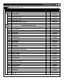
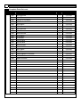
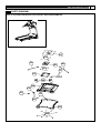
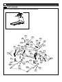
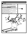
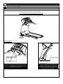
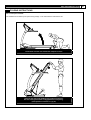
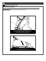
1
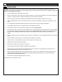
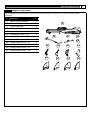
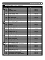
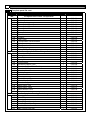
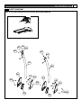
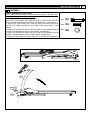
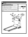
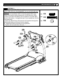
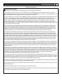
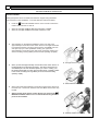
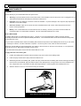
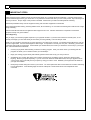
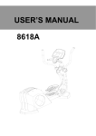
USER’S MANUAL
5.25E MOTORIZED TREADMILL
MODEL NUMBER: 5.25E
USER WEIGHT LIMITATION: 125 (275lbs)
SERVICE NUMBER: 0800-09 72 100
SERIAL NUMBER (found on frame):
2
PRECAUTIONS
WARNING: To reduce the risk of burns, fire, electric shock, or injury to persons, read the following important precautions and
information before operating the treadmill. It is the responsibility of the owner to ensure that all users of this treadmill are adequately
informed of all warnings and precautions.
•
Use the treadmill only as described in this manual.
•
Place on a level surface, with 6 feet (2 m) of clearance behind it. Do not place the treadmill on any surface that blocks air
openings. To protect the floor or carpet from damage, place a mat under the treadmill.
•
When choosing a location for the treadmill make sure that the location and position permit access to a plug.
•
Keep the treadmill indoors, away from moisture and dust. Do not put the treadmill in a garage or covered patio, or near
water.
•
Do not operate the treadmill where aerosol products are used or where oxygen is being administered.
•
Keep children under the age of 12 and pets away from the treadmill at all times.
•
The treadmill should not be used by persons weighing more than 125 kgs (275lbs)
•
Never allow more than one person on the treadmill at a time. Wear appropriate exercise clothing when using the treadmill.
Do not wear loose clothing that could become caught in the treadmill. Athletic support clothes are recommended for both
men and women. Always wear athletic shoes. Never use the treadmill with bare feet, wearing only stockings, or in
sandals.
•
When connecting the power cord, plug the power cord into a grounded circuit. No other appliance should be on the same
circuit.
•
Always straddle the belt and allow it to start moving before stepping onto the belt.
•
Always examine your treadmill before using to ensure all parts are in working order.
•
Allow the belt to fully stop before dismounting.
•
Never insert any object or body parts into any opening.
•
Follow the safety information in regards to plugging in your treadmill.
•
Keep the power cord away from the incline wheels and do not run the power cord underneath your treadmill. Do not
operate the treadmill with a damaged or frayed power cord.
•
Always unplug the treadmill before cleaning and/or servicing. Service to your treadmill should only be performed by an
authorized service representative, unless authorized and/or instructed by the manufacturer. Failure to follow these
instructions will void the treadmill warranty.
•
Never leave the treadmill unattended while it is running.
The equipment is for Class B (Home Use).
www.smoothfitness.co.uk
3
POWER REQUIREMENTS
IMPROPER CONNECTION OF THE EQUIPMENT GROUNDING CONNECTOR CAN RESULT IN A RISK OF AN ELECTRIC
SHOCK. CHECK WITH A QUALIFIED ELECTRICIAN OR SERVICE MAN IF YOU ARE IN DOUBT AS TO WHETHER THE
PRODUCT IS PROPERLY GROUNDED. DO NOT MODIFY THE PLUG PROVIDED WITH THE PRODUCT, IF IT WILL NOT FIT
THE OUTLET; HAVE A PROPER OUTLET INSTALLED BY A QUALIFIED ELECTRICIAN.
This treadmill can be seriously damaged by sudden voltage changes in your home’s electrical power. Voltage spikes, surges and
noise interference can result from weather conditions or from other appliances being turned on or off. To reduce the possibility of
treadmill damage, always use a surge protector (not included) with your treadmill. Surge protectors can be purchased at most
hardware stores.
This treadmill is provided with two different grounding plugs for Central Europe and United Kingdom. Please choose the right one
and plug in your treadmill.
Please make sure that your local voltage is appropriate for the power requirements of this treadmill before you plug it in.
This product is for use with a voltage of 230V+ 5%.
GFCI outlets and GFCI Circuit Breakers are NOT recommended for use on this product. GFCI outlets and GFCI Circuit Breakers
may cause this equipment to improperly function
Do not use a voltage transformer with this product.
Do not use an extension cord with this product when you are not sure if the product is still properly grounded.
The following pictures show the two delivered plugs:
4
PREASSEMBLY
Open the boxes:
Open the boxes of your new equipment. Inventory all parts included in the boxes. And Compare them to the supplied components
and supplied Hardware lists on pages 5-6 for a full count of the parts included . If you are missing any parts or have any assembly
questions contact us directly at 0800-09 72 100 .
Assembly instructions begin on page 18
Gather your tools:
Before starting the assembly of your unit, make sure that you have gathered all the necessary tools you may require to assemble
the unit properly. Having all of the necessary equipment at hand will save time and make the assembly quick and hassle-free.
Clear your work area:
Make sure that you have cleared away a large enough space to properly assemble the unit. Make sure the space is free from
anything that may cause injury during assembly. After the unit is fully assembled, make sure there is a comfortable amount of free
area around the unit for unobstructed operation.
Invite a friend:
Some of the assembly steps may require heavy lifting. It is recommended that you obtain the assistance of another person when
assembling this product.
User Weight Limitation:
Please note that there is a weight limitation for this product. If you weigh more than 125 LBS (Approx. 275 Kg). it is not
recommended that you use this product. Serious injury may occur if the user’s weight exceeds the limit shown here. This
product is not intended to support users whose weight exceeds this limit.
Care and maintainence:
1.
The safety level can be maintained only if it is examined for damage and wear.
2.
Replace any defect components immediately and stop to use the equipment until repaired.
3.
Always take care when you mounting the equipment . Straddle the equipment by placing your feet on the straddle rails . .
Dismount from the equipment only after all parts have stopped.
4.
Always check the easily wear components like pulley ets. To prevent danger.
5.
There is an emergency stop to prevent dangers, you can stop the treadmill immediately by actuated the emergency stop for
emergency dismount.
www.smoothfitness.co.uk
Supplied components
This list identifies the major components you will use to assemble this product. Component A , B and C are already partially
assembled .
No.
Description
Qty.
A
Main Frame Assembly
1
B
Front handlebar
1
C
Side handle bar
2
108 Water Bottle Holder
2
207 Handle Bar Cover - LL
1
208 Handle Bar Cover - LR
1
209 Handle Bar Cover - RL
1
210 Handle Bar Cover - RR
1
302 Upright Base Cover - LL
1
303 Upright Base Cover - LR
1
304 Upright Base Cover - RL
1
305 Upright Base Cover - RR
1
A
C
B
207
302
208
303
108
209
210
304
305
5
6
Supplied Hardware
This list identifies the hardware you will use to assemble the product . To help distinguish between the various types of the screw
and bolts, use the scale below to measure them and compare them to the size listed .
No.
Description
Qty.
802 M4×15 Screw
805 M8×45 Bolt
27
810 M8×18 Bolt
8
811 M8×52 Bolt
2
812 φ8 Washer
12
845 M8×75 Bolt
A Screw driver
2
805
802
810
811
2
1
B
Allen key
1
C
Allen Wrench
1
D
Safety Key
1
E
Power Cord
2
845
812
A
B
D
MILLIMETERS
C
E
www.smoothfitness.co.uk
Complete Computer Console Components
Description
100
101
102
103
104
105
106
107
108
109
110
111
200
201
202
203
204
205
206
207
208
209
210
211
212
213
214
215
216
217
300
301
302
303
304
305
306
307
308
309
Qty.
Order No.
1
1
1
1
1
1
1
2
2
8
2
5.25-101
5.25-102
5.25-103
5.25-104
5.25-105
5.25-106
5.25-107
5.25-108
5.25-109
5.25-110
5.25-111
1
2
2
2
1
2
1
1
1
1
1
1
2
2
2
2
2
5.25-201
5.25-202
5.25-203
5.25-204
5.25-205
5.25-206
5.25-207
5.25-208
5.25-209
5.25-210
5.25-211
5.25-212
5.25-213
5.25-214
5.25-215
5.25-216
5.25-217
2
1
1
1
1
2
2
1
1
5.25-301
5.25-302
5.25-303
5.25-304
5.25-305
5.25-306
Console Assembly
Overlay
Computer PC Board
Console Plate
Console Housing - Upper
Console Housing - Bottom
Safety Key Base
Safety Key
Water Bottle Holder
Motion Control Sensor Wire - Upper
Plastic Fixing Insert
Hand Pulse Wire - Upper
Complete Handle Bar Components
Front Handle Bar Tube
Handle Bar
Handle Bar Upright Foam Grip
Handle Bar Upright Foam Grip
Handle Bar Upright Foam Grip
Hand Pulse Sensor
Handle Bar Cover - LL
Handle Bar Cover - LR
Handle Bar Cover - RL
Handle Bar Cover - RR
Console Connect Piece - L
Console Connect Piece - R
Console Connect Tube
Motion Control Sensor
Motion Control Sensor Base
Handle Bar End Cap
Hand Pulse Wire - Lower
Complete Upright Components
Upright
Upright Low Covre - LL
Upright Low Covre - LR
Upright Low Covre - RL
Upright Low Covre - RR
Adjustable Cylinder Cover - Upper
Motion Control Sensor Wire - Middle
2 pin Safety Key Wire 2200 mm
7 pin Computer Wire – Upper 2980mm
5.25-307
5.25-308
5.25-309
7
8
Complete parts list cont.
400
401
402
403
404
405
406
407
408
409
410
411
412
413
414
415
416
500
501
502
503
504
505
506
507
508
509
510
511
512
513
514
515
516
517
518
519
600
601
602
603
604
605
606
607
Description
Complete Base Frame Components
Base Frame
Rubber Cushion
Rubber Cushion
Power Switch Plate Base
Power Switch Plate Cover
Power Switch Plate
Power Breaker
Power Switch
Front Caster
Cushion
Foot Locker
Transportation Wheel Bracket
Spring
Transportation Wheel
Fold Up Locker
Spring Of The Fold Up Locker Assembly
Complete Motor Components
Motor Hood Top
Driving Motor
Motor Holder
Driving Belt
Control Board
Elevation Support Tube
Elevation Support Tube End Cap
Elevation Motor
Elevation Gear Sleeve
Fold Up Support
Shock
Wheel
Plastic Clamp - Top
Plastic Clamp - Bottom
Elevation Support
Motor Hood - Left
Motor Hood - Right
Motor Bottom Cover
Relay board
Complete Running Deck Components
Running Belt
Side Rail
Running Deck
Side Rail End Cap - Left
Side Rail End Cap - Right
Cushion Pad
Main Frame Cross Bar
Qty.
Order No.
1
2
2
1
1
1
1
1
2
2
1
1
1
1
1
1
5.25-401
5.25-402
5.25-403
5.25-404
5.25-405
5.25-406
5.25-407
5.25-408
5.25-409
5.25-410
5.25-411
5.25-412
5.25-413
5.25-414
5.25-415
5.25-416
1
1
1
1
1
1
4
1
1
1
1
1
2
2
2
1
1
1
1
5.25-501
5.25-502
5.25-503
5.25-504
5.25-505
5.25-506
5.25-507
5.25-508
5.25-509
5.25-510
5.25-511
5.25-512
5.25-513
5.25-514
5.25-515
5.25-516
5.25-517
5.25-518
5.25-519
1
2
1
1
1
8
1
5.25-601
5.25-602
5.25-603
5.25-604
5.25-605
5.25-606
5.25-607
www.smoothfitness.co.uk
Complete parts list cont.
No.
700
701
702
703
704
705
706
707
800
801
802
803
804
805
806
807
808
809
810
811
812
813
814
815
816
817
818
819
820
821
823
824
825
826
827
828
829
Description
Complete Deck Frame Components
Deck Frame
Front Roller Shaft
Front Roller Tube
Rear Roller Shaft
Rear Roller Tube
Running Deck Rear wheel
Cushion Pad
Qty.
Order No.
1
1
1
1
1
2
6
5.25-701
5.25-702
5.25-703
5.25-704
5.25-705
5.25-706
5.25-707
8
49
2
4
2
4
4
4
1
8
4
5.25-801
5.25-802
5.25-803
5.25-804
5.25-805
5.25-806
5.25-807
5.25-808
5.25-809
5.25-810
5.25-811
5.25-812
5.25-813
5.25-814
5.25-815
5.25-816
5.25-817
5.25-818
5.25-819
5.25-820
5.25-821
5.25-823
5.25-824
5.25-825
5.25-826
5.25-827
5.25-828
5.25-829
Complete Hardware Pack
M3.5×16 Screw
M4×15 Screw
M3×10 Screw
φ4 Washer
M8×45 Bolt
M4×8 Screw
M5×30 Screw
M3×14 Screw
M8×49 Bolt
M8×18 Bolt
M8×52 Bolt
φ8 Washer
M4×25 Screw
Transportation Wheel Bolt
φ5 Washer
M5×10 Screw
M4×14 Screw
M10 Nylon Nut
M10×67 Bolt
φ14×50 Bolt
φ33×φ8×10 Screw
φ4×45 Screw
M10×116 Screw
φ8 Nylon Nut
M8×12 Bolt
φ8 Washer
φ10 Washer
φ14 Clip
22
2
3
3
3
3
7
2
2
2
2
1
2
2
2
4
2
9
10
Complete Parts list cont .
No.
Description
Qty.
Order No.
830
M8×48 Screw
1
5.25-830
831
M8×85 Screw
1
5.25-831
832
φ26×φ8.5×3 Washer
2
5.25-832
833
φ25 Rubber Cushion
1
5.25-833
834
M8×30 Bolt
4
5.25-834
835
M5×14 Screw
4
5.25-835
836
M4×19 Screw
16
5.25-836
837
M3×8 Screw
2
5.25-837
838
M8×23 Screw
6
5.25-838
839
M6×45 Bolt
3
5.25-839
840
φ6 Washer
3
5.25-840
841
M10×33 Bolt
1
5.25-841
842
M10×56 Bolt
2
5.25-842
843
M8×36.5 Bolt
1
5.25-843
844
M10×43.5 Bolt
1
5.25-844
845
M8×75 Bolt
2
5.25-845
846
M8×30 Screw
2
5.25-846
847
3MM RUBBER CUSHION
2
5.25-847
848
M10×26 Bolt
2
5.25-848
849
M8x20 mm Bolt
1
5.25-849
www.smoothfitness.co.uk
PARTS DIAGRAM
MOST OF THE PARTS SHOW HERE HAVE ALREADY BEEN PRE-ASSEMBLED.
101
801
109
102
801
109
111
103
108
104
106
107
110
803
105
802
11
12
PARTS DIAGRAM
MOST OF THE PARTS SHOW HERE HAVE ALREADY BEEN PRE-ASSEMBLED.
805
845
203
805
217
206
812
207
201
806
203
812
217
804
211
808
802
802
845
205
808
212
209
807 208
210
806
802
802
213
214
202
215
214
810
807
215
213
812
204
802
804
204
812
216
810
www.smoothfitness.co.uk
PARTS DIAGRAM
MOST OF THE PARTS SHOW HERE HAVE ALREADY BEEN PRE-ASSEMBLED.
307
308
309
807
307
807
301
301
302
110
303
304
802
110
802
305
802
306
306
13
14
PARTS DIAGRAM
MOST OF THE PARTS SHOW HERE HAVE ALREADY BEEN PRE-ASSEMBLED.
811
837
812 810
812
814 409
406 813
812 810
815
816
812
811
408
407
405
416
812
404
849
415
815
809
403
825
414
843
844
402
401
412
411
410
403
413
818
802
802
402
802
802
410
409 814
www.smoothfitness.co.uk
PARTS DIAGRAM
MOST OF THE PARTS SHOW HERE HAVE ALREADY BEEN PRE-ASSEMBLED.
823
501
817
820
828
848
511
507
816 819
815
502
505
507 818
829
506
829 819
509
512 821
507
818
814510
831
827
513
820
802
828
514
515
516
504
812
834
818
513
514
515
812
517
518
802
833
503
508
507
821
824
812 826 832
825
802
834
830
825
832
15
16
PARTS DIAGRAM
MOST OF THE PARTS SHOW HERE HAVE ALREADY BEEN PRE-ASSEMBLED.
602
604
602
605
835
835
601
836
836
606
606
836 846
838
836
836
606
838
838
606
838
846
603
847
607
www.smoothfitness.co.uk
PARTS DIAGRAM
MOST OF THE PARTS SHOW HERE HAVE ALREADY BEEN PRE-ASSEMBLED.
703
702
704
705
840
707
848
828
839
840
701
828
818
842
828
706
842
839
818
841
17
18
ASSEMBLY
STEP 1: Unpacking and Inventory
NOTE: FOR SAFER AND EASIER TRANSPORTATION DO NOT REMOVE
THE PLASTIC RETAINING STRAPS UNTILL THE UNIT IS IN THE AREA OF
ASSEMBLY
Remove the treadmill and all the components and hardware from the box. Check
the quantities of all components and hardware with the component and hardware
lists on pages 5-6
P.5
Components
P.6
Hardware and
tools
www.smoothfitness.co.uk
ASSEMBLY
STEP 2: Assemble Upright Frame
NOTE : Make sure all wires are recessed into the frame , DO NOT trap
or pinch (Hand tight bolts until last step )
A) Raise the left and right uprights (301 X 2 ) .
B) Secure the left upright (301) with two 8x18 mm Allen bolts (810) and
two # 8 washer through the front side of the base frame . hand tighten .
C) Secure the right upright (301) with two 8x18 mm Allen bolts (810)
and two # 8 washer through the front side of the base frame . hand
tighten .
D) Insert one M 8x52 mm Allen bolt (811) and one # 8 washer through
the side of the base frame and the left upright , hand tighten .
E) Insert one M 8x52 mm Allen bolt (811) and one # 8 washer through
the side of the base frame and the right upright , hand tighten .
F) Tighten all Allen bolts with Allen wrench C (Provided with hardware).
811
X2
810
X4
812
X6
f ig -1
301
810
812
811
812
19
20
ASSEMBLY
STEP 3: Assemble Front Handle Bar
NOTE : Only hand tighten bolts until last step.
A) Place the front handle bar (201) on top of the left and right
upright (301).
B) Secure left side with one # 8 washer (812) and M8x45 mm
Allen bolt (805) in the forward most hole .
C) Secure right side with one # 8 washer (812) and M8x45 mm
Allen bolt (805) in the forward most hole .
D) Connect pulse wire (217) and wire (111) on left and right side
(as shown in diagram) . Then insert the remaining length of the
wire into the front handle bar tube . Tighten all bolts with Allen
Wrench .
805
X2
812
X2
www.smoothfitness.co.uk
ASSEMBLY
STEP 4: Assemble The Side Handlebars
NOTE: Side rails are interchangeable for use on both right and
left sides
A ) Attach one handlebar (202) to the left upright (301),and
connect the motion control sensor wire (214) and wire (109).
B) Secure the Side Handlebar with one M8 x75 mm bolt (845)
and one # 8 washer , through the top of front handle bar into the
side handle bar .
C) Insert two M8x18 mm (810) and two # 8 washer through the
side handrail plate and thread into the upright .
D) Repeat the above process for the right side .
E) Tighten all bolts with Allen Wrench .
810
X4
845
X2
812
X6
21
22
ASSEMBLY
STEP 5: Assemble Computer Console
A) Rotate the console until it stops as shown in diagram
below .
B) Tighten the screw (807) of the console connect tube (213)
for right and left side . Console connect tube (213) will be
adjust for the next steps of assembly .
C) Attach the Handle Bar Cover - LR (208) to the underside of
the console and the inside of the left upright (301), Secure with
four M4×15mm screw (802). And secure with two M4×15mm
screw (802) between the Handle Bar Cover - LR (208) outside
and the console housing -upper.
D)Attach the Handle Bar Cover - LL (207) to the top of the
console and the outside of the Upright - Left (301).And secure
with four M4×15mm screw (802).
E) Repeat the above process for the right hand side cover
(209) and cover (210) as shown in diagram.
802
X20
www.smoothfitness.co.uk
ASSEMBLY
STEP 6: Assembly base covers
NOTE : Refer to folding instructions on page 27 .
A) Fold up the running deck until it locks in place .
B) Attach Upright Base Cover (302) to the outside of the Left
Upright (301). Secure with two M4x15 mm screw (802).
C) Attach Upright Base Cover (303) to the inside of the Left
Upright (301). Secure with one M4x15 mm screw (802).
D) Attach Upright Base Cover (305) to the outside of the Right
Upright (301). Secure with three M4x15 mm screw (802).
E) Attach Upright Base Cover (304) to the inside of the Right
Upright (301). Secure with one M4x15 mm screw (802).
802
X7
23
24
ASSEMBLY
STEP 7: Attaching Rubber Cover
Insert the rubber cover (306) into the slot upright base cover .
www.smoothfitness.co.uk
ASSEMBLY
STEP 8: Inserting Water Bottle Holders
Attach the Water Bottle Holder(108)to the Console Housing
- Upper(104)and push down until snap in place.
25
26
ASSEMBLY COMPLETE
Assembly is now complete. Check that all the components are secure and all the hardware is tight . By this step all bolts and
screws should be wrench tight. If any hardware is not wrench tight go back and tighten.
The finished product should resemble the picture below.
Safety Features
The safety key must be inserted for the treadmill to
function. The safety key tether should be worn at all
times when the treadmill is in use. This safety feature
is designed to prevent injury.
There are two orange levers on this treadmill.
The most forward lever is the folding lock
which is used in folding and unfolding this
treadmill. The other is used for transporting
from one location to another.
www.smoothfitness.co.uk
FOLDING INSTRUCTIONS
How to fold up the treadmill:
Your treadmill can be folded up for space saving storage. To do this follow the instructions here:
Lift the deck from the rear towards the computer console.
Listen for the click of the Folding Level locking mechanism .
Be sure locking mechanism is engaged before transporting .
(Transportation instruction on pg 30 )
27
28
UNFOLDING INSTRUCTIONS
How to unfold the treadmill:
NOTE: To maintain stability make sure the rear transportation wheel is disengaged before
unfolding treadmill
To unfold the treadmill for use follow the instructions here:
Release Lever
Push the deck towards the computer console .
Depress the Folding Level begin lowering the treadmill
towards the floor release the folding level .
Lower treadmill deck towards floor .
www.smoothfitness.co.uk
TRANSPORT INSTRUCTIONS
TRANSPORT INSTRUCTIONS:
NOTE: Transport wheel must be down as picture below.
To roll away for storage simply grab the rear deck, lift slightly and roll to desired location.
Lift the deck from the rear so that the treadmill rests on the
front transportation wheels and on the rear transportation wheel engages
Roll to a desired location.
29
30
COMPUTER OPERATION
GA B C
D EF
START Button
A
B
INCLINE UP/DOWN Buttons
Safety Key
C
D
SPEED UP/DOWN Buttons
STOP/ENTER Button
E
F
Display Window
Motion Control Button
G
BUTTON FUNCTIONS
START – Press to start exercise at initial speed 0.5MPH / 0.8KPH.
STOP / ENTER
a. Press to confirm program and preset function values setting mode.
b. Press to run setting procedure before pressing the START KEY.
c. Press to stop exercise during workout time.
SPEED UP
a. Press to increase exercise speed by 0.1MPH/KPH.
b. Hold the button to rapidly increase speed by 0.5MPH/KMPH per second and release the button to stop the function.
SPEED DOWN
a. Press to decrease exercise speed by 0.1MPH/KPH.
b. Hold the button to rapidly decrease speed by 0.5MPH/KMPH per second and release the button to stop the function.
INCLINE UP / DOWN
a. Press up or down to change incline level.
b. Press to select programs and preset related function value.
SAFETY KEY
The safety key must be inserted into the slot on the console in order to operate the treadmill. Always insert the safety key and
attach the clip to your clothing at your waist before beginning your workout. If you should encounter problems and need to stop the
motor quickly, simply pull on the cord to disengage the safety key from the console. To continue operation first turn the power
switch to off and set the speed controller to stop. Next turn the power switch to on and reinsert the safety key into the console.
www.smoothfitness.co.uk
31
COMPUTER OPERATION
POWER ON
Set the POWER SWITCH, located on the base frame, to ON and insert the SAFETY KEY. The UPPER LCD and LOWER LCD
screens light up all digits and enter the POWER ON mode.
The LOWER LCD SPEED/DISTANCE window shows “0.0” and 6 programs LED lights blink individually.
The UPPER LCD shows 0 on all windows.
SLEEP MODE
When the power is ON the computer will automatically enter SLEEP MODE if it is left idle for 3 minutes without receiving any input.
Press any button to return to POWER ON status when the computer is in the SLEEP MODE.
DISPLAY MODE
This feature is designed only for store display purpose. To cancel the SLEEP MODE feature, pull out the safety key, press and
hold the SPEED UP and DOWN buttons, insert the safety key to power on the treadmill. After one short beep sound, the SLEEP
MODE will be cancelled and the LCD will not go off as long as the power switch stays on and the safety key is inserted properly.
ENGLISH / METRIC CONVERSION
The computer has been preset to calculate and show all information in English (miles, pounds, and inches). The computer can be
set to display information in Metric (kilometers, kilograms, centimeters). To do this set the POWER SWITCH, located on the base
frame, to ON. Press and hold the START button. Insert the SAFETY KEY. The computer will sound one short BEEP and the
UPPER LCD will show KM and blink. Press the INCLINE UP/DOWN button to switch between KM and ML. KM means Metric and
ML means English. Press the STOP/ENTER button to confirm the setting and return to POWER ON status after one long beep
sound.
QUICK START
When the treadmill is in POWER ON status, press the START button to activate the QUICK START. The SPEED LCD counts down
3 seconds with 3 short beeps then starts from 0.5 MPH/0.8 KPH. Press the SPEED UP/DOWN buttons to adjust the speed. Press
the INCLINE UP/DOWN buttons to elevate the treadmill. The TIME, CALORIES and DISTANCE count up from 0. The PULSE LCD
shows P until you hold the hand pulse grip sensors then the PULSE LCD will display the current pulse during the workout.
STOP/PAUSE
During the workout, press the STOP/ENTER button to PAUSE the treadmill, all workout data will be frozen. Press the START
button to resume the workout and all data will continue counting. If the STOP/ENTER button is pressed twice, the treadmill will
return to POWER ON status and all workout information will return to 0.
COMPUTER PROGRAM OPERATION
To select the program, press the program buttons when the treadmill is in POWER ON status. For the first time user, you have to
set up the user information and assign your USER ID from U 1 to U 9 before the program starts.
SET UP USER INFORMATION
Press any program button on the computer panel. For the first time use of the treadmill, the LCD will show a blinking U1 and the
LCD will show factory default setting values of user weight, height, age and target heart rate. Press the INCLINE UP/DOWN
buttons to choose the USER ID from U1 to U9 and press the STOP/ENTER button to assign your
user ID.
SET USER GENDER
After assigning your user ID, the gender icon will display on the LCD. Press the INCLINE UP/DOWN buttons to switch between
male and female icon then press the STOP/ENTER button to select your gender.
SET USER WEIGHT
After setting the user gender, the LCD will display W. The TIME LCD display now shows the blinking factory setting user weight
150LB/68KG. Press the INCLINE UP/DOWN buttons to adjust the user weight correctly and press STOP/ENTER to set the user
weight.
32
COMPUTER OPERATION
SET USER HEIGHT
After setting the user weight, the LCD will display H. The CALORIES LCD display now shows the blinking factory setting user
height 67”/170CM. Press the INCLINE UP/DOWN buttons to adjust the user height correctly and press STOP/ENTER to set the
user height.
SET USER AGE
After setting the user height, the LCD will display A. The INCLINE LEVEL LCD display now shows the blinking factory setting user
age 35. Press the INCLINE UP/DOWN buttons to adjust the user age correctly and press STOP/ENTER to set the user age. When
you set up the user AGE, please note the user TARGET HEART RATE will be adjusted with the user AGE according to the factory
setting.
SET USER TARGET HEART RATE
The factory TARGET HEART RATE setting is based on 85% of the maximum heart rate. The maximum heart rate is calculated as
220 minus the user age. For age 35, the maximum user heart rate should be 185 and 85% of user heart rate, which is 157. After
setting the user age, the LCD will show P and the PULSE LCD shows the blinking factory target heart rate setting. Press the
INCLINE UP/DOWN buttons to adjust the user target heart rate properly for your own physical condition and press the
STOP/ENTER button to set the user TARGET HEART RATE.
nd
Now, you have completed the user information set up. For the 2 or other member in the family, please assign a different user ID.
Each time when the treadmill is switched off and switched on again it will enter the select program procedure. The user ID will
show the user ID of the previous user.
OPERATE PROGRAM
After completing the USER INFORMATION SET UP, prior to starting the program you selected, please follow the procedure to
operate the different programs as described below:
P1 MANUAL PROGRAM
If you select the P1 MANUAL program, the LCD will show the following:
After completing the user information set up, the SPEED LCD displays the initial speed 2.0MPH/3.2KPH and the PULSE LCD
displays P. TIME, CALORIES AND INCLINE LEVEL all show 0. Press the START button to start the workout. Press the SPEED
UP/DOWN buttons to adjust the speed from 0.5MPH to 10MPH and press the INCLINE UP/DOWN buttons to adjust the incline level
from level 0 to 15. Distance, time, calories all count up from 0.
P2 INTERVAL INCLINE
If you select the P2 INTERVAL INCLINE program, the LCD will show the following:
After completing the user information set up, SPEED, CALORIES and PULSE LCD display 0. The TIME display shows factory
setting 24:00 and the blinking workout load level shows 1. Press the INCLINE UP/DOWN buttons to adjust the workout load level
from 1 to 12 then press the STOP/ENTER button to confirm the setting.
Then the blinking TIME LCD displays 24:00. Press the INCLINE UP/DOWN buttons to adjust the total workout time and press the
STOP/ENTER button to confirm the setting.
Press the START button to start the workout. SPEED starts from 2.0MPH/3.2KPH. The TIME counts down from the set up
workout time. The CALORIES and DISTANCE count up from 0. INCLINE LEVEL follows the pre-set chart as follows:
www.smoothfitness.co.uk
33
COMPUTER OPERATION
LEVEL
1
2
3
4
5
6
7
8
9
10
11
12
MIN. LEVEL
0
1
2
3
4
5
6
7
8
9.0
10.0
11.0
MAX. LEVEL
4
5
6
7
8
9
10
11
12
13.0
14.0
15.0
During the workout, press the SPEED UP/DOWN buttons to adjust the speed. Users can overwrite the incline level by pressing the
INCLINE UP/DOWN buttons.
COOL DOWN
After the pre-set TIME counts down to 0, treadmill will start a one minute cool down program. The TIME LCD will display COOL and
blink for 10 seconds and continue counting down 50 seconds at speed 2 MPH/3.2KPH. After a one minute cool down, the treadmill
will stop and return to P2 start display. Press STOP/ENTER to go to POWER ON status.
P3 INTERVAL SPEED
If you select the P3 INTERVAL SPEED program, the LCD will show the following:
After completing the user information set up, the SPEED, CALORIES and PULSE LCD display 0. The TIME display shows factory
setting 24:00 and a blinking workout load level shows 1. Press the INCLINE UP/DOWN buttons to adjust the workout load level from
1 to 12 then press the STOP/ENTER button to confirm the setting. Then the TIME LCD will display a blinking 24:00. Press the
INCLINE UP/DOWN buttons to adjust the total workout time and press STOP/ENTER button to confirm the setting.
Press the START button to start the workout. The SPEED start and change follows the pre-set workout load speed chart as below.
The TIME counts down from the set up workout time. The CALORIES and DISTANCE count up from 0. INCLINE LEVEL starts from
level 0.
LEVEL
1
2
3
4
5
6
7
8
9
10
11
12
MIN. SPEED
1.8
2.0
2.2
2.4
2.6
2.8
3.0
3.2
3.4
3.6
3.8
4.0
MAX. SPEED
3.0
3.4
3.8
4.2
4.6
5.0
5.4
5.8
6.2
6.6
7.0
7.4
During the workout, press the INCLINE UP/DOWN button to adjust the incline level. Users can overwrite the speed by pressing the
SPEED UP/DOWN buttons.
COOL DOWN
After the pre-set TIME counts down to 0, the treadmill will start a one minute cool down program. The TIME LCD will display COOL
and blink for 10 seconds and continue counting down 50 seconds at a speed of 2MPH/3.2KPH. After the one minute cool down, the
treadmill will stop and return to P2 start display. Press STOP/ENTER to go to POWER ON status.
34
COMPUTER OPERATION
P4 WEIGHT LOSS
If you select the P4 WEIGHT LOSS program, the LCD will show the following:
After completing the user information set up, the SPEED, CALORIES and PULSE LCD display 0. The TIME display shows factory
setting 24:00 and the blinking workout load level shows 1. Press the INCLINE UP/DOWN buttons to adjust the workout load level
from 1 to 12 then press the STOP/ENTER button to confirm the setting. Then the TIME LCD displays a blinking 24:00. Press the
INCLINE UP/DOWN buttons to adjust the total workout time and press the STOP/ENTER button to confirm the setting.
Press the START button to start the workout. The SPEED and INCLINE follow the pre-set workout load chart. The TIME counts
down from the set up workout time. Distance and Calories count up from 0.
LEVEL
MIN. SPEED
MAX. SPEED
1
2
3
4
5
6
7
8
9
10
11
12
1.6
1.8
2.0
2.2
2.4
2.6
2.8
3.0
3.2
3.4
3.6
3.8
2.9
3.1
3.3
3.5
3.7
3.9
4.1
4.3
4.5
4.7
4.9
5.1
MINI. INCLINE
LEVEL
0
0
1
1
2
2
3
3
3
4
4
4
MAX INCLINE
LEVEL
3
4
5
6
7
8
9
10
11
12
13
14
During the workout, users can overwrite the speed by pressing the SPEED UP/DOWN buttons and overwrite the incline level by
pressing the INCLINE UP/DOWN buttons.
COOL DOWN
After the pre-set TIME counts down to 0, the treadmill will start a one minute cool down program. The TIME LCD will display COOL
and blink for 10 seconds and continue counting down 50 seconds at a speed of 2MPH/3.2KPH. After a one minute cool down, the
treadmill will stop and return to P2 start display. Press STOP/ENTER to go to POWER ON status.
P5 5K SELF LEARNING / COMPETITION
If you select the P5 5K SELF LEARNING / COMPETITION program, the LCD will show the following:
After completing the user information set up, the DISTANCE LCD shows preset distance 3M/5KM. The TIME, CALORIES and
INCLINE LEVEL LCD display 0 and the PULSE LCD display shows P.
Press the START button to start the program. Speed starts from 2.0MPH/3.2KPH. The TIME and CALORIES count up from 0.
Incline level follows the factory pre-set profile. DISTANCE counts down from 3ML/5KM. During the workout you can adjust the
speed by pressing the SPEED UP/DOWN buttons and overwrite the INCLINE LEVEL by pressing the INCLINE UP/DOWN buttons.
COOL DOWN
After the pre-set DISTANCE counts down to 0, the treadmill will start a one minute cool down program. The TIME LCD will display
COOL and blink for 10 seconds and continue counting down 50 seconds at a speed of 2MPH/3.2KPH. After a one minute cool
down, the treadmill will stop and return to P2 start display. Press STOP/ENTER to go to POWER ON status.
www.smoothfitness.co.uk
35
COMPUTER OPERATION
P6 HEART RATE CONTROL
If you select the P6 5K HEART RATE CONTROL program, the LCD will show the following:
After completing the user information set up, the TIME LCD shows the blinking factory pre-set workout time 60:00. Press the
INCLINE UP/DOWN buttons to adjust the workout time and press the STOP/ENTER button to confirm. Then the upper LCD shows
initial speed 2.0MPH/3.2KPH and the lower LCD shows initial warm up time 3:00.
Press the START button to start the 3 minute WARM UP program. Speed starts from 2.0MPH/3.2KPH and INCLINE LEVEL starts
from level 0. Please keep your hand on the hand pulse grips all the time during this workout in order to monitor your pulse
correctly. During the program, if the heart rate monitor fails to sense the pulse you will see P blinking on the PULSE LCD. If the
heart rate monitor senses the pulse properly you will see the stable heart beat sign on the PULSE LCD and the correct pulse
readout on the PULSE LCD. The computer will sense the user pulse every 30 seconds. During the warm up program you can
press the STOP/ENTER button to pause or stop the program or press the START button to re-start the program. Other buttons will
not react during this warm up process.
During the warm up program if heart rate monitor fails to sense the user’s pulse (The PULSE LCD will display P and blink), the
computer will not change the speed. If heart rate monitor senses the user’s pulse properly and the actual user’s pulse does not
reach 65% of the maximum heart rate ((220-age) x 65%), then speed will increase by 0.5MPH/0.8KPH per 30 seconds. If the
actual pulse reaches 65% of the maximum heart rate, the speed will remain unchanged. If the actual pulse reaches 65% of the
maximum heart rate over one minute, then the speed will be maintained the same until the warm up program finishes.
If the actual user’s pulse fails to reach 65% of the maximum heart rate within the first 3 minutes of warm up, the computer will
continue the second 3 minute warm up program. All workout information continues to count up and the timer counts down from
3:00. During the second 3 minute warm up, the computer will change the incline level instead of speed. If the heart rate monitor
fails to sense the user’s pulse (The PULSE LCD will display P and blink), the computer will not change the incline level. If the heart
rate monitor senses the user’s pulse properly and the actual user’s pulse does not reach 65% of the maximum heart rate ((220age) x 65%), then the incline level will be increased by 1 level per 30 seconds. If the actual pulse reaches 65% of the maximum
heart rate, the incline level will remain unchanged. If the actual pulse reaches 65% of the maximum heart rate over one minute,
then the speed will be maintained the same until the warm up program finishes.
If the actual user’s pulse fails to reach 65% of the maximum heart rate within the second 3 minutes of warm up, the computer will
continue the third 3 minute warm up program. All workout information continues to count up and the timer counts down from 3:00.
During the third 3 minute warm up, both speed and incline remain unchanged regardless of the actual pulse. If time counts down to
0 and 65% of the max. heart rate still can not be reached, the TIME LCD will show FAIL, and the program will stop and return to
POWER ON status.
After the warm up program (if the actual pulse reaches 65% of the max. heart rate to complete warm up program), the computer
will enter the HEART RATE CONTROL program. TIME counts down from the previous setting. Distance and Calories will continue
counting up from the warm up program. During the HEART RATE CONTROL program, the heart rate monitor will sensor the actual
user’s pulse every 30 seconds. If the actual user’s pulse does not reach 85% of the max. heart rate, then the incline level will be
increased by 1 level every 30 seconds. If the actual user’s pulse reaches 85% of the max. heart rate, then the treadmill
performance will be remained the same. If the actual user’s pulse is above 85% of the
max. heart rate, the incline level will be reduce by 1 level. Speed will remain unchanged until the incline level increase up to 15% or
the incline level down to 0%. If the incline level is up to 15% and still 85% of the max. heart rate can not be reached, then speed will
start increasing by 0.5MPH/0.8KPH every 30 seconds. If the incline level is down to 0% and still lower than 85% of the max. heart
rate can not be reached, then the speed will lower by 0.5MPH/0.8KPH every 30 seconds.
If the actual user’s pulse reaches above 85% of max. heart rate over 3 minutes, the HEART RATE CONTROL program will be shut
down and the computer will enter the one minute COOL DOWN program.
When the TIME counts down to 0, the HEART RATE CONTROL program is completed, and the computer will enter the one minute
COOL DOWN program.
After the COOL DOWN program, the computer will return to POWER ON status.
The purpose of the HEART RATE CONTROL program is to keep the user’s pulse between 65% of the max. heart rate and 85% of
the max. heart rate as to reach the most efficient workout result.
36
MOTION CONTROL OPERATION
MOTION CONTROL:
Walking belt speed can be increased, decreased or stopped using the Motion
Control sensors on the handlebars. To do this follow the instructions below:
1.
Press the
MOTION CONTROL button on the console to switch the
motion control function on and off:
•
•
When the LED light is ON the MOTION CONTROL is active.
When the LED light is OFF the MOTION CONTROL is off.
2.
After switching on the MOTION CONTROL wave your right hand
approximately 6 inches above the motion sensor on the right handle bar
to increase the speed. The sensor will sound one short BEEP per scan
and speed up by 0.1 MPH per BEEP. Holding your right hand
approximately 6 inches above the right sensor constantly results in the
sensor sounding one long BEEP per second and speeding up rapidly.
2. Use right sensor to speed up.
3.
Wave you left hand approximately 6 inches above the motion sensor on
the left handle bar to decrease the speed. The sensor will sound one
short BEEP per scan and decrease speed by 0.1 MPH. Holding your
left hand approximately 6 inches above the left sensor constantly results
in the sensor sounding one long BEEP per second and decreasing
speed by rapidly.
3. Use left sensor to slow down.
4.
Wave both hands approximately 6 inches above both motion sensors at
the same time. The sensor will sound two short BEEP sounds then stop
the belt.
•
Always switch off the motion control function by pressing the
MOTION CONTROL button on the console before turning off the
power to the treadmill.
4. Use both sensors to stop belt.
www.smoothfitness.co.uk
37
MAINTAINENCE
HOW TO MAINTAIN THE MOMENTUM G-FIT-5.25 TREADMILL:
Proper maintenance is very important to ensure your treadmill is always in top working condition. Improper maintenance could
cause damage or shorten the life of your treadmill and exceed the LIMITED WARRANTY coverage.
•
Important: Never use abrasives or solvents to clean the treadmill. To prevent damage to the computer, keep liquids away
and keep it out of direct sunlight.
•
Inspect and tighten all parts of the treadmill regularly. Replace any worn parts immediately.
BELT ADJUSTMENT:
Belt adjustment and tension performs two functions: adjustment for tension and centering. The running belt has been adjusted
properly at the factory. However transportation, uneven flooring or other unpredicted reasons could cause the belt to shift off center
resulting in the belt rubbing with the plastic side rail or end caps and possibly causing damage. To adjust the belt back to it’s
proper position please follow the directions below:
•
Walking belt has shifted to the left: First unplug the power cord from the surge protector. Using the hex key provided,
turn the left rear roller adjustment bolt 1/4 turn in the clockwise direction. Plug the power cord back into the surge
protector and run the treadmill at 2.5 mph. You should see the belt start to correct itself, moving back towards the center.
Repeat the above procedure until the walking belt is centered. It may be necessary to set walking belt tension once you
have completed this procedure if the belt feels like it is slipping while walking. Refer below to the "Walking belt slipping"
instructions.
•
Walking belt has shifted to the right: First unplug the power cord from the surge protector. Using the hex key provided,
turn the right rear roller adjustment bolt 1/4 turn in the clockwise direction. Plug the power cord back into the surge
protector and run the treadmill at 2.5 mph. You should see the belt start to correct itself, moving back towards the center.
Repeat the above procedure until the walking belt is centered. It may be necessary to set walking belt tension once you
have completed this procedure if the belt feels like it is slipping while walking. Refer below to the "Walking belt slipping"
instructions.
•
Walking belt is slipping: First unplug the power cord from the surge protector. Using the hex key provided, turn both the
left and right rear roller adjustment bolts the same distance, usually a 1/4 turn in the clockwise direction. Plug the power
cord back into the surge protector and run the treadmill at 2.5 mph. You should now walk on the belt to determine if the
belt is still slipping. Repeat the above procedure until the walking belt is not slipping. The tension should be just tight
enough not to slip.
WARNING! Do not over tighten rollers! This will cause premature roller bearing failure!
Right and left tension bolts are located at the rear of the treadmill..
38
MAINTAINENCE
CLEANING:
Routine cleaning of your treadmill will extend the product's life.
•
Warning: To prevent electrical shock, be sure the power to the treadmill is OFF and the power cord is unplugged from the
wall electrical outlet before attempting any cleaning or maintenance.
•
Important: Never use abrasives or solvents to clean the treadmill. To prevent damage to the computer, keep liquids away
and keep it out of direct sunlight.
•
After each workout: Wipe off the console and other treadmill surfaces with a clean, water dampened soft cloth to
remove excess perspiration.
•
Weekly: Use of a treadmill mat is recommended for ease of cleaning. Dirt from your shoes contacts the belt and
eventually makes it to underneath the treadmill. Vacuum underneath treadmill once a week.
DECK LUBRICATION:
The walking belt has been pre-lubricated at the factory. However, it is recommended that the walking board be checked
periodically for lubrication to ensure optimal treadmill performance. Your treadmill should not have to be lubricated usually within
the first 400 hours of use.
Every 2 months of operation lift the sides of the walking belt and feel the top surface of the walking board as far as you can reach.
If you feel signs of silicone, no further lubrication is required. If it feels dry to the touch, follow the instructions below.
Please use Lube 'N Walk (can be purchased from your dealer or call the number on the front of the manual), or a non-petroleum
based silicone such as "Napa 8300" (available at most stores).
To purchase lubricant kit please contact Smooth Fitness 0800-09 72 100
To apply lubricant to the walking belt:
1.
Position the walking belt so that the seam is located on top and in center of the walking board.
2.
Insert the spray nozzle into the spray head of the lubricant can.
3.
While lifting the side of the walking belt, position the spray nozzle between the walking belt and the board approximately 6"
from the front of the treadmill. Apply the silicone spray to the walking board, moving from the front of the treadmill to the
rear. Repeat this on the other side of the belt. Spray approximately ¼ bottle (supplied with treadmill) each time.
4.
Allow the silicone to "set" for 1 minute before using the treadmill.
Spray lubricant from front to back.
www.smoothfitness.co.uk
39
WARRANTY
Read and follow the Assembly-instructions and the User’s-Manual before using this product.
Warranty Coverage: Smooth Fitness warrants to the original owner that each new product to be free from defects in workmanship
and material.
This warranty is limited on home use only.
Period of Coverage: The Home-Use-Warranty on this product runs from the date of original purchase using the following
schedule:
Frame
Lifetime
-
Drive
Motor
10 years
Electronics
Parts
Labor
2 years
2 years
2 years
Smooth Fitness will provide a replacement part free of charge if a defect is found during the Warranty period of 2 years.
Smooth Fitness reserves the right to inspect damaged parts for misuse.
It is required to show a proof of purchase prior to warranty service being initiated. Your Original Receipt is proof of purchase and
should be kept with the product manual.
As a matter of course we will be available and open for all your problems even when the warranty has already expired. Simply call
the service number down below.
Any redemption may be by repair or replacement of the affected parts and/or product at the sole discretion of Smooth Fitness and
it’s authorized Service Partners. If repairs are required, the unit will be repaired at the location of use or by return to the factory as
deemed appropriate by Smooth Fitness.
Parts repaired or replaced pursuant to this Warranty shall be warranted for the unexpired portion of the Warranty applying to the
original product. Any technical advice furnished before or after delivery in regard to the use or application of Smooth Fitness
products is furnished without charge and on the basis that it represents Smooth Fitness' best judgment under the circumstances
but that the advice is used at your sole risk.
Procedure for Obtaining Your Remedy Under This Warranty: To obtain service on a Smooth Fitness product, please call the
Smooth Fitness Service Partner under 0800-09 72 100. To help the technician assist you, please have the following information
ready:
•
Model name or number from the cover of the manual;
•
Serial number located on the frame of the unit; and
•
The part description and the order number.
Limitations on Warranty: This Warranty does not cover wear and tear, any problems, damages or failures that are caused by
accident, improper assembly, failure to observe cautionary labels on the product, failure to operate the product correctly, abuse or
freight damage. Smooth Fitness does not warrant against any damage or defects that may result from repair or alterations made to
the product by an unauthorized repair facility.
This Warranty does not apply to any product shipped or handled outside of Germany, Austria and England. This Warranty does not
apply if the product is used as a rental product or in commercial use. Consequential and incidental damages are not recoverable
under this Warranty.
RESEPECTIVE LAWS OF THE COUNTRIES OF SALE REMAIN UNTOUCHED. THIS WARRANTY IS EXPRESSLY IN LIEU OF
ALL OTHER EXPRESS WARRANTIES. THE PERIOD OF COVERAGE OF THIS WARRANTY RUNS FROM THE DATE OF
PURCHASE: SMOOTH FITNESS IS NOT LIABLE FOR CONSEQUENTIAL OR INCIDENTAL DAMAGES RESULTING FROM
ANY DEFECT IN PARTS. SMOOTH FITNESS' SOLE LIABILITY UNDER THIS WARRANTY IS LIMITED TO THE TERMS
DESCRIBED IN THIS FORM, AS LONG NOT GOVERNED DIFFERENTLY BY LOCAL LAW.
For assistance with assembly or to order replacement parts, please call the Smooth Fitness Service Partner under 0800-09 72 100.
To help them assist you, please have the following information ready:
•
•
•
Model name or number from the cover of the manual;
Serial number located on the frame of the unit; and
The part description and order number.
40
IMPORTANT STEPS
Warning:
Before using this product, please consult your personal physician for a complete physical examination. Frequent and strenuous
exercise should be approved by your doctor first. If any discomfort should result from your use of this product, stop exercising and
consult your doctor. Proper usage of this product is essential. Please read your manual carefully before exercising.
Please keep all children away from the equipment during use and when equipment is unattended.
Always wear appropriate clothing, including athletic shoes, when exercising. Do not wear loose clothing that could become caught
during exercising.
Make sure that all bolts and nuts are tightened when equipment is in use. Periodic maintenance is required on all exercise
equipment to keep it in good condition.
Before beginning:
How you begin your exercise program depends on your physical condition. If you have been inactive for several years, or are
severely overweight, you must start slowly and increase your time gradually, a few minutes per week.
Initially you may be able to exercise only for a few minutes in your target zone. However, your aerobic fitness will improve over the
next six to eight weeks. Don’t be discouraged if it takes longer. It’s important to work at your own pace. Ultimately, you’ll be able
to exercise continuously for 30 minutes. And the better your aerobic fitness, the harder you will have to work to stay in your target
zone. But remember these essentials:
•
Contact your physician before starting a workout or training program. Have your doctor review your training and diet
programs to advise you of a workout routine you should adopt.
•
Begin your training program slowly with realistic goals that have been set by you and your doctor.
•
Supplement your program with some type of aerobic exercise such as walking, jogging, swimming, dancing and/or
bicycling. Monitor your pulse frequently. If you do not have an electronic heart rate monitor, have your physician show
you the proper way to manually check your pulse by using your wrist or neck. Establish your target heart rate based on
your age and condition.
•
Drink plenty of fluids during the course of your routine. You must replace the water content lost from excessive exercising
to avoid dehydration. Avoid drinking large amounts of cold liquids. Fluids should be at room temperature when
consumed.
www.smoothfitness.co.uk
41
TARGET HEART RATE
Finding your pulse:
To make sure your heart is beating in it´s target zone, you’ll need to know how to monitor your heart rate. The easiest way is to
feel the pulse in the carotid artery on either side of your neck, between the windpipe and the large neck muscles. Count the number
of beats in ten seconds, and then multiply that number by six. This gives you the number of beats per minute.
How fast should your heart beat during aerobic exercise? Fast enough to reach and stay in its “target zone,” a range of beats per
minute that is largely determined by your age and physical condition. To determine your target zone, consult the chart we have
provided.
YOUR HEART RATE in beats per minute
FIND YOUR TARGET HEART RATE
200
180
160
140
120
100
80
20
25
30
35
40
45
50
YOUR AGE in years
55
60
65
70
ADVANCED: Sports, athletic conditioning or interval training
FITNESS: Optimal training, aerobic or cardiovascular
HEALTH: Beginner, low intensity with long duration produces fat burning
Aerobic exercise:
Is any sustained activity that sends oxygen to your muscles via your heart and lungs. It will improve the fitness of your lungs and
heart: your body’s most important muscle. Aerobic fitness is promoted by any activity that uses your large muscle groups - arms,
legs or buttocks, for example. Your heart beats quickly and you breathe deeply. An aerobic exercise should be part of your entire
exercise routine.
42
MUSCLE CHART
Targeted muscle groups:
The exercise routine that is performed on this product will develop primarily lower body muscle groups. These muscle groups are
shown in gray color on the chart below.
MUSCLE GROUPS
A
Shoulder muscles
B
Pectoral muscles
C
Bicep muscle
D
Abdominal muscles
E
Forearm muscles
F
Quadricep muscles
Calf muscles
G
Trapezius muscles
H
Tricep muscles
I
Back muscles
J
Gluteal muscles
K
Hamstring muscles
L
www.smoothfitness.co.uk
43
STRETCHING ROUTINE
Warm up and cool down:
A successful exercise program consists of a warm-up, aerobic exercise, and a cool-down. Do the entire program at least two and
preferably three times a week, resting for a day between workouts. After several months, you can increase your workouts to four or
five times per week.
Warming up is an important part of your workout, and should begin every session. It prepares your body for more strenuous
exercise by heating up and stretching out your muscles, increasing your circulation and pulse rate, and delivering more oxygen to
your muscles. At the end of your workout, repeat these exercises to reduce sore muscle problems. We suggest the warm-up and
cool-down exercises on the following pages:
Toe Touch:
Slowly bend forward from
your waist, letting your back
and shoulders relax as you
stretch toward your toes.
Reach down as far as you
can and hold for 15 counts.
Shoulder Lift:
Lift your right shoulder up
toward your ear for one
count. Then lift your left
shoulder up for one count as
you lower your right
shoulder.
Inner Thigh Stretch:
Sit with the soles of your feet
together with your knees
pointing outward. Pull your
feet as close into your groin
as possible. Gently push
your knees towards the floor.
Hold for 15 counts.
Hamstring Stretch:
Sit with your right leg
extended. Rest the sole of
your left foot against your
right inner thigh. Stretch
toward your toe as far as
possible. Hold for 15 counts.
Relax and then repeat with
left leg extended.
Side Stretch:
Open your arms to the side
and continue lifting them until
they are over your head.
Reach your right arm as far
upward toward the ceiling as
you can for one count. Feel
the stretch up your right side.
Repeat this action with your
left arm.
Calf-Achilles Stretch:
Lean against a wall with your
left leg in front of the right
and your arms forward. Keep
your right leg straight and the
left foot on the floor; then
bend the left leg and lean
forward by moving your hips
toward the wall. Hold, and
then repeat on the other side
for 15 counts.
Head Roll:
Rotate your head to the right
for one count, feeling the
stretch up the left side of your
neck. Next, rotate your head
back for one count, stretching
your chin to the ceiling and
letting your mouth open.
Rotate your head to the left
for one count, and finally,
drop your head to your chest
for one count.
44
TROUBLESHOOTING
NOTE: Do not touch any internal electric wires without consulting the manufacturer.
Treadmill will not start:
Symptom
Treadmill will not power up
Treadmill stops operation during use
Treadmill will not incline(Power fold models
only)
Treadmill will not unfold
Treadmill running belt moves slower than
speed displayed on computer
Treadmill running belt moves slower than
speed displayed on computer
Running belt is not centered
Running belt is slipping or hesitating while in
use
Treadmill running belt moves slower than
speed displayed on computer
Running belt is not centered
Running belt is slipping or hesitating while in
use
Resolution
Check the following:
● Make sure the power cord is plugged into a surge
protector, the surge protector is plugged into a properly
grounded outlet and the surge protector is turned on
(refer to the Power Requirements section in this
manual).
● Equipment circuit breaker is in the reset position
● Equipment power switch is in the on position
● Safety key is properly inserted into the computer
console
● Wall outlet is properly functioning with correct voltage
(Have an electrician check for inadequate voltage at
the outlet refer to the Power Requirements section in
this manual)
● House circuit breaker is reset and is the proper size.
(refer to the Power Requirements section in this
manual)
● Safety key is properly inserted into the computer
console
● Equipment circuit breaker is in the reset position
● House circuit breaker is reset, meets proper
requirements and if worn replaced by an electrician.
(refer to the Power Requirements section in this
manual)
● Program time has expired
● Check for proper positioning of spring knob for
folding(See procedure in owners manual)
Power Fold only
● Check for proper positioning of spring knob for
folding(See procedure in owners manual)
Manual Fold only
● Folding locking lever is depressed
● Metric/English conversion (See owners manual for ●
Metric/English conversion process)
Metric/English conversion (See owners manual for
Metric/English conversion process)
● Treadmill is properly leveled(See procedure in
owners manual)
● Center running belt (See Centering procedure in
owners manual)
● Tension running belt (See process in owners manual)
● Metric/English conversion (See owners manual for ●
Metric/English conversion process)
● Treadmill is properly leveled(See procedure in
owners manual)
● Center running belt (See Centering procedure in
owners manual)
● Tension running belt (See process in owners manual)
Smooth Fitness
PO BOX 436
Farnborough
GU14 4BS
United Kingdom
Phone: 0800-09 72 100
e-mail: [email protected]
Website:
www.smoothfitness.co.uk