1
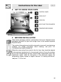
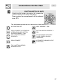
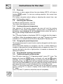
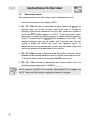
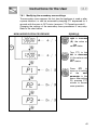
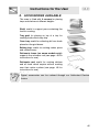
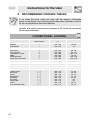
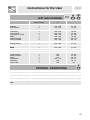
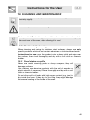
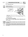
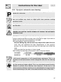
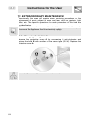
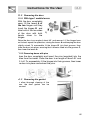
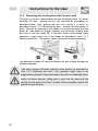
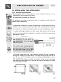
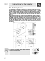
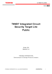
Table of Contents
1.
2.
3.
4.
5.
6.
7.
8.
9.
10.
11.
12.
PRECAUTIONS FOR USE ......................................................... 32
DISPOSAL INSTRUCTIONS - OUR ENVIRONMENT POLICY33
SAFETY PRECAUTIONS ........................................................... 34
GET TO KNOW YOUR OVEN.................................................... 35
BEFORE INSTALLATION........................................................... 35
DESCRIPTION OF FRONT PANEL CONTROLS ......................36
USING THE OVEN ..................................................................... 38
ACCESSORIES AVAILABLE...................................................... 45
RECOMMENDED COOKING TABLES ...................................... 46
CLEANING AND MAINTENANCE.............................................. 49
EXTRAORDINARY MAINTENANCE.......................................... 54
INSTALLING THE APPLIANCE.................................................. 57
INSTRUCTIONS FOR THE USER: these provide recommendations for
use, a description of the controls and the correct procedures for cleaning
and maintaining the appliance
INSTRUCTIONS FOR THE INSTALLER: these are intended for the
qualified engineer who is to install, commission and test the appliance
31
Precautions for Use
1. PRECAUTIONS FOR USE
THIS MANUAL IS AN INTEGRAL PART OF THE APPLIANCE. TAKE GOOD CARE
OF IT AND KEEP IT TO HAND THROUGHOUT THE OVEN'S LIFE CYCLE.
WE URGE YOU TO READ THIS MANUAL AND ALL THE INFORMATION IT
CONTAINS CAREFULLY BEFORE USING THE APPLIANCE. INSTALLATION
MUST BE CARRIED OUT BY QUALIFIED STAFF IN COMPLIANCE WITH THE
RELEVANT REGULATIONS. THIS APPLIANCE IS INTENDED FOR HOUSEHOLD
USE AND COMPLIES WITH THE EEC DIRECTIVES CURRENTLY IN FORCE.
THE APPLIANCE IS BUILT TO PROVIDE THE FOLLOWING FUNCTION:
COOKING AND HEATING FOODS; ALL OTHER USES ARE TO BE
CONSIDERED IMPROPER.
THE MANUFACTURER DECLINES ALL LIABILITY FOR USES OTHER THAN
THOSE STATED ABOVE.
NEVER USE THIS APPLIANCE FOR HEATING ROOMS.
NEVER LEAVE PACKAGING RESIDUES UNATTENDED IN THE HOME.
SEPARATE THE VARIOUS PACKAGING MATERIALS BY TYPE AND CONSIGN
THEM TO THE NEAREST SEPARATE DISPOSAL CENTRE.
THIS APPLIANCE IS TAGGED UNDER EUROPEAN DIRECTIVE 2002/96/EC ON
WASTE ELECTRICAL AND ELECTRONIC EQUIPMENT (WEEE).
THIS DIRECTIVE CONTAINS THE REGULATIONS GOVERNING THE
COLLECTION AND RECYCLING OF DECOMMISSIONED APPLIANCES
THROUGHOUT THE EUROPEAN UNION.
NEVER OBSTRUCT THE OPENINGS
VENTILATION AND HEAT DISPERSAL.
AND
SLITS
PROVIDED
FOR
THE NAMEPLATE WITH THE TECHNICAL DATA, SERIAL NUMBER AND MARK
IS IN A VISIBLE POSITION ON THE OVEN DOOR FRAME.
THE NAMEPLATE MUST NEVER BE REMOVED.
NEVER USE METAL SCOURING PADS OR SHARP SCRAPERS;
THEY WILL DAMAGE SURFACES.
USE ORDINARY NON-ABRASIVE PRODUCTS WITH THE AID OF
WOODEN OR PLASTIC UTENSILS IF NECESSARY. RINSE
THOROUGHLY AND DRY WITH A SOFT CLOTH OR CHAMOIS
LEATHER.
DO NOT ALLOW SPILLS OF FOODS WITH HIGH SUGAR CONTENT
(E.G. JAM) TO DRY INSIDE THE OVEN. IF THEY DRY FOR TOO
LONG, THEY MIGHT DAMAGE THE ENAMEL COATING OF THE
INSIDE OF THE OVEN.
32
Disposal instructions
2. DISPOSAL
INSTRUCTIONS
ENVIRONMENT POLICY
-
OUR
Our products are only packaged using non-pollutant, environment-friendly,
recyclable materials. We urge you to cooperate by disposing of the
packaging properly. Contact your local dealer or the competent local
organisations for the addresses of collection, recycling and disposal
facilities.
Never leave all or part of the packaging lying around. Packaging parts, and
especially plastic bags, may represent a suffocation hazard for children.
Your old appliance must also be disposed of properly.
Important: deliver the appliance to your local organisation authorised to
collect scrapped appliances. Proper disposal allows the intelligent
recovery of valuable materials.
Before scrapping your appliance it is important to remove doors and leave
shelves in position as for use, to ensure that children cannot accidentally
become trapped inside the oven during play. Also, cut the power supply
lead and remove it and the plug.
33
Safety precautions
3. SAFETY PRECAUTIONS
REFER TO THE INSTALLATION INSTRUCTIONS FOR THE SAFETY
REGULATIONS FOR ELECTRIC OR GAS APPLIANCES AND VENTILATION
FUNCTIONS.
IN YOUR INTEREST AND TO ENSURE YOUR SAFETY, BY LAW ALL ELECTRIC
APPLIANCES MUST ONLY BE INSTALLED AND SERVICED BY QUALIFIED
STAFF, IN ACCORDANCE WITH THE RELEVANT REGULATIONS.
OUR APPROVED INSTALLATION ENGINEERS GUARANTEE YOU A JOB WELL
DONE.
GAS OR ELECTRIC APPLIANCES MUST ALWAYS BE DISCONNECTED BY
SUITABLY SKILLED PEOPLE.
THE PLUG TO BE CONNECTED TO THE POWER SUPPLY LEAD AND THE
RELATIVE SOCKET MUST BE OF THE SAME TYPE AND COMPLY WITH THE
RELEVANT REGULATIONS.
THE POWER SUPPLY SOCKET MUST BE ACCESSIBLE EVEN AFTER THE
APPLIANCE HAS BEEN BUILT-IN.
NEVER DISCONNECT THE PLUG BY PULLING ON THE POWER SUPPLY
LEAD.
THE APPLIANCE MUST BE CONNECTED TO EARTH IN COMPLIANCE WITH
ELECTRICAL SYSTEM SAFETY REGULATIONS.
IMMEDIATELY AFTER INSTALLATION, CARRY OUT A QUICK TEST ON THE
APPLIANCE FOLLOWING THE INSTRUCTIONS PROVIDED LATER IN THIS
MANUAL. IF THE APPLIANCE FAILS TO OPERATE, DISCONNECT IT FROM
THE ELECTRICAL MAINS AND CONTACT YOUR NEAREST SERVICE CENTRE.
NEVER ATTEMPT TO REPAIR THE APPLIANCE.
NEVER PLACE INFLAMMABLE OBJECTS IN THE OVEN: IF IT SHOULD
ACCIDENTALLY BE SWITCHED ON, THIS MIGHT CAUSE A FIRE.
THE APPLIANCE BECOMES VERY HOT DURING USE. TAKE CARE NOT TO
TOUCH THE HEATING ELEMENTS INSIDE THE OVEN.
THE APPLIANCE IS INTENDED FOR USE BY ADULTS. KEEP CHILDREN AT A
SAFE DISTANCE AND NEVER ALLOW THEM TO PLAY WITH IT.
WHEN THE GRILL IS IN OPERATION, ACCESSIBLE PARTS MAY BECOME
VERY HOT: KEEP CHILDREN AT A SAFE DISTANCE.
AFTER EACH USE, ALWAYS CHECK THAT THE CONTROL KNOBS ARE TURNED
TO 0 (OFF).
BEFORE THE APPLIANCE IS PUT INTO OPERATION, ALL THE PROTECTIVE
FILMS APPLIED ON THE OUTSIDE MUST BE REMOVED.
The manufacturer declines all responsibility for injury or damage caused by failure to
comply with the above regulations or deriving from tampering with even just one part
of the appliance and the use of non-original spare parts.
34
Instructions for the User
4. GET TO KNOW YOUR OVEN
CONTROL PANEL
OVEN LIGHT
OVEN FAN
SHELF AND TRAY RUNNERS
TEMPERATURE SENSOR
5. BEFORE INSTALLATION
Never leave packaging residues unattended in the home. Separate waste
packaging materials by type and consign them to the nearest separate
disposal centre.
The inside of the appliance should be cleaned to remove all manufacturing
residues. For further information about cleaning, see point "10.
CLEANING AND MAINTENANCE".
When the oven and grill are used for the first time, they should be heated
to the maximum temperature for long enough to burn off any oily residues
left by the manufacturing process, which might contaminate foods with
unpleasant smells. After an interruption in the electricity supply, the
programmer display flashes at regular intervals. For setting instructions,
see point "7.3 First use".
35
Instructions for the User
6. DESCRIPTION OF FRONT PANEL CONTROLS
All the appliance's control and monitoring devices are placed together on
the front panel. The table below provides the key to the symbols used.
THERMOSTAT-TIMER KNOB
PT1
This knob allows you to set the time, select the
cooking temperature and duration and program
the cooking start and end times. From now on,
for convenience it will be referred to as PT1.
For instructions on how to use it correctly, see
point “7.3 First use” and “7.5 Programmed
cooking procedures”.
DISPLAY
DSP1
With the oven off, the 4-figure LED display shows the current time; when
the oven is in operation, it shows the temperature set and the cooking
duration set.
The display also contains the function cutout light
Secondary menu”), the timer pilot light
programmed cooking operations
,
(see point “7.6
, the symbols relating to the
and the door locked symbol
From now on, for convenience it will be referred to as DSP1.
36
.
Instructions for the User
FUNCTION-SWITCH ON KNOB
PT2
Simply turn this knob to the right or left to select the
function required, from those listed below.
From now on, for convenience it will be referred
to as PT2.
The table below provides a short description of the functions available:
NO FUNCTION SET
GRILL ELEMENT + FAN
GRILL ELEMENT IN OPERATION
ALTERNATING WITH BOTTOM
HEATING ELEMENT + FAN
BOTTOM HEATING ELEMENT +
FAN
TOP + BOTTOM HEATING
ELEMENTS
ECO AUTOMATIC CLEANING
CYCLE (ENERGY SAVING
PYROLYSIS)
GRILL ELEMENT
AUTOMATIC CLEANING CYCLE
(PYROLYSIS)
TOP + BOTTOM HEATING
ELEMENTS+FAN
37
Instructions for the User
7. USING THE OVEN
7.1
Precautions and General Advice
All cooking operations must be carried out with the door closed
When the oven and grill are used for the first time, they should be heated
to the maximum temperature for long enough to burn off any oily residues
left by the manufacturing process, which might contaminate foods with
unpleasant smells.
During cooking, do not cover the bottom of the oven with aluminium
or tin foil, and do not place pans or trays on it; this may damage the
enamel coating. If you wish to use greaseproof paper, position it so
that it does not interfere with the hot air circulation inside the oven.
Oven accessories which may come into contact with foods are made from
materials compliant with directive 89/109/EEC of 21/12/88 and relevant
national regulations.
To avoid unpleasant contact with any steam inside
the oven, open the door in two stages: hold it halfopen (about 5 cm) for 4-5 seconds, then open it
completely. If you have to carry out any procedures
on foods, leave the door open for as short a time as
possible to prevent a drop in the oven temperature
which will impair the cooking results.
To prevent excessive amounts of condensation from forming on the
internal glass, food should not be left inside the oven for too long after
cooking.
7.2
Operating modes
This appliance is programmed to provide 3 operating settings:
OFF setting: obtained with knob PT2 turned to the “0” symbol and current
time shown on the display.
ON setting: obtained with selector knob PT2 turned to any function and
temperature set or PYro, if in pyrolysis, shown on the display.
Standby setting: obtained with selector knob PT2 turned to any function
and a timed cooking operation set and current time shown on the display.
38
Instructions for the User
7.3
First use
At first use, or after a power failure, the oven display (DSP1), will show a
flashing
symbol. To start any cooking operation, the current time
must be set.
(For further information about setting or adjusting the current time, see
point "7.6 Secondary menu").
7.4
Selecting the function
To select a cooking function, turn PT2.
Then select the temperature required.
7.4.1 Cooking with preset temperature
After selection of the function required, the oven will start the cooking
procedure at the preset temperature. Cooking itself is preceded by a
preheating stage (common to all functions) which allows the oven to
heat to the cooking temperature more quickly.
The
symbol flashes on the display (DSP1) to indicate that this stage is
in progress. When the preheating stage is over, the
symbol will remain
constantly on to indicate that the food can be placed inside the oven.
7.4.2 Changing the preset temperature
The temperature preset for each function can be changed to suit the user's
requirements.
At any time while cooking is in progress, turn PT1 in either direction to
increase or decrease the cooking temperature by 5 degrees at a time. PT1
can also be held in the left or right position to increase or decrease the
setting more quickly.
7.5
Programmed cooking procedures
7.5.1 Timed cooking with minute minder
From ON status (see point “7.2 Operating modes”), press PT1 once. The
display will show the
figures (constantly on) and the
symbol
(flashing). Turn PT1 to set the minutes of cooking (from 00:01 to 23:59). A
few seconds later, the
symbol will stop flashing, and the countdown will
start from that moment. Now you can also select the cooking function required
and wait for the buzzer to sound, indicating that the cooking time is over.
Press PT1 once to stop the buzzer. You can now set an additional cooking
time by turning PT1, or return to display of the current time by pressing
PT1 twice.
Turn PT2 to the "0" symbol to switch the oven off completely.
The minute minder also works with no function set.
39
Instructions for the User
Warning: the minute minder does not stop the cooking process. It only
warns the user that the preset number of minutes have passed.
To switch the oven off completely, turn PT2 to the "0" symbol.
Modifying the data set
Once the countdown has started, its duration can be changed while
cooking is in progress.
When the
symbol is steady, press PT1 once. The
symbol starts
flashing and PT1 can be turned to change the set duration. A few seconds
after the last change, the
symbol will stop flashing, and the countdown
will restart from the new value.
To change the preset temperature, wait for the
symbol to become
steady and turn PT1 to the right or left to increase or decrease the cooking
temperature.
7.5.2 Semiautomatic cooking
Semiautomatic cooking is the function which allows a cooking operation to
be started and then ended after a specific length of time set by the user.
Select a cooking function (see point “7.4 Selecting the function”) and press
PT1 twice. The display will show the
figures and the
symbol
(flashing).
Turn PT1 to the right or left to set the minutes of cooking (from 00:01 to
23:59). A few seconds after the required duration is set, the
symbol will
stop flashing, and semiautomatic cooking will start from that moment. At
the end, the word STOP will appear on DSP1, cooking will stop and a
buzzer will sound; press PT1 once to deactivate it.
If you wish to continue cooking beyond the set time, press PT1 again. The
oven will restart normal operation with the cooking settings selected
previously.
Turn PT2 to the "0" symbol to switch the oven off completely.
Modifying the data set
Once semiautomatic cooking has started, its duration can be changed.
When the
symbol is steady, press PT1 once. The
symbol starts
flashing and PT1 can be turned to change the set duration. A few seconds
after the last change, the
symbol will stop flashing, and semiautomatic
cooking will restart from the new value.
To change the preset temperature, wait for the
symbol to become
steady and turn PT1 to the right or left to increase or decrease the cooking
temperature.
40
Instructions for the User
7.5.3 Automatic cooking
Automatic cooking is the function which allows a cooking operation to be
started at a set time and then ended after a specific length of time set by
the user.
Select a cooking function, set the cooking temperature required or leave
the preset temperature (see point “7.4 Selecting the function”) and press
PT1 twice. The display will show the
figures and the
symbol
(flashing).
Turn PT1 to the right or left to set the minutes of cooking (from 00:01 to
23:59).
For reasons of safety, when setting automatic cooking the user must first
program a cooking duration and then set the cooking start time. It is not
possible to set the cooking start time only, without setting the cooking
duration.
After setting the duration, press PT1 once.
The
symbol and the current time will appear on the display.
Turning PT1 to the right increases the time, allowing the cooking start
time required to be set.
A few seconds after the required duration is set, the
and
symbols
will stop flashing and will become solid, and the oven will start to wait for
the starting time set. At the end, the word STOP will appear on DSP1,
cooking will stop and a buzzer will sound; press PT1 once to deactivate it.
If you wish to continue cooking beyond the set time, press PT1 again. The
oven will restart normal operation with the cooking settings selected
previously.
Turn PT2 to 0 to switch off the oven.
Modifying the data set
Once automatic cooking has started, its duration can be changed.
When the
and
symbols are steady and cooking is in progress, or
the oven is in standby status waiting for cooking to start, press PT1 once.
The
symbol starts flashing and PT1 can be turned to change the set
duration.
Press PT1 again; the
symbol goes out, the
symbol will start to
flash, and the cooking start time will be displayed on DSP1. The cooking
start time can be increased or decreased by turning PT1.
A few seconds after the last change, the
e
symbols will appear (in
steady mode) on DSP1 and automatic cooking will restart with the new
settings.
41
Instructions for the User
7.6
Secondary menu
This appliance also has a "secondary menu" allowing the user to:
1
Set the time shown on the display (DSP1).
2
(P1: OF / ON) Activate or deactivate the child safety lock (
); this
function locks out all the functions and knobs after 2 minutes of
operation without any command from the user (when this system is
active, the
symbol appears on DPS1). To exit the lockout status
temporarily to modify a cooking program or select a different function,
keep PT1 pressed until the
symbol disappears from DSP1. The
required changes can now be made, and 2 minutes after the last
setting is made the lockout will come into operation again. To
deactivate the lockout permanently, access the secondary menu and
switch the function off as described in this section.
3
(P2: OF / ON) Activate or deactivate the Show Room function, which
disables all the heating elements so that only the control panel works.
To allow the oven to be used normally, P2:OFF must be set.
4
(P3: OF / ON) Activate or deactivate the function which limits the
maximum power absorption to 2300 W.
When the child safety lock is activated (P1:ON), if a knob is turned
“bLOC” appears on DSP1 for 2 seconds. Operating PT2 also triggers the
“bLOC” alarm until the function originally selected is restored.
42
Instructions for the User
7.6.1 Modifying the secondary menu settings
The secondary menu appears the first time the appliance is used or after
a power blackout, or can be accessed by keeping PT1 depressed for 3
seconds with the oven in OFF status (see point “7.2 Operating modes”).
Changing the settings of the secondary menu parameters is very easy.
Refer to the chart below:
MENU MODIFICATION PROCEDURE
SYMBOLS
Turn PT1 to the
right to increase
+
( ) the value or
set ON status.
Turn PT1 to the
left to decrease
-
( ) the value or set
Off status.
Press
PT1
to
move on to setting
next
of
the
parameter in the
menu. After setting
P3, pressing PT1
returns to normal
oven operation.
43
Instructions for the User
7.7
Cooling fan system
The appliance is equipped with a cooling
system which comes into operation as
soon as a cooking function or a cleaning
cycle (Pyrolysis) starts.
Operation of the fans generates a normal
air flow which comes out above and
underneath the door and may continue
for a short time even after the oven is
switched off.
7.8
Inside light
The oven light comes on:
• when the oven door is opened in OFF status (point “7.2 Operating
modes”) or
•
44
when the function knob is turned to any function, except
and
.
Instructions for the User
8. ACCESSORIES AVAILABLE
The oven is fitted with 4 runners for placing
trays and shelves at different heights.
Shelf: useful to support pans containing the
food for cooking.
Tray grid: for placing on top of a tray for
cooking foods which may drip.
Oven tray: useful for collecting fat from foods
placed on the grid above.
Baking tray: useful for cooking cakes, pizza
and confectionery.
Rotisserie frame (on some models only):
supports the rotisserie rod (see page 48 for
instructions for use).
Rotisserie rod: useful for cooking chicken
and all foods which require uniform cooking
over their entire surface (see page 48 for
instructions for use).
Optional accessories
Original accessories can be ordered through our Authorised Service
Centres.
45
Instructions for the User
9. RECOMMENDED COOKING TABLES
The oven must be preheated before all cooking operations.
Do not place the foods inside the oven until the degrees Centigrade
symbol on the display stops flashing and the beep has sounded to confirm
that the set temperature has been reached.
Cooking times, for meat in particular, vary depending on the food's
thickness and quality and personal preference. All times are calculated
with the oven preheated.
CONVENTIONAL COOKING
RUNNER POSITION FROM
THE BOTTOM
TEMPERATURE
°C.
TIME IN MINUTES
PASTA
LASAGNE
PASTA BAKES
1
1
220 - 230
220 - 230
50 - 60
40
MEAT
ROAST VEAL
LOIN OF PORK
SHOULDER OF PORK
RABBIT
TURKEY BREAST
ROAST NECK OF PORK
2
2
2
2
2
2
190 - 200
190 - 200
190 - 200
190 - 200
190 - 200
190 - 200
80 - 90
80 - 90
100 - 110
70 - 80
160 - 180
190 - 210
FISH
1-2
160 - 170
Depending on size
PIZZA
1-2
250
20 - 25
BREAD
1-2
200 - 210
40
2
190 - 200
20 - 25
1-2
1-2
1-2
1-2
1-2
1-2
1-2
1-2
1-2
160 - 170
160 - 170
160 - 170
160 - 180
160 - 170
160 - 170
160 - 170
160 - 170
160 - 170
55 - 60
30 - 40
20 - 25
25 - 30
30 - 35
60
60
40 - 45
40 - 45
MUFFINS
CONFECTIONERY
SPONGE CAKE
FRUIT TART
PASTRY
CROISSANTS
JAM TARTS
RICE CAKE
ANGEL CAKE
ECLAIR
LIGHT SPONGE CAKE
46
Instructions for the User
HOT AIR COOKING
RUNNER POSITION FROM
THE BOTTOM
TEMPERATURE
°C.
TIME IN MINUTES
PASTA
LASAGNE
PASTA BAKES
2
2
210 - 230
210 - 230
45 - 50
25 - 30
MEAT
ROAST VEAL
LOIN OF PORK
SHOULDER OF PORK
RABBIT
TURKEY BREAST
ROAST CHICKEN
2
2
2
2
2
2
180 - 190
180 - 190
180 - 190
180 - 190
180 - 190
180 - 190
70 - 80
70 - 80
90 - 100
70 - 80
110 - 120
60 - 70
FISH
SALMON TROUT
PIZZA
BREAD
MUFFINS
CONFECTIONERY
SPONGE CAKE
LARGE JAM TART
PASTRY
CROISSANTS
JAM TARTS
ANGEL CAKE
2
150 - 160
35 - 40
1-2
250
15 - 20
1
190 - 200
25 - 30
1-2
180 - 190
15 - 20
2
2
2
2
2
2
160
160
170
160 - 170
160
160
50 - 60
25 - 30
20 - 25
20 - 25
20 - 25
60
PROVING - DEFROSTING
TEMPERATURE °C
DEFROSTING FOODS
NATURAL YEAST DOUGHS
30
35 - 40
For successful proving, a container of water should be placed in the bottom of the
oven.
47
Instructions for the User
GRILLING
PORK CUTLET
PORK FILLET
FILLET STEAK
SLICED LIVER
VEAL ESCALOPES
HALF CHICKEN
SAUSAGE
MEATBALLS
FISH FILLET
TOASTED SANDWICHES
RUNNER POSITION FROM
THE BOTTOM
1ST SIDE
TIME IN MINUTES
2ND SIDE
4
3
3
4
4
3
3
3
3
3
7-9
9 - 11
9 - 11
2-3
7-9
9 - 14
7-9
7-9
5-6
2-4
5-7
5-9
9 - 11
2-3
5-7
9 - 11
5-6
5-6
3-4
2-3
ROTISSERIE COOKING
Prepare the rotisserie rod with the food, tightening the screws A of the prongs. Fit the
frame B onto the second runners from the bottom. Remove the handle D and position
the rotisserie rod so that the pulley E is still in the guides on the frame B. Push the
frame B fully in until the tip of the rotisserie rod enters the hole C on the rear wall of
the oven. Place a basin F on the bottom bottom shelf and pour a little water into it to
prevent smoke from forming.
48
Instructions for the User
10. CLEANING AND MAINTENANCE
Before carrying out any operations, disconnect the appliance from the
electricity supply.
Never use a jet of steam for cleaning the inside of the oven.
10.1 Cleaning stainless steel
To keep stainless steel in good condition, it must be cleaned regularly,
after each use of the oven, after allowing it to cool.
10.2 Routine daily cleaning
When cleaning and caring for stainless steel surfaces, always use only
specific products which do not contain abrasives or chlorine-based acids.
Instructions for use: pour the product onto a damp cloth and wipe over
the surface, then rinse thoroughly and dry with a soft cloth or chamois
leather.
10.3 Food stains or spills
Never use metal scouring pads or sharp scrapers; they will
damage surfaces.
Use ordinary non-abrasive products with the aid of wooden or
plastic utensils if necessary. Rinse thoroughly and dry with a soft
cloth or chamois leather.
Do not allow spills of foods with high sugar content (e.g. jam) to
dry inside the oven. If they dry for too long, they might damage
the enamel coating of the inside of the oven.
49
Instructions for the User
10.4 Cleaning the oven
To keep the oven in good condition, it must be cleaned regularly, after
allowing it to cool down.
Remove all removable parts.
•
•
Clean the oven shelves with hot water and non-abrasive detergents,
rinse and dry.
For easier cleaning, the door can be removed (see point “11.2
Removing the door”)
10.5 Cleaning the door glazing
The glass in the door should always be kept thoroughly clean. Use
absorbent kitchen roll; remove stubborn dirt with a damp sponge and
ordinary detergent.
Do not use abrasive or corrosive cleaners for cleaning the door glazing
(e.g. powder products, oven-cleaner sprays, stain removers and metal
scouring pads).
Do not use rough or abrasive materials or sharp metal scrapers to clean
the oven's glass doors since they may scratch the surface and cause the
glass to shatter.
50
Instructions for the User
10.6 Pyrolysis: automatic oven cleaning
Pyrolysis is an automatic high-temperature cleaning procedure which
causes dirt to dissolve.
Before starting the automatic cleaning cycle, make sure that the oven
does not contain any foods or large spills from previous cooking
operations inside.
During the pyrolysis cycle adoor interlock device makes it impossible to
open the door.
IF THE OVEN IS INSTALLED UNDERNEATH A HOB, MAKE SURE THAT THE
BURNERS OR ELECTRIC PLATES REMAIN OFF DURING THE AUTOMATIC
CLEANING CYCLE.
10.6.1 Before starting the automatic cleaning cycle
Pyrolysis may be carried out at any time of the day or night (if you wish to
benefit from the lower cost of electricity overnight).
Before proceeding, check the following:
• only the baking tray and the oven tray may be left inside the oven
since they will withstand the high temperatures of the pyrolysis
process; all the other accessories must be removed from inside the
oven.
• make sure that the oven door is firmly closed.
When setting the cleaning cycle duration, refer to the chart below:
CLEANING
DURATION
LIGHT DIRT
MEDIUM DIRT
HEAVY DIRT
90 MIN.
135 MIN.
180 MIN.
During the first automatic cleaning cycle unpleasant smells may occur due
to the normal evaporation of oily manufacturing substances. This is an
absolutely normal phenomenon which disappears after the first cleaning
cycle.
During the automatic cleaning cycle the fans make more noise because
they are running at higher speed. This is an absolutely normal function,
intended to provide more effective heat dispersal. At the end of the
pyrolysis process the fans continue to run automatically for long enough to
prevent overheating of the sides of the cabinet and the front of the oven.
51
Instructions for the User
10.6.2 How the automatic cleaning cycle works
The table below shows an example of operation of the automatic cleaning
cycle.
About 2 minutes after the cleaning cycle starts an interlock device which
prevents opening of the door is tripped.
At the end of the cleaning cycle the thermostat light goes out.
The door interlock is only released later, when the temperature inside the
oven drops back below 300°C.
52
ON
-
ON
300 °C
OFF
500 °C
OFF
300 °C
Instructions for the User
10.6.3 Setting the cleaning cycle
Use PT2 to select one of the two pyrolysis functions (
and
) with the
oven in OFF status (see point 7.4, Function Selection).
To start the cleaning (Pyrolysis) cycle, press knob PT1 once to set its
duration (
).
Turn knob PT1 to the right or left to increase or decrease the cycle
duration between a minimum of 1h 30m and a maximum of 3h 00m
(except for the
function where the cycle duration is fixed at 1h 30m).
The message PYro will appear on DSP1 to indicate that the oven is
function, DSP1 shows Peco).
performing the cleaning cycle (for the
One minute after the cleaning (Pyrolysis) cycle starts an interlock device
which prevents opening of the door will be tripped.
The
symbol illuminates on DSP1 to indicate that this interlock device
has been activated.
To select a cleaning cycle with delayed start, after setting the duration
press PT1 once. The
symbol and the current time will appear on the
display.
Turning PT1 to the right increases the time, allowing the cleaning start
time required to be set.
A few seconds after the required duration is set, the
and
symbols
will stop flashing, and the oven will start to wait for the starting time set.
It is not possible to select any functions once the door interlock has been
activated. Wait for the
symbol to go out.
53
Instructions for the User
11. EXTRAORDINARY MAINTENANCE
Occasionally, the oven will require minor servicing procedures or the
replacement of parts subject to wear and tear, such as gaskets, light
bulbs, etc. The specific operations for each procedure of this kind are
provided below.
Before carrying out any operation involving access to live parts,
disconnect the appliance from the electricity supply.
11.1 Changing the light bulb
Remove the protective cover A by unscrewing it anti-clockwise and
replace the bulb B with another of the same type (25 W). Replace the
protective cover A.
Use only light bulbs approved for ovens (T 500°C).
54
Instructions for the User
11.2 Removing the door
11.2.1 With type 1 mobile levers
With the door completely
open, lift the levers A of
the two hinges until they
touch the hinges B and
take hold of the two sides
of the door with both 1)
hands close to the
hinges.
Raise the door to an angle of about 45° and remove it. If the hinges have
not locked, repeat the operation, raising the levers A and keeping the door
slightly raised. To reassemble, fit the hinges B into their grooves, then
lower the door into place, ensuring that it remains fitted into the grooves C,
then lower the levers A.
11.2.2 Removing doors with pins
Open the door completely and insert the pins (supplied) into the
holes from the inside. Close the door to an angle of about 45° and
lift it off. To reassemble, fit the hinges into their grooves, then lower
the door into place and extract the pins.
11.3 Removing the gasket
To allow thorough cleaning of the
oven, the door gasket can be
removed.
55
Instructions for the User
11.4 Removing the inside glass with the door cold
The glass in the door should always be kept thoroughly clean. For easier
cleaning, the door glazing can be fully removed by proceeding as
described below. After opening the door and locking it in place as
described in point “11.2 Removing the door”, remove the three panes of
glass. They are all removed in two stages: first extract the pane from the
guide “A” (see detail) by sliding it towards you and lifting it slightly, then
also free it from the guide "B". If the door should close during these
operations, simply relock one of the hinges as described in point "11.2
Removing the door". The panes of glass can now be washed separately.
Use absorbent kitchen roll; remove stubborn dirt with a damp sponge and
ordinary detergent.
Caution: before removing the panes of glass, make sure that at least one
of the door's hinges has been locked in open position as described in
points “11.2 Removing the door”. This operation might have to be
repeated during the glass removal process if the door is accidentally freed.
Caution: replace the panes of glass in the same order and in the same
position as before removal, taking care to push the last pane with the
marking into the guide A to lock it in place. When complete, release the
hinges and close the door.
56
Instructions for the Installer
12. INSTALLING THE APPLIANCE
12.1 Electrical connection
The nameplate with the technical data, serial number and mark is in a
visible position on the oven door frame.
The nameplate must never be removed.
The appliance must be connected to earth in compliance with electrical
system safety regulations.
If a permanent connection is used, the appliance's power supply line must
be fitted with an omnipolar breaking device with contact gap of at least 3
mm, located in an easily accessible position close to the appliance itself.
If a socket and plug connection is used, check that they are of the same
type. Do not use reducers, adapters or junctions since they may cause
overheating or burns.
Operation at 220-240 V~: use a
type H05RR-F (3 x 1.5 mm2) or
type H05V2V2-F (3 x 1.5 mm2)
three-wire cable.
The earth wire (yellow-green)
must be at least 20 mm longer
than the other wires at the end
for connection to the appliance.
If the power supply lead has to be replaced, remove the rear casing by
undoing the screws as shown below. The power lead gauge must be at
least 1.5 mm2 (3 X 1.5 cable) and it must withstand temperatures up to
90°C (H05V2V2-F). Make sure that the cables follow the best possible
route and use band clamps to fix them at the side of the cabinet, to avoid
any contact with the oven.
57
Instructions for the Installer
12.2 Positioning the oven
The appliance is designed for building-in to cabinets made from any heatresistant material. Comply with the dimensions shown in figures 1, 2 and
3. When installing under worktops, comply with the dimensions shown in
figure 1-3. When installing under worktops incorporating combined hobs,
a gap of at least 110 mm must be left from any side wall, as shown in
figure 1.
When installing in tall units, comply with the dimensions shown in figure 12, bearing in mind that the top/rear of the unit must have an opening 80-90
mm deep. Screw the 2 screws A into the inside of the frame (fig. 1). For
installation under counter-top hobs, make sure that the rear/bottom of the
unit has an opening similar to that shown in figure 1 (ref. B). See the
instructions supplied with the hob for the relative positioning and fixing
procedures.
Never use the door for leverage when inserting
the oven in the cabinet. Never apply excessive
pressure to the open door.
58