1
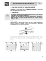
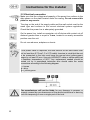
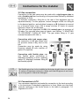
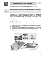
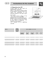
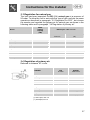
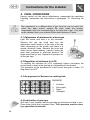
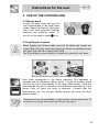
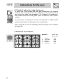
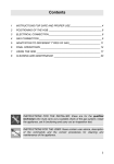
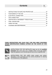
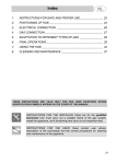
Contents
1.
INSTRUCTIONS FOR SAFE AND PROPER USE _______________19
2.
INSTALLATION OF THE APPLIANCE ________________________21
3.
ADAPTING TO DIFFERENT TYPES OF GAS __________________25
4.
FINAL OPERATIONS______________________________________28
5.
USE OF THE COOKING HOB _______________________________29
6.
CLEANING AND MAINTENANCE ____________________________31
THESE INSTRUCTIONS ARE VALID ONLY FOR END USER COUNTRIES WHOSE
IDENTIFICATION SYMBOLS APPEAR ON THE COVER OF THIS MANUAL.
INSTRUCTIONS FOR THE INSTALLER: these are for the qualified
technician who must carry out a suitable check of the gas system,
install the appliance, set it functioning and carry out an inspection test.
INSTRUCTIONS FOR THE USER: these contain user advice,
description of the commands and the correct procedures for cleaning
and maintenance of the appliance.
18
Introduction
1. INSTRUCTIONS FOR SAFE AND PROPER USE
THIS MANUAL IS AN INTEGRAL PART OF THE APPLIANCE AND
THEREFORE MUST BE KEPT IN ITS ENTIRETY AND IN AN ACCESSIBLE
PLACE FOR THE WHOLE WORKING LIFE OF THE COOKING HOB. WE
ADVISE READING THIS MANUAL AND ALL THE INSTRUCTIONS
THEREIN BEFORE USING THE COOKING HOB. ALSO KEEP THE SERIES
OF NOZZLES SUPPLIED. INSTALLATION MUST BE CARRIED OUT BY
QUALIFIED PERSONNEL IN ACCORDANCE WITH THE REGULATIONS IN
FORCE. THIS APPLIANCE IS INTENDED FOR DOMESTIC USES AND
CONFORMS TO CURRENT REGULATIONS IN FORCE. THE APPLIANCE
HAS BEEN BUILT TO CARRY OUT THE FOLLOWING FUNCTIONS:
COOKING AND HEATING-UP OF FOOD. ALL OTHER USES ARE
CONSIDERED IMPROPER.
THE MANUFACTURER DECLINES ALL RESPONSIBILITY FOR
IMPROPER USE.
DO NOT LEAVE THE PACKING IN THE HOME ENVIRONMENT.
SEPARATE THE VARIOUS WASTE MATERIALS AND TAKE THEM TO
THE NEAREST SPECIAL GARBAGE COLLECTION CENTRE.
IT IS OBLIGATORY FOR THE ELECTRICAL SYSTEM TO BE GROUNDED
ACCORDING TO THE METHODS REQUIRED BY SAFETY RULES.
THE PLUG TO BE CONNECTED TO THE POWER CABLE AND THE
SOCKET MUST BE THE SAME TYPE AND MUST CONFORM TO
CURRENT REGULATIONS.
NEVER UNPLUG BY PULLING ON THE CABLE.
IMMEDIATELY AFTER INSTALLATION CARRY OUT A BRIEF INSPECTION
TEST OF THE COOKING HOB, FOLLOWING THE INSTRUCTIONS
BELOW. SHOULD THE APPLIANCE NOT FUNCTION, DISCONNECT IT
FROM THE SUPPLY AND CALL THE NEAREST TECHNICAL ASSISTANCE
CENTRE.
NEVER ATTEMPT TO REPAIR THE APPLIANCE.
ALWAYS CHECK THAT THE CONTROL KNOBS ARE IN THE POSITION
OR 0 (OFF) WHEN YOU FINISH USING THE HOB.
THE IDENTIFICATION PLATE, WITH TECHNICAL DATA, SERIAL NUMBER
AND MARKING IS CLEARLY VISIBLE UNDER THE CASING.
THE PLATE ON THE CASING MUST NOT BE REMOVED.
19
Introduction
DO NOT PUT PANS WITHOUT PERFECTLY SMOOTH AND FLAT
BOTTOMS ON THE COOKING HOB GRIDS.
DO NOT USE RECIPIENTS OR GRIDDLE PLATES THAT EXTEND
BEYOND THE EXTERNAL PERIMETER OF THE HOB.
THE HOB IS TO BE USED BY ADULTS ONLY. DO NOT LET
UNSUPERVISED CHILDREN PLAY WITH THE HOB.
REPLACED APPLIANCES MUST BE TAKEN TO A SPECIAL GARBAGE
COLLECTION CENTRE.
The manufacturer declines all responsibility for damage to
persons or things caused by non-observance of the above
prescriptions or by interference with any part of the appliance or by
the use of non-original spares.
20
Instructions for the installer
2. INSTALLATION OF THE APPLIANCE
Installation must be carried out by a qualified technician in compliance
with applicable regulations in force.
2.1 Positioning
The following operation requires building and/or carpentry work so must
be carried out by a competent tradesman.
Installation can be carried out on various materials such as masonry,
metal, solid wood or plastic laminated wood as long as they are heat
resistant (T 90°C).
2.1.1 Fixing
Insert screws A of the brackets provided into slots B under the appliance.
Slide the brackets into slots B. Position the appliance on to the support
frame and secure it by means of screws C.
To connect the appliance to the mains, holes have to be made in the
cabinet which vary from model to model. The dimensions of these
openings are shown by the areas marked in dotted lines in the diagrams
below.
21
Instructions for the installer
2.2 Electrical connection
Make sure that the voltage and capacity of the power line conform to the
data shown on the plate located under the casing. Do not remove this
plate for any reason.
The plug on the end of the supply cable and the wall socket must be the
same type and conform to the current electrical system regulations.
Check that the power line is adequately grounded.
On the power line, install an omnipolar cut-off device with contact cut-off
distance greater than or equal to 3 mm, located in an easily accessible
position near the unit.
Do not use reducers, adapters or shunts.
If the power cable is replaced, the wire section on the new cable must
2
not be less than 0.75 mm (3 x 0.75 cable), keeping in mind that the end
to be connected to the hob must have the ground wire (yellow-green)
longer by at least 20 mm. Use only H05V2V2-F cable or similar which has
a maximum temperature of 90°C. Any replacement needed should be
carried out by a specialised technician who should make the mains
connections according to the following diagram.
L = brown
N = blue
= yellow-green
The manufacturer will not be liable for any damage to persons or
property caused by non-observance of the above instructions or deriving
from the tampering of even a single part of the hob.
22
Instructions for the installer
2.3 Ventilation of rooms
The hob may be installed only in rooms with permanent ventilation, as
required by standards regulations in force. The room in which the hob is
installed must have sufficient air flow to satisfy the requirements of
normal gas combustion and of necessary air exchange in the room. The
air intakes, protected by screens, must be appropriately sized
(regulations in force) and placed so as not to be blocked in any way.
The room where the oven is installed should be suitably ventilated to
avoid overheating or excess humidity produced by cooking, and in the
case of lengthy use a window should be opened or the speed of any
ventilators should be increased.
2.4 Discharge of combustion products
Discharge of combustion products must be guaranteed by means of
hoods connected to a natural draught flue with certain efficiency, or by
means of forced aspiration. An efficient aspiration system requires
careful planning by a specialist capable of installing it, respecting the
positions and distances prescribed by standards. After installation, the
installer must issue a certificate of conformity.
23
Instructions for the installer
2.5 Gas connection
Connection to the gas mains may be made with a rigid copper pipe or
with a flexible pipe and conforming to the provisions defined by standard
regulations in force.
To facilitate connection, fitting A on the rear of the appliance may be
adjusted laterally. For this purpose, loosen hexagon nut B, turn fitting A
to the desired position, and retighten hexagon nut B (tightness is ensured
by a biconical brass ring). Use a soapy solution to check for proper
tightness. Never use a free flame.
The hob has been inspected for G20 (2H) natural gas at a pressure of
20 mbar. For use with other types of gases, see Section “3. ADAPTING
TO DIFFERENT TYPES OF GAS”. The gas intake fitting is ½” gas
external threaded (ISO 228-1).
Connection with rigid copper pipe:
the connection to the gas mains must
not provoke stress of any kind on the
hob.
Connection may be made by using
biconical adapter D with insertion of
gasket C (supplied).
Connection with flexible pipe: use
only flexible pipes conforming to
standard regulations in force, inserting
gasket C (supplied) between fitting A
and flexible pipe E.
The flexible pipe has to be installed so that pipe length does not exceed
1.5 meters of maximum extension. Make sure that the pipes do not touch
any moving parts or become damaged.
2.6 Connection to LPG
Use a pressure regulator and make the connection to the tank according
to the provisions of standards regulations in force. Make sure that feed
pressure conforms to the levels shown in the table in paragraph “3.2
Regulation for LPG”.
24
Instructions for the installer
3. ADAPTING TO DIFFERENT TYPES OF GAS
Before any intervention, disconnect the power supply of the device.
The cooking hob is inspection-tested for use with G20 (2H) natural gas
at a pressure of 20 mbars. If used with other types of gas, you have to
replace the nozzles and regulate the primary air to the burners. Then
regulate the minimum flame on the gas taps. For nozzle replacement and
burner adjustment you must raise the cooking hob as described in the
following paragraph.
3.1 Removing the top
1.
2.
3.
4.
5.
6.
Slide out the grids, and remove all burner caps, flame cap crowns
and burners.
Remove the screws and nuts A which hold burner supports in place.
Remove plates B.
Lift up top C with the aid of a screwdriver and remove it from its seat.
Replace the burner nozzles according to the specifications in the
reference gas table.
Adjust primary air as described in paragraph “3.2 Regulation for
LPG”.
25
Instructions for the installer
3.2 Regulation for LPG
Loosen screw A and push air
regulator B to the bottom.
With a 7 mm wrench, remove nozzle
C and replace it with the proper one
(follow the instructions on the
reference tables for the type of gas
to be used).
The torque wrench setting of the
nozzle must not exceed 3 Nm.
Regulate the air by sliding regulator
B until reaching distance “X” shown
in the table in paragraph “3.4
Regulation of primary air”.
Lock regulator B by tightening
screw A.
Burner
Rated
heating
capacity
(kW)
LPG – G30/G31 28/37 mbar
Nozzle
diameter
1/100 mm
By-pass
mm
1/100
Reduced
flowrate
(W)
Flowrate
g/h G30
Flowrate
g/h G31
Top with front controls:
Auxiliary
Semi rapid
Rapid
Ultrarapid
1.05
1.65
2.55
3.25
48
62
75
85
33
33
50
68
420
420
900
1500
76
120
185
236
75
118
182
232
Top with side controls:
Auxiliary
Semi rapid
Rapid
Ultrarapid
1.05
1.65
2.55
3.25
48
62
75
85
33
33
45
65
450
450
800
1500
76
120
185
236
75
118
182
232
26
Instructions for the installer
3.3 Regulation for natural gas
The hob has been inspected for G20 (2H) natural gas at a pressure of
20 mbar. To allow the unit to work with this type of gas, perform the same
operations described in paragraph “3.2 Regulation for LPG”, but choose
the nozzles and regulate the primary air for natural gas, as shown in the
following table and in paragraph “3.4 Regulation of primary air”.
Rated
heating
capacity
(kW)
Burner
Natural gas – G20 20 mbar
Nozzle diameter
1/100 mm
Reduced flowrate
(W)
Top with front controls:
Auxiliary
1.05
73
380
Semi rapid
Rapid
Ultrarapid
1.65
2.55
3.25
92
115
130
420
650
1400
Top with side controls:
Auxiliary
Semi rapid
1.05
1.65
73
92
380
450
Rapid
Ultrarapid
2.55
3.25
115
130
650
1400
3.4 Regulation of primary air
Referred to distance “X” in mm.
BURNER
G20
20 mbar
G30/G31
28/37 mbar
Top with front controls:
Auxiliary
2.5
2.5
Semi rapid
Rapid
Ultrarapid
1.5
2.5
1.5
2
2
2.5
3
2
3
1.7 (*)
3
1.7
2.5
3 (**)
Top with side controls:
Auxiliary
Semi rapid
Rapid
Ultrarapid
(*) Semi rapid, rear: 2.5
(**) Ultrarapid, front: 4
27
Instructions for the installer
4. FINAL OPERATIONS
Having carried out the above adjustments, reassemble the appliance
following, backwards, the instructions in paragraph “3.1 Removing the
top”.
After adjustment to a different kind of gas from the one for which the
cooker has been tested, replace the plate inside the heating
compartment with one corresponding to the new kind of gas. This plate
can be obtained from your nearest Authorised Assistance Centre.
4.1 Adjustment of minimum for natural gas
Light the burner and take it to the minimum.
Remove the gas tap knob and turn the
adjustment screw inside or at the side of the tap
shaft (depending on the model) until there is a
regular minimum flame. Replace the knob and
check burner flame stability: (rapidly turning the
knob from maximum to minimum position, the
flame should not go out). Repeat the operation on
all the gas taps.
4.2 Regulation of minimum for LPG
To regulate the minimum for LPG, completely tighten (clockwise) the
screw inside or next to the gas tap pin (depending on the model).
The diameters of the by-passes for each burner are given in table “3.2
Regulation for LPG”.
4.3 Arrangement of burners on cooking hob
BURNERS
1
2
3
4
Auxiliary
Semi rapid
Rapid
Ultrarapid
4.4 Lubrication of gas taps
With time it may happen that the gas taps get blocked and hard to turn.
Clean them inside and re-grease them. This operation must be done
by a specialised technician.
28
Instructions for the user
5. USE OF THE COOKING HOB
5.1 Burner knob
To light the flame, press and turn the
knob anticlockwise to the large flame
symbol. Adjust the flame by turning the
knob to the area comprised between
maximum and minimum marks. To
turn off, set the knob to either
or 0.
5.2 Lighting the burners
Before lighting the burners make sure that the flame cap crowns are
properly fitted into their seats and equipped with the corresponding caps,
and check that niche A is aligned with pin B.
Grid C (available in some models) is intended for use with “wok” pans.
Each knob corresponds to the burner indicated. The appliance is
equipped with an electronic lighting device. To light the burners, press
and turn the knob anticlockwise to the large flame symbol. Keep the
knob pressed for about 2 seconds to let the thermocouple heat up. If the
burner turns off when the knob is released, it means that the
thermocouple isn’t hot enough. Repeat ignition and keep the knob
pressed longer.
If the burners turn off accidentally, a safety device will trip after about 20
seconds to cut off gas flow (even with the gas tap open).
29
Instructions for the user
5.3 Practical advice for using the burners
For better use of the burners and lower gas consumption, use covered
containers that are proportional in size to the burner to prevent the flame
from licking the sides (see paragraph “5.4 Diameter of containers”).
When water reaches the boiling point, lower the flame so that it doesn’t
overflow.
To avoid burns or damage to the hob, all recipients or griddle plates
must be placed within the perimeter of the cooking hob.
When using fats or oils, be extremely careful that they don’t overheat
and catch fire.
5.4 Diameter of containers
BURNERS
1
2
3
4
5
30
Auxiliary
Semi rapid
Rapid
Ultrarapid
Ultrarapid
Ø min. and
max. (in cm)
12-14
16-20
18-24
20-24
20-26
Instructions for the user
6. CLEANING AND MAINTENANCE
Before any intervention, disconnect the power supply of the device.
6.1 Cleaning stainless steel
To keep stainless steel in good condition it should be cleaned regularly
after use. Let it cool first.
6.1.1 Ordinary Daily Cleaning
To clean and preserve the stainless steel surfaces, always use only
specific products that do not contain abrasives or chlorine-based acids.
How to use: pour the product on a damp cloth and wipe the surface,
rinse thoroughly and dry with a soft cloth or deerskin.
6.1.2 Food stains or residues
Do not use metallic sponges or sharp scrapers: they will
damage the surface.
Use normal non-abrasive products for steel, and a wooden or
plastic tool if necessary.
Rinse thoroughly and dry with a soft cloth or deerskin.
6.2 Cleaning of cooking hob components
Grids, caps, flame cap crowns and burners can be
removed for ease of cleaning. Wash them in warm
water using a non-abrasive detergent, taking care to
remove all tough spots. Before remounting, allow the
components to fully dry out. Re-install the caps on
the corresponding crowns making sure that niches A
are perfectly aligned with pins B of the burners.
To work well, the ignition plugs and thermocouples must
always be very clean. Check them frequently and clean
them with a wet rag if necessary. Any dry residue should be
removed with a toothpick or a needle.
31