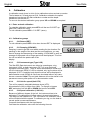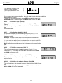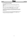
1
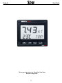
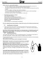
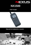
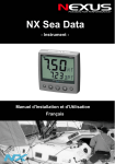
Sea Data
Installation and User Manual
English
Sea Data
English
1
English
Sea Data
This manual is written for Silva Star Sea Data
Edition: May 2004
2
Sea Data
English
1
Introduction............................................................................................................................. 4
1.1
Specifications ................................................................................................................... 4
1.1
Part specifications ............................................................................................................ 4
2
Installation............................................................................................................................... 4
2.1
Installing the instrument ................................................................................................... 5
2.2
Installing transducer ......................................................................................................... 5
2.3
Electrical installation......................................................................................................... 6
3
Function overview .................................................................................................................. 7
3.1 How to use the push buttons ................................................................................................. 7
3.1.1.
Mode / Light button ................................................................................................ 7
3.1.2.
Down button........................................................................................................... 7
3.1.3.
Up button ............................................................................................................... 7
3.1.4.
KEY button............................................................................................................. 7
3.1.5.
Clear ...................................................................................................................... 7
3.2.
Log functions............................................................................................................... 8
3.2.1.
Boat speed ............................................................................................................ 8
3.2.2.
Water temperature................................................................................................. 8
3.2.3.
Trip distance .......................................................................................................... 8
3.2.4.
Total distance ........................................................................................................ 8
3.2.5.
Depth ..................................................................................................................... 8
3.3.
Illumination.................................................................................................................. 8
3.4.
Depth functions (optional) ........................................................................................... 9
3.4.1.
Boat speed ............................................................................................................ 9
3.4.2.
Shallow alarm ........................................................................................................ 9
3.4.3.
Deep alarm ............................................................................................................ 9
3.4.4.
Silencing an alarm ................................................................................................. 9
3.4.5.
Activate / Deactivate an alarm............................................................................... 9
4.
Calibration ....................................................................................................................... 10
4.1.
Enter and exit calibration .......................................................................................... 10
4.2.
Calibration groups ..................................................................................................... 10
4.2.1.
C10 Return (RET)................................................................................................ 10
4.2.2.
C11 Damping (SEA MID)..................................................................................... 10
4.2.3.
C12 Instrument type (Type LOG) ........................................................................ 10
4.2.4.
C13 Unit for speed (Unit KTS) ............................................................................. 10
4.2.5.
C14 Speed calibration (1.20 CAL) ....................................................................... 10
4.2.6.
C15 Unit for depth (Unit M).................................................................................. 11
4.2.7.
C16 Adjusting depth (0.00 ADJ) .......................................................................... 11
4.2.8.
C17 Unit for temperature (Unit °C) ...................................................................... 11
4.2.9.
C18 Temperature adjustment (0°C TMP) ............................................................ 11
4.2.10.
C19 Unit for trip and total distance (Unit NM) ...................................................... 11
4.3.
Customise your display ............................................................................................. 12
5.
Warranty........................................................................................................................... 13
3
English
1
Sea Data
Introduction
Thank you for choosing Star SEA Data.
SEA Data is a digital instrument which will display all necessary data from the SEA. SEA Data is
as standard, a log instrument, providing you information about speed, trip distance, total distance
and water temperature. As an option a depth transducer can be connected, giving you depth, shallow and deep alarm.
The two transducers are connected to the back of the instrument. They are easy to install due to
the colour coded 4-pole jack plugs.
The display is divided into two lines, main function and sub function. The main function displays either speed or depth. The sub functions are divided into two lists, one under each main function.
1.1
Specifications
Speed:
Trip distance:
Total distance:
0-30 knots (0-45 knots with optional high speed paddle wheel)
0-199.99 Nm resetable. Stored in permanent memory.
0-19999.99 Nm non resetable. Stored in permanent memory.
Depth:
Deep alarm:
Shallow alarm:
0.5-150 m
Adjustable
Adjustable
1.1
Part specifications
Star SEA Data is delivered with all mounting material. Make sure all these parts are in the package.
QTY
1
1
1
1
1
1
2
ITEM
Instruction for use
Warranty card
Instrument SEA Data
Instrument cover
Back cover
Screw connector
QTY
1
4
4
1
1
ITEM
Drill template
Mounting screws
Rubber plugs
Red and black power supply cable ( 3m)
Bag with wire protectors and silicon paste
Installation
•
The installation includes 6 major steps:
1. Read the installation and operation manual.
2. Plan where to install the transducer and instrument.
3. Install the transducer, then the instrument.
4. Run the cables.
5. Take a brake and admire your installation.
6. Learn the functions and calibrate your instrument.
•
Before you begin drilling... think about how you can make the installation as neat and simple as your boat will allow. Plan where to position the transducers and instruments. Think
about leaving space for additional instruments in the future.
4
Sea Data
English
A few ”do not’s” you should consider:
− Do not cut cables too short. Allow extra cable length at the instrument so it can be removed for inspection without having to disconnect attached cables.
− Do not place sealant behind the instrument. The instrument gasket eliminates the need for
sealant.
− Do not run cables in the bilge, where water can appear.
− Do not run cables close to the fluorescent light sources, engine or radio transmitting
equipment to avoid electrical disturbances.
− Do not rush, take your time. A neat installation is easy to do.
•
The following material is needed:
Wire cutters and strippers.
Large Philips and small flat head screw driver.
1
Hole saw for the instrument clearance hole 63 mm (2 /2 ”).
11
Hole saw for the transducer fitting, hole: 43 mm (1 /16 ”).
7
2.8 mm ( /64 ”) drill for the mounting holes
Plastic cable ties.
Silicon sealing for use under water (not supplied)
If you are doubtful about the installation, obtain the services of an experienced technician.
2.1
•
Installing the instrument
Place the adhesive drill template in the desired position for the instrument. Drill the four
7
1
screw holes using a 2.8 mm ( /64 ”) drill. Use a 63 mm (2 /2 ”) hole saw to cut the clearance
hole for the instrument connection socket.
Note! Never drill through the instruments four mounting holes as the gasket may be damaged and thus cause leakage. The warranty is not valid for damage caused by drilling
through the mounting holes.
2.2
Installing transducer
The log and depth transducers need to be positioned carefully. The transducer must remain in
the water at all speeds. Turbulent water causing air bubbles must be avoided.
The best position for the log and depth transducers is as close to the centre line of the boat and
as far forward as possible.
The transducer must always remain submerged in the water.
Power boats: The waterline of fast power boats shortens considerably
at high speeds. Therefore the transducer should be placed at 25-30%
from the front line of the waterline at full speed.
Sail boats: Boats with a fin keel must have the transducer located at
least 250 mm (1 ft) but not more than 750 mm (3 ft) in front of the keel,
and no more than 100 mm off the centre. For boats with full-keel it
might be impossible to locate the transducer at the centre line. If the
transducer is off centre, the angle of the paddle wheel should meet the
bow.
The log and depth transducers have the same through hull fitting. De11
cide where to position the transducer and cut a 43 mm (1 /16 ”) hole
with a hole saw. Use sand paper to smooth the surface. Clean the surface around the hole on both sides of the hull. Use silicon paste for under water use and spread it on the through hull fitting.
5
English
Sea Data
Due to different shapes of hulls, the log transducer has to be calibrated on all boats. See 4.2.5
For mounting of depth transducer, see instruction included with transducer.
2.3
Electrical installation
On the back of the instrument there are eight pins; Four for the screw connector for the log
transducer and four for the depth transducer. The connector is colour coded with green, yellow
white and ground sign. Connect the four wires from the log transducer according to the colours
to the connector for LOG, the blank wire is ground. If a depth transducer is connected use the
DEPTH connector for that. Power supply is either connected to green and ground for DEPTH or
LOG.
Green
Yellow
Black
White
Screen
Red
Log transducer and power supply
Log and depth transducers and
power supply
Connect a 5 Ampere fast fuse between the power battery and instrument on the red plus
lead.
6
Sea Data
3
English
Function overview
The SEA Data instrument can work as a log instrument, a depth instrument or as a combined
log/depth instrument. You simply select the type of instrument you want, during calibration.
3.1 How to use the push buttons
3.1.1.
Mode / Light button
This button is used to change between Log mode and Depth mode. One short
press changes between the two modes. To select light levels press mode for
more than two seconds.
3.1.2.
Down button
This button is used to move down in the sub function list or to decrease a value in set mode.
3.1.3.
Up button
This button is used to move up in the sub function list or to increase a value in set mode.
3.1.4.
KEY button
This button is used to lock/unlock a value, to be able to change it.
3.1.5.
Clear
To clear a value or reset trip distance press UP and DOWN together.
7
English
Sea Data
3.2. Log functions
3.2.1.
Boat speed
The main functions displays the boat speed. The unit (Knots or Miles/h)
is selectable during calibration, see 4.2.4.
3.2.2.
Water temperature
To view water temperature press UP or DOWN until the text TMP is
displayed. The water temperature can be displayed in Celsius or Fahrenheit.
To change unit, see 4.2.8.
3.2.3.
Trip distance
To view the trip distance press UP or DOWN until the text TRP is displayed. To clear the trip distance press UP and DOWN together.
Range: 0-199.99 Nm.
3.2.4.
Total distance
To view the total distance press UP or DOWN. Total distance is not
possible to clear and will be stored in the instruments permanent
memory.
Range. 0- 19999.99 Nm.
3.2.5.
Depth
To view depth press UP or DOWN until the text DPT is displayed.
The depth function is only displayed if instrument type is set to
combi. To change instrument type, see 4.2.3.
3.3. Illumination
The LCD and push buttons have three levels of illumination. To turn
on light, press MODE until the text Lit appears. Change level with
UP or Down and lock selection with KEY.
8
Sea Data
English
3.4. Depth functions (optional)
To change between Log and Depth information press MODE. This
function will display depth in metres, feet or fathoms. To change unit
see 4.2.6. A depth sounder measures the time it takes for a sound
pulse transmitted from the transducer, to bounce on the bottom and
be received by the transducer again. The strength of the sound
pulse decreases with the depth and is also affected
by temperature and pollution in the water. A soft bottom with a lot of
vegetation will also decrease the strength of the echo, which can result
in poor reception by the receiver. If no echo is registrated the depth
reading will be three dashes i.e. no echo.
3.4.1.
Boat speed
To view boat speed press UP or DOWN until the text BSP is displayed. The unit (Knots or Miles/h) is selectable in calibration, see
4.2.4.
3.4.2.
Shallow alarm
To get to the shallow alarm function, press UP or DOWN until the
text
SHALLOW is displayed. To change the alarm value, unlock with KEY,
increase/decrease the value with UP/DOWN, move to the next figure
with MODE button and lock the value again with KEY.
3.4.3.
Deep alarm
To get to the deep alarm function press UP or DOWN until the text
DEEP is displayed. To change the alarm value, unlock with KEY,
increase/decrease the value with UP/DOWN, move to next figure
with MODE button and lock the value
again with KEY. The alarm is activated.
3.4.4.
Silencing an alarm
If a shallow alarm limit is reached the instrument will display depth on
the top row
and the alarm limit flashing on the bottom row. To silence the alarm
press any
button or steer the boat to deeper water. The alarm will be automatically
activated
again if the boat is taken to deeper water ( 2 m more than the limit).
3.4.5.
Activate / Deactivate an alarm
To activate / deactivate an alarm, go to the alarm function an press
UP and
DOWN together. If an alarm is active the present alarm value is displayed
together with the text SHA or DEP. If the alarm is deactivated the text
SHALLOW
or DEEP is displayed instead. The alarm value is stored in the memory
even if
the alarm is deactivated.
9
English
4.
Sea Data
Calibration
In calibration mode, there is a list of nine calibration values and set up modes.
The list starts at C10 and stops at C18. Calibration related to the speed
transducer has the text ST after calibration number and the depth
transducer has the text DT.
To move to the desired calibration group press UP and DOWN as required.
4.1. Enter and exit calibration
To enter the calibration mode press KEY until the text C10 RET appears.RET stands for return.
To exit calibration press KEY in C10 RET (return).
4.2. Calibration groups
4.2.1.
C10 Return (RET)
To exit calibration press KEY in this when the text RET is displayed.
4.2.2.
C11 Damping (SEA MID)
Damping is used to get the most stable reading for the situation. Depending on the weight of the boat and the sea conditions, you may
want to change the dampening of the reading. If SEA MAX is used, an
average of the speed over a longer period will be displayed. This function will not effect the update rate of the
display.
4.2.3.
C12 Instrument type (Type LOG)
The Star SEA Data instrument can either be operating as a log
instrument (LOG), a depth instrument (DPT) or as a combined
log/depth instrument (ALL). There is also a demonstration mode built
into the instrument (DEM). If LOG is selected, only log functions will be
displayed. If DPT is selected only depth functions will be displayed.In
demonstration mode (DEM) all values are simulated without any transducers connected. Note! Trip and total distance will not be stored in the
permanent memory after power off in demonstration mode.
4.2.4.
C13 Unit for speed (Unit KTS)
The unit for speed is selectable between knots (KTS),
kilometres/hour (K/h) or Miles /hour (M/h). To change unit press
KEY and select unit with UP or DOWN and confirm with KEY.
4.2.5.
C14 Speed calibration (1.20 CAL)
Because of different shapes of the hull, the instrument has to be
calibrated. This calibration will effect speed, trip and total distance.
The range for the calibration is 1.00-1.99 where The calibration value
will be multiplied with the speed. To calibrate your log, run the boat at
normal speed a measured distance.
Compare the distance with the trip distance.
Calculate the calibration value with the following formula:
10
Sea Data
True distance from sea chart
Log trip counter distance
The current calibration value
New calibration value
English
T
L
C
N
If you suspect that there is water flow, drive the boat in both directions and divide
the trip distance by two.
To enter the new calibration value press KEY increase/decrease with
UP/DOWN, move to the next figure with MODE and confirm with KEY.
4.2.6.
C15 Unit for depth (Unit M)
The unit for depth is selectable between metres (M), feet (FT) or
fathoms
(FA). To change unit press KEY and select unit with UP or DOWN
and
confirm with KEY.
4.2.7.
C16 Adjusting depth (0.00 ADJ)
It is possible to adjust the depth reading plus/minus 99.9 m. This
feature makes it possible to get the reading from either the keel or
the water surface.
Example: Your boat has a draft of two metres and the transducer is
mounted one half metre below the water surface.
1. If you want the reading from the water surface you have to add 0.5 m
2. If you want the reading from the keel you have to subtract 1.5 m
Note! Calibration should be carried out in the same unit chosen for display.
4.2.8.
C17 Unit for temperature (Unit °C)
The unit for temperature is selectable between Celsius (°C) or
Fahrenheit (°F). To change unit press KEY and select unit with UP
or DOWN and confirm with
KEY.
4.2.9.
C18 Temperature adjustment (0°C TMP)
The temperature reading can be adjusted for accurate reading
plus/minus nine
degrees.
4.2.10.
C19 Unit for trip and total distance (Unit NM)
The unit for distance is selectable between Nautical Miles (NM), Kilometres
(KM) and Miles (MI). To change unit press KEY and select unit with
UP or DOWN and confirm with KEY.
11
English
Sea Data
4.3. Customise your display
The two main functions have one ”empty” sub function. One sub function from the
other main function group can be moved into this empty space. For example,
the trip distance can be moved to the depth group. To do that, go to the
trip
function and press KEY and MODE together, the display is flashing.
Go to the depth functions by pressing MODE and lock with KEY.
It is possible to move two functions, one under speed and one under depth.
The last customised display is the display the instrument starts up in,
after power on.
If you want the instrument to start up displaying speed and trip after power on
go to the trip function under speed and press KEY and MODE together.
The display will be flashing, lock with KEY.
12
Sea Data
5.
English
Warranty
13
English
Sea Data
14
English
Copyright ©:
Silva Sweden AB
Kuskvägen 4, 191 62 Sollentuna, Sweden
Tel: +46 -(0) 8 - 623 43 00. Fax: +46 -(0) 8 - 92 76 01
www.silva.se
15
22172-3 Edition 2
Sea Data