1
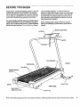
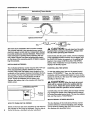
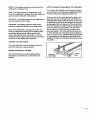
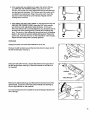
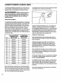
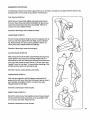
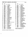
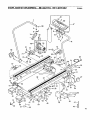
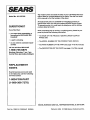
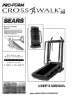
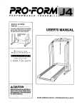
EX PANSE
SEARS
500
Model No. 831.297432
Serial No.
The serial number can be found in
the locationshown below. Write the
serial number in the space above.
Serial Number
Decal
Ex
EC_
i[€,lll
_- F_ _
U
:Bit
I P
I S
M
in
I_
I_
Ro|
N
T
_. !-1
HF---LPLINE!
_Y:-.800- 736-
6879
_CAUTION
Read all precautions and instructions in this manual before using
this equipment. Keep this manual
in a safe place for future reference.
OWNER'S MANUAL
SEARS, ROEBUCK AND CO., HOFFMAN ESTATES, IL 60179
I
FULL 90 DAY WARRANTY
For 90 days from the date of purchase, if failure occurs due to defect in matedal or workmanship in this
SEARS TREADMILL EXERCISER, contact the nearest SEARS Service Center throughout the United
States and SEARS will repair or replace the TREADMILL EXERCISER, free of charge.
This warranty does not apply when the TREADMILL EXERCISER is used commemially or for rental purposes.
This warranty gives you specific legal rights, and you may also have other rights which vary from state
to state.
SEARS, ROEBUCK AND CO., DEPT. 817WA_ HOFFMAN ESTATES, IL 60179
2
EXPANSE
5
O
O
M
TABLE OF CONTENTS
FULL 90 DAY WARRANTY
...................................................................
2
IMPORTANT PRECAUTIONS .................................................................
BEFORE YOU BEGIN .......................................................................
4
5
ASSEMBLY ...............................................................................
OPERATION AND ADJUSTMENT
.............................................................
6
7
TROUBLE-SHOOTING AND STORAGE ........................................................
CONDITIONING GUIDELINES ............................................................
PART LIST ...............................................................................
EXPLODED DRAWING .....................................................................
ORDERING REPLACEMENT PARTS ..................................................
_k WA RNING:
10
_..12
14
15
Back Cover
Before beginning this or any exercise program, consult your physician. This is
especially important for persons over the age of 35 or persons with pre-existing health problems. Read all
instructions before using. SEARS assumes no responsibility for personal injury or property damage sustained by or through the use of this product.
3
IMPORTANT
PRECAUTIONS
WARNING:
To reduce the risk of burns, fire, electric shock or injury to persons, read the following Important precautions and information before operating the treadmill.
It is the responsibility of the owner to ensure
that all users of this treadmill are adequately Informed of all warnings and precautions.
.
Use the treadmill only as described in this
manual.
2.
.
.
.
Q
7.
.
9.
Place the treadmill on a level surface, with
eight feet of clearance behind it. Do not place
the treadmill on any surface that blocks air
openings. To protect the floor or carpet from
damage, place a mat under the treadmill.
Keep the treadmill indoors, away from moisture and dust. Do not put the treadmill in a
garage or covered patio, or near water.
Do not operate the treadmill where aerosol
products are used or where oxygen is being
administered.
Keep small children and pets away from the
treadmill at all times.
The treadmill should be used only by persons
weighing 250 pounds or less.
Never allow more than one person on the
treadmill at a time.
When connecting the power cord (see HOW TO
PLUG IN THE POWER CORD on page 7), plug
the power cord into a surge protector (not included) and plug the surge protector into a
grounded circuit capable of carrying 15 or
more amps. No other appliance should be on
the same circuit.
10. Use only a UL-IIsted surge protector, rated at
15 amps, with a 14-gauge cord of five feet or
less in length. Do not use an extension cord.
12. Never move the walking belt while the power is
turned off. Do not operate the treadmill if the
power cord or plug is damaged, or if the treadmill is not working properly. (See BEFORE
YOU BEGIN on page 5 If the treadmill is not
working properly.)
13. Wear appropriate exercise attire when using
the treadmill. Do not wear loose clothing that
could become caught in the treadmill. Athletic
support clothes are recommended for both
men and women. Always wear athletic shoes.
Never use the treadmill with bare feet, wearing
only stockings, or in sandals.
14. Never start the treadmill while you are standing
on the walking belt. Always hold the handrails
while using the treadmill.
15. The treadmill is capable of high speeds. Adjust
the speed In small increments to avoid sudden
jumps in speed.
16. To reduce the possibility of the treadmill overheating, do not operate the treadmill continuously for longer than I hour.
17. Never leave the treadmill unattended while it is
running. Always remove the key when the
treadmill is not in use.
18. Never insert any object into any opening.
19. Inspect and tighten all parts on the treadmill
every three months.
20. Always unplug the power cord before performing the maintenance and adjustment procedures described in this manual. Servicing other
than the procedures in this manual should be
performed by an authorized service representative only.
11. Keep the power cord and the surge protector
away from heated surfaces.
SAVE THESE INSTRUCTIONS
4
BEFORE YOU BEGIN
Thank you for selecting the SEARS LIFESTYLEFP EXPANSE 500 treadmill. The EXPANSE 500 treadmill
blends advanced technology with innovative design to
let you enjoy an excellent form of cardiovascular exercise in the convenience and pdvacy of your home.
For your benefit, read this manual carefully before
using the treadmill. If you have additional questions,
please call our toll-free HELPLINE at 1-800-736-6879,
Monday through Saturday, 7 a.m. until 7 p.m. Central
Time (excluding holidays). To help us assist you,
please note the product model number and serial number before calling. The model number of the treadmill
is 831.297432. The serial number can be found on a
decal ,_ttached to the treadmill (see the front cover of
this manual for the location).
Before reading further, please review the drawing
below and familiarize yourself with the parts that are
labeled.
FRONT
Walking Belt
Foot Rails
Padded Walking
Platform
Power Cord
BACK
RIGHT SIDE
Rear Roller
Adjustment Bolts
Note: The incline leg pad may mark some types of linoleum. Mild household cleaning agents will remove any marks.
5
ASSEMBLY
Set the treadmill in a cleared area and remove all packing matedals. Do not dispose of the packing materials until
assembly is completed.
THE FOLLOWING
TOOLS
and your own adjustable
ARE REQUIRED
wrench
_
FOR ASSEMBLY:
The Included
7/32" allen wrench
.
1. Raise the Right Handrail (12) to a vertical position. Align the
hole in the lower end of the Right Handrail with the h01e in the
side of the Frame (36). Insert one of the three 3/8" x 2" Bolts
(28) into th e Right Handrail, and tighten the Bolt into the Frame.
Tighten the Bolt that is already in the Right Handrail.
Tighten
Press the Right Handrail Cap (27) onto the lower end of the
Right Handrail (12). Note: It may be necessary to push the 12"
Cable Loom (10) into the Right Handrail.
2. Using the 7/32" Allen Wrench (9), loosen the Handrail Bolt that is
under the Console (6). Rotate the Console to the position
shown.
2
1
38
See the inset drawing. If there is a cable tie through the Handrail
(1) and Handrail Cage Nut (38), cut it. Make sure that the Cage
Nut is inserted into the hole in the underside of the Handrail.
Insert the upper end of the Left Handrail (1) into the left side of
the Console (6). Insert a Handrail Bolt (2) into the bottom of the
Console and the Left Handrail (1). Finger tighten the Handrail
Bolt.
3. Align the holes in the lower end of the Left Handrail (1) with the
holes in the treadmill Frame (36). Tighten a 318" x 2" Bolt (28)
into each hole.
Press the Left Handrail Cap (68) onto the lower end of the Left
Handrail (1).
See step 2. Using the 7/32" Allen Wrench (9), tighten the two
Handrail Bolts (2) under the Console (6).
28
1
36
4. Remove the paper backing from the Wrench Clip (16). Press the
Wrench Clip onto the Right Rear Endcap (59) in the indicated location. Press the 3/16" Allen Wrench (58) into the Wrench Clip.
Make sure that all parts are tightened before using the treadmill.
Note: To protect the floor or carpet from damage, place a mat
under the treadmill.
_59
16
6
OPERATION AND ADJUSTMENT
THE PERFORMANT LUBE TM WALKING BELT
electric shock. This product is equipped with a cord
having an equipment-grounding conductor and a
grounding plug. Plug the power cord into a surge
protector, and plug the surge protector into an appropriate outlet that is properly installed and
grounded In accordance with all local codes and
ordinances.
Your treadmill features a walking belt coated with
PERFORMANT LUBE TM, a high-performance lubdcant.
IMPORTANT: Never apply silicone spray or other
substances to the walking belt or the walking platform. They will deteriorate the walking belt and
cause excessive wear.
HOW TO PLUG IN THE POWER CORD
DANGER:
improper
connection
of the equipment-grounding conductor can
result in an increased risk of electric shock.
This product is for use on a nominal 120-volt circuit,
and has a grounding plug that looks like the plug illustrated in drawing I below. A temporary adapter that
looks like the adapter illustrated in drawing 2 may be
used to connect the surge protector to a 2-pole receptacle as shown in drawing 2 if a propedy grounded outlet is not available.
The temporary adapter should be used only until a
propedy grounded outlet (drawing 1) can be installed
by a qualified electddan.
Check with a qualified electrician or serviceman if you are in doubt as to whether the
product is properly:grounded. Do not modify
the plug provide d with the product---if it will
'not fit the outle t havea 'proper outlet installed by a qualified electrician.'
The graen-colorad rigid ear, lug, or the like extending
from the adapter must be connected to a permanent
ground such as a properly grounded outlet box cover.
Whenever the adapter is used it must be held in place
by a metal screw. Some 2-pole receptacle outlet box
covers are not grounded. Contact a qualified electrician to determine if the outlet box Cover Is
grounded before using an adapter.
Your treadmill, like any other type of sophisticated
electronic equipment, can be seriously damaged by
sudden voltage changes in your home's power,
Voltage surges, spikes, and noise interference can result from weather conditions or from other appliances
being turned on or off.
To decrease the possibility of your tread1
j Grounded Outlet Box
mill being damaged,
always use a surge
protector (not in/ Grounding Pin
cluded) with your
treadmill.
"_unding
Surge protectors are
sold at most hardware
stores and department
stores. Use only a ULlisted surge protector,
rated at 15 amps, with a
14-gauge cord of five
feet or less in length.
This product must be
grounded, If it should
malfunction or break
down, grounding provides a path of least resistance for electric current to reduce the dsk of
Treadmill Power Cord-..
Plug
3rounded Outlet
__
,_/Grounded
,1
Outlet Box
Adapter
,_
Grounding Pin
Plug
Surge Protector
DIAGRAMOFTHECONSOLE
Motivational
SPEED
Fitness
I
TIME
Monitor
DISTANCE
CALORIES
ON/_
Speed ¢
0
Key
The heart of the treadmill is the innovative console.
The console features a key-operated power switch,
electronic speed control and four independent displays
to provide continuous exercise feedback. Please read
these instructions carefully before operating the console. Note: If there is a sheet of protective plastic
on the face of the console, peel it off before operating the console.
INSTALLING
BATTERIES
The motivational fitness monitor requires two "AA" battedes (not included); alkaline batteries are recommended. Slide open the battery cover located on the
underside of the console. Remove the battery clip from
the console. Find the markings inside the battery clip
showing which direction the batteries should be
turned. Press the battedes into the battery clip.
Replace the battery clip in the console and close the
battery cover.
Underside of Console
•
dinJ"
I
Battery
._,J
___J
- Cover
HOW TO TURN ON THE POWER
Stand on the foot rails of the treadmill. Do not stand on
the endcaps or they may be damaged. Find the clip attached to the key, and clip it onto your waistband.
"'--["'
CAUTION:
Do not stand on the walk-
ing belt when turning on the power. Always wear
the clip while operating the treadmill.
Insert the key into the power switch. The four displays
of the motivational fitness monitor will not appear until
the ON/CLEAR button is pressed, or the walking belt
begins to move (see CONTROLLING THE SPEED
below). Note: If batteries were just installed, the four
displays will already appear.
CONTROLLING THE SPEED
To start the walking belt, first turn the speed control
knob to "STOP/RESET." Then, turn the knob slowly
clockwise until the walking belt begins to move at slow
speed. Do not let your feet touch the walking belt when
standing on the foot rails.
A, CAUTION:
After the knob is turned,
there will be a pause before the walking belt begins to move. Adjust the speed slowly until you
are familiar with the operation of the treadmill.
Carefully step onto the walking belt and begin exercising. Change the speed of the walking belt as desired
by turning the speed control knob. To stop the walking
belt, turn the knob to "STOP/RESET."
MOTIVATIONAL
FITNESS MONITOR
The four displays of the motivational fitness monitor
provide continuous exercise feedback. The displays
can be reset by pressing the ON/CLEAR button. The
four displays are descdbed below:
SPEED--This display shows the current speed of the
walking belt, in miles per hour.
TIME--This display shows the elapsed time. Note:
When the walking belt is stopped, the TIME display will
go into a pause mode after a few seconds.
DISTANCE--This display shows the total distance that
you have walked or run, in miles.
CALORIES--This display shows the approximate
number of nutritional Calories that you have burned.
Note: If the walking belt is stopped and remains stationary for about four minutes, the four displays of the
motivational fitness monitor will be reset and will
darken, although the power will remain on. The four
displays will appear again when the ON/CLEAR button
is pressed, or the walking belt is restarted.
HOW TO CHANGE THE INCUNE OF THE TREADMILL
The incline of the treadmill can be changed by raising
or lowering the back end. Before changing the incline,
remove the key and unplug the power cord.
Place one foot on the incline leg near the sticker, and
grasp the.rear roller with beth hands, CAUTION: Do
not place your hands under the frame, or they may
be pinched. Do not lift on the endcaps or they may
be damaged. When the back end of the treadmill is in
the lowest position, the incline is about 10%. Raise the
back end until it clicks into position..The inclinewill
then be about 5%. Raise the back end again until it
clicks into position. The inclinewill then be about 3%.
To lower the back end, first raise it past the highest position, and then lower it. CAUTION: Before exercising
on the treadmill, push slightly on the back of the :
treadmill to make sure that the incline leg Is locked
in position.
TURNING OFF THE POWER
To turn off the power, remove the key from the console. Store the key in a secure location.
PADDED WALKING PLATFORM
The treadmill features a padded walking platform
that adds to your comfort as you exercise on the
treadmill.
9
TROUBLE,SHOOTING
AND STORAGE
Most treadmill problems can be solved by following the simple steps below. Find the symptom that applies, and follow the steps listed. If further assistance is needed, call our toll-free HELPLINE at 1-800-7366879, Monday through Saturday, 7 a.m. until 7 p.m. Central Time (excluding holidays).
1. SYMPTOM:
THE POWER DOES NOT TURN ON
a. Make sure that the power cord is plugged into a surge protector, and that the surge protector is plugged into
a propedy grounded outlet. (See HOW TO PLUG IN THE POWER CORD on page 7.) Use only a UL-listed
surge protector, rated at 15 amps, with a 14-gauge cord of five feet or less in length.
b. After the power cord has been plugged in, make sure that the key is fully inserted into the console. (See
HOW TO TURN ON THE POWER on page 8.)
c. Check the circuit breaker located on the treadmill near the
power cord. If the switch protrudes as shown, the circuit
breaker has tripped. To reset the circuit breaker, wait for five
minutes and then press the switch back in.
Tripped
_
I Reset
2. SYMPTOM: THE POWER TURNS OFF DURING USE
a. Check the circuit breaker located on the treadmill near the power cord. If the circuit breaker has tripped (see
the drawing above), wait for five minutes and then press the switch back in.
b. Make sure that the power cord is plugged in.
c. Remove the key from the console. Reinsert the key fully into the console.
3. SYMPTOM: THE WALKING BELT SLOWS WHEN WALKED ON
a. Use only a UL-listed surge protector, rated at 15 amps, with a 14-gauge cord of five feet or less in length.
b. If the walking belt is overtightened, treadmill performance may
decrease and the walking belt may be permanently damaged.
Remove the key and UNPLUG THE POWER CORD. Using the
3/16" allen wrench, turn both rear roller adjustment bolts counterclockwise, 1/4 of a turn. When the walking belt is properly
tightened, you should be able to lift each side of the walking
belt 3-4 inches off the walking platform. The center of the walking belt should just touch the walking platform. Be careful to
keep the walking belt centered. Plug in the power cord, insert
the key and run the treadmill for a few minutes. Repeat until the
walking belt is properly tightened.
Rear Roller Adjustment Bolts
c. If the walking belt still slows when walked on, please call our toll-free HELPLINE.
4. SYMPTOM: THE WALKING BELT IS OFF-CENTER OR SLIPS WHEN WALKED ON
a. If the walking belt has shifted to the left, first remove the key
and UNPLUG THE POWER CORD. Using the 3/16" allen
wrench, turn the left rear roller adjustment bolt clockwise, and
the right bolt counterclockwise, 1/4 of a turn each. Be careful
not to overtighten the walking belt. Plug in the power cord, insert the key and run the treadmill for a few minutes. Repeat
until the walking belt is centered.
10
b. If the walking belt
has shifted to the right, first remove the key
and UNPLUG THE POWER CORD. Using the 3/16" allen
wrench, turn the left rear roller adjustment bolt counterclockwise,
and the right bolt clockwise, 1/4 of a turn each. Be careful not to
overtighten the walking belt. Plug in the power cord, insert the
key and run the treadmill for a few minutes. Repeat until the
walking belt is centered.
c. If the walking belt slips when walked on, first remove the key and
UNPLUG THE POWER CORD. Using the 3/16" allen wrench,
turn both rear roller adjustment bolts clockwise, 1/4 of a turn.
When the walking belt is correctlytightened, you should be able to
lift each side of the walking belt 3-4 inches off the walking platform. The center of the walking belt should just touch the walking
platform. Be careful to keep the walking belt centered. Plug in the
power cord, insert the key and run the treadmill for a few minutes.
Repeat untilthe walking belt is propedy tightened.
STORAGE
Unplug the power cord when the treadmill is not in use.
Remove the left handrail cap and the two bolts from the lower end of
the left handrail (see drawing 1).
Using the 7132"allen wrench, remove the bolt from the upper end of
the left handrail (see drawing 2). Slide the handrail out and lay it on
the treadmill.
Remove the right handrail cap and the bolt from the lower end of the
right handrail. Loosen the other bolt in the handrail (see drawing 3).
Lay the right handrail on the treadmill.
It is recommended that the treadmill be covered during extended periods of storage.
Remove
11
CONDITIONING
GUIDELINES
The following guidelines will help you to plan your exercise program. Remember that proper nutrition and
adequate rest are essential for successful results.
WARNING:
To measure your heart rate, stop exercising and place
two fingers on your wrist as shown below.
Before beginning this or
any exercise program, consult your physician.
This Is especially important for individuals over
the age of 35 or Individuals with pre-existing
health problems.
EXERCISE INTENSITY
To maximize the benefits of exercising, it is important
to exercise with the proper intensity. The proper intensity level can be found by using your heart rate as a
guide. Foreffective aerobic exercise, your heart rate
should be maintained at a level between 70% and
85% of your maximum heart rate as you exercise.
This is known as your training zone. You can find your
training zone in the table below. Training zones are
listed for both unconditioned and conditioned persons
according to age.
AGE
UNCONDITIONED
TRAINING ZONE
(BEATS/MIN)
CONDITIONED
TRAINING ZONE
(BEATS/MIN)
20
138-167
133-162
25
136-166
132-160
30
135-164
130-158
35
134-162
129-156
40
132-161
127-155
45
131-159
125-153
50
129-156
124-150
55
127-155
122-149
60
126-153
121-147
65
125-151
119-145
70
123-150
118-144
75
122-147
117-142
80
120-146
115-140
85
118-144
114-139
During the first few months of your exercise program,
keep your heart rate near the low end of your training
zone as you exercise. After a few months, your heart
rate can be increased gradually until it is near the middle of your training zone as you exercise.
12
Take a six-second heartbeat count, and multiply the
result by 10 to find your heart rate. For example, if
your six-second heartbeat count is 14, your heart rate
is 140 beats per minute. (A six-second count is used
because your heart rate will drop rapidly when you
stop exercising.) Adjust the intensity of your exercise
until your heart rate is at the proper level.
WORKOUT GUIDELINES
Each workout should consist of three basic parts: a
warm-up, 20 to 30 minutes of training zone exercise,
and a cool-down.
Warming up prepares the body for exercise by increasing circulation, delivering more oxygen to the
muscles and raising the body temperature. Begin
each workout with 5 to 10 minutes of stretching and
light exercise to warm up.
Next, increase the intensity of your exercise to raise
your heart rate to your training zone for 20 to 30 minutes. Breathe regularly and deeply as you exercise-never hold your breath.
Finish each workout with 5 to 10 minutes of stretching
to cool down. Stretching after exercise is very effective for increasing flexibility.
To maintain or improve your condition, complete three
workouts each week, with at least one day of rest between workouts. After a few months of regular exercise, you may complete up to five workouts each week,
if desired.
The key to success is to make exercise an enjoyable
part of your everyday life.
SUGGESTED STRETCHES
The following stretches can provide a good warm-up or cool-down. Correct form for each stretch is shown in the
drawings below. Move slowly as you stretch---never bounce.
TOE TOUCH STRETCH
Stand with your knees bent slightly and slowly bend forward
from your hips. Allow your back and shoulders to relax as you
reach down toward your toes as far as possible. Hold for 15
counts, then relax. Repeat 3 times.
Stretches: Hamstrings, back of knees and back.
HAMSTRING STRETCH
Sit with one leg extended. Bring the sole of the opposite foot toward you and rest it against the inner thigh of your extended
leg. Reach toward your toes as far as possible. Hold for 15
counts, then relax. Repeat 3 times for both legs.
Stretches: Hamstrings, lower back and groin.
CALF/ACHILLES STRETCH
With one leg in front of the other, reach forward and place your
hands against a wall. Keep your back leg straight and your
back foot fiat on the floor. Bend your front leg, lean forward and
move your hips toward the wall. Hold for 15 counts, then relax.
Repeat 3 times for both legs. To cause further stretching of the
achilles tendons, bend your back leg as well.
Stretches: Calves, achilles tendons and ankles.
QUADRICEPS STRETCH
With one hand against a wall for balance, reach back and
grasp one foot with your other hand. Bring your heel as close to
your buttocks as possible. Hold for 15 counts, then relax.
Repeat 3 times for both legs.
Stretches: Quadriceps and hip muscles.
INNER THIGH STRETCH
Sit with the soles of your feet together and your knees outward.
Pull your feet toward your groin area as far as possible. Hold
for 15 counts, then relax. Repeat 3 times.
Stretches: Quaddceps and hip muscles.
13
PART LIST--Model
14
R0296A
Description
Key
No.
Part
No.
1
2
4
1
1
1
1
1
1
2
5
1
1
12
1
2
1
1
4
1
1
1
1
3
1
2
1
4
2
14
2
Left Handrail
Handrail Bolt
Cage Nut
Key/Clip
Speed Control Knob
Console
Wire Harness
Console Plate
7/32" Allen Wrench
12"Cable Loom
Console Screw
Right Handrail
Pulley Cover
Endcap Screw
Front Roller/Pulley
Adhesive Clip
Reed Switch
Extension Wire
Wire Clip
Circuit Breaker
Grommet
Power Cord
Front Roller Adj. Bolt
Adjustment Washer
Front Right Endcap
Motor Nut
Right Handrail Cap
3/8" x 2" Bolt
Wheel Bolt
Small Screw
Front Wheel
45
46
47
48
49
50
51
52
53
54
55
56
57
58
59
60
61
62
63
64
65
66
67
68
69
70
71
72
73
74
75
122363
122871
016057
124423
013547
124292
012108
014105
123627
116980
123961
116927
116926
123355
123992
105444
123991
109788
100691
124146
124380
125323
031238
123921
122812
014117
120867
122632
112825
118017
100994
6
2
1
10
1
1
2
1
1
2
4
1
2
Front Wheel Nut/Incline Leg Nut
Belt Guide
Safety Cover
Safety Cover Screw
Frame
Right Foot Rail
Handrail Cage Nut
Walking Belt
4" Wire Tie
Incline Leg Bolt
Incline Leg Spring
Motor Pivot Bolt
Incline Leg Latch
76
77
78
79"
80
81
#
#
#
#
124100
117992
108080
124151
111467
127733
115868
123898
115868
128018
Key
No.
Part
No.
Qty.
1
2
3
4
5
6*
7
8
9
10
11
12
13
14
15
16
17
18
19
20
21
22
23
24
25
26
27
28
29
30
31
123635
122137
111869
119038
110000
124150
123897
123637
045017
103643
013141
123633
123993
013322
124147
016028
118153
118195
054023
109382
124695
124669
112609
014127
123994
105477
123922
013601
117806
120630
123647
32
33
34
35
36
37
38
39
40
41
42
43
44
012056
124318
123628
013162
NSP
124148
111430
124145
016029
124422
124565
107503
123666
Specifications
No. 831.297432
are subject to change without notice.
Qty.
Description
1
1
2
2
1
1
1
4
1
2
2
1
1
1
Controller Plate
Controller
8" wire Tie
Incline Bolt
Motor Lock Bolt
Pulley Cover Bracket
Motor Swivel Nut
Incline Leg Washer
Incline Leg
Incline Leg Er'tdcap
Incline Leg Pad
Cable Tie Clip
Cable Tie
3/16" Allen Wrench
1
2
1
1
8
Right Rear Endcap
Rear Roller Adj. Bolt
Left Rear Endcap
Rear Roller
Platform Screw
1
8
1
1
1
1
1
1
1
1
1
2
1
Padded Walking Platform
Endcap U-Nut
Left Foot Rail
Choke
Left Handrail Cap
Motor Tension Washer
Star Washer
Motor Tension Nut
Motor Mount Bracket
Pulley/Flywheel/Fan
Motor Belt
Motor Bolt
Motor
1
4
1
1
Safety Cover Plug
Choke Screw/Plate Screw
Motor/Pulley/Flywheel/Fan
Potentiometer
1
1
1
1
1
Battery Cover
Pot. Wire Extension
White 2 Wire Jumper
12" Pot Extension Wire
Owner's Manual
* Includes all the parts shown in the box.
# These are non-illustrated parts.
EXPLODED DRAWING--Model
No. 831.297432
RO296A
81
8O
11
2
12
13
51
68
22
70
49
39
\
27
37
14
14
34
31
35
33
3O
29
61
52
16
55
48
54
78
404--_
15
S£/ARS
The model number and serial number of your EXPANSE 500 treadmill are listed on a decal attached to the frame. See the front cover
of th s manua to find the location of the decal.
Model No. 831.297432
All replacement parts are available for immediate purchase or
special order when you visit your nearest SEARS Service Center.
To request service or to order parts by telephone, call the toll-free
numbers listed at the left.
QUESTIONS?
If you find that:
• you need help assembling or
operating the EXPANSE 500
treadmill
• a part is missing
When requesting help or service, or ordering parts, please be prepared to provide the following information:
• The NAME OF THE PRODUCT (SEARS LIFESTYLEFP EXPANSE 500)
• The MODEL NUMBER OF THE PRODUCT (831.297432)
• or you need to schedule repair
service
call our toll-free HELPLINE
1-800-736-6879
• The PART NUMBER OF THE PART (see page 14 of this manual)
• The DESCRIPTION OF THE PART (see page 14 of this manual)
Monday-Saturday,
7 am-7 pm
Central Time (excluding holidays)
REPLACEMENT
PARTS
If parts become worn and need
to be replaced, call the following
ton-free number
1-800-FON-PART
(1-800-366-7278)
SEARS, ROEBUCK AND CO., HOFFMAN ESTATES, IL 60179 USA
Pa_ No. 128018
F00229AC
RO296A
Printed in USA
© 1996 Sears, RoebLJckand Co.