1
®
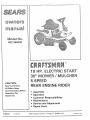
10 HP° ELECTRIC START
30" MOWER / MULCHE
5
REAR ENGU E IDER
CAUTION:
Read And
Follow
All Safety Rules
And Instructions
Operating
This
Equipment.
Before
o Assembly
• Operation
• Customer
Responsibilities
= Maintenance
• Service
= Repair
F-92533
11-22-91
and Adjustment
Parts
Sears, Roebuck and Co,, Chicago,
tL. 60684
U,SA,
Printedin USA
SAFETY
Safe
Operation
As Recommended
This cutting
safety
machine
GENERAL
1
is capable
instructions
in serious
understand
before
starting
and
follow
responsible
all instructions
2
Only allow
3
Clear the area of objects
4
Be sure the area is clear of other people
5
Never
6
Disengage
power
look
and behind
carry
down
adults
Institute
to the operator
objects.
Failure to observe
the following
or bystanders°
to the mower
before
with
the instructions
wire,
before
etc
Book.
to operate
which
mowing
Slow
9
Never leave a machine
down
before
could
Stop
on the
machine
tbe
engine
and
with
any attachments
the machine
be picked
the machine
up and thrown
if anyone
enters
by the blade
the area
Disengage
11
Stop
the engine
1 2.
Mow
only
13
Do not operate
14
Watch
power
16
Use extra caution
16
Disengage
17
Always
backing
up
Do not mow
in reverse
unless
absolutely
necessary
Always
Do not point discharge
the entire
grass bagger
from the mower
or the mower
at anyone
guard
or at places where
people
may be
in place
with
or good
when
running
when
artificial
whl]e
loading
Always
disengage
the blade(s),
set the parking
brake, stop the engine and
wear
Use care when
pulling
a
Use only
approved
b
Limit
c
Do not
d
Use counterweights
the influence
near or crossing
or unloading
of alcohol
the machine
and shift
into Neutral
when
before
you operate
eye protection
you make
or using
drawbar
when
heavy
hitch
the blade(s)
when
not mowing
or drugs
or when
very tired
using
a trailer
attempting
or truck
to start
the unit to protect
an adjustment
for transporting
the engine
your eyes from foreign
or repair
objects
that can be thrown
to the machine
equipment
points
loads to those you can safely
control
Use care when
or wheel
Disengage
the chute
roadways
or an eye shield when
loads
turn sharply,
or not in use
or unclogging
light
under
clutches
glasses
transporting
the grass bagger
operating
all attachment
Always
when
removing
the machine
wear safety
the engine
dismounting,
to attachment(s)
in daylight
the unit
either
unattended
before
for traffic
discharges
without
before
backing
turning
the key before
10
or any attachments
and while
the mower
the mower
8
remove
familiar
Instruction
passengers.
Do not operate
18
Vehicles
Standards
and feet and throwing
or death
in the
such as rocks, toys,
Be aware of the direction
from
hands
injury
National
OPERATION:
Read,
7
for Riding
by American
of amputating
could result
RULES
Practices
backing
weights
when
suggested
in the Instruction
Book
SLOPE OPERATION:
Slopes
and rough terrain
ALL slopes
Guide"
require
in the
back
are major
extra
caution
of this
book
factors
related
If you cannot
to check
to loss of control
back
for safe
and tip over accidents
up the slope
or if you feel
uneasy
which
on the
ca n result
slope,
in seve re injury or death,
do not
mow
it. See the
"Slope
operation.
DO
1
Mow
up and down
2
Remove
3
Watch
4
Use slow
5
Follow
6
Use extra
7
Keep all movement
8
Avoid
1
2
Do riot turn on slopes unless absolutely necessary, then only turn slowly and gradually downhill, if possible
Do not mow near drop-offs, ditches or embankments A wheel over the edge or an edge caving in could cause a sudden overturn and
obstacles
for holes,
speed
slopes
ruts or bumps.
Choose
the manufacturers
care with
starting
DO
not across,
such as rocks,
limbs,
etc
Uneven
a low enough
terrain
recommendations
grass baggers
or other
on the slopes
slow
or stopping
on a slope
could
overturn
gear so that you will
for wheel
weights
attachments,
and gradual.
the machine
grass can hide
or counterweights
they can change
Do not make
if tires lose traction,
Tall
not have to stop or shift
disengage
sudden
changes
obstacles.
on the slope
to improve
the stability
the blades
while
stability
of the machine
in speed or direction
and proceed
slowty
straight
down
the slope
NOT
an injury or death,
3
Do not mow on wet grass Reduced traction could cause sliding
4.
Do not try to stabilize the machine by putting your foot on the ground
5
Do not use a grass bagger or other rear mounted accessories on steep slopes (greater than 10 °)
F-92533
2
SAFETY
RULES - continued
CHILDREN:
Tragic accidents
mowing
can occur
activity
if the operator
NEVER
assume
that
1
Keep children
2
Be alert
out of the mowing
3
Before
and when
4
Never
carry
children
or any
allow
children
to operate
and turn the engine
backing,
is not alert to the presence
children
will
remain
where
area and in the watchful
off if children
took behind
enter
They
are often attracted
to the machine
and the
sew them
care of an adub
other
than
the operator
the area
and down
passengers_
of chiJdren_ Children
you last
for small
children
may faIt off
and be seriously
injured or interfere
with
the safe
operation
of the
macMne
5
Never
6
Use extra
the machine
care when
approaching
care when
handllng
instruct
bl_nd corners,
children
shrubs,
in the dangers
trees
or other
of the machine
objects
that
may obscure
vision
SERVICE:
1
Use extra
a
Use only
an approved
b
Never remove
gasollne
and other
fuels
Fuels are flammable
and the vapors
are explosive
container
the gas cap or add fuei with the engine running
Allow
the engine to cool for several
minutes
before
refueling
Do
not smoke
c
Never
refuel
the machine
d
Never
store
the machine
indoors
with
fuel
in the tank
or fuel
container
inside
where
there
is an open
flame,
such
as a water
heater
2
Never
3
Keep a[f nuts and bo{ts, especially
start
and nicks
dealer
or run the engine
For safety,
tamper
replace
Never
5
To reduce fire hazards
before
Stop
with
B
the equipment
governor
Grass bagger
parts
9
when
area
Wait
settings
an object
Repair,
with the engine running
or overspeed
are subject
the brake
are sharp
operation
for all movement
and can cut
frequently
to stop before
A
F_92533
operation
the blade(s}
for wear or damage
equipment
such as cracks
blade from an authorized
service
condition
regularly
Clean up oil or fue_ sp_llage Allow
the machine
to
if necessary,
The carburetor
before
re-starting
can be adiusted
with
the engine
running
Do not change
the engine
to wear.
damage
and deterioration,
Frequently
which
could
check components
expose
moving
parts or allow
and replace with manufacturers
objects
to be
recommended
necessary
housing
11
proper
_n good
free of grass, leaves or other debris build-up
if you strike
or repairs
components
blade(s)
Check
their
check
with an original
Keep the equipment
For storage, always make sure the grass bag is empty
Mower
!0
Check
years
Frequently
replaced
storing
and inspect
thrown
devices
keep the machine
nuts tight
must be immediately
the blade every two
the safety
Never make adjustments
the engine
area
the blade attachment
A blade that is bent or damaged
4
cool
inside a closed
Wrap
the blade(a)
or wear
Adjust
and service
as required
servicing
gloves
and use extra
caution
when
any part of the unit
precautions
This symbol indicates:
"Attention!
Look for this symbol
to indicate important
safety
Become Alert! Your Safety Is At Risk."
3
servicing
them
or the blade
Congratulations on your purchase of a Sears Rider It has been
designed, engineered and manufactured to give you the best
possible dependability and performance
If you experience any problems you cannot easily remedy, please
see your nearest Sears Service Department We have competent,
wet! trained technicians and the proper tools to service or repair this
unit
Please read and retain this manual The instructions will enable you
to assemble and maintain your unit properly Always observe the
"Safety Rules"
CUSTOMER
RESPONSIBILITIES
e
Carefully read and follow the rules for safe operation
the unit
•
e
Follow all the assembly instructions Carefully adjust the unit
Know how to operate all standard and aceessary equipment on
the unit Make sure the operator can correctly operate the unit
e
Operate the unit only with guards, shields and other safety
items in place and working correctly
e
Complete all maintenance on the unit Service the unit only with
authorized or approved replacement parts
See the Customer Responsibility / Maintenance Chart
e
Inspect
PRODUCT
SPECIFICATIONS
Craftsman Engine
10 HR
Charging System
3 amperes at 3600 rpm
Fuel TankSIze
3 quarts
Type of Fuel
Unleaded Regular
Oil Capacity
32 ounces
Oil Type
Above 32 degrees SAE 30 or 10W30
Below 32 degrees SAE 5W30
Spark Plug (Gap &030")
Champion J-8C
Sears 71-33312
STD361458
Tire Air Pressure
Front 24 psi
Rear 14 psi
All Gear Transaxle
Five forward speeds and one reverse
Ground Speed Range
Forward 0-43 mph
Reverse 0-2 1 mph
Tilt Seat The seat tilts forward for easy access to the battery
Side Panels
Easily removed for access to the engine
Mower Housing
The full-floating suspension and single blade
give an even cut A removable mulcher plate that lets you mulch the
grass and leaves The lift lever has eight positions from 1-1/2 to 4
inches
Blade Nut Torque
30 foot-pounds (ft-lbs)
RIDING
NOTE: This unit is equipped with an inter nalcombustion engine and
must not be used on or near any unimproved forest-covered,
brush-covered orgrass-covered
land unless the engine's exhaust
system is equippedwith a spark attester meeting applicable local or
state laws (if any) tf a spark attester is used, it must be maintained
in effective working order by the operator
The model number and serial number are found under the
seat on a decal attached to the seat support
In the State of California, the above is required by law (Section 4442
of the California Public Resources Code) Other states may have
simiiar laws Federal laws apply on federal lands. See an Authorized
Service Center for a spark attester for the muffler
MAINTENANCE
LAWN MOWER
Record in the space below the serial number and the date
of purchase of this unit
Model Number:
502,255020
Serial Number:
AGREEMENT
Date of Purchase:
A Sears Maintenance Agreement is available on this unit See the
nearest Sears Store for information
......................
i.¸ii/:
:.:...:: L........................
_::::_ _L_i:M:I ¸T E:D:TW
ON ELECTRIC
Keep these numbers for future reference.
IO_:_:_Y_:A
_R[_:a
START
RIDING
_R¸AN:_
¸_[¸:_i:i¸_:_IEi¸¸_¸:_;_:::
_:_:L:::
:::::_i_
__:i__:__::__:_,:;
_:+:
_;::_:_ _::i_:_:_:_
EQUIPMENT
H
For two 2 years from the date,of purchase, if this riding equipment is manta ned, ubricated and tuned up acco d g
to the instructions in the owners manual Sears will repair or rep ace free of charge, any parts oundto be de ec ve
I I
I::l
in materia, or workmanship
ft
This warranty does not cover:
e
e
e
Expendable items which becorne worn during normal use, such as blades spark plugs, air cleaners and belts
Tire replacement or repair caused by punctures from outside objects, such as nails, thorns, stumps or glass
Repairs necessary because of operator abuse, negligence improper storage or accident or the failure o ma a n
the equipment according to the instructions contained in the owner's manual
I_1
II
I: I
I I
| I
I I
e
Riding equipment used for commercial
I. I
LIMITED
90 DAY WARRANTY
or rental purposes
ON BATTERY
[iI
II
For 90 days from the date of purchase, if any battery included with this riding equipment proves defect ve
ma eral
or workmanship and our testing determines the battery will not hold a charge, Sears will replace the battery at no
I I
I 1
charge
II
WARRANTY
SERVICE IS AVAILABLE BY RETURNING
THE RIDING EQUIPMENT
SERVICE CENTER/DEPARTMENT
IN THE UNITED STATES.
TO THE NEAREST
SEARS
| I
ILI
I t
This warranty gives you specific legal rights, and you may also have other rights which may vary from state to state
.,
F_92533
Sears, Roebuck
and Co. Di731CR-W,
Sears Tower, Chicago,
4
Illinois
60684_
Ii t
/i:...jll
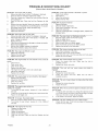
TABLE
SAFETY RULES ....................................................
CUSTOMER RESPONSIBILITIES
..........................
PRODUCT SPECIFICATIONS
................................
OF CONTENTS
MAINTENANCE
2-3
4
4
..............................................
18-24
SERVICE AND ADJUSTMENT
......................
25-29
STORAGE ...........................................................
30
TROUBLE SHOOTING CHART ................................ 31
REPAIR PARTS, MOWER ........................................
32-43
REPAIR PARTS, TRANSAXLE
......................... 44-45
REPAIR PARTS, ENGINE .............................
46-49
ELECTRICAL SCHEMATIC
...................................
50
WARRANTY
..........................................................
4
TABLE OF CONTENTS
............................................
5
INDEX .....................................................................
5
RIDER ATTACHMENTS
.........................................
6
ASSEMBLY
...........................................................
7-11
OPERATION
................................................
12-17
PARTS ORDERING/SERVICE
.................
Back Page
INDEX
A
Adjustments:
glade Engagement Control
......
grake. Drive ......................
Carburetor
........................
Mower Housing. Level .........
Throttle Control Cable ...........
Air Screen
........................
Assembly ...........................................
Attachments
......................................
20
21
25
28
25
23
7 - 11
6
Starting
...................................
Stopping
.......
Storage ................................
Throttle Control ...........................
Trouble Shooting Chart
................
F
Filter. Air ...................................
Fuel .............................
Fuel System Storage .........................
Fuse .............................
29.31
B
Bagging Tips .................
Batter/:
Charge
..................
Clean and Check .......................
Emergency Start .......
install ...................
Storage
......................
Belt:
Motion Drive. Replace ...............
Mower Drive, Adjust
............
Mower Drive, Replace .....................
Routing Check
........................
Blade, Remove and install
..............
glade, Sharpen ...........................
glade Engagement Control:
Adjust ..........................
Operation .......................................
Brake, Check and Adjust Drive
Brake Check and Adjust Transaxle
Brake Pedal Operation
..........
27
20
27
9
19
19
20
14
21
21
12
C
Carburetor Adjust
..................
Charge Batter/ ..............................
Charge Mower Housing To Mulcher
Clutch/Brake Pedal ...................
Controls .................................
Cutting Height
....................
25
8
........ 17
12
12
14, 29
24
15
30
42
L
16
9
22
29
10
30
15
13
30
12 25
31
Lift Lever ...................
Lubdca tion .............................
12
17
M
Maintenance ...........................
18 - 24
Air Filter .....................................
24
Air Screen .............................
23
Batter/
....................................
22
Blade .........................................................
19
Blade Engagement Control .............
Brake ............................................
Clutch ..........................
Engine Oil ...........................................
Lubrication
..................
Muffler, Check ...........
Spark Arrestor ...........
Spark Plug ......................................
Tires ........................
Transaxfe Brake .............................
Maintenance Schedule ........................
Mower Housing:
Clean ........................
Level ..................................................
Remove and install ...............
Mowing and Bagging Tips ..........
20
21
21
23
!8
24
4 24
24
22
21
18
29
28
26
16
O
Oil:
E
Electrical Schematic
.......................
Engine:
Carburetor ............................
Oil. Change
..........................
Oil Level Check ....................
Oil. Type .............................
Operation Speed Chart ......................
F-92533
50
25
23
23
23
13
Check ...................................
Change .............................
Operating Tips .............................
Operation .....................
Lift Lever ............................
Mower Housing
.....................
Mulcher ...................................
Operate On Hills
....................
5
23
23
16
12- 17
12
!4
16
14
Parking Brake ..............
Shift Lever ..................
Start Engine .........................
Stop The Unit ..................
12, 13
12 13
15
13
P
Parking Brake ............................
12
Parts Bag Riding Mower .......................
13
7
R
Replace Motion Drive Belt ...........
Replace Mower Drive Belt ...............
27
27
s
Safety Rules ......................
Seat, Install
.....................................
Service and Adjustment
......
Batter/ Emergency Start ............
Mower Drive Belt ...................
Carburetor
.................................
2- 3
11
25 - 29
29
27
25
Height 0fCut ..................................
29
Level Mower Housing ........
28
Motion Drive Belt
..........
27
Mower Housing, Install .............
26
Mower Housing Remove ................
26
Sharpen. Blade .................................
19
Shift Lever ...................
12 13
Side Panel Remove
.............
22
Slope Guide ...................................
Spark Plug ............................................
Specifications
Product
...............
Speed Control Chart
...........................
Start Engine ..........................
Steering Wheel ...................................
Stop, Riding Mower ...............................
Storage ...........................................
51
24
4
13
15
9
13
30
T
Throttle Control ............................
Throttle Control Cable. Adjust
........
Tire Pressure .................................
Trouble Shooting Chart
.............
Transaxle Brake .......................
Transport ...............................................
14
25
22
31
21
14
w
Warranty
.....................................
Wheel, Align Front
.................
Wiring Schematic
....................
4
29
50
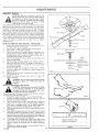
ACCESSORIES
AND ATTACHMENTS
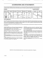
These accessories arrd attachments were available when the unit was purchased. They are also available at most Sears retail outlets, catalog
arrd service centers. Most Sears stores can order these items for you when you provide the model number of your riding mower
ENGINE
SPARK PLUG
MAINTENANCE
MUFFLER
AIR FILTER
GAS CAN
ENGINE OIL
STABILIZER
BLADES
BELTS
PERFORMANCE
Sears offers a wide variety of attachments that fit your riding mower Many of these are listed below with brief explanations of flow they can
help you This list was current at the time of publication; however, it may change in future years- more attachments may be added, changes
may be mode in these attachments, or some may no longer be available or fit your model Contact your nearest Sears store for the
accessories
and attachments
that are available for your unit.
Most of these attachments do not require additional hitches or corrversion kits (those that do are indicated) and are designed for easy attaching
and detaching
GRASS BAGGER lets you collect grass clippings and leaves far a
healthier, nearer looking lawn. Two Grass containers hold 33-gallon
disposable plastic bags and offers 7 bushel capacity
LAWN SWEEPERS
let you collect grass clippings and leaves
CARTS make hauling easy Variety of sizes available
MULCH RAKE/DETHATCHER
loosens soil and flips thatch and
matted leaves to lawn surface for easy pickup. Twenty spring tine
teeth Useful to prepare bare areas for seeding Available for rear
mounting only.
ROLLER for smoother lawn surface. 36-inch wide, 18-inch
diameter water-tight drum holds up to 390-tbs of weight Rounded
edges prevent harmtoturf Adjustable scrape r automatically cleans
drum
SPREADER/SEEDERS
make seeding, fertilizing and weed killing
easy. Bioadcast spreaders are also useful for granular deicers and
sand
CORING AERATOR takes small plugs out of soil to allow moisture
and nutrients to reach grass roots 36-inch swath 24 hardened
2 5-inch steel coring tips 150-1b weight tray
NOTE: Do not use pull-behind
F-92533
AERATOR promotes deep root growth for a healthy lawn. Tapered
2_5-inch steel spikes mounted on 10-inch diameter disc puncture
holes in soil at close intervals to let moisture soak in Steel weight
tray for increased penetration.
SPRAYERS use 12-volt DC electric motor that connects to the
tractor battery or other 12-volt source Includes booms for
automatic spraying when pulling, and hand held wand for spot
spraying
Wand has adjustable spray pattern
For applying
herbicides, insecticides, fungicides and liquid fertilizers
MULCHER CONVERSION KIT turns your ridel into a mulching
mower
attachments
on slopes that are greater than lO-degrees_
6
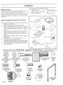
ASSEMBLY
TOOLS
PREPARATION
Before being put in the carton, the u nit was carefully inspected
carton was made to protect the unit dudng shipment
The unit !s completely
assembled
this page These items
contains
the fasteners
these
except
for the items
are in the carton with
to assemble
the unit
shown
YOU
NEED TO ASSEMBLE
1
Adjustable
The
2
3
Open end wrench
Open end wrench
on
4
Blade type
THE
wrench
1/2" - 9/16"
7/1 6" - 1/2"
screwdriver
UNIT
5
Phillips
6
7
Low Tire pressure
Knife
screwdriver
8
Socket
gauge
Set (OpdonaI)
a parts bag which
Find and remove
items
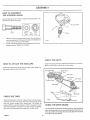
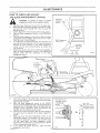
HOW
TO REMOVE
FROM
THE CARTON
8artery
To remove
the unit from
the carton,
follow
the instructions
1
2
Open the top of the ca_on
Remove the wood frame at the top of the carton
3
Remove
the
Remove
the seat and containers
seat
and
boxes
containers
labeled
are
(A) and
(B) from
from
each
the
the carton
covered
with
SteedngWh_
below
carton
NOTE: the
a protective
sleeve
4
The items shown at the right are in a small unmarked
Remove and check each item Remove the small box
box
5
Cut each corner
with
of the carton
from the top to the bottom
a knife
NOTE:
the
See
the
Operation
section
for
the
6
Move
7
Move the lift lever to the HiGH position
CAUTION:
Check the bottom
of the carton
the shift
Remove
8
location
of
controls.
lever to the NEUTRAL
any staples
that
are in the
From the back of the unit, carefully
off the wood
position
path
pull the unit backwards
frame
PARTS
The fasteners
for staples
of the tires
and loose
parts
are shown
BAG-
contents
below,
The fasteners
for
Riding
are shown
Mower
full
size with
the
quantities
in brackets
(),
:'i?i'!?i?!?i?i?!'i'i?i'_?;"
..........
i.i .........
i.
,iiiiiiiiiiiiiiiiii!
(1) Cover, Battery Cable
For Positive Terminal
54148
5/16"-18
15x66
(2) Lockwasher
For Seat
I,D, 5/16"
18x16
15x88
12) Hex Bolt
For Battery Terminals
1/4"-20 x 5/8"
lx38
(3) Carriage Bolt
For Seat Bracket
5/16"-1 B x 3/4"
2x53
(2) Hex Bolt
For Seat
5/16"-18
x 5/8"
1x45
(1) Clamp
For Battery Drain
91565
_ap
!f .r %%
For Battery Drain
Not Ihown
full =izo
(4) Hub Cap
For Wheels
F-92533
(2) Ignition Key
91275
7
Not'lhow_ full
(1) Clamp,
Battery
56205Z
ASS E M B LY
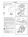
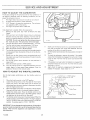
HOW TO PREPARE AND
CHARGE THE BATTERY
NOTE:
Before
(Electrolyte)
paint
and
you
install
and charge
the
the
Remove and discard
battery,
battery
add
Battery
the
battery
acid
will
acid
damage
parts,
WARNING:
Read the instructions
included
with
the eyes
batteryfromacid
Protect
your hands
and
the container.
battery acid.
Use clothing
that
will
1
caps
included
other
from
with
types
If metal
Discard
the battery
5
the metal
when
the
the
battery
Add
more
tf you add too
the solution
Destroy
the container
WARNING:
smoke
Cap
W
8
can
Install
water
drop
below
acid until
Vent Well
any battery
the
acid
acid that
half full with water
using
does
container
not
with
foam
BATTERY
water
CAUSE
When
you charge
from
the
charger
a rate of 6 amperes
for 1 hour
the battery,
away
battery
to charge
After
the battery
acid
If the levet of the battery
is charged
check
from
acid
acid to a charged
start the engine or frequently
do not
can cause
To prevent accidents
an
Charge
Do not
or the result
can be
battery
F-g2533
charge
the battery
every three
%
/
acid
neutralize the battery acid that was not used To
ANTIDOTE:
External - Wash the area with waler
water and sodium bicarbonate
then wash with a solution of
Internal
- Drink large amounts of water, milk, ot milk of magnesia
Drink water mixed with the whites of eggs Call e Doctor immediately
Eyes - Flush with water for 15 mlnutes and then get immediate
medical help
If you frequently
use the headlight
will not stay fully charged
BURNS
neutralize fill the container half fu!l with water Add baking soda and
mix using a piece of wood undt the solution does not foam Discard the
solution and wash the container with water Destroy the container
at
add water
system.
WILL
Do not tot the battery acid come in contact with Ihe skin [he eyes or the
clothing
the level of the battery
battery
',%
any sparks.
the battery
acid falls
The engine has a 3 amperes charging
the battery
ACID
SEVERE
Contains sulphudc
an expiosion
9
_"
DANGER
a p_ece of wood
the solution
the
vent
Wash
and any battery
Fill the container
and wash
the
Liquid
Level
tile correct
the vent caps
to remove
Use a 1 2 volt battery
add battery
W
with
explosion.
7
VIEW
acid wilt flow from
you can continue
battery
Keep the battery
The fumes
CUT AWAY
you put the vent caps on the
soda until
Discard
acid
of the vent
soda and mix together
baking
the battery
Do not add the
acld container
was not used as follows
Add baking
cell until
as shown
battery
acid
acid level is reached
with
the metal tape from
_'_
j
battery
D_sca{d the battery
have one or the
the battery
in step 3 Add more
top of the battery
6
bottom
before
The
of
the
instructions
D-4701-1
you wait for the battery,
of the unit
level
remove
you charge
the assembly
described
unit will
the excessive
20 to 30 minutes
White
remove
the
tape
of the vent
acid
Read
as shown
the vents,
acid above
battery
Your
acid into each battery
much battery
Wait
on the battery
bag
the vent caps
the bottom
battery
plastic
of batteries
Pour battery
touches
4
the
tape covers
the vents
3
you.
If the vent caps are not installed
vent
2
protect
(if equipped),
For longer
life of the
- KEEP AWAY
months
POISlON
FROM
CHILDREN
O-5213
8
,,,u
i
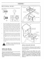
ASSEMBLY
HOW
TO ASSEMBLE
THE STEERING
WHEEL
Use the fasteners shown below to install
fasteners
are shown at full slze
the steering
B
15x88
Bottom
View
Make sure the front wheels
over the steering
on top
2
Push
The
©
A
1x10²
1
wheel
post
point
forward
Steeling
A
B
Top
View
Beaows
Slide the bellows
Make sure the collar
of the bellows
is
D 5699
on the top of the bellows
Attach
the steering
teners
as shown
wheel
Tighten
to the steering
post with the fas-
the fasteners
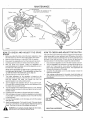
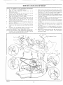
CHECK
HOW
TO ATTACH
THE HUB CAPS
Check
THE BELTS
the routing
of the belts
Make sure the belts
Push each hub cap onto the center
the washer
holds
Wheel
hub of each wheel
are inside
Make sure the belts are not twisted
all the belt guides
Make sure
the hub cap in place
i r,i
,,111
Motion Drive
Belt
Belt Guide
Guide
Mower
Drive
Belt Guide
Belt
Transaxle
Pul{ey
Pulley
Belt Guide"
CHECK
THE TIRES
Check the alr pressure
will
keep
in the tires
cause the unit to ride rough
the
pressure
mower
houslng
0-4825
Tires with too much air pressure
Also, the wrong
from
(PSI) for each Rear Wheel
cutting
level
air pressure
The
correct
is 14 PSI (10 kg/cm2)
will
air
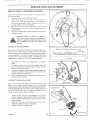
CHECK
and for
each Front Wheel the air pressure is 24 PSI (16 kg/cm2)
Models
that have seml-pneumet_c
front wheels will not have a PSI
THE DRIVE
The drive brake
brake
And Adjust
9
can be easily
BRAKE
checked
Move the shift lever to the neutral
If the rear wheels
F_92533
/
rotate,
The Ddve
adjust
Brake"
as follows
Set the parking
(N) posltlon_
the drive brake
Push the unit
See "How
To Check
ASSEMBLY
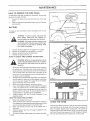
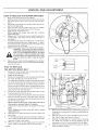
HOW
TO INSTALL
Use the fasteners shown
are shown full size
THE BAI-rERY
below
to install
the battery,
The fasteners
A
91565
B
Battery Tray
Drain Tube
Drain Tube
Clamp
A
Q
C
15x66
1
D
lx38
Check
the level of the acid
correct
2
level, add water
Attach
the
drain
tube
Fasten
the drain
tube
drain
tube through
drain tube along
If the acid has fallen
to the correct
to the
with
bottom
clamp
of the
battery
(A) as shown
the hole in the frame
the frame
below
the
level
tray
Push
as shown
the
Pull the
to the rear of the unit. Make sure
the drain tube is above the clutch idler spring
Fasten the
drain tube to the side of the frame with tie strap (S) as
shown
3
Set the battery
in the battery tray Make sure the battery
terminals
are towards the center of the frame The correct
position of the battery
Make sure there
terminals
are shown
are not any wires
under
in the illustration
the battery
O
Tie Strap
i
tray or
the battery
4
Fasten
sure
battery
5
the battery
there
Slide
battery
are net
with
the battery
any wires
clamp
between
as shown,
the battery
Make
C
and the
clamp.
the cover
cable
for the
positive
(+)
terminal
BLACK
onto the red
as shown
WARNING:
To prevent
cable to the
connect
the
terminal.
sparks,
positive
(+)
black
cable
fasten
terminal
to the
6
Fasten the red battery cable to the positive
the nut and bolt as shown
7
Slide
8
Fasten the black battery cable to the negative
with the nut and bolt as shown
9
To prevent
the cover over the positive
corToslon,
apply
the
red
before you
negative
(-}
(+) terminal
Covet
with
(+) terminal
grease to the battery
(-) terminal
terminals
0-4627.3
F-92533
10
ASSEMBLY
HOW
TO INSTALL
THE SEAT
Seat
Use the fasteners
shown
shown
below to instalt the seat The fasteners
D
are
at full size
Seal
(A)
lx45
(B)
18xlB
(C}
2x53
1
With
the seat hinge
towards
holes in the seat bracket
Pull the wire
bracket
with
2
harness
as shown
Align
the
the front
of the unit. align
with
the holes
between
the seat
sleeve
Do not damage
to the
seat
C
the
Seat
in the seat support
and the seat
to the seat support
Do not tighten
in the seat hinge
seat
Top
V_ew
the seat hinge
the protective
the holes
Fasten
(D)
tSx88
as shown
remove
from around
BoIlom
View
Fasten the seat bracket
the fasteners
Carefully
Bfackel
the fasteners
and the plastic
Wire
bag
the wire under the seat
to the holes
hinge
with
the
From
Switch
Seat
Sensor
in the seat
fasteners
as
Seat Bracket
shown
3
Check
the operating
be adjusted
adjusting
first
posltlon
of the seat
slide the seat forward
holes as shown
tighten
the
If the seat needs to
or backward
along the
To keep the seat bracket
rear nut
and
then
tighten
the
straight.
two
front
nuts
4
Sea_
Connect
the wire
harness
Make sure the tab part of the connector
seat switch
sensor
from
the seat switch
locks
into the latch
sensor
to the wire
from
of the wire
the
Holes
harness
/
connector
/
D #BO:
unit,
connect
the wire
from
the seat
WARNING:
For correct and safe operation
sensor to the wire harness
switch
of the
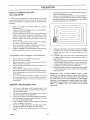
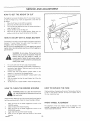
SPECIAL
MULCHER
The mower
lawn
CHECK THE LEVEL OF
THE MOWER HOUSING
The lever of cut was set at the factory
completely
read the Operation
After the unit is fully assemble.
mere
and look at the area that was cut If the mower
level, see the instructfons
F-92533
a short distance
housing
on "How To Level The Mower
does not cut
56212,
11
the
to
performance
blade
Housing"
There
of
difficult
accessory
Mow
that
the
lets you mulch
mower
housing
different
the
housing
cover
To operate
IMPORTANT:
Check
of the mower
cut
a grass bagger
Because
Section
has a special
fine
standard discharge unit or if used with
cotter must be removed
Make sure the level of cut is set at the height you llke for your lawn
the operation
housing
for a clean,
FEATURE
are
different
several
textures
cut., If you
of
the
is
Department
remove
mower
is not acceptable
with
of
a standard
blade
available
from
you
the
your
or
blade,
nearest
grass
grass
cover
grass
to replace
A standard
of
some
mulcher
discharge
need
the mu!eher
types
grass,
the
as a
is
and
bagger
the
mulcher
part
number
Sears
Service
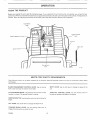
OPERATION
KNOW
Before
THE PRODUCT
you
operate
performance
accident
the
unit,
read this
instruction
When you read this instruction
followthe
operating
instructions
C]ulch,
book
book
compare
and the safety
If you understand
the illustrations
rules
Keep this
the unit and how
the unit operates
to the unit
Learn the location
instruction
book for future
you will
of the controls
get the best
To help prevent
an
reference
Bfake
Peda_
Throttle
Blade
Igrlilion
Control
Lever
Engag
SwiIch
ParMng Brake
Lever
MEETS
Sears Mowers
Commission
conform
to the safety
standards
BLADE ENGAGEMENT
CONTROL LEVER:
lever to start and stop the rotation of the blade
CLUTCH/BRAKE
function is a clutch
IGNITION
engine
LIFT
PARKING
engage
F-92533
of the American
Use the ignition
switch
Use the Hft lever to change
BRAKE
the brake when
LEVER:
Use
the
parking
increase
lever
to
you leave the unit
12
Institute
LEVER:
THROTTLE
The first
of cut
brake
Standards
SHIFT
unit
to start and stop the
the height
REQUIREMENTS
National
Use the control
PEDAL:
The pedal has two functions
The second function
is a brake
SWITCH:
LEVER:
CPSC SAFETY
and the US
Use the shift
CONTROL
or decrease
Consumer
lever to change
LEVER:
Use the
the speed of the engine
Product
Safety
the speed
of the
throttle
control
to
OPERATION
The operation
foreign
of any lawn
objects
result
in severe
glasses
mower
Wide
Vision
Retail
eye damage
Mask
safety
glasses,
Completely
2
Lift the parking
3
Remove
which
or Catalog
in
can
wear safety
lawn
the
J
Shift Gate
for over the spectacles
available
at Sears
J
Stores
MOWER
TO SET THE PARKING
1
can result
eyes,
Always
Safety
TO USE THE
HOW
mower
in the
or eye shields before starting
your
and while mowing
We recommend
or standard
HOW
thrown
BRAKE
push the clutch/brake
pedal forward
brake lever
foot
from
release the parking
will hold the unit
your
brake
the clutch/brake
To
parking
lever
pedal
and
then
Make sure the parking
brake
i
release
the
clutch/brake
pedal
automatically
release
brake,
forward
WARNING:
completely
The
Before
you
push
parking
leave
brake
the
the
Z _
will
operator's
position
Set the parking
brake
Move the blade
position,
move the shift lever to the neutral
(N)
engagement
control to the DISENGAGE
posffion
Stop
HOW
the engine
and
remove
the ignition
,-2
key
m
TO STOP THE UNIT
Tab
1
Push
the pedal completely
your foot
2
Move
forward
to stop
the unit
Keep
THROTTLE
on the pedal
the
blade
engagement
control
to the
DISENGAGE
position
3
Move
4
Set the parking
the shift
5
Move
6
To stop the engine
to the SLOW
turn the ignition
stopped,
Before
you
pedal
move
the
forward
the transaxle
Completely
unit
can
LEVER
shift
the throttle
pedal forward
Move
To move the shift lever to NEUTRAL
control
lever to the SLOW
and then
release
Then
Slowly
6
on the pedal
Move the throttle
comrol
7
To move the shift
lever to REVERSE
NOTE:
noise
F-92533
FAST
gear. pull
the lever goes
NEUTRAL
pull
Do not keep your foot
;o the FAST
position
position
stop the unit
Move the
First move the shift lever
until the shift lever stop clears the shift gate. and
back to REVERSE
Belt noise
is normal
gear from
the clutch, brake pedal
shift lever to the NEUTRAL
position
push the lever forward
5
to the right
then move
to stop the
from a forward
to the left until
To move the shift lever to a forward
the lever to theleh
push
If the unit is not
on the pedal
3
the shift lever back
past the tab
completely
be damaged
push the clutch,brake
Keep your foot
lever,
to stop the unit
2
4
position
key to the OFF position
the key
the clutch/brake
1
control
TO USE THE SHIFT
CAUTION:
position
brake
the throttie
Remove
HOW
lever to the NEUTRAL
can occur
when
and does not affect
the
the
clutch
is engaged.
operation
This
of the unit
I3
OPERATION
HOW
TO USE THE THROTTLE
Use the throttle
control
engine
1
To start
CHOKE
2
The
to increase
a cold
engine
or decrease
move
the
lever
the speed
to the
or
position
FAST
position
is marked
with
a detent
For normal
operations
and when using a grass bagger
the FAST position
For maximum charging
move the lever to
of the battery and
also
the engine
for a cooler
throttle
4
of the
START
running
engine,
operate
FAST position
For transport and to tow pull behind attachments
3
HOW TO OPERATE WITH
THE MOWER
HOUSING
CONTROL
The
control
engine
governor
performance
speed
HOW
to the needed
adjust
the
factory
governor
cutting
the
height
sidewalk
curing
height,
raise or lower
can be set from
1 V2 to 4 inches
lift
the
When
lever
the btade engagement
control
to the DISENGAGE
Use the biade engagement
control
is damaged+
replacement
ground
in the down
position
replace
it with
a
part
first and then lower
3
Move
position
4
Move
the
position
5
Push
the clutch/brake
6
Move
the shift
the throttle
Slowly
Move the throttle
release
go faster
9
Make
to start and stop the rotation
the
ENGAGE
forward
in heavy
lever
control
grass
or mow
in the slowest
with
a
speed
pedal
to the FAST position
If you need to
stop the unit and move the shiftiever
to
setting
sure the level of cut set at the factory
on "How
section
of
mow
shift
or slower
speed
to
pedal completely
the clutch/brake
After you mowa
contro_ Jn the illustration
control
lever to one of the speed settings
you
7
to the SLOW
engagement
put the
8
position
control
blade
When
bagger,
and move
in high or thick
grass cut the grass in the high position
the mower housing to a lower position
CONTROL
of the blade engagement
deflector
the
Do
forces
the engine
If the mower
See the location
toward
Move the lift lever to a height of cut position
another
HOW TO USE
THE BLADE ENGAGEMENT
material
keep the deflector
Start
The
you ride on a
or a road. move the lift lever to the HI position
discharged
1
maximum
HEIGHT
the
the
device
The deflector
2
NOTE:
To change
is a safety
in the
to increase
THE CUTTING
the deflector,
factory
of the engine
TO CHANGE
remove
If the
move the
for
"['he deflector
not
Always
speed
is set at the
Do not
WARNING:
short distance
housing
Iookat
does not cut level
To Level The Mower
is still correct
the area that was cut
see the instructions
Housing"
in the maintenance
the blade
1
Before you start the engine
the DISENGAGE
position
2
Move
the centre{
make sure the control
lever to the ENGAGE
leve+ is in
position
WARNING:
select a safe Forbettercontroloftheunit,
speed
to rotate
the blade
Note : If the engine stops when
the seat switch
is not activated
middle
of the seat
to the
3
Move
Also.
make
you engage
Make sure
sure the wire
the rotary
TO OPERATE
WARNING:
is connected
lever to the DISENGAGE
btade
control
Before
you leave
lever to the DISENGAGE
position
the operators
position
check
move
1
the unit.
the
follow
btade
quickly
parking
3
THE UNIT
the steps
engagement
to
the
DISENGAGE
5
Raise the lift lever to the HI position
3
Move the
and FAST
4
To go faster
F_92533
thrortle
move
centre+
the shift
to a position
between
lever to a faster
that
ride the
Guide" in the
on how to
SLOW
speed
14
a hill
move the shift
lever to the
speed settings
on a hill
If you must
pedal forward
and set the
blake
the
make sure the shift {ever is the slowest
throttle
control
to
the SLOW
speed
position
S{ow+y
have enough
space
the pedal
If you mast stopor
start
for the unit to roll when
the clutch
position
2
slopes
Never
See the "Slope
for information
push the clutch/brake
To start again
release
below
contro_
up
speed
Do not stop or change
stop
4
Move
straight
slopes
Before you ride up or down
slowest
Move
HOW TO TRANSPORT
ride up or down
to back
the
position
awayfromtheblade+deflectoropening
and the
WARNING:
Always
mower
housing
when keep
the your
engine hands
runs and feet
1
Do not
unit across a slope
back of this book
to stop
2
To transport
THE UNIT ON HILLS
are too steep
make sure the blade has stopped rotating
Before you ride the unit on a sidewalk
or a road
4
HOW
the blade(s)+
you sit in the
seat switch
the centre{
always
on a hilI
always
you release
the brake and engage
Be very careful
onastopeorina
when you change directions
on a hill When
turn onahill
move the throttle control to the
SLOW
to help prevent
position
an accident
OPERATION
BEFORE STARTING
THE
ENGINE
HOW TO START
THE ENGINE
WARNING:
CHECK OIL - Add as needed
operator
NOTE:
Do
not
check
the
level
of
the
oil
while
the
switch
engine
on the seat
1
Make sure the unit is tevel
2
Clean
Wipe
3
the
area around
the oil from
the dipstick
Remove
will
the
the dipstick
the dipstick
untiI it is tight
Remove
the dipstick
dipstick
oll
must
The
dipstick
If necessary,
4
add oil until
the dipstick
shown
level
the FULL
the oil reaches
The quantity
of oiI needed
on the dipstick
mark
on
NOTE:
the
position,
regular
is fresh and clean
and shorten
unleaded
from ADD to FULL is
oil
gasoline
Leaded gasoline
the life of the valves
I
Sit
Make
A mixture
of alcohol
unIeaded
(called
gasohol)_
deposits
during
storage
in the fuel
engine
fuel system
Start
before
carburetor
the
storage
moisture
the unit
with
of 30 days
the
After
storage,
instructions
Never
or carburetor
cleaner
damage
Drain
Move
5
Turn the ignition
sure
for additional
cleaner
Always
container,
use
Do not smoke
to the fuel tank,
are
inside
an
a
the
the fuel
7
adding
Do not add gasoline
enclosure
Before
you use
gasoline,
stop the engine
for several minutes
gasoline
gasoline
when
you
you
add
and let the engine
cool
CARBURETOR
The factory
settings
the engine
is operated
adjust the carburetor
in the maintenance
for the carburetor
under
mixture
are for most conditions
the following
conditions
See "How To Adjust
1
The engine
A change from summer to winter operation
A40 ° change in the operation
temperature
The engine
F-92533
If
can
The Carburetor"
section
2
3
was adjusted
you
has a loss of power
or does not run smooth
The carburetor
at 80 ° at the factory
is operated
above
4 000
the engine
to
depress
the
engagement
the
the
NEUTRAL
control
to
the
seat
Completely
pusl_
the
Keep your foot on the pedal
engagement
(N) position
control
to
the DISENGAGE
control
to the CHOKE
After
the
feet
15
position
key to the START position
Release the key
starts
If the engine
engine
CHOKE
to a needed
Before
you begin
minutes
position
information
safety
make
This system
you
lever
does
not start
control
after four
to the FAST
to start the engine
If the engine
TROUBLE
SHOOTING
CHART
in the fuel tank
when
unless
shift
blade
of
move the throttle
can occur,
WARNING:
the throttle
NOTE:
the fuel lines and
make
is sitting
always
correctly
lever to the NEUTRAL
blade
4
6
or longer
start
the
pedal forward
the shift
acid
empty
the
middle
Move
the acids
system,
run until
,flesh fuel, See the storage
use engine
and cause
is in storage,
the fuel
Let the engine
are empty,
or permanent
the
Move
and
fuel system
problems
the engine
attract
While
can damage
To prevent
will
or methanol)
protection,
position
will _ncrease deposits
(ethanol
components
if the operator
operates
not
move
move
3
sure the
Do not use premium
These
an
position
in
when
gasoline
tank,
and
2
gasoline
CAUTION:
system
For your
has
a sensor
the engine
when the operator
leaves
if the blade
engagement
control
is
will
pedal,
clutch/brake
fuel tank with
gasoline
engine
DISENGAGED
ADD GASOLINE
Fill the
The
clutch/brake
the FULL mark on
Do not add too much
stop
seat
system
that includes
engaged
Check the oil level on the
reach
electrical
system
in the seat
sure this system
Insert the dipstick into the oil fill tube Turn the dipstick clockwise
4
mounted
tell the electrical
runs
the
The
presence
starts
move
the
will
or five tries.
position
not
Again
start,
throttle
try
see the
control
from
speed
.work,
let a cold
engine
run for several
To start a hot engine move the throttle
between
FAST and SLOW
control
toa
OPERATION
HOW TO OPERATE
AS A MULCHER
A Mutcher
cuts
the
THE UNIT
Discharge
7
more
8
grass
fine
so that
the
grass
a
a
o
When
you mow
can be easily
driveways,
large areas, start
discharge
making
left turns
Operate
the
throttle
setting
engine
of
the
Riding
Mower
at
the
If the grass is wet, it will be difficult
cut and cause
of grass
clumps
must
not
second mowing
During the mowing
cause
be too
high
season
Set
the mower
when
housing
- ....
housing to the
of cut for the
the grass grows
the ends of the grass to become
Clean the underside
debris
quick_y,
..i
of the mower
can keep the mower
from
If the quality
working
Grass and other
9
correctly
If the grass is very high, cut two times to decrease
the engine
of cut is marginal, try the following:
I0
First cut with
and
cut.
For better
of cut at a higher
Cut the grass more
Operate
ground
speed
11
at a slower
FAST throttle
control position
Overlap the path of cut instead
Mow
height
frequently
the mower
mower
cutting
and
at the
of the
the shift
housing
across
13
the marginal
areas a second
time
Keep the blade sharpened
See "How To Sharpen The Blade 't
in the maintenance
section of the Owner's
Manual for the
Riding
took
mower housing
the maintenance
Riding
better,
check
the
cutting
level
more
See "How To Level The Mower Housing" in
section of the Owner's
Manual for the
blade
AND
BAGGING
TIPS
2
For the mower housing to cut level, make sure the tires have
the correct amount
of sir pressure {PSI)
3
Ever,/time
you use the unit, check the blade
bent or damaged,
immediately
replace
level of the
Housing" in
If the blade is
the blade
AIso_ make
sure the nut for the blade is tight
Keep the
blade(s)
sharpened
ends of the grass to turn
Do not
discharge
Use the
cut or bag grass
correctly.
teft
side of
Worn
blades
cause
the
brown
that
is wet
Wet
Let the grass dry before
the
will
mower
housing
grass
will
not
near
an
cutting
to trim
object
F-92533
and an even discharge
the engine
operate
and the shift
performance
with
of the
the throttle
the engine with
and a quality
speed
in
the throttle
lever in first or second
lever in one of the slower
the
gear.
cut, mow
with
gears
and top of the mower housing
performance
difficult
to
Also.
mower
housing
will
a fire
There
of the
with
is
Department_
For a lawn to look better, check the cutting
mower housing
See "How To Level The Mower
the maintenance
section
HIGH
for
a clean
5621 2,
I
housing
are
different
cut.
several
different
textures
If you
remove
of
types
grass,
the
of
some
mulcher
grass.
grass
plate
is
and
the performance
of the mower
discharge
or grass bagger
accessory
is not acceptable
you need to replace the mulcher
Mower
MOWING
mower
in the
for better
Because
of the
the load on
housing
After each use, clean the bottom
IMPORTANT:
to
operate
cutting
help prevent
Mower
For a lawn
the
performance
FAST position
When you use a bagger,
For better
the mower
lower
always
in FAST position
12
of using the full width
then
engine
cut grass,
Set the height
,'J
brown
housing
position
second
6
mow in the opposite
finished
to
you need to mow more than once a week
Keep a sharp edge on the blade_ A blade that is not sharp will
5
so
fences,
FULL
The grass must be dry
grass is too high. set the height of the mower
maximum
height
Then, lower the height
4
until
to the right
from shrubs,
etc After one or tame rounds,
direction
height of cut so that only the top third of the grass is cut. If the
a
by turning
away
below
The grass
o
area The result is a
of cut grass
that the cut grass will
recycled
Because the nutrients are returned to the soil, the lawn
will need less fertilizer'. To correctly
muJch the lawn, follow the
tips
the cut grass onto the mowed
even discharge
16
a standard
blade.
available
from
A standard
your
blade,
nearest
part
Sears
number
Service
OPERATION
HOW
TO CONVERT
The mower
housing
THE MOWER
has a speclat plate that lets you mulch the lawn
for a clean, fine cut The mulcher
the mower
housing
to freely
How to remove
ptug
prevent
accident.
Make
Fasten the
future use
bolts
IMPORTANT:
There
are
Because
of the different
as shown
D_4S33
the
mower
blade.
from
the
to the
plate
need
plate
or
grass
bagger
the
mulcher
to replace
A standard
your
blade,
nearest
part
Discharge Chute
and the
number
Sears
Service
Department°
How to assemble
the mulcher
plate+
Tabs
\
WARNING:
plug
to
prevent
accident,
Make
control
1
Remove
Disconnect
lever
the wing
the
the
engine
sure
is in the
the
wire
to
from
spark
starting
blade
Side Tab
\
by
engagement
DISENGAGE
nuts and carriage
the
position
bolts from
the mulcher
Carriage
plate
2
Lift the discharge
discharge
chute
Slide the
mulcher
plate
under
the
chute from the front to the rear Make sure the two
tabs on the plate
are to the front
of the nuts for the chute
bracket Also, make sure the side tab flts inside the discharge
opening, Push the plate to the rear so that the two tabs lock
around the nuts as shown
3+
Fasten the mulcher
nuts as shown
plate with
two
carriage
bolts
and wing
PUSH
0*4832
F+92533
Cover
for
muloher
discharge
you
available
nuts
Mulcher
different
types
of grass.
of grass,
some
grass is
to out. If you remove
a standard
is
bolts
and lift the plate away
and wing
several
textures
is not acceptable
with
position,
housing
carriage
of
by
engagement
DISENGAGE
plate to the front
spark
starting
blade
nots and carriage
the mower
56212,
the
to the
from
wlng
from
blade
sure
wire
the two
the mulcher
accessory
engine
is in the
Slide
performance
the
the
lever
Remove
difficult
plate,
control
1
to convert
or bag the cut grass
Disconnect
to
2
more
plate must be removed
discharge
the mulcher
WARNING:
3
HOUSING
17
Bolts
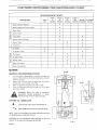
CUSTOMER
RESPONS BIUTIES
MAUNTENANCE
MAINTENANCE
PROCEDURE
R
I
Blade,
Inspect
Blade
Engagement
EVERY
25
HOURS
Control,
Clutch,
X
Check
Check
Check
EVERY
100
HOURS
BEFORE
STORAGE
& Charge
X
X
X
X
Ba_er T, Clean
X
X
Lubrication
x
x
x
Air Screen,
x
Check
X
X
Oil, Change
Air Filter,
Muff!er,
Spark
STORAGE
DATES
X
Check
X
Batter/,
EVERY
5O
HOURS
X
& Sharpen
Oi!, Check
G
I
CHART
Brake, Check
Tires,
R
FIRST
2
HOURS
EACH
USE
CHART
Clean
x
X
X
X
Check
x
P!ug, Check
Spark Plug,
x
x
x
RepIace
MOWER
GENERAL
RECOMMENDATIONS
1
owners
It is the
product
which
warranty
responsibility
extends
to correctly
maintain
the life of the product
coverage
2
Once a year you must check the spark
,ubrJc .... he unit, and clean the air filter
plug,
,_
rkC,,e
-_......
.he f_,_ne,=_*=
,_ _nd= make sure the'r
_re= tight
......
operating
4_n,en_nc_
TO
NOTE:
{except
Before
the wife
Apply
the areas
grease
with
If the unit is operated
dry graphite
,o ke_p your
brake
unit _n good
carburetor),
you make
an
from the spark
or repair,
inspection,
plug
LUBRICATE
Lubricate
_'_'w#;-
SecJon
drive
condition
adjustment
WARNING:
disconnect
WHERE
this
and to maintain
spray
to lubricate
shown
a brush
in dry areas
with
engine
oil
to the areas shown
that
O-€804
have sand. use a
the unit,
CAUTION:
Do not lubricate
the nylon
wheels
Oil or grease will damage
the
bearings
bearings
for the
front
O_-367_
F-92533
18
MAINTENANCE
iNSPECT
BLADE
WARN!NG:
Before you inspect
or remove
the
......
d_sc_nn_,
t ....
_._ ,o .... _..,
plug
the b!adeh .... nobj_ct,
stop the engine
Che&k
the un.t for damage
The blade has sharp edges
When you ho!d the blade, use g!oL, es or cloth
,t_o,,.
t_r
_
,4e
material
to protect
h.n_
l, TO,- ,,eer, ,h ......
e ..... _, _,,d ,n_. ......
b .......
d .... g_
e
........
_.,c ......
e, _nd
more safe to operate
Frequently check
check the-.,.,
_'h_H"
_, blade Keep the nut tight If,h_hlode
hits _n object. _,o_, ,he engine
.....
nnec, J ...... _+_ ,o ,he spark
_'"_"h'_See if the bLd_ _ be,,t o, d_m_d
_h_c. ,h .........
_,,_r
for damage
Before you operate .h .,_; . _1_
,4_,4
_
or.g,._, e,_,J,_...ent _.Jt See the authonzed service dealer
in your area Ever/three
years he,, _ _..h_ ;_._
_,;
_=._
inspect
the blade or replace
the o!d blade ;vith an origins!
equipment
part
HOW TO REMOVE
!
2
3
4
5
B
7
B
9
!0
RetooLs the
To Remove
Use a piece
Remove the
AND
INSTALL
B!_de
Adapter
B!_de
THE BLADE
mower housing
See the instructions
on "How
The Mower Housing"
of wood to keep the blade from rotating
nut that ho!ds the Made
Check the blade and the blade adapter
according
to the
instructions
for "inspect
B!ade" Replace a badly ,.*zorn or
damaged
blade with an origins! equipment
blade
See an
authorized
service dealer in your area
Cleanthetopandbottomofthemowerhous_ng
RemoveaN
the grass and debris
Mount the blade and blade adapter on the mandre! as shown
Mount the blade so that the hi-!ift edges ere up as shown
!f
the blade is upside down the blade wi!! not cut correctly and
can cause an accident
Fasten the blade with the odgina! washers and nut Make
sure the outside rim of the Be!!evN!e washer is against the
blade as shown
Tighten the nut that holds the blade to a torque of 30 foot
pounds (41 .SN-m)
Install
the mower
housing
See "How
To Install
The
Mower Housing"
the blade
WARNING:
accident
HOW TO SHARPEN
A loose
Always
D
_66]
nut or blade can cause an
keep the nut tlght that holds
THE BLADE
is not correctly
balanced
or if the blade
is
damaged,
A Vibration
blade that canis damaged
WARNING:
be caused with
if the cracks
blade
c_..
_- br_k
_
an__ c_,._e
_.._ _n
_ accident
Keep a sharp edge on the blade A blade that is not sharp wi!! cause
the tips of the grass to become brown
1
Sharpen the blade two times s year or e_:erl 25 hours
2
Remove the blade according
to the Mstructions
in "How To
Remove And Install The Blade"
3
Clean the blade with a brush, soap and water
Check the
blade
Look for cracks, nicks, or other damage
Replace s
badly worn or damaged
Made with an original equipment
blade See an authorized
service dealer in your area
4
Sharpen the blade with a file Make sure you keep the original
bevel angle.
5
Make sure the blade is balanced
Use a screwdriver
and hold
the blade parallel to the ground as shown
A blade that is
balanced will stay para!lel to the ground
If the blade is not
balanced, the heaw end wi!t rotate toward the ground Sha_en
the heavy end until the blade is balanced
6
A new blade will cut better than a badly worn blade Ever/
three years, have an authori=ed
seP41ce person inspect the
blade or replace the old blade with an original equipment
blade
7
Assemble
the blade according
to the instructions
"How To
Remove And Install The Blade"
F-92533
19
D-3509-1
Screwdriver
Blade
parallel
is balanced
when
to the ground
Ground
MAINTENANCE
HOW
TO CHECK
THE BLADE
AND
ENGAGEMENT
engagement
WARNING:
1
2
3
4
5
6
7
ADJUST
CONTROL
control
must anoperate
To
prevent
injury, correctly
the blade
Stop the engine
Disconnect
the wire from the spark plug.
Before you adjust the blade engagement
control lever check
and tevet the mower
housing
See "How
To Level The
Mower Housing"
Set the height of the mower housing in the lowest position
Move the blade engagement
control
to the DISENGAGE
position
Check the blade engagement
control lever Before the blade
engagement
control engages
there must be 1/8" to 3/8"
(3ram to 9ram) of free movement
If an adjustment
is needed
disconnect
the clevis from the
pivot rod and bracket assembl'r
Turn the clevis clockwise
to
Blade Engagemenl
Control
Lever
decrease
the free movement
of the blade engagement
control
Turn the clevis counterclockwise
to increase
the
free movement
Connect the clevis to the pivot rod and bracket assembly.
Move the blade engagement
control
to the DISENGAGE
position
Check
the
free
movement
of
the
blade
engagement
Position
D-4658
control
o
\
8
9
10
11
Check the operation
of the blade brake Rotate the pulley
with your hand Make sure that the blade brake pad presses
tightly against the pulley
Move
the blade engagement
control
to the ENGAGE
position
Check the blade brake pad tf the blade brake pad is
excessively
worn or damaged
replace the blade brake pad
assembly
Correct
replacement
paris and assistance
are
available from an authorized
service center
Connect the wire to the spark plug Mow for a short distance
and again check the operation
of the blade engagement
control
When
you move the blade engagement
control
to the
DISENGAGE
position
all movement
will stop within
five
seconds if the adjustment
is correct
If all movement
does
not stop
again
adjust
the blade
engagement
control
beginning with the first step If you need assistance
take the
unit to an authorized
service center,
12
If you replace
the mower
drive belt
adjust
the blade
engaqement
control lever
2G
F_92533
Pad Against
Pulley
With Blade Control
in DISENGAGE
Brake Pad
position
}
r_
"Away From Pulley
With Blade Control
I
| In ENGAGE position
,'1
i1.
p,
I
I
J
L.
I
J
I
I
I
e,5298
I
MAINTENANCE
/
Washer
_._
(To increase the operation of the
Adjustable Nut
brake, turn counterclockwise )
Brake Rod
/
Cotter
Pin
/"\
Washer
1/2" to 5/8
(13ram to 16turn)
Clearance
Pedal
Lever
/
Cotter Pin
Ctutch Rod
HOW TO CHECK
BRAKE
t
AND
ADJUST
THE
DRIVE
HOW TO CHECK
1
2
NOTE: If the adjustable nut will not line up with the hole in
the brake arm, go to step 6. If the adiustable nut does line
up with the hole in the broke arm, go to step 12
Pull the brake arm to the rear of the unit
6
7
3
4
The brake adjustment of the transaxle is located on the
underside of the transaxle on the left side Use one wrench to
hold the adjuster rod while you loosen the hex nut
approximately 2 turns with another wrench
Turn the adjuster rod clockwise 1/2-turn Try to push the unit
If the unit roils, continue this step until you feel resistance from
the brake when you push the unit
Turn the adjuster rod counterclockwise one turn Then, holdthe
adjuster rod with one wrench while you tighten the hex nut with
another wrench
8
9
10
11
Carefully push the brake arm forward and hold in position
With the brake arm forward, rotate the adjustable nut clockwise
on the brake rod until the adjustable nut is in line with the hole
in the brake arm
12
Connect the adjustable nut to the brake arm with
and cotter pin.
Apply the parking brake Try to push the unit If the
do not turn, the brake is correctly adjusted Release
brake Push the unit to see if the wheels will freely
13
,_
F-92533
THE CLUTCH
If the unit will not move when the clutch is engaged or if the belt slips
when going uphill or when pulling a load, the motion drive belt is
loose Check the clearance between the rear of the pedal lever and
the back of the hole as shown If there is more or less than the
clearance shown in the illustration, adjust the pedal as follows:
Before you adjust the broke, check the clutch adjustment See
the instructions on "How To Check And Adjust The Clutch "
Make sure the shift lever is in the NEUTRAL (N) position
Disconnect the adjustable nut from the brake arm as shown
Carefully push the brake arm forward and hold in position
With the brake arm forward, rotate the adjustable nut
counterclockwise on the brake rod until the adjustable nut is in
line with hoIe in the brake arm
2
3
4
5
AND ADJUST
Disconnect the adjustable nut from the idler bracket as shown
Turn the adjustable nut clock,vise to increase the length of the
clutch rod There must be 1/2-to-5i8-inch
clearance at the
back of the clutchJbrake pedal as shown This adjustment will
increase the clearance at the pedal
Assemble the adjustable nut to the idler bracket Check the
clearance at the pedal
After making an adjustment to the pedal, check the brake rod
as described in the instructions, "How To CheckAnd Adjust The
Drive Brake"
Adjuster_
Rod (Turn
Clockwise)
the washer
rear wheels
the parking
roll
VIEW FROM UNDERSIDE
take
the unitIf to
an cannot
Authorized
Service
Center.
WARNING:
you
correctly
adjust
the drive brake,
D-,4802
21
MAINTENANCE
HOW
TO REMOVE
To help service
panels
1
THE SIDE PANEL
and clean
can be easity
Remove
the
the engine
or the battery
the rear s_de
removed
large
screws
that
hold
the
front
of the
side
panel
2
Slide
the side panel
back approximately
one inch
Remove
the side panet
BATTERY
To charge
as follows
or clean
the battery
WARNING:
black
remove
To prevent
battery
terminal
sparks,
cable
before
WARNING:
which
the battery
from
The battery
disconnect
the
negative
(--)
the
you disconnect
is harmful
from the unit
the
contains
to the skin,
the acid gets on your
with water immediately
red cable
sulphuric
acid
eyes and clothing.
body
or clothing,
If
wash
BLACK
1
Remove
the black cable
2
Remove
the red cable from
3
Remove
the battery
clamp
4
Remove
the battery
from
HOW
TO
CHECK
AND
the negative
the positive
from
(+) terminal
the battery
When
THE
BATTERY
you charge
Keep the battery
The fumes
/
(+) terminal
the unit
CHARGE
WARNING:
smoke,
from
from
the
the battery,
away
battery
from
acid
do not
any sparks+
can cause
an
explosion.
1
The battery
witl be damaged
the
level
correct
Check
if the battery
the
battery acid must touch the bottom
acid has fallen below
the correct
correct
level
the result
2
Do not add battery
wilt
the engine
not
stay
fully
charged
3
4
Use a 12 volt battery
the battery
you charge
charged
TO
Wash
acid
falls
or
charger
of the battery
the battery
to charge
Do not
llfe
Install
e+4627-3
the battery
CUT AWAY VIEW
months
remove
the battery
for 2 to 3 hours
add water
If you frequently
After
acid
the
Charge
at
battery
is
]f the level of the
add battery
acid
to a
in the
CLEAN
THE
the battery
the battery
BATTERY
from
with
the unit
a sotution
of baking
of one gallon
soda (sodium
of water
bicarbonate)
CHECK THE TIRES
and
Make
sure the solution does not get _nto the battery cells
Clean the terminals
and the ends of the cables with
wire
Bar_ery Clarn_
section
four tabtespoons
4
The
battery
charged battery or the result can be an explosion
Install the battery
See "How To Install The Battery"
Remove
3
For longer
check the level of the battery
assembly
HOW
system
use the headlight,
every three
the battery,
a rate of 3 amperes
5
acid to a charged
charging
or frequently
charge
Before
battery
acid
of the vent If the battery
level add water to the
can be an explosion
The engine has a 3 amperes
start
acld is not kept at
level of the battery
Check
a
brush
keep
the battery
assembly
5
To prevent
F-92533
section
corrosion
See "How
To Install
The Battery"
the air pressure
in the
the
pressure
mower
grease to the battery
terminals
that
22
housing
Tires with
Also,
from
the air pressure
have semi-pneumatic
front
too much air pressure
the wrong
cutting
(PSI) for each Rear Wheel
each Front Wheet
apply
in the tires
will cause the unit to ride rough
level
air pressure
The
correct
is 14 PSI (10 kg/cm2)
is 24 PSI (16 kg/cm2)
wheels
will
will
air
and fol
Models
not have a PSI
MAINTENANCE
ENGINE
HOW
TO CHECK
NOTE:
Do
not
check
Air Street:
THE OIL
the
level
of
Dipstick
the
oil
while
the
engine
runs,
1
Make sure the unit is level
2
Clean the area around the dipstick
Wipe the oil from the dipstick
3
Insert the dipstick
wise
until
4
The oi! level must
on
the FULL mark
on
the oil reaches
Do not drain
get
oil on the
Remove
clean
Before
minutes
Drain
and tighten
the oil completely
the oil drain
Nothing
you change
tile
Clean
range
before
the
Oil Drain
the
be added
oil change
Oil must
The engine
be a
engine
SAE viscosity
15!3ojj3
3i
II11-To protect
when
the temperature
32 ° 40 =
60 °
the starting
system,
4
Clean
Slowly
the
is lees than
area around
the oil extension
5
Insert
the
80 °
100 °
dipstick
in a clockwise
dipstick
Check
F-92533
use SAE 5W30
oil
°F
32 ounces
Remove
the dipstick
(0 9 liters)
of oil into
tube
dipstick
reach
32
the dipstick
pour approximately
into
the
direction
oil
extension
tube
until it is tight
the ell level on the dipstick
the FULL mark
enters
on this
unit
through
SYSTEM
is air cooled
the
The air
air screen
that
on top of the
1
Remove any grass
cloth or brush
2
Inspect
the edge
Remove
any grass or debris visible
engine
C_4682,1
CAUTION:
of shroud
cools
the
engine
grades
-1 I I
0_
edge
Cap
HOW TO CLEAN
THE ENGINE COOLING
chart below
oil
Required
and debris
oil helps to
to theoil
of the oil to use
next
grass
bottom
cap
use the temperature
grade
from
Detergent
must
the oil
viscosity
SD. SE or SF grade
-20 °
you drain
Makesureyoudo
from
SEorSFdetergentgradeoii
to select
Temperature
THE OIL
run for several
the engine
Before
ell
belts
Install
UseaSD
ADD to FULL is
Do not add too much
the oil drain cap
engine
from
the oil fromacoidengine
the oil, let the engine
3
the FULL mark
of oil needed
TO CHANGE
c!ock-
the oil level
teach
add oil until
NOTE:
2
Check
The quantity
on the dipstick
the dipstick
Turn the dipstick
the dipstick
the dipstick
HOW
1
Remove
If necessary
shown
not
into the ell fill tube
it is tight
on the dipstick
the dipstick
Remove
Turn
the
Remove
the
The oil tevet must
on the dipstick
23
shroud
dirt or debris
of the engine
from
shroud
the air screen
with
a
for grass or debris
at the bottom
edge of the
MAINTENANCE
HOW
TO CLEAN
THE AIR FILTERS
@"_'-"-'-"_Wingnut
Some engines
paper
dirty
filter
Never
will
an outer
Clean the air filters
conditions
NOTE:
filters
have two filters,
service
more
run the engine
help protect
replacement
filter,
every 50 hours
If you operate
with
the air filters
parts
against
list
removed
wear
for the
Remove
Remove
the two wingnuts
from the cover
the cover from the air cleaner
3
Remove
the two
4
Remove
the filters
5
Clean the inside
6
Remove
nuts from
The air
For the correct
the filters
of the base and the cover with
foam
Cover
in
engine.
1
2
the
an inner
often
the engine
see the
foaro filter around
filter
(if equipped
Foam
a cloth
). from
the
Fih
paper
filter
7
If equipped
wash
the foam
filter
in a detergent
solution
To remove the water solution
filter in a dry cloth Remove the foam
Completely
dry the foam
filter
CAUTION:
Do not wash
solvents
that will burn
the
filters
and water
tightly roll the foam
filter from the cloth
in gasoline
or other
D :;_8
8
Evenly applySAE
9
To clean the paper filter
hard flat surface
10
11
If the paper filter is very dirty replace the filter
Assemble
the air filters with the two nuts
12
install
HOW
the cover
THE
filter
tap the paper filter
the cover
every 50 hours
mounted and is not
with a new muffler
to the dry foam
tightly
Fasten
TO CHECK
Check the muffler
damage
30Woil
with
againsta
the twowingnuts
MUFFLER
Make sure the muffler
is correctly
loose If the muffler is wotn or burnt replace
Aworn
muffler isa fire hazard and also can
the engine
If you mount
s spark arrestor
to the muffler,
also check
the spark
arrestor when you check the muffler
If the spark arrestor is worn or
damaged
replace it with a new spark arrestor
See your nearest
authorized
HOW
service
dealer
TO CHECK
for' a spark arrestor
THE SPARK
PLUG
\
1
2
Check
the gap of the
correct
gap is 0 030"
For easy starting
plug every two
spark plug
and good
with
performance
a feeler
replace
gauge
The
the spark
/!
years
)-429S
F-92533
24
/Check
an d Se[
Spar
k Plug'G_ap
\
SERVnCE AND
HOW
TO ADJUST
The factory
settings
the engine
is operated
adjust
Tbe engine
2
A change
3
A40
from
The engine
summer
2
With
in the operation
is needed,
your
side
hand
until
The carburetor
follow
4 000
feet
the steps
See
"How
below
To Remove
turn the idle mixture
screw
you feel some resistance
direction
main
Turn
the idle mixture
jet
screw
Turn
the main
4
Start
the engine
5
Move
the throttle
6
Turn the idle mixture
screw
the idle
to loose speed
the main jet
mixture
will
1-5/8
for several
turns
1I
minutes
until the engine begins
Slowly
turn the
idle mixture
the engine runs rough
mixture screw
of the slot in the idle mix-
-8
Set the
9
10
idle
mixture
steps
6 and 7
Move
the throttle
Turn
the
engine
screw
control
main jet screw
to
loose
until
between
the
two
positions
to FAST
speed
(lean
direction
mixture)
until
the
Note
the
is set too
1 16 turn
carburetor
clockwise
best
engine
pedormance
the throttle
control
set
the
Again
mixture)
direc_
Note
lean
Turn
the two posbions
operate
the blade(s)
If the engine
blade(s)
THE THROTTLE
the adjustment
stops when
15
(rich
the engine
are engaged,
the
runs rough
when
check
the engine
If necessary
the blade(s)
steps
mixture
counterclockwise
are engaged
centre!
and disengaging
13 or 14
as
s!o: on Le.ed
1
Move
3
Loosen
the
control
can move
cable clamp
from
3
from
the engine
4
up) with
Tighten
SLOW
screw
the centre!
the cable
clamp
bracket
remove
or disconnect
the
the cable
control
tever until the slot in the is a!igned
the hole in the control
screw
and then
Move
bracket
the throttle
back to the FAST
I
for the thrott}e
Oo not
lever
the clamp
position
so that
in the cebIe
position
control
Move the engine
(lines
"_
throttle
3400+
position,
Cab!e
control
position
IMPORTANT:
governor
Check
\
Center.
They
Control
speed is 2 ! 50 ± ! 00 RPM
Do not change
needs an adjustment,
have
the
the engine
governor
If the engine
go to the nearest
Sears Service
equipment
and
experience
to
make
adjustment
F-92533
Con:tel
C!amp
to the
control is at the FAST position,
the engine speed is
!00 RPM When the throttle control is in the SLOW
the engine
Thrott!e
as shown
the alignment
of the control lever See step 3
The thrott!e control is now set at the correct speed When the
5
the
c!amp
to the FAST
25
Bracket
the
Turn the main jet screw
by engaging
repeat
If the engine
the carburetor
main jet screw
mixture
is set too rich
1/16 turn
in steps 10
CONTROL
throttle
the
of the slot in the main jet screw
To check
in
in a counterclockwise
rough
13
position
in a clockwise
runs
Set the main jet screw between
and 11
of the slot in the idle
of the slot in the main jet screw
HOW TO ADJUST
For the
follows
counterclockwise
the engine
12
14
begins
position
screw
Note the position
turn the main jet screw
until
position
ture screw
7
Slowly
tion
position
screw clockwise
Note the position
Jet Screw
or
1_1/4 turns
counterclockwise
to SLOW
screw
be damaged
counterclockwise
Run the engine
control
Screw
in a clockwise
Turn
The carburetor
jet screw
Idle Mixture
Tl_e Side
until you feel some resistance
Do not over tighten
the
3
operation
temperature
above
panet
screw in a clockwise
CAUTION:
if
you can
at 80 ° at the factory
the
direction
conditions
conditions
or does not run smooth
to winter
is operated
If an adjustment
Remove
Panels"
are for most
the following
mixture
° change
1
under
has a loss of power
was adjusted
4
THE CARBURETOR
for the carburetor
the carburetor
I
ADJUSTMENT
Clamp
Screw
Cable
the
r
SERVICE
HOW
TO REMOVE
THE MOWER
2
Move
2
Move
the
DISENGAGE
3
Disconnect
the blade drive link
bracket assembly
See illustration
4
Remove [he hair pins thai hold time hangers Io the adius[er
plates See illustrabons
A'and'B
below
Move [he mower
housing
to the left until the right side
blade
engagement
position
ADJUSTMENT
HOUSING
1
5
_he lift lever to the MIDDLE
AND
position
control
lever
from the pivol
C below
[o
the
rod and
3
4
hanger sepa[ates
from the adjuster plate Then move [he
mower
housing
to the right ungt the left side hanger
separates from the adjuster plate
Remove the long pin from the front suspension
bracket See
illustration
'D" below
6
7
Remove the mower drive belt from the s[ack pulley Slide the
mower
drive belt beIween
_he stack pulley and the belt
guide
7
8
Comple:e[y
Iurn the steering
wheel
to the bghi
Pull the
mower housing away from the left side of the unit
6
HOW
1
TO INSTALL
THE MOWER
5
Push
Attach the rear hangers [othe adiuster plates Fasten with
the hair pins See illustrations"A"
and"B"
below
Connect
the blade drive link to the pivot rod and bracket
assembly Fasten with a clevis pin and a hair pin See illustration
C
below
Move the blade engagement
control lever to the ENGAGE
posibon
Make sure the mower drive belt is inside all the
be_t guides
Check the operation
of the blade engagement
control lever
See the instructions
Conlrol Lever
8
HOUSING
Completely
turn the steering wheel Io [he right
mower housing under time left side of the unit
Slide the mower drive belt belween
the stack pulley and the
beltguide
PuIthemowerdrivebellaroundthestackpulley
Make surethe"V
side of the mower drive belt is against the
stack pulley
Make sure the drive belt is not twisted
AItach the mower housing to the front suspension
bracket
with the long pin Fasten with the washer and hair pin See
illustration
"D" below
[he
on
How To Adiust The Blade Engagement
Make sure the mower housing islevel
How
To Level The Morner Housing
sectEon of this book
See_he;nstructions
in the maintenance
lade Enqagemen[ Con rol
Long
2 =iS=
F-92533
Blade
:
26
Pm
\
Drive
Link
SERVICE
HOW TO REPLACE THE MOWER
1
2
AND
DRIVE BELT
Move the lift lever into the low cut position
Slide the mower drive belt between the stack pulley
and the
5
belt guide
Remove the mower
drive belt from the stack
pulley
Pull the belt guide away from theidler
pulley
Remove the
belt from the idler pulley
While you push the belt guides away from the mandrel
pulley, remove the mower drive belt from the pulley
Install the new mower drive belt
6
NOTE:
Replace
the mower
drive belt with
a factory
replacement
belt
Make sure the "V" side of the mower drive belt is against the
3
4
mandrel
pulley
not twisted
Also
make
sure
the
ADJUSTMENT
mower
drive
belt
is
7
Pull the belt guide away from the idler pulle / Put the mower
drive belt around the idler pulley Make sure the "V" side of
the mower drive belt is against the pulley Also make sure the
mower drive belt is not twisted
8
Make sure the mower
WARNING:
drive belt is inside all the belt guides
If the mower drive belt is outside of
a belt guide
when
the blade
engagement
control
can continue
to rotate and damage
the mower
lever
is in Before
the DISENGAGE
the blade
drive belt.
you operate position,
the mower,
make
sure the mower
drive belt is inside all the belt
9
guides,
you mow.
Before
tdter
check
the blade engagement
See the instructions
on "How
ment Control Lever"
Remove
the mower
To Remove
lever
The Blade Engage-
BELT
housing
The Mower
D-5279
See the instructions
on "How
Housing"
2
3
Engage the parking brake
Disconnect the adiustebte
nut from the brake rod at the brake
4
Try to push each belt guide away from the drlve putley so that
arm
Push the brake
the motion
pulley
drive belt can be pulled
enough
to hold the head of the belt guide on top of
the frame
you use another
6
belt toward
Loosen
wrench
belt between
belt from
NOTE:
idler
7
the front
the top pulley
the stack pulley
the lower
Inspect
spring
to loosen
the nut
Puff the
Remove
the motion
of the stack pulley
and the belt guide
Slide the
Remove
the
pulley
the idler
for
Pulle
of the unit
the bett gulde at the stack pu!ley
drive belt from
Stack
clearance
use one wrench
drive
Pulley
over the top of the drive
do not provide
under the frame for each belt guide
Remove the motion drive belt from the idler pulley
5
Idler
rod to the side of the unit
If the bett guides
while
Pylley
'V" side
of Belt
HOW TO REPLACE
THE MOTION
DRIVE
1
To Adjust
control
damage
Install the new motion
pulley,
stack
Replace
pulley
and the drive
if necessary
drive belt on the top pulley of the stack
Drive Putle
D'4367~_
pulley
NOTE:
Replace
the
replacement
belt,
8
motion
drive
Make sure the "V" side of the motlon
belt
with
a factory
drive belt is against
1
the
stack pulley
9
12
Put the motion
drive belt around
the idler pulley
Make sure
the'V"
side of the belt faces away from the idler pulley
make sure the belt is not twisted
10
While
pulley
F-92533
you
push
install
the two
the motion
belt
guides
away
from
Make sure the motion
drive belt is inside the belt guides
the guide arm of the idler pulley
stack pu!ley
Also
13
See "How
To Check
Assemble
the adjustable
nut to the brake
sure the
is correctly
Make
instructions
drive bett on the drive pulley
14
27
And Adiust
brake
the mower
Install
The Mower
housing
Housing"
of the clutch
The Clutch"
on "How TO Check And Adjust
Install
and
the belt guide for the
Before you use the unit, check the adjustment
arm
the drive
Tighten
rod at the brake
adjusted
See the
The Drive Brake"
See the instructions
on "How
To
SERVICE
HOW TO LEVEL THE MOWER
if the mower housing
iawn will look better
is level, the mower
will cut easier
1
Make sure the unit is on a hard level surface
Check
[he
air pressure
tile
mower
in the tires
housing
the rear tires are inflated
3
If the
to !4 psi(lO
Move
for the
position
blade
the front
control
to the
Move the lever for the height of cut to the
middle position
There are two adjustment
the blade
engagement
is
Make sure
kg/cm2)and
to 24 psi (16 kg/crn2)
the lever
and the
air pressure
not cut level
tires are inflated
ENGAGE
4
will
ADJUSTMENT
HOUSING
2
incorrect
AND
procedures
below
that will
level
housing
WARNING:
Before
adjustment,
ot repair
wire
to the
wire to
accident
you
spark
plug
prevent
make
an
to the unit,
the
the
the spark
plug
Remove
engine
inspection,
disconnect
from
starting
D
by
THE SIDE TO SIDE ADJUSTMENT
Use a ruler
bottom
and measure
of
the
the distance
mower
housing
by the small round dimples
In correct
adjustment
be within
!/4"
1
the mower
housing
(6 mm)
of the same height
than
one
1/4" (6 ram}
or both
from
the
at points
of the hangers
C and O
f
in the
t
as follows
from
Measure From The Bottom Of Thc Mower Housing
J
C and D must
If the difference
adjust
/
to the
locations
{or X marks) at points
is more
Disconnect
the level surface
Measure
indicated
measurement
from
the
y
Level Surface
adjuster
plates
2
The higher
numbers
raise the height
will
3
lower
the mower
Connect
will
the hangers
level
the
adjuster
4
on the side of the adjuster
of the mower
housing
housing
into the hole of the adjuster
mower
ptates with
TO BACK
housing
Fasten
the
pIates that
hangers
the distance
houslng
indicated
adjustment,
will be 1/8"
mower
mower
to 3/8"
housing
Loosen
the front
(3ram
at point
the
jam
from
the
lower
housing
than
to the
locations
(or X marks) at points
to 9 mm)
from
the IeveI surface
of the mower
B Adjust
nut
from
Measure
by the small round dimples
In correct
housing
ADJUSTMENT
bottom
the
to the
the hair pins
Use a ruler and measure
of
will
numbers
Check the measurements
at each side of the mower
See the above instructions
THE FRONT
1
plates
The lower
A and B
at point
Suspension
A
Rod
the back of the
as follows
the
suspension
rod
Turn
the
Iocknut clockwise
to raise the front of the mower housing
Turn the locknut counterclockwise
to lower the front of the
2
mower
Check
housing
the front
adjustment
3
Connect
and
Tighten
the wire
rear
measurements
for the
correct
the jam nut as shown
to the spark pIug
Jam
F-92533
28
Nut
SERVICE
HOW
TO SET THE
The height
or raise
HEIGHT
of cut is sat at the factory
the height
of cut
make
AND
ADJUSTMENT
OF CUT
from
1'/_ to 4inches
an adjustment
To lower
to the
lifter
rod
Hair
Pin
as follows
1
2
Move the lift lever to the LOW cut position
Disconnect
the lifter rod from the lifter arm
3
Turn the lifter rod clockwise
4
raise the height of cut
Attach the lifter rod to the lifter
5
Move
the
pulleys
HOW
lift
lever
to lower
to the
or belt do not
TO START
position
the bottom
WITH
If "Jumper
emergency
NOTE:
The unit
system
Also,
ground
system
is equipped
acid
battery
away
prevent
sparks,
the
positive
black
smoke
can cause
from
negative
flames
the
terminal
or
Put a wet
Connect each end of the RED'Jumper
Connect
one
BLACK
4
negative
Connect
(--) terminal
of the charged battery
the other end of the BLACK "Jumper
of
the
sure you do not touch
",Jumper
Cable"
to
Cable"
(+)
the
the
to the
that has the weak
battery
last
Allow
the
to run
the "Jumper
TO CLEAN
Cables"
reverse
THE MOWER
the above steps
HOW
HOUSING
Grass and other
belt from
debris
working
Move
the
ENGAGE
on top of the mower
correctly
lever
Clean the mower
for the
blade
engagement
the
DISENGAGE
lever
for
engagement
housing
F-92533
control
FRONT
to the
start Thelocationofthe
fuse and replace
fuse
with a
control
of
WHEEL
ALIGNMENT
The alignment
of the front wheels cannot
be adjusted
If the
steering
is damaged
and the alignment
has changed
see your
nearest Sears Service Center
to the
position
Again clean the top of the mower housing
After you cut the grass, clean the bottom
the
as follows
housing
the blade
THE FUSE
can keep the
housing
position
Clean the top of the mower
Move
housing
TO REPLACE
If the fuse is blown the enginewitlnot
is next to the battery
Remove
15 amp Automotive
fuse
ing, stop the engine and disconnect
the wire to
WARNING:
Before you clean the mower
housthe spark plug
_
4
5
end
the engine
To disconnect
2
3
to
the
block
engine
1
To
cable
Cable" to the positive
3
HOW
the
sparks
over the vent caps of each battery
Make
6
the
connecting
terminais
of each battery
chassis with the cables
Start
from
Keep
red jumper
before
to
cable
1
5
to ground
The fumes
any
2
engine
in an
negative
an explosion
fasten
(+)
jumper
cloth
a 12 volt
must have a 12 volt
Do not
battery
the engine
below
with
vehicle
WARNING:
the
BATTERY
are used to start
procedure
the other
sure
thebatteryneedstobe
Cables"
folfowthe
Make
of the frame
A WEAK
Ifthebatteryistooweaktostarttheengine
charged
to
arm
HIGH
touch
or counterclockwise
the mower
29
STORAGE
At the end of each year, prepare
the unit for storage
(Over
30 Days)
as foilo',,_s
MOWER
CLEAN THE UNIT
t
Clean the mower
housing
See "How
To Clean The Mower
Housing"
LUBRICATE
THE
UNIT
See the "Lubrication"
instructions
in this book
ENGINE
1
Clean the dirt and grass from
2
Change
Oi!"
3
the oil
Check
the engine
See theinstrucdons
,,he air screen
"How
To Change
See the instructions
"How
The
To Clean
The Air Screen"
4
Check the spark p!ug
See "How To Check The Spark Plug"
THEFUELSYSTEM
building
or near a fire
Do not smoke
or the
WARNING:
fumes
from the
Do not
fuel drain
can cause
the gasoline
an explosion
inside
a
CAUTION:
During
from
occurlng
filter,
fuel
{called
hose
or using
it is important
system
and the
gasehol
causing
storage,
storage,
in fuel
fuel
parts
tank
ethanol
like
to prevent
the
Alcohol
deposits
carburetor,
fue!
gasoline
mixtures
attract
moisture
or methanol}
acid deposits
during
storage.
While
the unit is in
the acids in the fuel can damage
the fuel system
To
prevent
engine
problems
system
before
storage
!
Start
2
Run the engine
with
the fuel system,
empty
the fuel
of 30 days or longer
the engine
until the fue! tank and the carburetor
are out
Jel Screw
offue! and the engine stops Do not leave fuel in the fueltank
or the carburetor
The rue! can damage the function of the
e-4815
fuel system
3
After
storage,
make sure yco use fresh
fuel
BA]_ERY
!
2
Remove the ba_e_y
Clean the better'/ termina!s
of any deposits
See "How
To
Clean The BatteH"
3
CompIetety
charge the ba,rten/ See the instructions,
To Check And Chalge The Batter/"
4
Store
NOTE:
After
be charged.
F-92533
the baker'/in
a long period
a cool
"How
dr4 place
of time
in storage,
the
battery
must
30
TROUBLE
SHOOTING
(Recoii-Sta_
PROBLEM:
1
Follow
2
Clean
3
Check
wiring
4
Drain
filter
5
6
7
3
4
5
The engine will not start
the steps How To Start The Engine in this book
the battery terminals
Tighten the cables
for a loose wire Tighten the limit switches
(See the
diagram )
the fuel tank Clean the fuel Iine Replace the fue!
will
not turn
PROBLEM:
The engine
does
power
1
Check the oil
2
Clean the air filter
3
Clean the air screen
run smooth
The engine
does
1
2
3
Replace the spark plug
Adjust the throttte control
Clean the air filter
4
Replace
The engine
stops
seat
or has a loss
4
5
Adjust the carburetor
Check for a damaged
damaged
parts
run smooth
the
gear
PROBLEM:
The engine
1
Replace the spark
2
Clean the air filter
3
4
5
when
pulley
Replace
the
for the blade idler
unit
at fast speed
installed
the
belt
is
drive belt
will
not
move
drive belt
drive
be_t
when
Make
the
sure
ciutch
the
is
belt
is
correctly
The
unit
moves
slower
or stops
when
the
clutch
drive belt
the
always
sensor
sit
in the middle
PROBLEM:
When
can be heard
of
or a loose connection
always
across
a slope
sit in the
middle
1
the
fuel line
Replace
the fuel
3 1
the clutch/brake
pedal
is released,
belt noise
Temporary
belt noise does not change the operation
of the
unit If belt noise is continuous
check the routing of the belt
Make sure the belt is inside all belt guides
If the noise is continuous
adjust the clutch
PROBLEM:
of
will not idle
plug
Adjust the carburetor
Adjust the throttle control
Drain the fuel tank Clean
filter
F-g2533
The
engaged
1
Adjust the clutch
2
Replace the motion
3
Check the motion
1
seat
correctly
the mower
is engaged
1
Replace the motion
2
Adiust the dutch
On slopes, the engine stops
up and down slopes Never mow
To activate
the seat
the spring
installed
Replace
PROBLEM:
sensor
beIt or damaged
PROBLEM:
The mower
blades will not rotate
1
Check
the mower
drive
belt
Make
sure
of
2
2
Replace
PROBLEM:
Use a lower
Check the wiring harness for damage
Repair the damaged
wire
PROBLEM:
1
Mow
vibration
Replace the blade
Check for loose engine bolts
Check the air pressure in the tires
6
the fuel filter
blades are engaged
1
To activate
the
the seat
2
not
Excessive
1
2
3
2
Replace the spark plug
The engine is working
to hard
Adjust the carburetor
Replace the fuel filter
PROBLEM:
Adjust the carburetor
Replace the fuel filter
PROBLEM:
The mower
housing does not cut level
1
Check the air pressure in the tires
2
Adjust the level of the mower housing
3
Check the front axle If the front axle doesnol
freely pivot
loosen the two axte bolts
to start
PROBLEM:
in power
PROBLEM:
The grass does not discharge
correctly
1
Stop the engine Clean the mower housing
2
Raise the height of cut
3
Replace or sharpen the blade(s)
4
Move the shift lever to a slower speed
5
Move the throtde control to the FAST position
Repair the damaged
wire
Electric-Start
Models: replace the solenoid
Recoil-Start
Models: replace the module
not
a decrease
over
FoIlow the steps How To Start The Engine in this book
Check the level of the acid in the battery
If needed, add
water
Charge the battery
Replace the fuse
Check the wiring harness for damage or a loose connection
PROBLEM:
The engine is difficult
1
Adjust the carburetor
2
Replace the spark plug
3
Replace the fuel filter
4
5
6
7
3
4
PROBLEM:
The engine
CHART
Models)
PROBLEM:
A hot engine causes
1
Ctean the air screen
2
Check the oil
Remove the spark plug(s)
Move the throttle
to the SLOW
position
Turn the ignition key to the ON position
Try to start
the engine several times Install the spark plug
Replace the spark plug
Adjust the carburetor
PROBLEM:
1
2
And Electric
The
rear wheels
spin
over
Check the front axle tf the front
loosen the two axle bolts
uneven
terraln
axle does not freely
pivot
®
10 HPo ELECTRIC START
30" MOWER / MULCHER
5 SPEED
REAR ENGINE
Medea No,
The Model Number for the mower is found under the seat on a decal attached to the
seat support. The Model Number for the engine is found on the blowel housing above
the spark plug Always give the Model Number when you call for service or order repair
parts for your' unit
502.255020
Repair parts can be ordered
Sears Stores,.
from any Sears Service
Center/Departments
and most
WHEN ORDERING REPAIR PARTS, ALWAYS HAVE THE FOLLOWING iNFORMATiON
AS SHOWN IN THIS LIST
o
D
"
e
o
PRODUCT- REAR ENGINE RIDER
MODEL NUMBER- 502 255020
ENGINE MODEL NO_ - 14&426072
PART NUMBER
PART DESCRIPTION
How to Order
Repair
Parts
Your Seat's merchandise has added value when you consider Sears has service units
nationwide staffed with Sears trained technicians, Seats technicians have the
necessary parts, tools, and equipment to meet the Sears pledge, "We Service What
We Sell"
, ,ui
F-92533
11-22-91
Sears,
Roebuck
and Co., Chicago,
IL, 60684
U.S.A.
,L
Printed in US.&