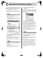
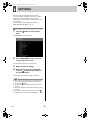
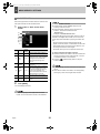
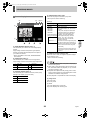
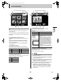
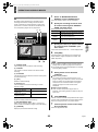
1
e00_l8hbe_xe_nw_7.book Page 1 Monday, April 26, 2004 10:40 AM e00_l8hbe_xe_nw_7.book Page 1 Monday, April 26, 2004 10:40 AM CONTENTS NETWORK CONTROL Controlling from a PC ..................................... 5 Controlling from the unit ................................. 7 Messages displayed when connected ........... 7 1 NETWORK CONTROL FUNCTION .............. 2 Operations possible with PC control .............. 2 Network settings ............................................ 2 3 OPERATION PANEL FUNCTIONS AND RESTRICTIONS.................................... 8 2 PREPARING FOR NETWORK CONTROL ... 5 NETWORK SETTINGS 7. PROGRAM REC SET ............................... 16 8. TIMER SET ............................................... 17 9. ALARM REC MODE SET ......................... 18 10. DISPLAY SET ......................................... 20 11. BUZZER SET ......................................... 21 12. HDD SET ................................................ 22 13. NETWORK SET...................................... 22 14. RS-485 SET ............................................ 23 15. MASK SET .............................................. 24 16. POWER FAILURE/USED TIME.............. 24 17. INITIALIZED RECORD ........................... 24 1 SETTINGS ..................................................... 9 Making menu selection .................................. 9 Menu structure ............................................. 10 2 MENU-SPECIFIC SETTINGS ...................... 11 1. CLOCK SET ............................................. 11 2. SUMMER TIME SET/EXT. CLOCK SET . 11 3. HOLIDAY SET .......................................... 12 4. RECORDING AREA SET ......................... 13 5. RECORDING CONDITIONS SET ........... 14 6. NORMAL REC MODE SET ...................... 15 NETWORK OPERATION 1 RECORDING IMAGES ................................ 25 3 SEARCH MODE ........................................... 33 Normal recording ......................................... 25 Timer recording ............................................ 25 Alarm recording ............................................ 25 Pre-alarm recording ..................................... 25 Screen display items..................................... 26 Basic operation ............................................ 33 Search menu ................................................ 33 4 OPERATIONS IN SEARCH MODES .......... 34 1. ALARM SEARCH ..................................... 34 2. ALARM THUMBNAIL SEARCH ................ 34 3. TIME/DATE SEARCH .............................. 35 4. ARCHIVE AREA SEARCH ...................... 35 5. MOTION DETECTION SEARCH ............. 36 2 WATCHING IMAGES .................................. 28 Watching live images during playback ......... 28 Playing back recorded images ..................... 28 Specifying the number of screens to display ... 29 Performing operations in play mode ............ 29 Adjusting the image and audio ..................... 30 Screen display items .................................... 31 Settings for downloading live images to a PC ......................................................... 31 5 SAVING RECORDED IMAGES ................... 37 Copying to the archive area ......................... 37 Downloading to a PC ................................... 38 * Image viewer screen .................................. 39 DVR VIEWER Copyright 1 DVR VIEWER .............................................. 40 This manual and software are copyrighted by Sanyo Electric Co., Ltd. Microsoft, Windows, and Window NT are registered trademarks of Microsoft Corporation. Internet Explorer is a registered trademark of Microsoft Corporation. Other company names and product names mentioned in this manual are trademarks or registered trademarks of their respective holders. Operating environment ................................ 40 Installing the DVR Viewer ............................ 40 Opening and closing DVR Viewer ................ 41 Menu structure ............................................. 41 Opening files ................................................ 42 Viewing images ............................................ 43 Printing images ............................................ 45 English 1 e00_l8hbe_xe_nw_7.book Page 2 Monday, April 26, 2004 10:40 AM 1 NETWORK CONTROL FUNCTION PC control (i.e., remote control) will be possible when this unit is connected to a network. NETWORK CONTROL Camera DVR (Digital Video Recorder) Switching hub Switching hub LAN cable 10BASE-T/100BASE-TX Category 5 Straight 1 2 3 4 PC/AT compatible machine Operations possible with PC control Network settings z When this unit is being used while connected to a network, network settings must be made on the unit itself. See INSTRUCTION MANUAL “Network settings” for more details. z TCP/IP settings must be made on the connected PCs and in accordance with the operating system (OS) being used on each. z Menu settings, recording, playback, and other similar operations will be possible from the PC screen. z Up to a maximum of four PCs can be simultaneously connected to a single DVR (Digital Video Recorder). (Example) z Users with user level ID1: 3 PCs z Users with user level ID2 or ID3: 1 PC z Control of the DVR can be freely switched from the unit itself to the PC and vice versa. Note that operation of the unit will not be affected by simply connecting a cable. z In order to provide security for computer control, three types of password are set in accordance with the different user levels, and this ensures that three different levels of restrictions can be introduced for operations. (JP. 23) z When a pre-existing network is being used, a check must be carried out by that network’s administrator to confirm that IP addresses do not coincide with other IP addresses already in use. Saving and playing back sound z The dedicated application DVR Viewer (Ver. 1.5 or later) must be installed on the system in order to store or playback audio on a networked PC or to playback sound-containing video that has been stored on a PC, CompactFlash card, or the like. Please download this software from our homepage (see below). Sanyo website URL: http://www.sanyosecurity.com 2 English e00_l8hbe_xe_nw_7.book Page 3 Monday, April 26, 2004 10:40 AM 1 NETWORK CONTROL FUNCTION 3 Installing DVR Viewer Click “Custom Level...”. The “Security Settings” screen is displayed. (1) Double-click the DVR Viewer’s “Setup.exe” icon in order to launch the installer. After several moments, the “InstallShield Wizard” window will be displayed and installation will start. When installation has ended, the “Maintenance Complete” window will be displayed. (2) Click [Finish]. This completes the DVR Viewer installation procedure. Setting Internet Options After installing DVR Viewer, use the following procedure to make Internet security settings. 1 Select “Internet Options...” from the Internet Explorer “Tools” menu. The “Internet Options” window is displayed. 2 Confirm that “Run ActiveX controls and plug-ins” is set to “Enable”. If this is not the case, click “Enable” for “Run ActiveX controls and plug-ins”, and then make the following settings. Click the “Security” tab. The “Security” screen is displayed. This completes the Internet security setting procedure. English 3 e00_l8hbe_xe_nw_7.book Page 4 Monday, April 26, 2004 10:40 AM 1 NETWORK CONTROL FUNCTION 5 Click [Properties]. The [General] tab window in the [Internet Protocol (TCP/ IP) Properties] window is displayed. Computer: PC/AT compatible machine Operating system: Windows 98/98SE/Me/NT4.0/2000/XP Browser: Internet Explorer Ver. 5.0 or later Video: 65,000 colors, resolution 800 x 600 dpi or higher 6 Recommended specifications CPU: Pentium® III (500 MHz) or better RAM: 256 MB minimum OS: Windows 2000, XP, or later Select [Use the following IP address:] and then type in the IP address and the subnet mask. NETWORK CONTROL Minimum system requirements Audio playback requirements DirectX or compatible sound card Speaker For Windows XP The following example applies to Windows XP. Transmission control protocol/Internet protocol (TCP/IP) is the standard protocol used for Internet and Intranet. If this unit is to be used when connected to a network, specify a TCP/IP to suit each operating system for the computer that is used for the settings. 1 7 Click the [Network and Internet Connections] icon in the [Control Panel]. The display will return to the [Local Area Connection Properties] window. 8 The [Network and Internet Connections] window is displayed. 2 Click [OK]. This completes the TCP/IP settings. Click [Network Connections]. The [Network Connections] window is displayed, and the settings for the LAN card (Ethernet adapter) being used will appear in the [LAN or High-Speed Internet] column. 3 Check the settings, and then click [OK]. z Ask the network administrator for details on IP address, subnet mask, default gateway, and DNS settings. Right-click on the LAN card (Ethernet adapter) being used, and then select [Properties] from the pop-up menu. The [General] tab window in the [Local Area Connection Properties] window is displayed. 4 Check that [Internet Protocol (TCP/IP)] is selected in the list of components used by the Ethernet board that appears in the [This connection uses the following items:] box. If [Internet Protocol (TCP/IP)] is not selected, select it. 4 English e00_l8hbe_xe_nw_7.book Page 5 Monday, April 26, 2004 10:40 AM 2 PREPARING FOR NETWORK CONTROL 3 Controlling from a PC 1 Launch the PC’s web browser. Enter a password (for verification purposes). Enter a [User name] and a verification-use [Password] on the [Connect to 192.168.0.1] screen, and then click [OK]. If you entered an incorrect password, the password entry screen will appear once again and you will be prompted to re-input the password. Internet Explorer versions 5.0 and later are supported. In terms of OS, Windows 98, 98SE, Me, NT4.0, 2000, and XP are supported. z If the Java Script run-time error message is displayed while Internet Explorer is being used, modify that application’s settings as follows: (1) Select menus in the sequence [Tools] → [Internet Options] → [Advanced]. (2) Uncheck “Display a notification about every script error” from the “Advanced” screen, and check “Disable script debugging”. z Passwords should be setup in advance for the hardware environment's different user levels. At the time of purchase, the password settings (i.e., user name and password) will be as described on P. 23. z If you save the [User name] and [Password] that have been entered, verification will be carried out automatically on subsequent occasions, and they will not need to be entered again. Note, however, that it may not be possible to save a password other than that used for the default connection. z Up to four PCs can be connected simultaneously to a single DVR. Note, however, that users with user level ID2 or ID3 are restricted to use of one PC. 2 z When four PCs are connected and access is made from a different PC using the highest user level, the mostrecent user of a lower level to have accessed the unit will be automatically disconnected and priority will be given to the upper-level user. An error message will appear on the disconnected user’s PC. (JP. 7) z When [Cancel] is clicked after repeated input of an incorrect password, the authentication error message will be displayed. z Even if computer control is being carried out, clicking a button for which you do not have authorization will result in the password input screen being displayed to verify allocation of the required user level. z In the case of certain PC performance levels and specifications, a portion of the video may not be displayed. If this is the case, go to [Tools]→ [Internet Options] → [Temporary Internet Files] → [Settings] in Internet Explorer, and then reduce “Amount of disk space to use”. Enter the URL. Enter the unit’s URL in the browser’s address bar and then press [Enter]. (Note that the URL should contain the IP address specified using the unit’s network settings.) To start, enter “http://192.168.0.1/” as the default setting. z If a value other than “80” is set as the default port value, enter a colon (:) and then the port number after the IP address. For example, if the port number was set as “81”, you should enter http://192.168.0.1:81/ z If no web browser is installed on the PC, Internet Explorer must be installed before proceeding. English 5 e00_l8hbe_xe_nw_7.book Page 6 Monday, April 26, 2004 10:40 AM 2 4 PREPARING FOR NETWORK CONTROL Entering the operation screen NETWORK CONTROL (1) The following screen will be displayed when password verification has been completed successfully. (2) Select the language and click [OK]. The operation screen will be displayed and computer control will now be possible. z Connection will not be possible when a menu screen is being displayed on the DVR unit or when playbackrelated operations are being carried out. In such a case, cancel the menu screen selection or stop the playback operation before attempting to remake connection. z Connection may not be possible via a proxy server. In such a case, cancel the proxy settings. 6 English e00_l8hbe_xe_nw_7.book Page 7 Monday, April 26, 2004 10:40 AM 2 PREPARING FOR NETWORK CONTROL 2 Controlling from the unit Whenever the button on the PC’s operation screen is clicked, access will be cancelled and control rights will switch back to the unit. When control rights are switched to the unit Whenever the button on the PC’s operation screen is clicked, access will be cancelled and control rights will switch back to the unit. In addition, the “NETWORK CONTROL” message from the unit’s on-screen display will be changed to “DISCONNECTED”. z Once the message has changed to “DISCONNECTED”, it can be cleared by pressing any of the unit’s buttons. z To forcibly cancel PC access from the unit, press and hold the [EXIT] button for at least 2 seconds. z Access from the PC will not be permitted for a period of 10 seconds after access has been canceled. z The access connection will also be cancelled whenever communication with the PC is not possible for a period of about 1 minute or more, and control rights will switch back to the unit in such a case. z If the browser is closed without clicking the button, approximately one minute is required before reconnection is possible. 01-01-04 00:00:00 REC REPEAT EN A ALARM 0000 DISCONNECTED Messages displayed when connected 02 Messages related to the switching of control or the network connection condition may be displayed on-screen at any time. 3 To forcibly cancel access by a PC, press and hold the unit’s [EXIT] button for at least 2 seconds. When access is forcibly cancelled in this way, the “NETWORK CONTROL” message will be replaced with “DISCONNECTED”. z Access from the PC will not be permitted for a period of 10 seconds after access has been canceled. Display on the unit 1 Forced disconnection from the unit When control rights are switched to the PC “NETWORK CONTROL” appears on the monitor. Display on the PC 1 01-01-04 00:00:00 REC REPEAT EN A ALARM 0000 When disconnected from the network NETWORK CONTROL 2 When access cannot be made to a connected DVR 02 z The “NETWORK CONTROL” message is not displayed when “NETWORK STATUS” has been set to “OFF” using the unit’s menu. (Regardless of network operations, the unit will continue to display images.) English 3 7 When accessing a DVR that is already connected to another 4 PCs e00_l8hbe_xe_nw_7.book Page 8 Monday, April 26, 2004 10:40 AM 3 OPERATION PANEL FUNCTIONS AND RESTRICTIONS Operation panel NETWORK CONTROL 9. Playback stop (ID2/3) This button stops playback and calls up the live display. 10. Playback (ID2/3) This button starts playback of recorded images. 1 11. Previous image (ID2/3) This button moves a still image back by one frame. 2 3 12. Still (ID2/3) This button pauses the image during playback. 9 4 5 6 7 8 10 11 13 12 14 16 19 15 20 21 17 13. Next image (ID2/3) This button moves a still image forward by one frame. Setting buttons 14. Search (ID2/3) This button calls up the search screen (i.e., the setting screen). 15. Copy (ID2/3) This button calls up the copy screen (i.e., the setting screen). 16. Download (ID2/3) This button calls up the download screen (i.e., the setting screen). 18 17. Menu setting (ID3) This button calls up the menu screen (i.e., the setting screen). Channel and screen selection buttons 1. Channel number Displays the channel number selected using “2. Channel selection” below. 18. Disconnect (ID1/2/3) This button disconnects the PC from the network and switches control rights to the unit. 2. Channel selection (ID1/2/3) Used to select a camera channel when displaying video on a single screen. Recording buttons 19. Record (ID3) This button starts normal recording. 3. [MULTI VIEW] (ID1/2/3) Used to display video in six split screens. 20. Record stop (ID3) This button stops normal recording. Playback buttons 21. Timer (ID3) This button activates timer standby mode when clicked while recording is stopped. If clicked in Timer Standby mode, it deactivates this mode. 4. Previous event (ID2/3) This button starts playback from the previous alarm event. 5. Next event (ID2/3) This button starts playback from the next alarm event. * Entries in parentheses refer to user level restrictions for the specific button. (JP. 23) 6. Speed down (ID2/3) This button reduces the playback speed by one setting. 7. Speed up (ID2/3) This button increases the playback speed by one setting. 8. Reverse playback (ID2/3) This button starts playback of recorded images in the reverse direction. 8 English e00_l8hbe_xe_nw_7.book Page 9 Monday, April 26, 2004 10:40 AM 1 SETTINGS Before using the unit, settings should be made for recording conditions, installation environment, and other similar factors. The corresponding menu items are displayed in a two-level structure comprising main menus and sub-menus. For more details regarding setting methods, see “2. MENU-SPECIFIC SETTINGS” (JP. 11). Making menu selection 1 Click the panel. button on the operation The MAIN MENU screen is displayed. 2 On the MAIN MENU screen, select and click the menu to be used. The corresponding sub-menu screen appears. 3 4 Make the required settings. When settings have been completed, click the (Playback stop) button on the operation panel. The normal screen (monitoring image) is displayed. z Menu screens will not be displayed during playback. In such a case, stop playback, return to live mode, and then click the button. z You must be connected with user level ID3 to modify settings. z It will not be possible to modify settings when the unit is recording. z To move from one sub-menu to another, click the button to return first of all to the MAIN MENU. English 9 e00_l8hbe_xe_nw_7.book Page 10 Monday, April 26, 2004 10:40 AM 1 SETTINGS Menu structure Main menu z CLOCK SET 11 2. SUMMER TIME SET/ EXT. CLOCK SET z SUMMER TIME SET z EXT. CLOCK SET 11 3. HOLIDAY SET z HOLIDAY SET 12 z AREA FULL RESET 5. RECORDING CONDITIONS SET z NORMAL RECORDING AREA OVERWRITE z ALARM RECORDING AREA OVERWRITE z REMAINING DISK WARNING z AUTO DELETE 14 6. NORMAL REC MODE SET z PICTURE QUALITY z AUDIO RECORDING z REC RATE z PROGRAM GROUP 15 7. PROGRAM REC SET z PROGRAM REC SET 16 8. TIMER SET z TIMER SET 17 z ALARM RECORDING z PICTURE QUALITY z AUDIO RECORDING 9. ALARM REC MODE SET z ALARM INTERLEAVE (REC RATE, DURATION) z PRE-ALARM RECORDING (REC RATE, DURATION) z ALARM TRIGGER Installation environment * 13 18 10. DISPLAY SET z DATE z TIME z QUALITY z AUDIO z ALARM COUNT z ALARM TYPE z TITLE 20 11. BUZZER SET z ALARM z DISK FULL z DISK ERROR z LOCK WARNING z KEY IN z NON REC 21 12. HDD SET z Hard disk capacity 22 13. NETWORK SET z IP ADDRESS z SUBNET MASK z GATEWAY z PORT z PASSWORD SETTING z NETWORK SPEED 22 14. RS-485 SET z DATA SPEED z STATUS INFO z ALARM INFO z ADDRESS 23 15. MASK SET z MASK (MAIN, MON.2, NETWORK) z TIME PERIOD z Channel 24 16. POWER FAILURE/ USED TIME z POWER FAILURE z USED TIME z FIRMWARE 24 17. INITIALIZED RECORD z DATE z TIME z AREA 24 z MIRRORING z PLAYBACK DRIVE NETWORK SETTINGS 1. CLOCK SET 4. RECORDING AREA SET z TOTAL CAPACITY z Area-specific capacity Recording conditions Reference page Sub menu indicates the display of information only. z Pull-down menus Click When a pull-down menu is clicked, the list of available selections will be displayed. Select the required value. 10 English e00_l8hbe_xe_nw_7.book Page 11 Monday, April 26, 2004 10:40 AM 2 MENU-SPECIFIC SETTINGS 1. CLOCK SET 2. SUMMER TIME SET/EXT. CLOCK SET Set the unit’s time and date as described below. Be sure that the date and time are set correctly at this time. 1 Select the “Day/Month/Year/Hour/ Minutes” field from the pull-down menu on the screen. 1 2 3 The day of the week will be set automatically based on the date. 4 5 1 SUMMER TIME SET setting 1 2 Change the setting for summer time from the pull-down menu on the screen. [Settings] ( indicates default setting.) Setting 2 USE Click [SET]. NO USE The current time is set. 2 z Recording mode may not be activated if a time has not been set. In such a case, the following warning will be displayed when you click the button or the button. “PLEASE SET THE CLOCK” 3 Description Time is automatically adjusted to summer time. Time is not automatically adjusted to summer time. Set the date/time at which to switch from standard time to summer time from the pull-down menu on the screen. Set the date/time at which to switch from summer time to standard time from the pull-down menu on the screen. EXT. CLOCK SET setting Synchronized operation will not be possible when time differences exist between the unlt and the connected peripheral devices. By setting the external time as described here, all devices connected to the clock adjust terminal can be set to the same time. 4 Select “ADJUST TIME” from the pulldown menu on the screen. Each day at the specified time, a signal will be output to adjust the time of connected devices. (Default setting: 01:00) 5 Click [SAVE]. The summer time or adjustment time is set. English 11 e00_l8hbe_xe_nw_7.book Page 12 Monday, April 26, 2004 10:40 AM 2 MENU-SPECIFIC SETTINGS 3. HOLIDAY SET NETWORK SETTINGS Set specific days as holidays using the procedure described below. When a day is specified as a holiday, timer recording for that day will be carried out as if it were a Sunday. Dates such as national holidays and company off days should be set as holidays when you want those dates to have the same security as Sundays. 1 2 1 Specify the day to be treated as a holiday from the pull-down menu on the screen. Left side: Day Right side: Month A maximum of 20 different days can be specified as holidays. 2 Click [SAVE]. The saved or modified settings are stored. 12 English e00_l8hbe_xe_nw_7.book Page 13 Monday, April 26, 2004 10:40 AM 2 MENU-SPECIFIC SETTINGS 4. RECORDING AREA SET The unit’s hard disk is separated into three independent recording areas. Furthermore, five different recording modes can be used for these three areas. The memory capacity for each area is allocated as a percentage. (Setting units: 1%) Recording area Normal recording area Alarm recording area Archive area 1 Recording mode Recording method Normal recording Manual Recording is performed in response to manual operation of the operation panel’s button. Timer recording Automatic Recording is performed automatically over the time range set using “8. TIMER SET” from the MAIN MENU. Alarm recording Automatic Recording is performed automatically upon occurrence of an alarm set using “9. ALARM REC MODE SET” from the MAIN MENU. Pre-alarm recording Automatic Automatic recording of images before an alarm is performed automatically in accordance with “PRE-ALARM RECORDING” from the MAIN MENU’s “9. ALARM REC MODE SET”. This is used as a complementary function for alarm recording. Copy Manual The required images are copied from another recording area and stored in response to manual operation of the operation panel’s button. Total capacity display (1) This section displays the total capacity of the hard disk. z If two hard disks are installed and mirroring is set to “ON” using the digital video recorder’s hard disk settings, the smaller disk capacity will be shown. 2 (2) Area-specific capacity display (3) This section displays the capacity set by the unit for each recording area as a percentage of the total capacity. z Setting and modification of recording area capacities cannot be carried out from a PC. 3 Recording area reset When the overwrite setting is “OFF”, recording will be automatically stopped when the corresponding recording area has been filled with image data. In such a case, [AREA FULL RESET] can be clicked to overwrite from the beginning of each area. The ability to perform a reset will not be required in the following cases, and for this reason, [AREA FULL RESET] is not displayed. z When the capacity setting for both the normal recording area and the alarm recording area is 0%. z When the overwrite setting is “ON”. English 13 e00_l8hbe_xe_nw_7.book Page 14 Monday, April 26, 2004 10:40 AM 2 MENU-SPECIFIC SETTINGS 5. RECORDING CONDITIONS SET Setting the remaining-space warning level 1 2 3 3 4 5 Setting range: 1% to 10% (in units of 1%) Setting overwriting permission for the normal recording area Setting the auto delete You can set the storage period for images. When the set period has expired, the corresponding data will be automatically deleted. When the normal recording area has been filled with data, this setting dictates whether recording will be stopped or continued by overwriting the recorded images currently stored on the hard disk. 1 4 Select “OVERWRITE” for normal recording area from the pull-down menu on the screen. Setting ON OFF Set “AUTO DELETE” from the pull-down menu on the screen. [Settings] ( indicates default setting.) Setting OFF [Settings] ( indicates default setting.) Description Auto delete is not to be set 1 -99 You can set the storage period for recorded data DAYS within a range of “1 DAY” - “99 DAYS” (full days). Description When the normal recording area has been filled with data, overwriting from the beginning of this area will start automatically. Recording is stopped when the normal recording area has been filled with data. z If the overwrite setting for the normal recording area and the alarm recording area is “ON”, the remainingspace warning level will be displayed as “**” and setting will not be possible. Setting overwriting permission for the alarm recording area 5 When the alarm recording area has been filled with data, this setting dictates whether recording will be stopped or continued by overwriting the recorded images currently stored on the hard disk. 2 Set the remaining-space warning level from the pull-down menu on the screen. NETWORK SETTINGS In situations where the overwrite setting for the normal recording area and the alarm recording area is “OFF”, you can have the unit issue a warning as soon as the remaining space in either of these areas reaches a specific level. (JP. 21) The following section describes how to set the level at which the warning will be issued. (This level is common for the normal recording area and the alarm recording area.) Set the permission for overwriting to recording areas or the remaining-space warning level as described below. Click [SAVE]. The new setting is saved. Select “OVERWRITE” for alarm recording area from the pull-down menu on the screen. [Settings] ( indicates default setting.) Setting ON OFF Description When the alarm recording area has been filled with data, overwriting from the beginning of this area will start automatically. Recording is stopped when the alarm recording area has been filled with data. 14 English e00_l8hbe_xe_nw_7.book Page 15 Monday, April 26, 2004 10:40 AM 2 MENU-SPECIFIC SETTINGS 6. NORMAL REC MODE SET Setting the recording rate Set the recording rate for normal recording as follows. (Default setting: A15 FPS) Set conditions for normal recording and timer recording as described below. 3 1 Select “REC RATE” for normal recording from the pull-down menu on the screen. 2 3 4 5 Audio recording is carried out A60, A30, A20, A15, A10, A7.5, A6, A5, A4.286, A3.75, A3.333, A3, A2.727, A2.308, A2, A1.667, A1.429, A1.25, A1.111, A1 Audio recording is not carried out 0.5, 0.333, 0.25, 0.2, 0.1, 0.05, 0.033 The letter “A” will be displayed in front of recording rates that can be set for audio recording. Setting the picture quality for recording Selecting setting values Image resolution is determined by the product of picture quality and recording rate. The higher the picture quality and the faster the recording rate, the better the image resolution; however, as higher resolution requires more storage capacity, the recording time will be reduced accordingly. Set the picture quality for recording to the normal recording area as follows. 1 Select “PICTURE QUALITY” from the pull-down menu on the screen. [Settings] ( indicates default setting.) Setting Description SUPER FINE Super Fine FINE Fine ENHANCED z The recording rate will be limited between A30 and 0.033 FPS when the setting for pre-alarm recording is “ON”. z The recording rate for timer recording should be set separately using the TIMER SET menu. (JP. 17) Enhanced NORMAL Normal BASIC Basic 4 Setting audio recording Audio can be recorded together with images when performing normal recording. Note, however, that since this audio data will also be stored in the normal recording area, the recording time for this area will be reduced. 2 Select OFF, P-1, P-2, P-3, or P-4. z Settings for program groups should be made separately as described in “7. PROGRAM REC SET”. (JP. 16) Select “AUDIO RECORDING” from the pull-down menu on the screen. 5 [Settings] ( indicates default setting.) Setting ON OFF Click [SAVE]. The new setting is saved. Description Audio will be recorded. Audio will not be recorded. z Audio recording can only be specified when the recording rate is A60 to A1 FPS. English Select “REC PROGRAM GROUP” from the pull-down menu on the screen. 15 e00_l8hbe_xe_nw_7.book Page 16 Monday, April 26, 2004 10:40 AM 2 MENU-SPECIFIC SETTINGS 4 7. PROGRAM REC SET When monitoring a number of cameras connected to this digital video recorder, a separate recording rate can be set for each camera. In addition, video recorded from each camera and the corresponding recording rates can be set in programs with up to four patterns, thus facilitating the simple specification of programs for timer-setting and normal recording setting menus. Use the above procedure to set up to four program patterns. z Set values are lost if switched to a different window without clicking [SAVE]. NETWORK SETTINGS 1 2 3 Set the picture quality for recording to the normal recording area as follows. 1 Select “PROGRAM” from the pull-down menu on the screen. Select from P-1 through P-4. 2 Select “SELECT INDIVIDUAL CAMERA RATE (FPS)” from the pull-down menu on the screen. Of the displayed cameras, select those from which video is to be recorded, and then set a recording rate for each. [Settings] ( indicates default setting) Setting OFF REC RATE Description Video will not be recorded from the selected camera. Sets the rate for recording. z Usable recording rates 30, 15, 7.5, 3.75, 1.875, 1, 0.5, 0.33, 0.25, 0.2, 0.1, 0.05, 0.03 (Unit: FPS) z The recording rates listed in pull-down menus vary according to the connected channels. 3 Click [SAVE]. When setting has been completed, the associated normal recording time quantity is displayed for reference purposes. 16 English e00_l8hbe_xe_nw_7.book Page 17 Monday, April 26, 2004 10:40 AM 2 MENU-SPECIFIC SETTINGS 8. TIMER SET Set timer operation duration and timer recording conditions on a day-specific basis as shown below. (1) (2) (3) (4) (5) (6) (7) For setting timer recording spanning more than 24 hours (8) 2 1 2 Setting timer recording conditions for different days of the week. Timer setting (or modification) is completed. (1) WEEK These fields specify the days of the week for timer recording. By using multiple setting rows, it is possible to setup timer recording a number of different times on a single day. (2) START These fields are used to enter the time at which to start timer recording. (3) STOP These fields are used to enter the time at which to stop timer recording. Performing timer recording Click the button on the operation panel. (JP. 8) Overlapping of timer reservation times z If timer settings overlap, recording is performed in accordance the following priority sequence. Individual reservations → “DLY” → “EXT” (High) ←−−−−−−−−−− Priority −−−−−−−−−→ (Low) z If a reservation for a particular day overlaps with a daily reservation, priority is given to that with the earliest start time. If both have the same start time, priority is given to that with the highest setting position in the menu. (4) PROGRAM To carry out program recording, select a program (P-1 through P-4). (JP. 16) (5) REC RATE These fields set the recording rate. (JP. 15) To carry out program recording, set to “***”. (6) SET Set these fields to “ON” to set timer recording. Set these fields to “OFF” when timer recording is not to be set. Setting a timer for over 24-hours continuous recording The bottom two lines of the TIMER SET screen are used to make settings for this type of recording. (1) Click [OVER 24H] to switch the setting format. (2) Set the day and time for the start of recording in the upper row. (3) Set the day, time, program and recording rate for the end of recording in the lower row. (4) Select “ON” for “SET” on the bottom row to specify timer recording extending for over 24 hours. (7) SAT, DLY When the start and stop times, program, and the recording rate have been entered and “ON” has been selected for “SET”, you will be able to carry out timer recording over the same period every day. (8) EXT Displays details set by an external timer. (These are not start and end time settings.) z If “DLY” is set for any other day, all rows will adopt this setting. English Click [SAVE]. 17 e00_l8hbe_xe_nw_7.book Page 18 Monday, April 26, 2004 10:40 AM 2 MENU-SPECIFIC SETTINGS 9. ALARM REC MODE SET Setting the picture quality for recording Set the picture quality for alarm recording as follows. Set the recording conditions for alarm recording as follows. Setting alarm recording In order to carry out alarm recording, it will be necessary to set operation patterns and recording conditions. 6 5 1 2 NETWORK SETTINGS 2 3 4 Select “PICTURE QUALITY” from the pull-down menu on the screen. [Settings] ( indicates default setting.) 1 Setting Select a mode using “ALARM RECORDING” from the pull-down menu on the screen. OFF Description Super Fine FINE Fine Enhanced NORMAL Normal BASIC Basic Does not perform alarm recording. ENABLED Alarm recording is always performed, regardless of timer recording or timer settings. AL-REC ON TIMER Alarm recording is performed only during timer recording. Setting audio recording Audio can be recorded together with images when performing alarm recording. Note, however, that since this audio data will also be stored in the alarm recording area, the recording time for this area will be reduced. AL-REC OFF Alarm recording is performed only during TIMER recording other than timer recording. OLY AL-RC ON TMR SUPER FINE ENHANCED [Settings] ( indicates default setting.) Setting Description Alarm recording is performed only in the period set for timer recording without timer recording actually being performed. 3 Select “AUDIO RECORDING” from the pull-down menu on the screen. [Settings] ( indicates default setting.) Setting ON OFF Description Audio will be recorded. Audio will not be recorded. z Audio recording can only be specified when the recording rate is between A30 and A1 FPS. [Settings] ( indicates default setting.) Setting the alarm interleave 4 Setting Select “ALARM INTERLEAVE” from the pull-down menu on the screen. SW 18 Description Recording is switched between camera video including an alarm and video from all connected cameras. English e00_l8hbe_xe_nw_7.book Page 19 Monday, April 26, 2004 10:40 AM 2 MENU-SPECIFIC SETTINGS ONLY 5 Video is recorded only from cameras with an alarm occurring. Setting pre-alarm recording Set the recording conditions to be used for pre-alarm recording as described below. (JP. 25) Select “REC RATE” from the pull-down menu on the screen. (Default setting: A15 FPS) Audio recording is performed A30, A20, A15, A10, A7.5, A6, A5, A4.286, A3.75, A3.333, A3, A2.727, A2.308, A2, A1.667, A1.429, A1.25, A1.111, A1 Audio recording is not performed 0.5, 0.333, 0.25, 0.2, 0.1, 0.05, 0.033 7 8 The letter “A” will be displayed in front of recording rates that can be set for audio recording. 6 Set the duration for alarm recording using “DURATION” from the pull-down menu on the screen. 9 7 5 SEC, 10 SEC, 20 SEC, 40 SEC, 1 MIN, 2 MIN, 3 MIN, 4 MIN, 5 MIN, 10 MIN, 15 MIN, CC*1 (Default setting: 20 SEC) *1 Operates while an alarm is being activated. Select “ON” or “OFF” using “PREALARM RECORDING” from the pulldown menu on the screen. [Settings] Setting Description ON Performs pre-alarm recording. OFF Does not perform pre-alarm recording. z When “OFF” has been selected for “ALARM RECORDING”, this item will be displayed as “**” and selection will not be possible. 8 Make a selection for “REC RATE” from the pull-down menu on the screen. (Default setting: A15 FPS) Audio recording is performed A30, A20, A15, A10, A7.5, A6, A5, A4.286, A3.75, A3.333, A3, A2.727, A2.308, A2, A1.667, A1.429, A1.25, A1.111, A1 The letter “A” will be displayed in front of recording rates that can be set for audio recording. 9 Set the duration for pre-alarm recording using “DURATION” from the pull-down menu on the screen. 3 SEC, 5 SEC, 10 SEC, 20 SEC, 40 SEC, 1 MIN, 2 MIN, 3 MIN, 4 MIN, 5 MIN, 10 MIN, 15 MIN (Default setting: 1 MIN) English 19 e00_l8hbe_xe_nw_7.book Page 20 Monday, April 26, 2004 10:40 AM 2 MENU-SPECIFIC SETTINGS 10. DISPLAY SET Setting alarm triggers Set the alarm triggers (i.e., launch signals) that constitute operation conditions for alarm recording as follows. Set conditions for the display of data on the unit’s monitor by selecting “ON” or “OFF” for each item. (1) NETWORK SETTINGS (2) (3) (4) (5) (6) 10 (7) 11 2 10 Select a launch signal for alarm recording using “ALARM TRIGGER” from the pull-down menu on the screen. z These settings apply to information displayed on the monitor connected to the unit, not to the PC monitor’s display information. [Settings] ( indicates default setting.) Setting ALARM SENSOR Description 1 Starts recording when an external alarm is activated. Starts recording when a motion sensor is activated. Item Starts recording when both an external alarm ALARM AND and a motion sensor are activated SENSOR simultaneously. ALARM OR SENSOR Select “ON” or “OFF” for each data display item. Starts recording when an external alarm or a motion sensor is activated independent of the other. z External alarm detection The term “external alarm detection” is used to describe input of an external detection signal from a door switch or the like to the unit's alarm input terminal. z Motion sensor detection The term “motion sensor detection” is used to refer to detection of motion on the monitor in accordance with motion sensor settings. z The setting of motion sensors is carried out using the digital video recorder. Default setting Description (1) DATE ON Sets whether the current date or recording date will be displayed. (2) TIME ON Sets whether the current time or recording time will be displayed. (3) QUALITY ON Sets the picture quality for recording or playback. (4) AUDIO ON Sets the display condition for audio recording. ON Displays the number of recorded alarms. ON Sets the alarm recording type. z For alarm recording: “ALARM” is displayed z For pre-alarm recording. “PRE” is displayed ON Sets the display condition for camera title. (5) (6) ALARM COUNT ALARM TYPE (7) TITLE 11 Click [SAVE]. 2 The new settings is saved. The on-screen data display conditions are set or modified. 20 Click [SAVE]. English e00_l8hbe_xe_nw_7.book Page 21 Monday, April 26, 2004 10:40 AM 2 MENU-SPECIFIC SETTINGS 11. BUZZER SET Set a warning buzzer to sound for alarms or when the hard disk space reaches zero as described below. 1 To sound a buzzer on the PC z Create a folder named “BUZZER” within the root directory of the PC's C drive. z Within this folder, save the sound to be used as a buzzer in .wav format and with the name “BUZZER.WAV”. Example: C:\BUZZER\BUZZER.WAV Once these settings have been made, whenever a key is pressed on the digital video recorder or an error occurs, the PC will provide notification by playing the saved .wav file. * Only the first second of the saved audio file will be played, and for this reason, it is advisable to choose a file with suitable audio in the first second. Furthermore, the use of large audio files is discouraged. * The buzzer will only sound in response to alarm input. Select “ON” or “OFF” for the alarm buzzer. (1) (2) (3) (4) (5) (6) 2 Item (1) ALARM Default setting Description OFF Sounds a buzzer when an alarm is detected. (2) DISK FULL ON Sounds a buzzer when the amount of data stored in each of the hard disk’s recording areas has reached the remaining-space warning level. (JP. 14) (3) DISK ERROR ON Sounds a buzzer when a hard-disk error occurs. LOCK (4) WARNING ON Sounds a buzzer when an operation button not permitted for the current user level is pressed while the security lock is set. Specifically, the buzzer sounds twice with an interval of approximately 0.5 seconds. (5) KEY IN OFF The buzzer emits a key-operation sound each time a button is pressed. (6) NON REC OFF Sounds a buzzer when recording is stopped. 2 To cancel sounding of a buzzer on the PC z Delete the folder or file created in the above-mentioned process, change the name of the audio file, or move it to a different location on the hard disk. z Press the (Playback stop) button to stop the buzzer of PC. z Different settings cannot be used for the recorder and the PC. z When the PC buzzer is sounded, it can be stopped by pressing any button on the digital video recorder. Click [SAVE]. The new settings are saved. z These settings apply to the digital video recorder’s buzzer. To sound a buzzer on the PC, refer to NOTE. English 21 e00_l8hbe_xe_nw_7.book Page 22 Monday, April 26, 2004 10:40 AM 2 MENU-SPECIFIC SETTINGS 12. HDD SET (1) (2) (3) 13. NETWORK SET Network settings must be made in advance on the unit whenever it is to be controlled via a network. Once this has been done, settings can then be changed from the controlling PC. (1) Hard disk capacity This item displays the total capacity of the hard disk. If hard disk expansion is carried out, a value will be displayed for each disk. (2) MIRRORING This item displays settings relevant to mirroring-type recording on the digital video recorder. z Changing network-related settings When these settings are modified, connection will be canceled and control rights will be returned to the unit. To restore the connection, repeat network settings on the PC to match the modified unit settings. [Settings] ( indicates default setting.) Setting ON OFF NETWORK SETTINGS z The “***” will be displayed for “PLAYBACK DRIVE” when only one hard disk is being used or when “MIRRORING” is set to “OFF”. Settings can not be made in these cases. z When this setting is made after hard disk expansion, the hard disks will be initialized and all recorded video will be lost. If any important recordings are stored on the hard disks, they should be stored on a separate data storage device before making this setting. This screen provides information regarding the hard disk. Description Mirroring recording is carried out. Mirroring recording is not carried out. (1) (2) (3) z Mirroring When hard disk expansion has been carried out, the same video can be recorded to both hard disks in a process known as “mirroring”. Even if a problem occurs in the writing of video data to one of the disks, it will be possible to extract normal data from the other disk when this function is turned on. (4) (5) (6) 2 (3) PLAYBACK DRIVE This item indicates which of the hard drives will be used to provide video for playback when mirroring has been turned on. 1 Item [Settings] ( indicates default setting.) Setting *** Change the settings as required. Description (1) IP ADDRESS (2) SUBNET MASK Allows the unit’s subnet mask to be modified. (3) GATEWAY Allows the unit’s gateway to be modified. (4) PORT Allows the unit’s port number to be modified. Set within the range of 1 to 65535. (default setting: 80) Mirroring is not carried out. DISK1 Playback data is read from disk1. DISK2 Playback data is read from disk2. 22 Description Allows the unit’s IP address to be modified. English e00_l8hbe_xe_nw_7.book Page 23 Monday, April 26, 2004 10:40 AM 2 MENU-SPECIFIC SETTINGS 14. RS-485 SET z If a value other than “80” is set as the default value for the port, when specifying the URL, enter a colon (:) and then the port number after the IP address. For example, if the port number was set as “81”, you should enter http://192.168.0.1:81/ This screen displays settings relevant to the unit’s interfaces. z It will not be possible to modify settings: The screen displays data for confirmation purposes only. z If settings are changed during network control, the connection will be terminated. (5) PASSWORD SETTING This item allows you to set a password for each different user level. User level 1 2 3 User name ID1 ID2 ID3 Monitoring of live images Usable menus Monitoring and searching of recorded images Starting and stopping of recording; timer recording; modification of unit settings, etc. Password (default setting) Item 1111 2222 3333 (1) DATA SPEED z Use between 4 and 8 alphanumeric characters for passwords. (6) NETWORK SPEED This item lets you modify the network speed setting. (Network speed cannot be set using the digital video recorder.) NO LIMIT, 64, 128, 256, 512, or 1024 (kbps) When the unit is reset, the network speed setting will revert to the default value (i.e., NO LIMIT). (2) (3) 2 STATUS INFO ALARM INFO Click [SAVE]. Overview Setting 2400/ 4800/ Displays the RS-485 9600/ communication speed. 19200 (bps) Displays whether or not status information will be transmitted during RS-485 communication. Displays whether or not alarm information will be transmitted during RS-485 communication. ON Status information will be transmitted. OFF Status information will not be transmitted. ON Alarm information will be transmitted. OFF Alarm information will not be transmitted. 0 to 127 Set within the range of 0 to 127. The network settings or modifications are saved. (4) English 23 ADDRESS Description Displays the address when RS-485 has been selected. e00_l8hbe_xe_nw_7.book Page 24 Monday, April 26, 2004 10:40 AM 2 MENU-SPECIFIC SETTINGS 15. MASK SET 16. POWER FAILURE/USED TIME Check the date and time of power failures and the amount of hard disk usage as described below. Use the following procedure to set video from individual cameras to be masked by a gray pattern when it is not needed on a monitor screen. (1) NETWORK SETTINGS (1) (2) (3) (2) 2 1 Setting (1) MASK Description Item Turns masking on or off. (2) TIME PERIOD Selects one of the time periods, T-1 through T-4. (3) CH Turns each channel's masking on or off individually for the main monitor, the monitor 2, and network video. 2 (3) Set the following functions as required. Click [SAVE]. Description Displays the number of power failures and the date and time of occurrence and restoration for the four most recent power failures. (1) POWER FAILURE (2) Displays the usage time for the digital video recorder. USED TIME DISK1 USE: Total usage time for Disk 1 DISK2 USE: Total usage time for Disk 2 POWER: Total usage time for the unit (3) FIRMWARE Displays the firmware version. The setting is saved. 17. INITIALIZED RECORD z Network mask settings are valid only for the user connecting to the network with ID1. Users connecting using ID2 and ID3 will be able to display all channels. Check the records for hard-disk initialization and area resetting. (1) Item 24 (2) (3) Description (1) DATE Displays the date of the operation. (2) TIME Displays the time of the operation. (3) AREA Displays the area in question and the corresponding operation content. English e00_l8hbe_xe_nw_7.book Page 25 Monday, April 26, 2004 10:40 AM 1 RECORDING IMAGES This section will describe the way in which monitored images and alarm images can be stored on the unit’s internal hard disk. Before any of these operations can be carried out, it will be necessary to make menu settings to match the installation environment. (JP. 10) Canceling timer recording 3 With “TIMER STANDBY” displayed, click the button on the operation panel. Alarm recording When an alarm is detected by the alarm input terminal or a motion sensor, the recording of alarm images to the alarm recording area will start automatically. Whenever alarm recording starts, normal recording, timer recording, and pre-alarm recording will be automatically terminated, and they will be automatically restarted as alarm recording ends. Normal recording Monitored images can be recorded to the normal recording area by a manual operation. 1 Click the panel. 1 button on the operation Normal recording starts. (1) Regardless of the unit’s current operation or condition, alarm recording will be started automatically whenever an alarm is detected. (2) When the duration set for alarm recording has ended, alarm recording will be automatically stopped. Stopping normal recording 2 Click the panel. button on the operation z Settings can be made to have a buzzer sound on the PC when an alarm occurs on the digital video recorder. (JP. 21) When the alarm sound stops during alarm recording, click the stop button on the operation panel. Timer recording Monitored images can be automatically recorded to the normal recording area in accordance with timer settings. Note that timer recording will not operate during normal recording. 1 2 Pre-alarm recording Set the conditions for timer recording using the timer setting menu screen. (JP. 17) Click the panel. Pre-alarm recording can be set to record video just before an alarm. It will be possible to view images from just before an alarm when alarm recording is being played back. 1 button on the operation The unit will enter standby mode for timer recording, and recording will then start and stop automatically at the set times. The current condition for timer recording is displayed on-screen using the message “TIMER STANDBY” or “TIMER RECORDING”. Set the conditions for “PRE-ALARM RECORDING” using the “ALARM REC MODE SET” menu screen. (JP. 19) (1) The newest images from the preset duration will be automatically recorded and updated by overwriting. (2) Pre-alarm recording will be automatically terminated whenever alarm recording starts, and it will be automatically restarted as alarm recording ends. z If “OLY AL-RC ON TMR” has been selected using the “ALARM REC MODE SET” menu item (JP. 18), it will not be necessary to click the button to setup standby mode. English Set the conditions for “ALARM RECORDING” using the “ALARM REC MODE SET” menu screen. (JP. 18) 25 e00_l8hbe_xe_nw_7.book Page 26 Monday, April 26, 2004 10:40 AM 1 RECORDING IMAGES (4) AUDIO (Default setting: OFF) Sound can be played in live mode or play mode. * Set only for full screen monitoring. Screen display items (8) (6) (9) (10) [Settings] Setting (7) OFF Description Audio will not be played. Audio will be played. Set the audio delay (5, 10, 15, 20, or 30 seconds). In Play mode, the speed of fast-forward and frame advance may be affected by the network environment being used. Screen indicating the In addition, if the audio-data reading reading of audio data screen appears frequently, the audio delay (5, 10, 15, 20, or 30 seconds) should be made longer to match the network environment. If this screen continues to appear frequently even when the delay time is 30 seconds, it indicates that audio playback is not possible with the network environment being used. ON-5SEC ON-10SEC ON-15SEC ON-20SEC ON-30SEC (1) (2) (3) (4) (1) READ INTERVAL (Default setting: 1) This item allows you to select one of five image display speeds. Larger setting numbers correspond to higher speeds; however, the actual speed will depend on the speed of your network connection. * When “(4) AUDIO” is set to “ON”, “READ INTERVAL” cannot be set. * Audio delay The delay time prevents sound dropouts and the loss of synchrony between video and sound. (5) SAVE TO PC (Default setting: OFF) When this is set to “ON”, live images or playback images can be saved on a PC. * Size for full screen monitoring. (2) SIZE (Default setting: 1) This item allows you to select one of six image sizes. Larger setting numbers correspond to larger image sizes. 1 320 × 240 4 800 × 600 2 400 × 300 5 1,024 × 768 3 640 × 480 6 1,280 × 960 z A user level of ID2 or better is required for the playing back and saving to PC. z When audio is to be played back, store the audio on the PC, install “DVR Viewer” for playback (JP. 2), and then set audio recording to “ON”. z Playback will be performed with priority given to audio, and as a result, images may not be displayed for certain hardware and software configurations. z Audio playback is not possible for multi-screen display. * Size for full screen monitoring. (3) QUALITY (Default setting: 2) This item allows you to select one of three picture quality settings for PC display. (Only live mode) 1 Lowest quality 2 Standard quality 3 Best quality NETWORK OPERATION (5) (6) Image mode LIVE: Live mode PLAY: Play mode (7) Time Live mode: Displays the current time Play mode: Displays the recording time 26 English e00_l8hbe_xe_nw_7.book Page 27 Monday, April 26, 2004 10:40 AM 1 RECORDING IMAGES (8) NORMAL RECORDING MODE This item displays the current condition for normal recording. z STOP z RECORDING z TIMER STANDBY z TIMER RECORDING z AREA FULL (in normal recording area) (9) ALARM RECORDING MODE This item displays the current condition for alarm recording. z STOP z PRE ALARM RECORDING z ALARM RECORDING z AREA FULL (in alarm recording area) (10) Connection user In situations where a number of different users are connected, this item displays the connection condition for the various user levels. Typical display: ID1: 3 ID2: 1 ID3: 0 The user ID for the current user is displayed in red. English 27 e00_l8hbe_xe_nw_7.book Page 28 Monday, April 26, 2004 10:40 AM 2 WATCHING IMAGES Monitored live images and recorded images can be viewed freely and whenever so required. Note that switching to live or playback images, modifying the screen display, and other similar operations have absolutely no effect on timer recording and alarm recording. Interference may appear on images or the playback may seem to have paused during the following operations; however, this is normal and no cause for concern. z When the images from the normal recording area and the alarm recording area are played back in succession, the quality of the picture may drop momentarily as playback switches from one recording area to another. z If normal, fast-forward, or fast-rewind playback is carried out either for playback during alarm recording or continuous playback from the normal recording area and alarm recording area, the image may seem to have paused in certain cases. Watching live images during playback Click the (Playback stop) button on the operation panel. When playback has finished, the screen will switch back to the display of monitored live images. NETWORK OPERATION Buttons used for playback Playing back recorded images The following two methods are available for the playback of images. Image specification When no images are specified for replay Replay method Click the button on the operation panel to switch to play mode and commence the playback of images from the normal recording area and the alarm recording area in the sequence in which they were recorded. z When recorded images are played back for the first time or when a reset is performed from the unit, playback will start from the beginning of the stored data. z Any subsequent playback will start at the last stop point. z The search function can be used to find the required images from the data stored in the hard disk’s various recording areas. When images z When the image for playback has been are specified identified using search mode, the play mode for replay screen will be automatically called up and the specified image will be played. For more details, see “3. SEARCH MODE” (JP. 33). 28 English e00_l8hbe_xe_nw_7.book Page 29 Monday, April 26, 2004 10:40 AM 2 WATCHING IMAGES Specifying the number of screens to display Performing operations in play mode When a number of cameras are connected to the digital video recorder, it is possible to monitor video from several of these in multi-screen format. Use the following procedures to specify the channel numbers for the cameras to be displayed and the number of screens. Playback Click the [CHANNEL] button. Adjusting the playback speed [MULTI VIEW] During playback, click the button. Viewing on a full screen or : Increases the playback speed. : Reduces the playback speed. Click a [CHANNEL]. Click the button for the camera to be monitored. The video from the specified channel will be displayed on the full screen, and the corresponding number will be displayed in the “CHANNEL” box. Reverse playback Click the button. Adjusting the reverse playback speed Viewing on a multi 6 screen During reverse playback, click the button. Press the [MULTI VIEW] button. or : Increases the reverse playback speed. : Reduces the reverse playback speed. Video from all recording and recorded cameras will be displayed on a screen divided into six individual portions. Still image To resume full screen monitoring During playback, click the Either click a [CHANNEL] button or double click one of the multiple screens being displayed to resume single-screen monitoring. button. Playback will be paused on the current image. To return to normal play mode, click the button while playback is paused. z Video from each screen of the multi-screen will be updated at a speed appropriate for its channel. In addition, network conditions will also affect the updating speed. Frame advance (forward/reverse) While playback is paused, click the button. or : Advances a frame in the forward direction. : Advances a frame in the reverse direction. Alarm skip During playback, click the button. or The previous or next alarm image is displayed accordingly. : Skips to the next alarm video. : Skips to the previous alarm video. Stopping playback During playback, click the English 29 (Playback stop) button. e00_l8hbe_xe_nw_7.book Page 30 Monday, April 26, 2004 10:40 AM 2 WATCHING IMAGES (6) Live mode image (Multi channels) (8) (9) (10) (6) Play mode image (1 channel) (11) (8) (9) (12) (7) (7) (1) (1) (3) (2) (5) Setting OFF 2 400 × 300 5 1,024 × 768 3 640 × 480 6 1,280 × 960 Audio will not be played. Audio will be played. Set the audio delay (5, 10, 15, 20, or 30 seconds). In Play mode, the speed of fast-forward and frame advance may be affected by the network environment being used. In Screen indicating the addition, if the audio-data reading screen reading of audio data appears frequently, the audio delay (5, 10, 15, 20, or 30 seconds) should be made longer to match the network environment. If this screen continues to appear frequently even when the delay time is 30 seconds, it indicates that audio playback is not possible with the network environment being used. * Audio delay The delay time prevents sound dropouts and the loss of synchrony between video and sound. (2) SIZE (Default setting: 1) This item allows you to select one of six image sizes. Larger setting numbers correspond to larger image sizes. 800 × 600 Description ON-5SEC ON-10SEC ON-15SEC ON-20SEC ON-30SEC (1) READ INTERVAL (Default setting: 1) This item allows you to select one of five image display speeds. Larger setting numbers correspond to higher speeds; however, the actual speed will depend on the speed of your network connection. * When “(4) AUDIO” is set to “ON”, “READ INTERVAL” cannot be set. 4 NETWORK OPERATION The images displayed on screen can be adjusted in a number of ways. To make an adjustment, select the adjustment value from the menu and then click [SET] from the pull-down menu on the screen. 320 × 240 (4) (4) AUDIO (Default setting: OFF) Sound can be played in live mode or play mode. * Set only for full screen monitoring. [Settings] Adjusting the image and audio 1 (2) (5) SAVE TO PC (Default setting: OFF) When this is set to “ON”, live images or playback images can be saved on a PC. * Set only for full screen monitoring. * Size for full screen monitoring. z A user level of ID2 or better is required for the playing back and saving to PC. z When audio is to be played back, store the audio on the PC, install “DVR Viewer” for playback (JP. 2), and then set audio recording to “ON”. z Playback will be performed with priority given to audio, and as a result, images may not be displayed for certain hardware and software configurations. z Audio playback is not possible for multi-screen displays. z In the case of certain PC performance levels and specifications, a portion of the video may not be displayed. If this is the case, go to [Tools] → [Internet Options] → [Temporary Internet Files] → [Settings] in Internet Explorer, and then reduce “Amount of disk space to use”. (3) QUALITY (Default setting: 2) This item allows you to select one of three picture quality settings for PC display. (Only live mode) 1 Lowest quality 2 Standard quality 3 Best quality 30 English e00_l8hbe_xe_nw_7.book Page 31 Monday, April 26, 2004 10:40 AM 2 WATCHING IMAGES Screen display items Settings for downloading live images to a PC (6) Image mode LIVE: Live mode PLAY: Play mode z If video with audio is to be downloaded to a PC, DVR Viewer must be installed before the necessary settings can be made. (JP. 2) (7) Time Live mode: Displays the current time Play mode: Displays the recording time (8) NORMAL RECORDING MODE This item displays the current condition for normal recording. z STOP z RECORDING z TIMER STANDBY z TIMER RECORDING z AREA FULL (in normal recording area) 1 Live images will be displayed when connected with user level ID2 or ID3. (9) ALARM RECORDING MODE This item displays the current condition for alarm recording. z STOP z PRE ALARM RECORDING z ALARM RECORDING z AREA FULL (in alarm recording area) (10) Connection user In situations where a number of different users are connected, this item displays the connection condition for the various user levels. Typical display: ID1: 3 ID2: 1 ID3: 0 The user ID for the current user is displayed in red. 2 The save setting items are displayed. (11) PLAYBACK AREA (in the play mode screen only) This item displays the recording area for the current playback image z ALARM z PRE-ALRAM z NORMAL z ARCHIVE (12) SPEED (in the play mode screen only) This item displays the playback speed and direction. Display Playback direction Playback speed PLAY Forward Normal STILL Still Still R.PLAY Reverse Normal CUE Forward Fast-forward playback REVIEW Reverse Fast-rewind playback SLOW Forward Slow playback R.SLOW Reverse Slow reverse playback English Set “SAVE TO PC” to “ON” and then click [SET]. 31 e00_l8hbe_xe_nw_7.book Page 32 Monday, April 26, 2004 10:40 AM 2 3 WATCHING IMAGES Set “DURATION”. To cancel a save operation Click [CANCEL]. The duration for images to be saved to the PC should be set in units of one minute. 4 (2) A pop-up window will be displayed when saving has been completed. The final still image from the save process will be displayed. Click [BROWSE]. A dialog box for selecting save location will be displayed, and a suitable location should be set. NETWORK OPERATION z It is also acceptable to input a location for saving directly into “DESTINATION FOLDER”. 5 7 Click [OK]. The setting menu will close and the screen returns to the condition for procedure 2 above. Folders as shown below will be created within the folder set in procedure 4, and within these folders, images are stored with numbers assigned automatically. The setting menu will close and the screen will return to the condition for procedure 2 above. The “DESTINATION FOLDER” location is displayed. 6 Click [OK] in the pop-up window. Click [START]. (1) The saving process begins. The elapsed save time and the current save image are displayed on screen. The elapsed save time will be incremented as the save progresses. DVR00001 IMG00001 000001.JPG 000002.JPG 000003.JPG DVR00002 IMG00001 000001.JPG 000002.JPG 000003.JPG (1) (2) (1) The folder “DVR00001” is created. (2) Within this folder, folders are created in sequence starting with “IMG00001”. Images are stored in each folder. Elapsed save time 32 English e00_l8hbe_xe_nw_7.book Page 33 Monday, April 26, 2004 10:40 AM 3 SEARCH MODE Images stored in the recording areas can be searched and played back in search mode. Furthermore, five different search methods are available for doing so. Basic operation 1 2 In live mode (When playback is stopped), click the button on the operation panel. Select and click the desired search mode from the SEARCH screen. The screen for the selected search mode is displayed. The SEARCH screen is displayed. 3 Search for images using the search mode screen. See the following pages for more details regarding the different search procedures. 4 Check the returned images using the preview or thumbnail display and then click the screen. Play mode will be activated and the playback of the full image will start. See “Performing operations in play mode” (JP. 29) for more details regarding still image, fastforward, and other similar operations. Search menu Search mode Recording area for searching Description 1 ALARM SEARCH Alarm recording area Lets you search and play back alarm images from the alarm event list. 2 ALARM THUMBNAIL SEARCH Alarm recording area Lets you search and play back alarm images using thumbnails. 3 TIME/DATE SEARCH Normal recording area and alarm recording area Lets you search and play back recorded images by date/time. 4 ARCHIVE AREA SEARCH Archive area Lets you search and play back images stored (or copied) to the archive area using an image list. 5 MOTION DETECTION SEARCH Normal recording area and alarm recording area Lets you search and play back recorded images of moving objects detected in accordance with motion sensor settings. z If the normal recording area is “*0%”, it will not be possible to select “ALARM SEARCH”, “ALARM THUMBNAIL SEARCH”, or “MOTION DETECTION SEARCH”. English 33 e00_l8hbe_xe_nw_7.book Page 34 Monday, April 26, 2004 10:40 AM 4 OPERATIONS IN SEARCH MODES 1. ALARM SEARCH 2. ALARM THUMBNAIL SEARCH In alarm thumbnail search mode, all of the alarm images stored in the alarm recording area are displayed as thumbnails. Accordingly, you can search and play back alarm images using their thumbnails. In alarm search mode, images recorded in the alarm recording area are presented as a list of alarm numbers. Accordingly, alarm images from the recording list can be searched and played back. (1) (3) (4) NETWORK OPERATION (5) (2) (6) (1) NO: Alarm number (2) DATE/TIME: Recording date and time (3) CH: Displays the channel on which alarm recording was performed (4) PREVIEW: Displays a preview of alarm images (5) [BACK]: Displays a list of the previous 8 images (6) [NEXT]: Displays a list of the subsequent 8 images 1 1 z The newest alarm images with attached alarm numbers are displayed in chronological order in the ALARM THUMBNAIL SEARCH screen. z A maximum of 9 alarm events can be displayed as thumbnails on a single screen. z Click [BACK] or [NEXT] to display the thumbnail screen for the previous or subsequent 9 events accordingly. Select “1. ALARM SEARCH” from the SEARCH menu. An alarm event list is displayed in the ALARM SEARCH screen with newer recordings displayed first. 2 Select “2. ALARM THUMBNAIL SEARCH” from the SEARCH menu. 2 Select the alarm number to be played back from the alarm event list. Click the thumbnail for the image to be played back. Full-screen playback will start from the point at which the alarm was triggered. z Clicking an alarm No. button displays a preview of the corresponding alarm image. z A maximum of 8 alarm events can be displayed on a single screen. z Click [BACK] or [NEXT] to display the alarm event list for the previous or subsequent 8 events accordingly. 3 Click the preview screen for the image to be played back. Full-screen playback will start from the point at which the alarm was triggered. 34 English e00_l8hbe_xe_nw_7.book Page 35 Monday, April 26, 2004 10:40 AM 4 OPERATIONS IN SEARCH MODES 5 3. TIME/DATE SEARCH In date/time search mode, images from the normal recording area or the alarm recording area can be played back by specifying the corresponding date and time. (1) Click the preview screen for the image to be played back. Full-screen playback will start. 4. ARCHIVE AREA SEARCH (5) In archive area search mode, you can play back recorded images stored (or copied) to the archive area. (1) (2) (3) (4) (5) (6) (2) (3) (4) (6) (1) RECORDING TOP: Displays the date and time of the oldest recording (2) RECORDING END: Displays the date and time of the newest recording (3) CHANNEL: Displays the channel (or camera number) (4) SEARCH: Used to set the recording date and time of the image to be played back (5) [PREVIEW]: Used to indicate preview display (6) PREVIEW: Displays a preview of the image corresponding to the specified date and time (1) NO: Image number (2) DATE/TIME: Recording date and time (3) CH: Displays the channel on which recording was performed. (4) CAPACITY TOTAL: Total capacity of the archive area (5) CAPACITY USED: Amount of archive area capacity currently storing data (6) PREVIEW: Displays a preview of the recorded image 1 1 Select “3. TIME/DATE SEARCH” from the SEARCH menu. The TIME/DATE SEARCH screen is displayed. 2 The search screen for the archive area is displayed. This screen contains a list of stored images displayed in sequence from the earliest item. Specify the channel or camera number from “CHANNEL” pull-down menu. 2 If only one channel is available, “--” will be displayed. 3 Specify the recording date and time for the image to be played back from “SEARCH” pull-down menu. Click [PREVIEW]. When the search has been completed, the image corresponding to the specified date and time will be played back. 3 Click the preview screen for the image to be played back. Full-screen playback will start. z If no image exists for the specified date and time, the image with the nearest recording date and time will be displayed. English Select the image number to be played back from the stored image list. z A preview of the corresponding stored image is displayed. z A maximum of 8 stored images can be displayed on a single screen. z Click [BACK] or [NEXT] to display the image list for the previous or subsequent 8 images accordingly. Day/Month/Year/Hours/Minutes 4 Select “4. ARCHIVE AREA SEARCH” from the SEARCH menu. 35 e00_l8hbe_xe_nw_7.book Page 36 Monday, April 26, 2004 10:40 AM 4 OPERATIONS IN SEARCH MODES 1 5. MOTION DETECTION SEARCH The motion detection search screen is displayed. By setting images recorded in the hard disk’s normal recording area or alarm recording area to the motion sensor, variations from these images as a result of the presence of an intruder or the like can be detected, and the corresponding images can be played back. (4) Select “5. MOTION DETECTION SEARCH” from the SEARCH menu. 2 Specify the recording area to be used for motion searching from “SEARCH FROM” pull-down menu. [Settings] ( indicates default setting.) (6) Setting ALARM (1) (2) (3) NORMAL Searching will only be performed for images in the normal recording area. ALARM AND NORMAL Searching will be performed for images in the alarm recording area and normal recording area. Specify the channel (or camera number) for searching from “CHANNEL” pulldown menu. If the number of channels is one, “-” will be displayed here. 4 Click [SET]. NETWORK OPERATION 3 (5) Description Searching will only be performed for images in the alarm recording area. The date and time of the start and end of recording of motion detection images is displayed in “START” and “END” respectively. (7) (8) z Use “START” and “END” to make new date and time settings when the searching range is to be reduced. z The results of searching will be displayed in a message box when [SET] is clicked. (1) SEARCH FROM The recording area to be used for motion searching (2) CHANNEL The channel or camera number to be used for motion searching 5 (3) START/END The date and time of the start and end of the memory area for motion searching z Motion sensor positions The motion sensor setting screen shows an 8 x 10 (height x width) grid of sensors, and when one of these sensors is clicked, the corresponding sensor setting mark will turn red. If the same location in the grid is clicked once again, the motion sensor will be deselected. z Motion sensor sensitivity Lower numbers correspond to higher levels of sensitivity, and a setting should be made from the pulldown menu. (4) [SET] Detection condition settings (5) Message box This box displays the results of searching for motiondetection images When searching “SEARCHING” When motion-detection images exist “FOUND!” When motion-detection images do not exist “IMAGES NOT FOUND!” Setting motion sensor detection conditions. 6 Click [PREVIEW]. A search is carried out within the specified area for images in which motion was detected, and these images are then listed in recording sequence in the preview screen. (6) MOTION SENSOR SET Screen for making motion sensor settings (7) MOTION SENSOR LEVEL Motion sensor sensitivity setting: OFF or 1 through 10 (Lower numbers correspond to higher levels of sensitivity.) 7 (8) [PREVIEW] Displays a preview of the detection image Click the preview screen for the image to be played back. Full-screen playback will start. 36 English e00_l8hbe_xe_nw_7.book Page 37 Monday, April 26, 2004 10:40 AM 5 SAVING RECORDED IMAGES (1) Recording date/time: The recording date and time for the image currently being played back (2) PLAYBACK AREA: The area in which the image currently being played back is recorded zNORMAL zALARM (3) HOW MANY: Setting for the number of images to be stored (4) Message box: Displays the state of progress for copying (5) [START]: Starts copying You can use the procedures described below to copy recorded images to the hard disk’s archive area or to download images to a PC or the like. These functions should be used to backup important images from the normal recording area and the alarm recording area. z Copied data is stored one image at a time. Moving images can be copied by setting the number of images required from the first copied image. z In a single copy operation, a maximum of 10,000 images can be copied to the archive area and a maximum of 1,000 images can be downloaded to a PC. 1 z In certain cases where network-busy is detected as a result of hardware conditions, the network may be forcibly disconnected in order to protect DVR recording operations. Furthermore, the network will be forcibly disconnected in response to a command to send a large amount of data in a single operation (in particular, when 100 images or more are to be saved), and in such a case, a limit should be applied to the number of images based on the hardware configuration in question. z When the archive area becomes full of images, these images are to be downloaded to a CompactFlash card or the like, and [AREA FULL RESET] from the recording area settings on the MAIN MENU should be clicked. (JP. 13) z Saving is only possible during full-screen display and not when multi-screen display is used. 2 Play an image from the normal recording area or the alarm recording area. Click the button at the start of the image to be copied. Playback of the image is paused. 3 Click the panel. The COPY screen is displayed. 4 Input the number of images into “HOW MANY”. Specifically, indicate the number of images after the start image to be copied in succession. Setting range: 1 to 10,000 A warning message will be displayed if an invalid number is entered here. Copying to the archive area 5 (2) Click [START]. Copying to the archive area will begin and the message box will display the current state of progress. [Settings] (1) Setting Description Copying “COPYING TO ARCHIVE AREA!” Copying completed “COPY FINISHED!” z The COPY screen cannot be displayed when playing video from the archive area. (3) (4) English button on the operation 6 (5) 37 When copying has been completed, click the button to display live video or the button to display playback video. e00_l8hbe_xe_nw_7.book Page 38 Monday, April 26, 2004 10:40 AM 5 SAVING RECORDED IMAGES Downloading to a PC z Due to Internet Explorer limitations, the number of images to download must be set so that all downloads will be completed within approximately 5 minutes. Use the following procedure to download recorded images to a PC. (2) 5 (1) Select the “AUDIO”. [Settings] ( indicates default setting.) Setting ON Image audio will be copied. OFF 6 (5) (6) (1) Recording date/time: The recording date and time for the image currently being played back (2) PLAYBACK AREA: The area in which the image currently being played back is recorded zNORMAL zALARM zARCHIVE (3) HOW MANY: Setting for the number of images to be stored (4) Message box: Displays the state of progress for downloading (5) AUDIO: Setting for audio (6) [START]: Starts downloading 7 8 Play a recorded image. Click the button when the image to be downloaded is being played back. Specify a location for storing the data. Select [Save As…] from the Internet Explorer [File] menu, specify the storage location and file name in the [Web Page] dialog box, and then click the [Save] button. z All images from the normal recording area, alarm recording area, and archive area can be selected for downloading. If storing video and audio; Click the [SAVE WITH AUDIO] button, specify the storage location and file name in the [SAVE WITH AUDIO] dialog box, and click the [SAVE] button. A confirmation box will be displayed when saving has been completed, and [OK] should be clicked here. button on the operation The DOWNLOAD screen is displayed. 4 Click [OK]. If storing only video; Playback of the image is paused. Click the panel. Click [START]. Downloading will start and the message box will display “PLEASE WAIT!”. When all of the specified images have been downloaded, the image viewer screen will be called up and you will be prompted to confirm that the corresponding data is to be saved. NETWORK OPERATION (4) 3 Audio will not be copied. z Audio cannot be selected when downloading from the archive area. (3) 1 2 Description Input the number of images into “HOW MANY”. z Internet Explorer 5.0 or later must be used: Saving of images will not be possible with earlier versions or other browsers. z A time restriction of approximately 2 minutes is applied to the downloading of audio data, and for this reason, downloading may not be possible when there are a large number of images. Specifically, indicate the number of images after the start image to be downloaded in succession. Setting range: 1 to 1000 A warning message will be displayed if an invalid number is entered here. 38 English e00_l8hbe_xe_nw_7.book Page 39 Monday, April 26, 2004 10:40 AM 5 SAVING RECORDED IMAGES * Image viewer screen This screen allows you to check images that have been downloaded. (4) (5) (6) (7) (12) (3) (2) (1) (8) (13) (9) (10) (14) (11) (15) Thumbnail (1) [TOP] Displays the first image. (10) IMAGE NUMBER Displays the number of the image currently being played back. (2) [PREV.] Moves to the previous image. (11) [PLAY AUDIO] Plays back the audio (you can also play back both audio and image on the screen). (3) [R.PLAY] Starts reverse playback. When the first image is reached, reverse playback will automatically continue from the last image. (12) CHANNEL Displays the download channel (or camera number). (4) [STOP] Stops playback. (13) TIME Displays the recording date and time for the image currently being played back. (5) [PLAY] Starts playback. When the last image is reached, playback will automatically continue from the first image. (14) DOWNLOAD COUNT Displays the download progress in the form of “image currently being downloaded/total number of images to be downloaded”. (If recording do not exist for all entered images, the overall number will be restricted to the recorded number.) (6) [NEXT] Moves to the next image. (7) [END] Displays the last image. (15) [SAVE WITH AUDIO] Saves both the image and audio. (8) IMAGE SIZE Sets the size of the display image. 1 2 3 400 × 300 640 × 480 800 × 600 4 5 1,024 × 768 1,280 × 960 4 5 0.125 sec 0.05 sec z Windows Media Player must be installed in order to playback audio using Image Viewer. z Audio and video may not synchronize in Image Viewer. If it is important that audio and video be in perfect synchrony, DVR Viewer should be used for playback. (9) PLAY SPEED Sets the playback speed. 1 2 3 1 sec 0.5 sec 0.25 sec * The playback speed values will depend on the computing power of the PC being used. English 39 e00_l8hbe_xe_nw_7.book Page 40 Monday, April 26, 2004 10:40 AM 1 DVR VIEWER 3 The DVR Viewer is a program designed specifically for DVRs. It can be used to play back image and sound data that has been copied onto media such as computer hard disk drives, CompactFlash cards. The DVR Viewer can be downloaded from the Sanyo website at the URL given below. Sanyo website URL: http://www.sanyosecurity.com Starting the installation Click [Next>] in the [Welcome to the InstallShield Wizard for DVR Viewer] window to start the installation process. z When playing back sound data, you will need Version 1.5 or later. Operating environment 4 The following operating environment is required in order to use the DVR Viewer. z Applicable operating system: Windows 98, 98SE, Me, NT4.0, 2000, XP z Applicable computer: PC/AT compatible computer running one of the above operating systems Choosing the destination location Check that the destination folder shown in the [Choose Destination Location] window is correct, and then click [Next>]. If you would like to change the folder, click [Browse...] and specify the desired folder. DVR VIEWER z If an older version of DVR Viewer or ActiveX is installed, remove them from [Control Panel] → [Add or Remove Programs] in advance. Installing the DVR Viewer Install the DVR Viewer by the following procedure. 1 Starting the installation wizard Double-click the icon for the downloaded “Setup.exe” file to start the installation wizard. 5 Starting copying of files Check that all the settings shown are correct, and then click [Next>]. Copying of files will then start. If you would like to change any of the settings, click [<Back]. 2 6 Selecting the language settings Select the display language for the software (English) in the [Choose Setup Language] window and then click [OK]. Completion of installation When the installation is complete, the [Maintenance Complete] window appears. Click [Finish]. 40 English e00_l8hbe_xe_nw_7.book Page 41 Monday, April 26, 2004 10:40 AM 1 DVR VIEWER Opening and closing DVR Viewer Closing DVR Viewer Click the close button in the top-right corner of the program window, or select [Exit (X)] from the [File (F)] menu to close DVR Viewer. Opening DVR Viewer From the Start menu, select [Programs] → [DVR Viewer] → [DVR Viewer] in the sequence to start the program. When DVR Viewer starts up, the following default window appears. Menu structure The basic menus for DVR Viewer are located on the menu bar and tool bar in the upper-left of the window. Click a command to open the corresponding menu. Menu bar This is the basic menu for DVR Viewer. Click a command to view the details for that command. (1) z If you create a shortcut icon for DVR Viewer on the desktop, you can open DVR Viewer quickly by doubleclicking the shortcut icon. To create a shortcut icon, right-click [Programs] → [DVR Viewer] → [DVR Viewer] in the Start menu, drag the name to a spare place on the desktop, and select [Copy Here]. (2) (3) (1) File (F) Open (O): Displays the Open file dialog box. Print (P): Prints the specified file. Title Input (T): Displays the dialog box for entering titles for printed images. Exit (X): Closes DVR Viewer. (2) View (V) Toolbar (T): Displays and hides the toolbar. Status bar (S): Displays and hides the status bar at the bottom of the window. Separate (P): Moves the boundary line at the bottom of the window up and down. Date Display Format (D): Sets the date display format. (3) Help (H) Displays the version information for the DVR Viewer that is currently open. English 41 e00_l8hbe_xe_nw_7.book Page 42 Monday, April 26, 2004 10:40 AM 1 DVR VIEWER Toolbar This contains commands that are most often used. (1) (2) z To play back sound, be sure to specify a folder that contains “WAV” files. z This digital video recorder does not support the “Open images on CD-R” option in the dialog box. (3) To open images on a CD-R, select the CD-R drive name in question using the “Open a folder with JPEG images” in the dialog box. (1) Corresponds to the [Open (O)] command in the [File (F)] menu. (2) Corresponds to the [Print (P)] command in the [File (F)] menu. (3) Corresponds to the [Help (H)] command. Opening files When DVR Viewer is opened, you can open files to be played back by the following procedure. 1 Click [Open (O)] in the [File (F)] menu. 2 DVR VIEWER Alternatively, click the icon on the toolbar. Specify the drive and folder containing the file to be opened. In the [Open] dialog box, use the radio buttons to select one of the following two options depending on the type of media that contains the image data. (1) Open a folder with JPEG images Select this option if you would like to open JPEG images that have been copied from a DVR to a CompactFlash card or that have been downloaded to the computer over a network. Click [Browse...] to display the folder tree. Specify the folder to be viewed and then click [OK]. If you would like thumbnail images to appear, check [Show Thumbnails]. 42 English e00_l8hbe_xe_nw_7.book Page 43 Monday, April 26, 2004 10:40 AM 1 DVR VIEWER Viewing images When image files are opened, the images that have been loaded appear. The display window consists of a main window and a thumbnail window, and you can use various operations in these windows such as a slideshow. (1) Time stamp 01/ 01/ 2004 10:15:10 (3) 01/01/2004 10:15:10 (2) 000001.jpg 000002.jpg 000003.jpg 000004.jpg 000005.jpg (2) Thumbnail window All images that are stored in the specified folder appear as thumbnail images (compressed images) in ascending order of filename number. Thumbnail images that will not fit in the window can be viewed using the scroll bar. (1) Main window When you double-click a thumbnail image, the image appears larger in the main window. When files are opened, the image whose file name has the smallest number will be displayed. (3) Control panel (JP. 44) English 43 e00_l8hbe_xe_nw_7.book Page 44 Monday, April 26, 2004 10:40 AM 1 DVR VIEWER (3) Control panel This is used for playback operations in the main window and to adjust the images. (1) (2) (3) (4) (5) (6) (7) (8) (9) (10) 01/01/2004 10:15:10 (11) (12) (13) (14) (9) IMAGE SIZE (Default setting: 1) The display size for images in the main window can be set to one of five sizes. To display large image, select higher values. (1) [TOP] Moves to the start of a slideshow. (2) [PREV] Moves to the previous image in a slideshow regardless of the setting for “(8) SKIP”. 1 2 3 (3) [RPLAY] Reverses back of the slideshow by skipping through the number of images specified by “(8) SKIP”. 400 × 300 640 × 480 800 × 600 4 5 1,024 × 768 1,280 × 960 (4) [STOP] Stops the slideshow. 1 2 3 (5) [PLAY] Starts continuous playback of the slideshow by skipping through the number of images specified by “(8) SKIP”. (6) [NEXT] Moves to the next image in a slideshow regardless of the setting for “(8) SKIP”. 1 sec 0.5 sec 0.25 sec 4 5 DVR VIEWER (10) PLAY SPEED (Default setting: 3) The playback speed for slideshows can be set to one of five speeds. 0.125 sec 0.05 sec z The actual playback speed may vary depending on the computer’s performance. (7) [END] Moves to the end of a slideshow. (11) IMAGE NUMBER Shows “Current image number/Total number of images”. (8) SKIP (Default setting: 1) This sets the number of images that are skipped when playing and reverse playing slideshows. When using the default setting (= 1), all images are played back one at a time. Setting values: 1, 2, 3, 4, 5, 10, 20, 30, 40, 50, 100, 200 (12) TIME Shows the time stamp for the displayed image. z The day, month and year order is defined by the settings at the computer. (13) TIME POSITION (Default setting: LOWER RIGHT) This specifies the display position for the time stamp. Available settings: LOWER RIGHT, UPPER RIGHT, UPPER LEFT, LOWER LEFT (14) Playback Audio If this box is checked for a video file with audio, audio playback will be possible. 44 English e00_l8hbe_xe_nw_7.book Page 45 Monday, April 26, 2004 10:40 AM 1 DVR VIEWER 4 Printing images To display titles for the images being printed, select [Title Input (T)] from the [File (F)] menu to display the Title Input dialog box. Specified images can be printed as full screens together with date and time information. 1 To display titles To print the image in the main window Select [Print (P)] from the [File (F)] menu, or click the icon on the toolbar. The Windows print dialog box appears. Make any settings that are required such as selecting the printer and the number of copies to be printed, and then click [OK]. The main window will then be printed with the time stamp embedded in the image. 2 To print thumbnail images z The title entered will appear underneath the printed image. Up to 10 entered titles can be saved and selected from a list. Click the thumbnail image to be printed so that it appears in blue, and then repeat procedure 1 above. 01/01/2004 10:15:10 3 To print several images all at once Hold down the [Ctrl] key on the keyboard, and then click on the images to be printed in the thumbnail window to select them. To select a contiguous range of images on the same line, hold down the [Ctrl] key and the [Shift] key simultaneously and then select the images. After selecting the images to be printed, carry out procedure 1 above. The selected images will then be printed one by one. 01/01/2004 10:15:10 English 45 e00_l8hbe_xe_nw_7.book Page 46 Monday, April 26, 2004 10:40 AM e00_l8hbe_xe_nw_7.book Page 47 Monday, April 26, 2004 10:40 AM