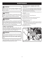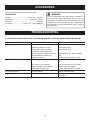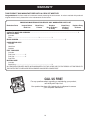
1
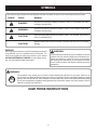
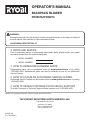
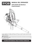
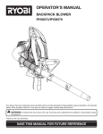
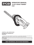
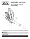
OPERATOR’S MANUAL BACKPACK BLOWER RY08576/RY09973 Your blower has been engineered and manufactured to our high standard for dependability, ease of operation, and operator safety. When properly cared for, it will give you years of rugged, trouble-free performance. WARNING: To reduce the risk of injury, the user must read and understand the operator’s manual before using this product. Thank you for your purchase. SAVE THIS MANUAL FOR FUTURE REFERENCE TABLE OF CONTENTS Introduction...................................................................................................................................................................... 2 General Safety Rules........................................................................................................................................................ 3 Specific Safety Rules........................................................................................................................................................ 4 Symbols......................................................................................................................................................................... 5-6 Features......................................................................................................................................................................... 7-8 Assembly..................................................................................................................................................................... 8-10 Operation................................................................................................................................................................... 10-12 Maintenance.............................................................................................................................................................. 13-14 Accessories.................................................................................................................................................................... 15 Troubleshooting.............................................................................................................................................................. 15 Warranty.................................................................................................................................................................... 16-18 Parts Ordering / Service................................................................................................................................................. 20 INTRODUCTION This product has many features for making its use more pleasant and enjoyable. Safety, performance, and dependability have been given top priority in the design of this product making it easy to maintain and operate. GENERAL SAFETY RULES Keep firm footing and balance. Do not overreach. Overreaching can result in loss of balance or exposure to hot surfaces. Never operate the unit without a spark arrestor screen; this screen is located inside the muffler. Product users on United States Forest Service land, and in some states, must comply with fire prevention regulations. This product is equipped with a spark arrestor; however, other user requirements may apply. Check with the federal, state, or local authorities in your area. Before storing, allow the engine to cool. WARNING: Read and understand all instructions. Failure to follow all instructions listed below may result in electric shock, fire and/or carbon monoxide poisoning which will cause death or serious personal injury. Do not allow children or untrained individuals to use this unit. Never start or run the engine inside a closed area; breathing exhaust fumes can kill. Wear eye protection which is marked to comply with ANSI Z87.1 as well as hearing protection when operating this equipment. Keep all bystanders, children, and pets at least 50 feet away. Wear heavy long pants, boots, and gloves. Do not wear loose fitting clothing, short pants, jewelry of any kind, or go barefoot. To reduce the risk of injury associated with objects being drawn into rotating parts, do not wear loose clothing, scarves, neck chains, and the like. Secure long hair so it is above shoulder level to prevent entanglement in any rotating parts. Do not operate this unit when you are tired, ill, or under the influence of alcohol, drugs, or medication. Do not operate in poor lighting. Use only Ryobi replacement parts and accessories. Failure to do so may cause poor performance or possible injury. Maintain the unit per maintenance instructions in this operator’s manual. Inspect the unit before each use for loose fasteners, fuel leaks, etc. Replace damaged parts. SERVICE Before cleaning, repairing, or inspecting, shut off the engine and make certain all moving parts have stopped. Disconnect the spark plug wire, and keep the wire away from the plug to prevent starting. Service on the blower must be performed by qualified repair personnel only. Service or maintenance performed by unqualified personnel could result in injury to the user or damage to the product. Keep all parts of your body away from any moving parts and all hot surfaces of the unit. Wear a face filter mask in dusty conditions to reduce the risk of injury associated with the inhalation of dust. Check the work area before each use. Remove all objects such as rocks, broken glass, nails, wire, or string which can be thrown or become entangled in the machine. Use only identical replacement parts when servicing the blower. Use of unauthorized parts may create a risk of serious injury to the user, or damage to the product. specific SAFETY RULES Select bare ground, stop engine, and allow to cool before refueling. Loosen fuel cap slowly to release pressure and to keep fuel from escaping around the cap. Tighten the fuel cap securely after refueling. To reduce the risk of hearing loss associated with sound level(s), hearing protection is required. To reduce the risk of injury associated with contacting rotating parts, stop the engine before installing or removing attachments. Do not operate without guard(s) in place. Always disconnect the spark plug before performing maintenance or accessing any movable parts. Do not point the blower nozzle in the direction of people or pets. Never run the unit without the blower tubes installed. Wipe spilled fuel from the unit. Move 30 feet away from refueling site before starting engine. Never attempt to burn off spilled fuel under any circumstances. Store fuel in a cool, well-ventilated area, safely away from spark and/or flame-producing equipment. Never place objects inside the blower tubes. Never use for spreading chemicals, fertilizers, toxic substances, or any other hazardous chemical. Always hold the blower in your right hand. Refer to the Operation section later in this manual for additional information. Store fuel in containers specifically designed for this purpose. Only refuel outdoors and do not smoke while refueling. Add fuel before starting the engine. Never remove the cap of the fuel tank or add fuel while the engine is running or when the engine is hot. If fuel is spilled, do not attempt to start the engine but move the machine away from the area of spillage and avoid creating any source of ignition until fuel vapors have dissipated. refueling Fuel is highly flammable. Take precautions when using to reduce the chance of serious personal injury. Empty fuel tank and restrain the unit from moving before transporting in a vehicle. To reduce the risk of fire and burn injury, handle fuel with care. It is highly flammable. Do not smoke while handling fuel. Replace all fuel tank and container caps securely. When draining the fuel tank, use an approved fuel storage container while in a well-ventilated area. Save these instructions. Refer to them frequently and use them to instruct others who may use this product. If you loan someone this product, loan them these instructions also. Mix and store fuel in a container approved for gasoline. Mix fuel outdoors where there are no sparks or flames. SYMBOLS Some of the following symbols may be used on this product. Please study them and learn their meaning. Proper interpretation of these symbols will allow you to operate the product better and safer. SYMBOL NAME EXPLANATION Safety Alert Symbol Precautions that involve your safety. Read the Operator’s Manual To reduce the risk of injury, user must read and understand operator’s manual before using this product. Wear Eye and Hearing Protection Wear eye protection which is marked to comply with ANSI Z87.1 as well as hearing protection when operating this equipment. Long Hair Risk of long hair being drawn into air inlet. Loose Clothing Risk of loose clothing being drawn into air intake. Gasoline and Oil Use unleaded gasoline intended for motor vehicle use with an octane rating of 87 [(R + M) / 2] or higher. This product is powered by a 2-cycle engine and requires pre-mixing gasoline and 2-cycle oil. SYMBOLS The following signal words and meanings are intended to explain the levels of risk associated with this product. SYMBOL SIGNAL MEANING DANGER: Indicates an imminently hazardous situation, which, if not avoided, will result in death or serious injury. WARNING: Indicates a potentially hazardous situation, which, if not avoided, could result in death or serious injury. CAUTION: Indicates a potentially hazardous situation, which, if not avoided, may result in minor or moderate injury. CAUTION: (Without Safety Alert Symbol) Indicates a situation that may result in property damage. SERVICE Servicing requires extreme care and knowledge and should be performed only by a qualified service technician. For service we suggest you return the product to your nearest AUTHORIZED SERVICE CENTER for repair. When servicing, use only identical replacement parts. WARNING: To avoid serious personal injury, do not attempt to use this product until you read thoroughly and understand completely the operator’s manual. If you do not understand the warnings and instructions in the operator’s manual, do not use this product. Call Ryobi customer service for assistance. WARNING: The operation of any power tool can result in foreign objects being thrown into your eyes, which can result in severe eye damage. Before beginning power tool operation, always wear safety goggles or safety glasses with side shields and, when needed, a full face shield. We recommend Wide Vision Safety Mask for use over eyeglasses or standard safety glasses with side shields. Always use eye protection which is marked to comply with ANSI Z87.1. SAVE THESE INSTRUCTIONS FEATURES PRODUCT SPECIFICATIONS Weight...................................................................................................................................................................... 11.75 lbs. Engine displacement.....................................................................................................................................................25.4cc Air Velocity: MPH................................................................................................................................................................................160 CFM................................................................................................................................................................................375 harness height adjustments straight tube engine SHOULDER STRAP elbow mesh backing engine switch cable tie waist STRAP bellows throttle trigger throttle CONTROL handle tUBE CLAMP(S) nozzle THrottle control handle tube Fig. 1 FEATURES KNOW YOUR blower Cruise Control/throttle lock See Figure 1. The safe use of this product requires an understanding of the information on the tool and in this operator’s manual as well as a knowledge of the project you are attempting. Before use of this product, familiarize yourself with all operating features and safety rules. The cruise control (throttle lock) feature allows the user to operate the blower without holding the throttle trigger. mesh backing Adjustable harness and waist straps The blower has a powerful 25.4cc engine with sufficient power to handle tough jobs. The blower comes equipped with a mesh backing which aids in user comfort. MOTOR The blower comes with fully adjustable harness and waist straps to ensure user comfort and ease of operation. THROTTLE TRIGGER adjustable THROTTLE control handle The blower can be operated at any speed between idle and full throttle. Easily adjust throttle control handle by loosening handle knob to position handle in desired location. ASSEMBLY UNPACKING WARNING: This product requires assembly. n Carefully remove the product and any accessories from the box. Make sure that all items listed in the packing list are included. n Inspect the product carefully to make sure no breakage or damage occurred during shipping. n Do not discard the packing material until you have carefully inspected and satisfactorily operated the product. n If any parts are damaged or missing, please call 1-800-860-4050 for assistance. If any parts are damaged or missing do not operate this product until the parts are replaced. Failure to heed this warning could result in serious personal injury. WARNING: Do not attempt to modify this product or create accessories not recommended for use with this product. Any such alteration or modification is misuse and could result in a hazardous condition leading to possible serious personal injury. PACKING LIST Backpack Blower Bellows WARNING: Cable Tie (2) To prevent accidental starting that could cause serious personal injury, always disconnect the engine spark plug wire from the spark plug when assembling parts. Clamp Screws (3) Elbow Nozzle Straight Tube Throttle Control Handle Tube Tube Clamp (3) 2-Cycle Engine Oil Operator’s Manual NOTE: Read and remove all hang tags and store with your operator’s manual. ASSEMBLY WARNING: Disconnect the spark plug wire before assembling parts. Failure to do so could result in possible serious personal injury. ASSEMBLING THE BLOWER TUBES See Figures 2 - 4. Place a tube clamp on blower past the raised tabs. Assemble the elbow tube onto blower by aligning raised tabs on blower with slots on elbow. Tighten tube clamp onto elbow. elbow tube Attach bellows onto elbow tube by placing a tube clamp on one end of the bellows then press bellows onto elbow tube. Tighten tube clamp. bellows tUBE CLAMP Place a tube clamp on other end of bellows. Press bellows onto throttle control handle tube. Tighten tube clamp. throttle control handle tube NOTE: The position of the throttle control handle may be adjusted for comfort after the blower is strapped onto the operator’s back. throttle control handle tube Join the straight tube and nozzle together by aligning raised locking tabs on straight tube with the raised locking slots on nozzle and twist to secure. Assemble the connected lower tubes to the throttle control handle tube by aligning raised locking tabs on the throttle control handle tube with the raised locking slots on connected lower tubes by twisting to secure. Fig. 2 nozzle NOTE: Check all locking connections after initial run to ensure they are tightly secured. Hold the throttle cable against the bellows and install the cable ties. Cable ties should be tight enough to retain the throttle cable to the bellows but still allow for movement. STRAIGHT TUBE Fig. 3 throttle control handle tube throttle cable cable tie Fig. 4 ASSEMBLY To adjust waist strap assembly: Waist strap should be tightened or loosened until adjusted to a comfortable operating position. CAUTION: Make all adjustments to the harness straps before starting the blower to avoid the possibility of injury. ADJUSTING Throttle control handle See Figure 5. Loosen throttle control handle locking screw by twisting counterclockwise. Move throttle control handle to desired position and secure locking screw by twisting clockwise. ADJUSTING HARNESS and waist STRAPS Straps should be adjusted to a comfortable position before starting the blower. To adjust harness strap assembly: Blower should be in operating position before adjusting the harness straps. Slip arm through harness strap and onto shoulder, then repeat for the other shoulder. There are three possible height adjustment positions that can be used to easily adjust harness. throttle control handle Slip top buckle of harness from adjustment slot and position to desired height location. Tighten (pull down on strap) or loosen (lift up on tab of strap buckle) each harness strap as needed, until each is adjusted to a comfortable operating position. LOCKING SCREW Chest strap should be tightened or loosened until adjusted to a comfortable operating position. Fig. 5 OPERATION mixing the fuel WARNING: This product is powered by a 2-cycle engine and requires pre-mixing gasoline and 2-cycle oil. The mixture should be at a 50:1 ratio, using Premium Exact Mix™ 2-cycle engine oil. If Premium Exact Mix™ 2-cycle engine oil is not available, use a high quality synthetic 2-cycle engine oil, mixed at a 50:1 ratio. See chart later in this section. To mix the fuel: Use a clean container that is approved for use with gasoline. Mix the Premium Exact Mix™ 2-cycle engine oil with unleaded gasoline in the container, according to the instructions on the oil package. NOTE: This engine is certified to operate on unleaded gasoline intended for automotive use with an octane rating of 87 [(R + M) / 2] or higher. Do not use automotive oil or 2-cycle outboard oil. NOTE: Premium Exact Mix™ fuel mixture will stay fresh up to 30 days. DO NOT mix quantities larger than usable in a 30 day period. Do not allow familiarity with this product to make you careless. Remember that a careless fraction of a second is sufficient to inflict serious injury. WARNING: Always wear safety goggles or safety glasses with side shields when operating power tools. Failure to do so could result in objects being thrown into your eyes resulting in possible serious injury. APPLICATIONS You may use this product for the purposes listed below: Clear leaves and other debris from your lawn Keep decks and driveways free from leaves and pine needles WARNING: PREMIUM EXACT MIX™ (50:1) Gasoline is extremely flammable and explosive. A fire or explosion from gasoline will burn you and others. 10 Gasoline Oil 1 gallon (US)2.6 oz. 1 liter20 cc (20 ml) OPERATION FILLING THE TANK n Set the choke lever to the START position. WARNING: Pull the starter cord until the engine runs. Always stop the engine before filling the fuel tank. Never add fuel to a machine with a running or hot engine. Move at least 30 ft. from the refueling area before starting engine. Do not smoke while filling the tank. Return the starter cord gently to the starter housing. Do not allow the rope to snap back. Allow the engine to run for 15 seconds to warm up before using. Clean the surface around the fuel cap to prevent contamination. Loosen the fuel cap slowly, by turning it counterclockwise. Pour the fuel mixture carefully into the tank. Clean and inspect the fuel cap gasket before replacing the fuel cap. Replace the fuel cap and tighten it by turning it clockwise. Wipe spilled fuel from the product. Move at least 30 ft. away from refueling area before starting the product. Engage the throttle trigger to operate. To stop the blower: Release the throttle trigger. Press and hold the engine switch to the “O” or STOP position. To remove blower: Move harness straps off the shoulders. Let straps slide down arms. Grasp the straps and lower the blower to the ground. engine SWITCH WARNING: THROTTLE TRIGGER Check for fuel leaks. If you find any leaks, correct the problem before using the product. NOTE: If restarting a warm engine, leave the choke lever in the RUN position. WARNING: CRUisE CONTROL (THROTTLE LOCK) A leaking fuel cap is a fire hazard and must be replaced immediately. Fig. 6 STARTING AND STOPPING See Figures 6 - 7. NOTE: It is normal for smoke to be emitted from a new engine during first use. To start an engine that is cold or has run dry: n Fill the fuel tank, if necessary. Always use the proper oil/gasoline mixture. See Mixing the Fuel on page 10. choke lever choke lever start position run position n Disengage the cruise control lever. NOTE: Do not engage the throttle trigger during the starting process. n Slowly push the primer bulb seven times. Fig. 7 11 OPERATION WARNING proper operating position Keep away from all hot surfaces of the blower. Failure to do so could result in possible serious personal injury. OPERATING THE BLOWER See Figure 8. Start the blower. Refer to Starting and Stopping earlier in this manual. Slip arm through harness strap and onto shoulder, then repeat for the other shoulder. Adjust the straps to a comfortable position. Refer to Adjusting Harness and Waist Straps earlier in this manual. Operate the blower from the right side as shown in illustration. To keep from scattering debris, blow around the outer edges of a debris pile. Never blow directly into the center of a pile. Operate power equipment at reasonable hours only − not early in the morning or late at night when people might be disturbed. Comply with the times listed in local ordinances. To reduce sound levels, limit the number of pieces of equipment used at any one time. Operate blower at the lowest possible throttle speed to do the job. Conserve water by using power blowers instead of hoses for many lawn and garden applications, including areas such as gutters, screens, patios, grills, porches, and gardens. Check your equipment before operation, especially the muffler, air intakes, and air filters. Use rakes and brooms to loosen debris before blowing. In dusty conditions, slightly dampen surfaces when water is available. Watch out for children, pets, open windows or freshly washed cars, and blow debris safely away. Fig. 8 CRUisE CONTROL (THROTTLE LOCK) Use the nozzle for larger volume, so the air stream can work close to the ground. After using blowers or other equipment, CLEAN UP! Dispose of debris properly. Cruise control/THROTTLE LOCK tHROTTLE TRIGGER See Figure 9. The cruise control (throttle lock) can be used to operate the blower without holding the throttle trigger. To engage the cruise control/throttle lock: Fig. 9 Pull cruise control lever back toward user, and stop at the desired throttle setting. To release the cruise control, push cruise control lever all the way toward the front of unit. 12 MAINTENANCE replacing and cleaning air filter WARNING: See Figure 10. A wet or dirty air filter can affect the way the engine starts, performs, and wears. The air filter should be checked and cleaned after 8 hours of operation. If working in dusty soil, check the air filter after each refueling. For best performance, the air filter should be replaced once each year. To clean the air filter: nLoosen the knob on the air filter cover. When servicing, use only identical replacement parts. Use of any other parts may create a hazard or cause product damage. WARNING: Always wear safety goggles or safety glasses with side shields during power tool operation or when blowing dust. If operation is dusty, also wear a dust mask. nRemove the cover. nLift the edge of the air filter carefully and peel it out. nWash the air filter with warm, soapy water. WARNING: nRinse and squeeze to dry. Before inspecting, cleaning, or servicing the machine, shut off engine, wait for all moving parts to stop, and disconnect spark plug wire and move it away from spark plug. Failure to follow these instructions can result in serious personal injury or property damage. nReinstall the air filter. NOTE: Make sure the filter is seated properly inside the cover. Installing the filter incorrectly will allow dirt to enter the engine, causing rapid engine wear. nReinstall the cover. nTighten knob to secure. GENERAL MAINTENANCE Avoid using solvents when cleaning plastic parts. Most plastics are susceptible to damage from various types of commercial solvents and may be damaged by their use. Use clean cloths to remove dirt, dust, oil, grease, etc. AIR FILTER knob WARNING: Do not at any time let brake fluids, gasoline, petroleumbased products, penetrating oils, etc., come in contact with plastic parts. Chemicals can damage, weaken or destroy plastic which may result in serious personal injury. Only the parts shown on the parts list are intended to be repaired or replaced by the customer. All other parts should be replaced at an Authorized Service Center. AIR FILTER COVER 13 Fig. 10 MAINTENANCE SPARK ARRESTOR WARNING: The muffler is equipped with a spark arrestor screen inside muffler body. After extended use the screen can become dirty and the screen may need to be replaced by an authorized servicing dealer. A leaking fuel cap is a fire hazard and must be replaced immediately. SPARK PLUG This engine uses a Champion RCJ6Y with 0.63 mm (0.025 in.) electrode gap. Use an exact replacement and replace annually. WARNING: To avoid a fire hazard, never run the blower without the spark arrestor in place. STORing the product CLEANING THE EXHAUST PORT AND MUFFLER Clean all foreign material from the product. Store it in a well-ventilated place that is inaccessible to children. Keep away from corrosive agents such as garden chemicals and de-icing salts. Abide by all Federal and local regulations for the safe storage and handling of gasoline. WHEN STORING 1 MONTH OR LONGER: Drain all fuel from tank into a container approved for gasoline. Run engine until it stops. Depending on the type of fuel used, the type and amount of oil used, and/or your operating conditions, the exhaust port, muffler, and/or spark arrestor screen may become blocked with carbon deposits. If you notice a power loss with your gas powered tool, you may need to remove these deposits to restore performance. We highly recommend that only qualified service technicians perform this service. FUEL CAP The fuel cap contains a non-serviceable filter and a check valve. A clogged fuel filter will cause poor engine performance. If performance improves when the fuel cap is loosened, the check valve may be faulty or filter clogged. Replace the fuel cap if required. 14 accessories Look for these accessories at the service center: ACCESSORIES Air Filter.......................................... Power Care - AP04107 Spark Plug............................................Champion - RCJ6Y Fuel Cap............................................................... AP04108 2-Cycle Oil........................... (2.6 FL. OZ - 76 ml) AR99G01 WARNING: Current attachments and accessories available for use with this product are listed. Do not use any attachments or accessories not recommended by the manufacturer of this product. The use of attachments or accessories not recommended can result in serious personal injury. TROUBLESHOOTING IF THESE SOLUTIONS DO NOT SOLVE THE PROBLEM, CONTACT YOUR AUTHORIZED SERVICING DEALER. Problem Engine fails to start Cause Remedy No fuel in tank Fill tank. Spark plug shorted or fouled Replace spark plug. Spark plug is broken (cracked porcelain or electrodes broken) Replace spark plug. Ignition lead wire shorted, broken, or disconnected from spark plug Replace lead wire or attach to spark plug. Ignition inoperative Contact authorized service center. Water in gasoline or stale fuel mixture Drain entire system and refill with fresh fuel. Too much oil in fuel mixture Drain and refill with correct mixture. Engine is under or over choked Adjust choke as necessary. Weak spark at spark plug Contact authorized service center. Engine lacks power Air filter clogged Clean or replace air filter. Engine overheats Insufficient oil in fuel mixture Mix fuel as described in starting instructions. Engine hard to start 15 WARRANTY LIMITED WARRANTY STATEMENT A.Tune-ups – Spark Plugs, Carburetor, Carburetor Adjustments, Ignition, Filters B. Wear items – Bump Knobs, Outer Spools, Cutting Lines, Inner Reels, Starter Pulleys, Starter Ropes, Drive Belts, Tines, Felt Washers, Hitch Pins, Mulching Blades, Blower Fans, Blower and Vacuum Tubes, Vacuum Bag and Straps, Guide Bars, Saw Chains Techtronic Industries North America, Inc., reserves the right to change or improve the design of any RYOBI® brand outdoor product without assuming any obligation to modify any product previously manufactured. Techtronic Industries North America, Inc., warrants to the original retail purchaser that this Ryobi® brand outdoor product is free from defect in material and workmanship and agrees to repair or replace, at Techtronic Industries North America, Inc.’s, discretion, any defective product free of charge within these time periods from the date of purchase. Two years if the product is used for personal, family or household use; 90 days, if used for any other purpose, such as commercial or rental. This warranty extends to the original retail purchaser only and commences on the date of the original retail purchase. Any part of this product found in the reasonable judgment of Techtronic Industries North America, Inc. to be defective in material or workmanship will be repaired or replaced without charge for parts and labor by an authorized service center for RYOBI® brand outdoor products (Authorized Ryobi Service Center). The product, including any defective part, must be returned to an authorized Ryobi service center within the warranty period. The expense of delivering the product to the service center for warranty work and the expense of returning it back to the owner after repair or replacement will be paid by the owner. Techtronic Industries North America, Inc.’s, responsibility in respect to claims is limited to making the required repairs or replacements and no claim of breach of warranty shall be cause for cancellation or rescission of the contract of sale of any RYOBI® brand outdoor product. Proof of purchase will be required by the dealer to substantiate any warranty claim. All warranty work must be performed by an authorized service dealer. This warranty is limited to ninety (90) days from the date of original retail purchase for any RYOBI® brand outdoor product that is used for rental or commercial purposes, or any other income-producing purpose. This warranty does not cover any product that has been subject to misuse, neglect, negligence, or accident, or that has been operated in any way contrary to the operating instructions as specified in this operator’s manual. This warranty does not apply to any damage to the product that is the result of improper maintenance or to any product that has been altered or modified. The warranty does not extend to repairs made necessary by normal wear or by the use of parts or accessories which are either incompatible with the RYOBI® brand outdoor product or adversely affect its operation, performance, or durability. In addition, this warranty does not cover: ALL IMPLIED WARRANTIES ARE LIMITED IN DURATION TO THE STATED WARRANTY PERIOD. ACCORDINGLY, ANY SUCH IMPLIED WARRANTIES INCLUDING MERCHANTABILITY, FITNESS FOR A PARTICULAR PURPOSE, OR OTHERWISE, ARE DISCLAIMED IN THEIR ENTIRETY AFTER THE EXPIRATION OF THE APPROPRIATE TWO-YEAR, ONE-YEAR, OR NINETYDAY WARRANTY PERIOD. Techtronic Industries North America, Inc.’s, OBLIGATION UNDER THIS WARRANTY IS STRICTLY AND EXCLUSIVELY LIMITED TO THE REPAIR OR REPLACEMENT OF DEFECTIVE PARTS AND Techtronic Industries North America, Inc., DOES NOT ASSUME OR AUTHORIZE ANYONE TO ASSUME FOR THEM ANY OTHER OBLIGATION. SOME STATES DO NOT ALLOW LIMITATIONS ON HOW LONG AN IMPLIED WARRANTY LASTS, SO THE ABOVE LIMITATION MAY NOT APPLY TO YOU. Techtronic Industries North America, Inc., ASSUMES NO RESPONSIBILITY FOR INCIDENTAL, CONSEQUENTIAL, OR OTHER DAMAGES INCLUDING, BUT NOT LIMITED TO, EXPENSE OF RETURNING THE PRODUCT TO AN AUTHORIZED ryobi SERVICE center AND EXPENSE OF DELIVERING IT BACK TO THE OWNER, MECHANIC’S TRAVEL TIME, TELEPHONE OR TELEGRAM CHARGES, RENTAL OF A LIKE PRODUCT DURING THE TIME WARRANTY SERVICE IS BEING PERFORMED, TRAVEL, LOSS OR DAMAGE TO PERSONAL PROPERTY, LOSS OF REVENUE, LOSS OF USE OF THE PRODUCT, LOSS OF TIME, OR INCONVENIENCE. SOME STATES DO NOT ALLOW THE EXCLUSION OR LIMITATION OF INCIDENTAL OR CONSEQUENTIAL DAMAGES, SO THE ABOVE LIMITATION OR EXCLUSION MAY NOT APPLY TO YOU. This warranty gives you specific legal rights, and you may also have other rights which vary from state to state. This warranty applies to all RYOBI® brand outdoor products manufactured by or for Techtronic Industries North America, Inc., and sold in the United States and Canada. To locate your nearest Authorized Ryobi Service Center, dial 1-800-860-4050. 16 WARRANTY The following California Air Resources Board (CARB) statement only applies to model numbers required to meet the CARB requirements. TECHTRONIC INDUSTRIES NORTH AMERICA, INC., LIMITED WARRANTY STATEMENT FOR FEDERAL AND CALIFORNIA EMISSION CONTROL SYSTEMS NON-ROAD AND SMALL OFF-ROAD ENGINES YOUR WARRANTY RIGHTS AND OBLIGATIONS The U.S. Environmental Protection Agency (EPA), the California Air Resources Board (CARB), and Techtronic Industries North America, Inc., are pleased to explain the Emissions Control System Warranty on your 2008 model year non-road or small offroad engine. In California, new equipment that uses small off-road engines must be designed, built, and equipped to meet the state’s stringent anti-smog standards. In other states, new 2000 and later model year non-road engines must be designed, built, and equipped at the time of sale to meet the U.S. EPA regulations for small non-road engines. The non-road engine must be free from defects in materials and workmanship which cause it to fail to conform with U.S. EPA standards for the first two years of engine use from the date of sale to the ultimate purchaser. Techtronic Industries North America, Inc., must warrant the emission control system on your non-road or small off-road engine for the period of time listed above provided there has been no abuse, neglect, or improper maintenance of your non-road or small off-road engine. Your emission control system may include parts such as the carburetor or fuel injection system, the ignition system, catalytic converters, fuel tanks, valves, filters, clamps, connectors, and other associated components. Also included may be hoses, belts and connectors, and other emission-related assemblies. Where a warrantable condition exists, Techtronic Industries North America, Inc., will repair your non-road or small off-road engine at no cost to you, including diagnosis, parts, and labor performed at an authorized service center for RYOBI® brand outdoor products. Techtronic Industries North America, Inc., shall remedy warranty defects at any authorized RYOBI® Authorized Service Center, including any distribution center that may be franchised to service the subject engines. Any diagnostic work done at a RYOBI® Authorized Service Center shall be free of charge to the owner if such work determines that a warranted part is defective. Any manufacturer-approved or equivalent replacement part may be used for any warranty maintenance or repairs on emission-related parts, and must be provided free of charge to the owner if the part is still under warranty. Techtronic Industries North America, Inc., is liable for damages to other engine components caused by the failure of a warranted part still under warranty. Add-on or modified parts that are not exempted by the California Air Resource Board may not be used. The use of any non-exempted add-on or modified parts will be grounds for disallowing a warranty claim. Techtronic Industries North America, Inc., will not be liable to warrant failures of warranted parts caused by the use of a nonexempted add-on or modified part. The California Air Resources Board’s Emission Warranty Parts List specifically defines the emission-related warranted parts. (EPA’s regulations do not include a parts list, but the EPA considers emission-related warranted parts to include all the parts listed below.) Techtronic Industries North America, Inc., will provide any documents that describe its warranty procedures or policies within five days upon request by the California Air Resources Board. MANUFACTURER’S WARRANTY COVERAGE: Emissions parts vary from product to product. Your emissions control system warranty applies to any of the following components that may be included on your product: (1) Fuel Metering System (i) Carburetor and internal parts (and/or pressure regulator or fuel injection system). (ii) Air/fuel ratio feedback and control system. (iii) Cold start enrichment system. (iv) Fuel Tank. (2) Air Induction System (i) Controlled hot air intake system. (ii) Intake manifold. (iii) Air filter. (3) Ignition System (i) Spark Plugs. (ii) Magneto or electronic ignition system. (iii) Spark advance/retard system. (4) Exhaust Gas Recirculation (EGR) System (i) EGR valve body and carburetor spacer, if applicable. (ii) EGR rate feedback and control system. (5) Air Injection System (i) Air pump or pulse valve. (ii) Valves affecting distribution of flow. (iii) Distribution manifold. (6) Catalyst or Thermal Reactor System (i) Catalytic converter. (ii) Thermal reactor. (iii) Exhaust manifold. (7) Particulate Controls (i) Traps, filters, precipitators, and any other device used to capture particulate emissions. (8) Miscellaneous Items Used in Above Systems (i) Electronic controls. (ii) Vacuum, temperature, and time sensitive valves and switches. (iii) Hoses, belts, connectors, and assemblies. Techtronic Industries North America, Inc., will furnish with each new engine written instructions for its maintenance and use by the owner. The Emissions Compliance Period referred to on the Emissions Compliance label indicates the number of operating hours for which the engine has been shown to meet Federal emission requirements. Category C=50 hours, B=125 hours, and A=300 hours. EMISSIONS PARTS LIST This product’s emissions control system is warranted for two years. If any emission-related part on your engine is defective, the part will be repaired or replaced by Techtronic Industries North America, Inc., free of charge. OWNER’S WARRANTY RESPONSIBILITIES (a) As the non-road or small off-road engine owner, you are responsible for the performance of the required maintenance listed in your operator’s manual. Techtronic Industries North America, Inc., recommends that you retain all receipts covering maintenance on your non-road or small off-road engine, but Techtronic Industries North America, Inc., cannot deny warranty solely for the lack of receipts or for your failure to ensure the performance of all scheduled maintenance. Any replacement part or service that is equivalent in performance and durability may be used in non-warranty maintenance or repairs, and shall not reduce the warranty obligations of Techtronic Industries North America, Inc. (b) As the non-road or small off-road engine owner, you should be aware, however, that Techtronic Industries North America, Inc., may deny you warranty coverage if your non-road or small off-road engine or a part has failed due to abuse, neglect, improper maintenance, or unapproved modifications. (c) You are responsible for presenting your non-road or small off-road engine to an authorized service dealer as soon as a problem exists. The warranty repairs should be completed in a reasonable amount of time, not to exceed 30 days. If you have any questions regarding your warranty rights and responsibilities, you should contact a Techtronic Industries North America, Inc., Customer Representative at 1-800-860-4050. DEFECT WARRANTY COVERAGE REQUIREMENTS: (a) The warranty period begins on the date the engine or equipment is delivered to an ultimate purchaser. (b) General Emissions Warranty Coverage. Techtronic Industries North America, Inc., warrants to the ultimate purchaser and each subsequent purchaser that your non-road or small off-road engine is designed, built, and equipped at the time of sale to conform with all applicable regulations adopted by the California Air Resources Board or the United States Environmental Protection Agency; and that it is free from defects in materials and workmanship which cause the engine to fail to conform with applicable regulations for a period of two years from the date the non-road or small off-road engine is purchased by the initial purchaser. (c) The warranty on emissions-related parts will be interpreted as follows: Any warranted part that is not scheduled for replacement as required in the Emissions Maintenance Schedule and Warranty Parts List set forth below is warranted for two years. If any such part (including any part that is scheduled only for regular inspection) fails during the period of warranty coverage, it will be repaired or replaced at any RYOBI® Authorized Service Center at no charge. Any such part repaired or replaced under warranty will be warranted for the remaining warranty period. A statement to the effect of “repair or replace as necessary” would not reduce the period of warranty coverage. Any warranted part that is scheduled for replacement as required maintenance in the Emissions Maintenance Schedule and Warranty Parts List is warranted for the period of time prior to the first scheduled replacement point for that part. Any such part repaired or replaced under warranty is warranted for the remainder of the period prior to the first scheduled replacement point, and will be repaired or replaced at any RYOBI® Authorized Service Center for no charge until that replacement point is reached. 17 warranty this product was manufactured with a catalyst muffler Congratulations! You have made an investment toward protecting the environment. In order to maintain this product’s original emission level, please refer to the maintenance section below. EMISSIONS MAINTENANCE SCHEDULE AND WARRANTED PARTS LIST Emissions Parts Inspect Before Clean Every Each Use 5 Hours Replace Every 25 Hours or Yearly Clean Every 25 Hours or Yearly Replace Every 50 Hours CATALYTIC MUFFLER ASSEMBLY.................................................................................................................... X AIR FILTER ASSY includes: Filter.................................................................. X.............................. X SPARK SCREEN................................................................................................................... X CARBURETOR ASSY includes: Heat Dam Gaskets FUEL TANK ASSY includes: Fuel Lines......................... X Fuel Cap........................... X Fuel Filter IGNITION ASSY includes: Spark Plug......................................................................................... X ALL EMISSIONS-RELATED PARTS ARE WARRANTED FOR TWO YEARS OR FOR THE PERIOD OF TIME PRIOR TO THE PARTS FIRST SCHEDULED REPLACEMENT WHICHEVER COMES FIRST. CALL US FIRST CALL 50 1-800-860-40 m ols.co yobito www.r For any questions about operating or maintaining your product, call the Ryobi® Help Line! Your product has been fully tested prior to shipment to ensure your complete satisfaction. 18 notes 19 OPERATOR’S MANUAL BACKPACK BLOWER RY08576/RY09973 WARNING: The engine exhaust from this product contains chemicals known to the state of california to cause cancer, birth defects or other reproductive harm. CALIFORNIA PROPOSITION 65 • Parts and Service Prior to requesting service or purchasing replacement parts, please obtain your model and serial number from the product data plate. • MODEL NUMBER • SERIAL NUMBER • How to obtain Replacement Parts: Replacement parts can be purchased online at www.ryobitools.com or by calling 1-800-860-4050. Replacement parts can also be obtained at one of our Authorized Service Centers. • How to locate an Authorized Service Center: Authorized Service Centers can be located online at www.ryobitools.com or by calling 1-800-860-4050. • How to obtain Customer or Technical Support: To obtain Customer or Technical Support please contact us at 1-800-860-4050. Ryobi® is a registered trademark of Ryobi Limited used under license. TECHTRONIC INDUSTRIES NORTH AMERICA, INC. 1428 Pearman Dairy Road Anderson, SC 29625 Phone 1-800-860-4050 www.ryobitools.com 987000-083 8-11-08 (REV:01)