1
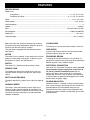
OPERATOR'S MANUAL
RE1802M1 ROUTER
With R181FB1 Fixed Base, R181PB1 Plunge
Base, and R181DB1 D-Handle Base
Double Insulated
1/ 3
2
01
3/
2
15/32
7/16
13 / 32
Your new router has been engineered and manufactured to our Ryobi’s high standard for dependability, ease of
operation, and operator safety. When properly cared for, the router will give you years of rugged, trouble-free
performance.
WARNING:
To reduce the risk of injury, the user must read and understand the operator’s manual before using this product.
Thank you for buying a Ryobi product.
SAVE THIS MANUAL FOR FUTURE REFERENCE
TABLE OF CONTENTS
■
Introduction .................................................................................................................................................................... 2
■
General Safety Rules .................................................................................................................................................. 3-4
■
Specific Safety Rules ..................................................................................................................................................... 4
■
Symbols ...................................................................................................................................................................... 5-6
■
Electrical ........................................................................................................................................................................ 7
■
Features ...................................................................................................................................................................... 8-9
■
Unpacking ...................................................................................................................................................................... 9
■
Operation ................................................................................................................................................................. 10-22
■
Maintenance ................................................................................................................................................................. 23
■
Accessories ................................................................................................................................................................. 23
■
Parts, Ordering, and Service ......................................................................................................................................... 24
INTRODUCTION
This router has many features for making its use more pleasant and enjoyable. Safety, performance, and dependability
have been given top priority in the design of this tool making it easy to maintain and operate.
2
GENERAL SAFETY RULES
■ Keep your work area clean and well lit. Cluttered
benches and dark areas invite accidents.
■ Do not operate power tools in explosive atmospheres, such as in the presence of flammable
liquids, gases, or dust. Power tools create sparks
which may ignite the dust or fumes.
■ Keep bystanders, children, and visitors away while
operating a power tool. Distractions can cause you to
lose control.
■ Avoid accidental starting. Be sure switch is off before
plugging in. Carrying tools with your finger on the switch or
plugging in tools that have the switch on, invites accidents.
■ Remove adjusting keys or wrenches before turning
the tool on. A wrench or a key that is left attached to a
rotating part of the tool may result in personal injury.
■ Do not overreach. Keep proper footing and balance
at all times. Proper footing and balance enables better
control of the tool in unexpected situations.
■ Use safety equipment. Always wear eye protection.
Dust mask, non-skid safety shoes, hard hat, or hearing
protection must be used for appropriate conditions.
■ Do not wear loose clothing or jewelry. Contain long
hair. Loose clothes, jewelry, or long hair can be drawn
into air vents.
■ Do not use on a ladder or unstable support. Stable
footing on a solid surface enables better control of the
tool in unexpected situations.
ELECTRICAL SAFETY
TOOL USE AND CARE
■ Double insulated tools are equipped with a polarized
plug (one blade is wider than the other). This plug
will fit in a polarized outlet only one way. If the plug
does not fit fully in the outlet, reverse the plug. If it
still does not fit, contact a qualified electrician to
install a polarized outlet. Do not change the plug in
eliminates the need for
any way. Double insulation
the three-wire grounded power cord and grounded power
supply system.
■ Avoid body contact with grounded surfaces such as
pipes, radiators, ranges, and refrigerators. There is an
increased risk of electric shock if your body is grounded.
■ Don’t expose power tools to rain or wet conditions.
Water entering a power tool will increase the risk of electric
shock.
■ Do not abuse the cord. Never use the cord to carry the
tools or pull the plug from an outlet. Keep cord away
from heat, oil, sharp edges, or moving parts. Replace
damaged cords immediately. Damaged cords increase
the risk of electric shock.
■ When operating a power tool outside, use an outdoor
extension cord marked “W-A” or “W”. These cords are
rated for outdoor use and reduce the risk of electric shock.
■ Use clamps or other practical way to secure and
support the workpiece to a stable platform. Holding
the work by hand or against your body is unstable and
may lead to loss of control.
■ Do not force tool. Use the correct tool for your
application. The correct tool will do the job better and
safer at the rate for which it is designed.
■ Do not use tool if switch does not turn it on or off.
Any tool that cannot be controlled with the switch is
dangerous and must be repaired.
■ Disconnect the plug from power source before
making any adjustments, changing accessories, or
storing the tool. Such preventive safety measures
reduce the risk of starting the tool accidentally.
■ Store idle tools out of the reach of children and other
untrained persons. Tools are dangerous in the hands of
untrained users.
■ Maintain tools with care. Keep cutting tools sharp
and clean. Properly maintained tools with sharp cutting
edges are less likely to bind and are easier to control.
■ Check for misalignment or binding of moving parts,
breakage of parts, and any other condition that may
affect the tool’s operation. If damaged, have the tool
serviced before using. Many accidents are caused by
poorly maintained tools.
■ Use only accessories that are recommended by the
manufacturer for your model. Accessories that may be
suitable for one tool, may become hazardous when used
on another tool.
■ Keep the tool and its handle dry, clean and free from
oil and grease. Always use a clean cloth when cleaning.
Never use brake fluids, gasoline, petroleum-based
products, or any strong solvents to clean your tool.
Following this rule will reduce the risk of loss of control
and deterioration of the enclosure plastic.
WARNING:
Read and understand all instructions. Failure to follow
all instructions listed below, may result in electric shock,
fire and/or serious personal injury.
SAVE THESE INSTRUCTIONS
WORK AREA
PERSONAL SAFETY
■ Stay alert, watch what you are doing and use common sense when operating a power tool. Do not use
tool while tired or under the influence of drugs,
alcohol, or medication. A moment of inattention while
operating power tools may result in serious personal
injury.
■ Dress properly. Do not wear loose clothing or jewelry. Contain long hair. Keep your hair, clothing, and
gloves away from moving parts. Loose clothes,
jewelry, or long hair can be caught in moving parts.
3
GENERAL SAFETY RULES
■ When servicing a tool, use only identical replacement parts. Follow instructions in the Maintenance
section of this manual. Use of unauthorized parts or
failure to follow Maintenance Instructions may create a
risk of electric shock or injury.
SERVICE
■ Tool service must be performed only by qualified
repair personnel. Service or maintenance performed by
unqualified personnel could result in a risk of injury.
SPECIFIC SAFETY RULES
■ Hold tool by insulated gripping surfaces when performing an operation where the cutting tools may contact
hidden wiring or its own cord. Contact with a “live” wire will make exposed metal parts of the cutting tool “live” and
shock the operator.
■ Make sure your extension cord is in good condition.
When using an extension cord, be sure to use one
heavy enough to carry the current your product will
draw. A wire gage size (A.W.G.) of at least 14 is
recommended for an extension cord 50 feet or less
in length. A cord exceeding 50 feet is not recommended. If in doubt, use the next heavier gage. The
smaller the gage number, the heavier the cord. An
undersized cord will cause a drop in line voltage resulting in loss of power and overheating.
■ Inspect for and remove all nails from lumber before
routing. Following this rule will reduce the risk of
serious personal injury.
■ Drugs, alcohol, medication. Do not operate tool
while under the influence of drugs, alcohol, or any
medication. Following this rule will reduce the risk of
electric shock, fire, or serious personal injury.
■ Save these instructions. Refer to them frequently and
use them to instruct others who may use this tool. If you
loan someone this tool, loan them these instructions
also.
ADDITIONAL SAFETY RULES
■ Know your power tool. Read operator’s manual
carefully. Learn its applications and limitations, as
well as the specific potential hazards related to this
tool. Following this rule will reduce the risk of electric
shock, fire, or serious injury.
■ Always wear safety glasses. Everyday eyeglasses
have only impact-resistant lenses; they are NOT
safety glasses. Following this rule will reduce the risk of
serious personal injury.
■ Protect your lungs. Wear a face or dust mask if the
operation is dusty. Following this rule will reduce the
risk of serious personal injury.
■ Protect your hearing. Wear hearing protection during
extended periods of operation. Following this rule will
reduce the risk of serious personal injury.
■ Inspect tool cords periodically and, if damaged, have
repaired at your nearest authorized service center.
Constantly stay aware of cord location. Following this
rule will reduce the risk of electric shock or fire.
■ Check damaged parts. Before further use of the tool,
a guard or other part that is damaged should be
carefully checked to determine that it will operate
properly and perform its intended function. Check for
alignment of moving parts, binding of moving parts,
breakage of parts, mounting, and any other conditions that may affect its operation. A guard or other
part that is damaged should be properly repaired or
replaced by an authorized service center. Following
this rule will reduce the risk of shock, fire, or serious
injury.
■ Do not abuse cord. Never carry the tool by the cord
or yank it to disconnect it from the receptacle. Keep
cord away from heat, oil, and sharp edges. Following
this rule will reduce the risk of electric shock or fire.
WARNING:
Some dust created by power sanding, sawing, grinding,
drilling, and other construction activities contains chemicals known to cause cancer, birth defects or other reproductive harm. Some examples of these chemicals are:
• lead from lead-based paints,
• crystalline silica from bricks and cement and
other masonry products, and
• arsenic and chromium from chemically-treated
lumber.
Your risk from these exposures varies, depending on how
often you do this type of work. To reduce your exposure
to these chemicals: work in a well ventilated area, and
work with approved safety equipment, such as those dust
masks that are specially designed to filter out microscopic particles.
4
SYMBOLS
Some of the following symbols may be used on this tool. Please study them and learn their meaning. Proper interpretation of
these symbols will allow you to operate the tool better and safer.
SYMBOL
NAME
DESIGNATION/EXPLANATION
V
Volts
Voltage
A
Amperes
Current
Hz
Hertz
Frequency (cycles per second)
W
Watt
Power
Minutes
Time
Alternating Current
Type of current
Direct Current
Type or a characteristic of current
No Load Speed
Rotational speed, at no load
Class II Construction
Double-insulated construction
Per Minute
Revolutions, strokes, surface speed, orbits etc., per minute
Wet Conditions Alert
Do not expose to rain or use in damp locations.
min
---
no
.../min
Read The Operator’s Manual
To reduce the risk of injury, the user must read and understand
the operator’s manual before using this product.
Eye Protection
Always wear safety goggles or safety glasses with side shields
and a full face shield when operating this product.
Safety Alert
Precautions that involve your safety.
No Hands Symbol
Failure to keep your hands away from the blade will result in
serious personal injury.
No Hands Symbol
Failure to keep your hands away from the blade will result in
serious personal injury.
No Hands Symbol
Failure to keep your hands away from the blade will result in
serious personal injury.
No Hands Symbol
Failure to keep your hands away from the blade will result in
serious personal injury.
5
SYMBOLS
The following signal words and meanings are intended to explain the levels of risk associated with this
product.
SYMBOL
MEANING
DANGER:
Indicates an imminently hazardous situation, which, if not avoided, will result in
death or serious injury.
WARNING:
Indicates a potentially hazardous situation, which, if not avoided, could result in
death or serious injury.
CAUTION:
Indicates a potentially hazardous situation, which, if not avoided, may result in
minor or moderate injury.
(Without Safety Alert Symbol) Indicates a situation that may result in property
damage.
SERVICE
Servicing requires extreme care and knowledge and should be
performed only by a qualified service technician. For service
we suggest you return the product to your nearest
AUTHORIZED SERVICE CENTER for repair. When servicing,
use only identical replacement parts.
WARNING:
To avoid serious personal injury, do not attempt to use
this product until you read thoroughly and understand
completely the operator's manual. Save this operator's
manual and review frequently for continuing safe operation and instructing others who may use this product.
WARNING:
Observe all normal safety precautgions related to avoiding electrical shock.
WARNING:
The operation of any tool can result in foreign objects being thrown into your eyes, which can result in severe
eye damage. Before beginning operation, always wear safety goggles or safety glasses with side shields and a
full face shield when needed. We recommend Wide Vision Safety Mask for use over eyeglasses or standard
safety glasses with side shields. Always wear eye protection which is marked to comply with ANSI Z87.1.
SAVE THESE INSTRUCTIONS
6
ELECTRICAL
DOUBLE INSULATION
EXTENSION CORDS
Double insulation is a concept in safety in electric power
tools, which eliminates the need for the usual three-wire
grounded power cord. All exposed metal parts are
isolated from the internal metal motor components with
protecting insulation. Double insulated tools do not need
to be grounded.
Important: Servicing of a tool with double insulation
requires extreme care and knowledge of the system and
should be performed only by a qualified service
technician. For service, we suggest you return the tool to
your nearest authorized service center for repair. When
servicing, use only identical Ryobi replacement parts.
When using a power tool at a considerable distance from
a power source, be sure to use an extension cord that
has the capacity to handle the current the tool will draw.
An undersized cord will cause a drop in line voltage,
resulting in overheating and loss of power. Use the chart
to determine the minimum wire size required in an
extension cord. Only round jacketed cords listed by
Underwriter’s Laboratories (UL) should be used.
When working outdoors with a tool, use an extension cord
that is designed for outside use. This type of cord is
designated with “WA” on the cord’s jacket.
Before using any extension cord, inspect it for loose or
exposed wires and cut or worn insulation.
WARNING:
**Ampere rating (on tool faceplaate)
0-2.0
2.1-3.4
The double insulated system is intended to protect the
user from shock resulting from a break in the tool's
internal wiring. Observe all normal safety precautions
related to avoiding electrical shock.
Cord Length
ELECTRICAL CONNECTION
The router has a precision built electric motor. It should
be connected to a power supply that is 120 volts, 60 Hz,
AC only (normal household current). Do not operate this
tool on direct current (DC). A substantial voltage drop will
cause a loss of power and the motor will overheat. If your
tool does not operate when plugged into an outlet,
double-check the power supply.
3.5-5.0
5.1-7.0
7.1-12.0
12.1-16.0
Wire Size (A.W.G.)
25'
16
16
16
16
14
14
50'
16
16
16
14
14
12
100'
16
16
14
12
10
—
**Used on 12 gauge - 20 amp circuit.
WARNING:
Keep the extension cord clear of the working area. Position the cord so that it will not get caught on lumber, tools
or other obstructions while you are working with a power
tool. Failure to do so can result in serious personal injury.
WARNING:
Check extension cords before each use. If damaged replace immediately. Never use tool with a damaged cord
since touching the damaged area could cause electrical
shock resulting in serious injury.
7
FEATURES
SPECIFICATIONS
Depth of Cut:
Plunge Base ............................................................................................................................ 0 - 2 in. (0 - 51 mm)
Fixed Base & D-Base ........................................................................................................ 0 - 1-1/2 in. (0 - 38 mm)
Collet ........................................................................................................................................................ 1/2 in. (12.7 mm)
Collet Adaptor ............................................................................................................................................... 1/4 in. (6 mm)
Peak Horsepower ................................................................................................................................................................ 2
Ampere ................................................................................................................................................................... 10 Amps
Input ............................................................................................................................................ 120 Volts, 60 Hz, AC only
No Load Speed .................................................................................................................................... 15,000 - 25,000 RPM
Power Cord ......................................................................................................................................................... 10 ft. (3 m)
Total Net Weight .......................................................................................................................................... 19 lbs. (8.6 kg.)
Before using this tool, familiarize yourself with all operating features and safety requirements. However, do not let
familiarity with the tool make you careless.
This new router is equipped with the following features.
See Figure 1.
LOCKING ARM
The locking arm secures the motor housing in the base.
CHIP SHIELD
A plastic chip shield on the base of the router provides
protection against flying dust and chips.
MOTOR
ERGONOMIC DESIGN
The router kit has a powerful 10 amp motor with sufficient
power to handle tough routing jobs. It delivers 2 peak
horsepower for heavy duty performance.
The design of this tool provides for easy handling. It is
designed for comfort and ease of grasp when operating in
different positions and at different angles.
SWITCH
ELECTRICAL CONNECTION
The router has a conveniently located rocker switch.
Your router has a precision built electric motor. It should
be connected to a power supply that is 120 volts, 60
Hz, AC only (normal household current). Do not
operate this tool on direct current (DC). A substantial
voltage drop will cause a loss of power and overheating.
If your tool does not operate when plugged into an outlet,
double-check the power supply.
SPINDLE LOCK
The spindle lock secures the spindle so that you only
need one wrench to loosen the collet nut and change
cutters.
DEPTH ADJUSTING RING
The depth adjusting ring allows you to adjust the depth of
cut.
DOUBLE INSULATION
Double insulation is a concept in safety in electric power
tools, which eliminates the need for the usual three-wire
grounded power cord. All exposed metal parts are
isolated from the internal metal motor components with
protecting insulation. Double insulated tools do not need
to be grounded.
VARIABLE SPEED
The router’s advanced electronic feature allow you to
adjust the motor speed to required job conditions. The
variable speed control is located on the front of the router
and allows the router to develop a no load speed from
15,000 to 25,000/min.
8
FEATURES
LOCKING ARM
SWITCH
DEPTH
ADJUSTMENT
RING
GOLD SPINDLE
LOCK BUTTON
HANDLE
PLUNGE BASE
1/ 3
2
01
3/
2
15/32
7/16
13 / 32
CHIP SHIELD
D-HANDLE BASE
1/ 3
2
01
3/
2
15/32
7/16
13 /32
Fig. 1
UNPACKING
INSTRUCTIONS
PACKING LIST
When unpacking the tool:
■ Carefully remove the tool and accessories from the box.
■ Make sure that all items listed in the packing list are included.
■ Inspect the tool carefully to make sure no breakage or
damage occurred during shipping.
■ Do not discard the packing material until you have carefully inspected and satisfactorily operated the tool.
■ If any parts are damaged or missing, please call
1-800-525-2579 for assistance.
Router
Fixed Base, Plunge Base, and D-Base
Collet Adaptor
Collet Wrench
Tool Bag
Template Guide Bushing Kit
Straight Guide
Operator's Manual
Warranty Registration Card
WARNING:
WARNING:
The tool should never be connected to a power supply
when you are assembling parts, making adjustments,
cleaning, performing maintenance, or when the tool is not
in use. Disconnecting the tool will prevent accidental
starting that could cause injury.
If any parts are missing do not operate the tool until the
missing parts are replaced. Failure to do so could result in
possible serious personal injury.
9
OPERATION
WARNING:
Always wear safety goggles or safety glasses with side
shields when using your router. Failure to do so could
result in dust, shavings, chips, loose particles, or foreign
objects being thrown in your eyes resulting in possible
serious injury. If the operation is dusty, also wear a face
or dust mask.
ON
OFF
Fig. 2
TURNING THE ROUTER ON/OFF
See Figure 2.
■ To turn on the router: Move the switch to the I position.
■ To turn off the router: Move the switch to the O position.
OPERATING THE ROUTER
See Figure 3.
Follow these steps to operate the router.
1. Unplug the router.
WARNING:
Failure to unplug the tool could result in accidental starting causing serious injury.
2. Securely tighten the cutter in the collet nut. Refer to
“Removing/Inserting Cutters” later in this manual.
3. Set the desired depth of cut. Refer to “Adjusting Depth
of Cut” later in this manual.
4. Secure the workpiece.
5. Plug the router into a power source.
6. Hold the router firmly with both hands.
Fig. 3
WARNING:
7. Turn on the router and let the motor build to its full
speed.
Never attempt to use the router motor without first installing it in one of the approved bases. Failure to heed this
warning could result in personal injury or damage to the
motor.
8. Feed the cutter slowly into the workpiece.
NOTE: Do not let the cutter contact the workpiece
before starting the router and allowing it to develop full
speed.
9. Turn off the router upon completion of cut, and let the
motor come to a complete stop before removing the
router from the workpiece.
WARNING:
Never place the router down on a work surface before the
cutter stops.
10
OPERATION
WARNING:
Never connect the router to power supply when you are
assembling parts, making adjustments, installing or removing cutters, or when not in use. Disconnecting the
router prevents accidental starting that could cause serious injury.
REMOVING AND INSTALLING THE ROUTER BASE
GOLD
SPINDLE
LOCK
BUTTON
TO SWITCH FROM THE FIXED BASE OR D-HANDLE BASE
TO THE PLUNGE BASE
See Figure 4.
TO REMOVE THE FIXED OR D-HANDLE BASE:
1. Unplug the router.
DEPTH
ADJUSTMENT
RING
WARNING:
LOCKING
ARM
INDICATOR
ARROW
Failure to unplug the tool could result in accidental starting
causing serious injury.
1/3
2
2. Place the router upside down with the Ryobi label away
from you.
3. Loosen the locking arm on the base.
4. Depress and hold the gold spindle lock button. The gold
spindle lock button will not depress fully unless it is in
line with the hole in the collet.
5. If the gold spindle lock button does not depress fully,
turn the collet nut while depressing the gold spindle lock
button. As they align, the gold spindle lock button will
depress fully.
6. Turn the depth adjusting ring counterclockwise until the
motor is to its highest position. NOTE: As the motor is
rising, the gold spindle lock button has to be depressed
until it clears the rear window.
7. Align the indicator arrow on the depth adjustment ring
with the indicator point on the base.
8. Pull the base until it dislodges from the motor housing.
01
DEPTH
ADJUSTMENT
RING
2
15/32
INDICATOR
POINT
Fig. 4
RIB INSIDE THE BASE
TO INSTALL THE PLUNGE BASE
1. Unplug the router.
2. Place the plunge base on a flat surface.
3. Loosen the locking knob.
4. Align the groove in the motor housing with the rib inside
the base. NOTE: The rib is located on the inside of the
base in line with the handle.
5. Depress and hold the gold spindle lock button.
6. Slide the motor housing into the base.
7. Tighten the locking knob.
GROOVE IN
MOTOR
HOUSING
CAUTION:
Do not tighten the locking knob without the motor installed
in the base. Failure to heed this caution may result in
permanent damage to the locking mechanism.
Fig. 5
11
OPERATION
TO SWITCH FROM PLUNGE BASE TO FIXED BASE OR
D-HANDLE BASE
See Figures 6 and 7.
LOCKING
KNOB
TO REMOVE THE PLUNGE BASE
1. Unplug the router.
WARNING:
Failure to unplug the tool could result in accidental starting causing serious injury.
GOLD
SPINDLE
LOCK
BUTTON
2. Place the router on a flat surface.
3. Loosen the locking knob.
4. Depress and hold the gold spindle lock button. The gold
spindle lock button will not depress fully unless it is in
line with the hole in the collet.
5. If the gold spindle lock button does not depress fully,
turn the collet nut while depressing the gold spindle
lock button. As they align, the gold spindle lock button
will depress fully.
6. Remove the motor housing from the plunge base.
NOTE: As the motor is being removed from the base,
the gold spindle lock button has to be depressed until
it clears the opening beneath the base.
Fig. 6
TAB INSIDE THE
BASE
TO INSTALL THE FIXED OR D-HANDLE BASE
1. Unplug the router.
2. Place the fixed or D-handle base on a flat surface.
3. Loosen the locking arm.
4. Align the indicator arrow on the depth adjustment ring
with the indicator point on the base.
5. Align the groove in the motor housing with the tab
inside of the base. NOTE: The tab is located on the
inside of the base in line with the handle.
6. Depress and hold the gold spindle lock button on the
motor.
7. Slide the motor housing into the base.
8. Turn the depth adjusting ring counterclockwise until
the gold spindle lock snaps out as it clears the rear
window, just below the locking arm.
9. Tighten the locking arm.
GROOVE IN
MOTOR
HOUSING
DEPTH
ADJUSTMENT
RING
1/3
2
01
3/
2
15/32
7/16
13/32
INDICATOR
ARROW
1/3
2
01
DEPTH
ADJUSTMENT
RING
2
15/32
INDICATOR
POINT
12
Fig. 7
OPERATION
REMOVING/INSERTING CUTTERS
See Figure 8.
Follow these steps to remove or insert cutters.
1. Unplug the router.
TO
LOOSEN
WARNING:
Failure to unplug the tool could result in accidental starting causing serious injury.
TO
TIGHTEN
CAUTION:
To prevent damage to the spindle or spindle lock, always
allow motor to come to a complete stop before engaging
the spindle lock.
2. Place the router upside down on a workbench in order to
gain easy access to collet nut.
3. Depress the gold spindle lock button.
4. Loosen the collet nut by turning it counterclockwise with
the wrench provided.
WARNING:
GOLD
SPINDLE LOCK
BUTTON
If you are changing a cutter immediately after use, be
careful not to touch the cutter or collet with your hands or
fingers. They will get burned because of the heat buildup
from cutting. Always use the wrench provided.
5. Choose one of these options:
■ To remove the cutter:
Remove the cutter from the collet.
■ To insert the cutter:
a) Insert the shank of the cutter until the shank
bottoms out, then pull it out 1/16 in. (1.6 mm) to
allow for expansion when the bit gets hot.
b) Tighten the collet nut securely by turning it
clockwise with the wrench provided.
c) Release the gold spindle lock button.
Fig. 8
WARNING:
If the collet nut is not securely tightened, the cutter may
detach during use causing serious personal injury.
WARNING:
Do not use cutters with undersized shanks. Undersized
shanks will not tighten properly and could be thrown from
the tool causing injury.
WARNING:
Do not use cutters that are larger in diameter than the
opening in router subbase. Use of such cutters will come
in contact with the router subbase and damage both the
cutter and router. The use of larger cutters could also
cause possible loss of control or create other hazardous
conditions that could result in serious personal injury or
death.
13
OPERATION
ADJUSTING DEPTH OF CUT
Proper depth of cut depends on several factors: the peak
horsepower of the router motor, the type of cutter, and
the type of wood. A lightweight, low horsepower router is
designed for making shallow cuts. A router with a high
horsepower rating can safely cut deeper. Small cutters,
such as veining bits with 1/16 in. (1.6 mm) cutting
diameters, are designed to remove only small amounts of
wood. Large cutters, such as straight-flute bits, are made
to remove larger amounts of wood. You can make deeper
cuts in soft woods, such as white pine, than in
hardwoods, like oak or maple.
Based on these considerations, choose a depth of cut
that will not place excessive strain on the router motor. If
you find that extra force is needed or that the motor
speed slows down considerably, turn off the router and
reduce the depth of cut. Then, make the cut in two or
more passes.
When routing a groove that is too deep to safely cut in
one pass, it is best to make the cut in several passes. We
recommend that cuts be made at a depth not exceeding
1/8 in. (3.2 mm) and that several passes be made to
reach deeper cuts.
Adjusting the depth of cut for the plunge router is different
from adjusting the depth of cut for the fixed router.
LOCKING
ARM
Fig. 9
DEPTH
ADJUSTMENT
RING
TO ADJUST DEPTH OF CUT FOR FIXED BASE OR DBASE ROUTERS
See Figures 9 and 10.
Follow these steps to adjust depth of cut for fixed routers.
1. Unplug the router.
INDICATOR
ARROW
WARNING:
1/3
2
DEPTH
INDICATOR
RING
Failure to unplug the tool could result in accidental starting
causing serious injury.
2. Place the router on a flat surface.
3. Loosen the locking arm.
4. Turn the depth adjusting ring counterclockwise until the
tip of the cutter touches the flat surface.
5. Turn the depth indicator ring until the zero lines up with
the indicator point on the base.
6. Position the router so that the cutter can extend below
the subbase for desired depth of cut.
7. Turn the depth adjusting ring to obtain the desired
depth of cut.
8. Tighten the locking arm securely.
NOTE: To adjust the depth of cut when the router is
mounted to a router table, turn the depth adjustment ring
until the cutter reaches the desired depth of cut.
01
2
15/32
INDICATOR POINT
Fig. 10
14
OPERATION
TO ADJUST DEPTH OF CUT FOR PLUNGE BASE
ROUTERS
See Figures 11, 12, and 13.
Follow these steps to adjust depth of cut for plunge base
routers.
1. Unplug the router.
PLUNGE
LOCK
LEVER
WARNING:
Failure to unplug the tool could result in serious injury due
to accidental starting.
2.
3.
4.
5.
6.
7.
8.
9.
10.
11.
12.
13.
14.
15.
16.
Place the router on a flat surface.
Loosen the stop bar knob.
Unlock the plunge lock lever.
Plunge the router until the tip of the cutter touches the
flat surface.
Lock the plunge lock lever.
Move the stop bar down so it touches the depth stop.
Tighten the stop bar knob securely.
Set the depth indicator to zero.
Loosen the stop bar knob.
Set the depth indicator to the desired depth of cut.
Note: Each mark on the scale indicates 1/16 in.
(1.6 mm).
Tighten the stop bar knob securely.
Unlock the plunge lock lever.
Position the router so that the cutter can extend
below the subbase for desired depth of cut.
Plunge the router until the stop bar touches the depth
stop.
Lock the plunge lock lever to position the cutter at the
desired depth of cut.
CUTTER
STOP BAR
KNOB
Fig. 11
DEPTH
INDICATOR
Fig. 12
PLUNGE
LOCK
LEVER
CUTTER
Fig. 13
15
OPERATION
FEEDING THE ROUTER
6
The “secret” of professional routing and edge shaping
lies in making a careful set-up for the cut and in selecting
the proper rate of feed.
5
3
DIRECTION (EXTERNAL)
See Figures 14 and 15.
When routing, the cutter rotates clockwise. Therefore,
you should feed the router into the workpiece from left to
right. When you feed the router from left to right, the
rotation of the cutter pulls the router against the
workpiece. If you feed the router in the opposite direction,
the rotational forces of the spinning bit tend to throw the
router away from the workpiece. This action could cause
you to lose control of the router.
The router motor and bit revolve in a clockwise direction.
This gives the tool a slight tendency to twist in a
counterclockwise direction, especially when the motor
revs up.
Because of the extremely high speed of bit rotation
during a proper feeding operation, there is very little
kickback to contend with under normal conditions.
However, if the bit strikes a knot, hard grain, foreign
object, etc. that affects the normal progress of the cutting
action, there will be a slight kickback. This kickback is
sufficient to spoil the trueness of your cut if you are not
prepared. Such a kickback is always in the direction
opposite to the direction of bit rotation.
To guard against such a kickback, plan your setup and
direction of feed so that you will always be thrusting the
tool—to hold it against whatever you are using to guide
the cut—in the same direction that the leading edge of
the bit is moving. In short, the thrust should be in a
direction that keeps the sharp edges of the bit
continuously biting straight into new (uncut) wood.
4
2
PROPER CUTTING SEQUENCE
1
7
8
1/4 in. to 1 in.
(6.35 mm to 25.4 mm)
Fig. 14
ROUT END GRAINS
DIRECTION
ROUTER FEED DIRECTION
ROUTER FEED DIRECTION
DIRECTION (INTERNAL)
See Figure 16.
Whenever you are routing a groove, your travel should be
in a direction that places whatever guide you are using at
the right-hand side. That is, when the guide is positioned
as shown in the first part of the figure, tool travel should
be from left to right and counterclockwise around curves.
When the guide is positioned as shown in the second
part of the figure, tool travel should be right to left and
clockwise around curves. If there is a choice, the first
setup is generally the easiest to use. In either case, the
sideways thrust you use is against the guide.
Fig. 15
GUIDE OUTSIDE
BIT ROTATION
THRUST
FEED
GUIDE
GUIDE INSIDE
GUIDE
BIT ROTATION
FEED
Fig. 16
16
OPERATION
RATE OF FEED
The proper rate of feed depends on several factors: the
hardness and moisture content of the wood, the depth of
cut, and the cutting diameter of the bit. When cutting
shallow grooves in soft woods such as pine, a faster rate
of feed can be used. When making deep cuts in
hardwoods such as oak, a slower rate of feed should be
used.
The best rate of feed is one that does not slow down the
router motor more than one-third of its no-load speed. If
the router is fed too fast, it will take large chips out of the
wood and leave gouge marks. If the router is fed too slow,
it will scorch or burn the wood.
TOO FAST
Feeding Too Fast
See Figure 17.
Clean, smooth routing and edge shaping can be done
only when the bit is revolving at a relatively high speed
and is taking very small bites to produce tiny, cleanly
severed chips. If your router is forced to move forward too
fast, the RPM of the bit becomes slower than normal in
relation to its forward movement. As a result, the bit must
take bigger bites as it revolves. “Bigger bites” mean
bigger chips, and a rougher finish. Bigger chips also
require more power, which could result in the router
motor becoming overloaded.
Under extreme force-feeding conditions the relative RPM
of the bit can become so slow—and the bites it has to
take so large — that chips will be partially knocked off
(rather than fully cut off), resulting in splintering and
gouging of the workpiece.
Your router is an extremely high-speed tool (15,000 25,000 RPM no-load speed), and will make clean,
smooth cuts if allowed to run freely without the overload
of a forced (too fast) feed. Three things that cause “force
feeding” are bit size, depth-of-cut, and workpiece
characteristics. The larger the bit or the deeper the cut,
the more slowly the router should be advanced. If the
wood is very hard, knotty, gummy or damp, the operation
must be slowed still more.
You can always detect “force feeding” by the sound of the
motor. Its high-pitched whine will sound lower and
stronger as it loses speed. Also, the strain of holding the
tool will be noticeably increased.
Fig. 17
TOO SLOW
Fig. 18
Feeding Too Slow
See Figure 18.
It is also possible to spoil a cut by moving the router
forward too slowly. When it is advanced into the work too
slowly, a revolving bit does not dig into new wood fast
enough to take a bite; instead, it simply scrapes away
sawdust-like particles. Scraping produces heat, which can
glaze, burn, or mar the cut and in extreme cases, can
even overheat the bit so as to destroy its hardness.
In addition, it is more difficult to control a router when the
bit is scraping instead of cutting. With practically no load
on the motor the bit will be revolving at close to top RPM,
and will have a much greater than normal tendency to
bounce off the sides of the cut (especially if the wood has
a pronounced grain with hard and soft areas). As a result,
the cut produced may have rippled, instead of straight
sides.
“Too-slow feeding” can also cause your router to take off
in a wrong direction from the intended line of cut. Always
grasp and hold your router firmly with both hands
when routing.
You can detect “too-slow feeding” by the runaway, highpitched sound of the motor; or by feeling the “wiggle” of
the bit in the cut.
17
OPERATION
DETERMINING DEPTH OF CUT
See Figure 19.
As previously mentioned, the depth of cut is important
because it affects the rate of feed that, in turn, affects the
quality of the cut (and, also, the possibility of damage to
your router motor and bit). A deep cut requires a slower
feed than a shallow one, and a too deep cut will cause
you to slow the feed so much that the bit is no longer
cutting, it is scraping, instead.
Making a deep cut is never advisable. The smaller bits —
especially those only 1/16 inch (1.6 mm) in diameter —
are easily broken off when subjected to too much side
thrust. A large enough bit may not be broken, but if the
cut is too deep a rough cut will result — and it may be
very difficult to guide and control the bit as desired. For
these reasons, we recommend that you do not exceed
1/8 in. depth of cut in a single pass, regardless of the
bit size or the softness or condition of the workpiece.
To make deeper cuts it is therefore necessary to make as
many successive passes as required, lowering the bit 1/8
in. for each new pass. In order to save time, do all the
cutting necessary at one depth setting, before lowering
the bit for the next pass. This will also assure a uniform
depth when the final pass is completed.
DEPTH
OF CUT
2ND.
PASS
1ST.
PASS
WIDTH
OF CUT
2ND.
PASS
1ST.
PASS
Fig. 19
ROUTING
Your router is a versatile tool and can be used for many
different applications. You may rout grooves, carve
designs using a template, carve designs by freehand,
taper table and chair legs, mortise door jambs, or create
joints.
ROUTING GROOVES
See Figure 20.
When routing across the face of boards, set router at
desired depth of cut, place the edge of router base
against workpiece, and turn on the router. Slowly feed
the cutter into the workpiece along desired line of cut.
WARNING:
If desired depth of cut is greater than can be safely cut in
one pass, make cuts in two or more passes.
D
FEE
TER ION
U
O
R RECT
DI
When routing straight cuts across stock, clamp a straight
edge to the workpiece to use as a guide. Position the
straightedge parallel to the line of cut and offset the
distance between the cutting edge of the cutter and the
edge of the router base. Hold the router base against the
straightedge and rout the groove.
Fig. 20
18
OPERATION
When routing a groove wider than the diameter of the
cutter, clamp a straightedge on both sides of the cutlines.
Position both guides parallel to the desired line of cut and
spaced equal distances from the desired edges of the
groove. Rout along one guide; then, reverse direction and
rout along the other guide. Clean out any remaining waste
in the center of the groove freehand.
ROUTING BY FREEHAND
See Figure 21.
When used freehand, your router becomes a flexible and
versatile tool. This flexibility makes it possible to easily
rout signs, relief sculptures, etc.
There are two basic techniques for freehand routing:
■ Routing letters, grooves, and patterns into wood.
■ Routing out the background, leaving the letters or
pattern raised above the surface.
When freehand routing, we suggest the following:
■ Draw or layout the pattern on workpiece.
■ Choose the appropriate cutter.
NOTE: A core box or V-groove bit is often used for
routing letters and engraving objects. Straight bits and
ball mills are often used to make relief carvings.
Veining bits are used to carve small, intricate details.
Fig. 21
■ Rout the pattern in two or more passes. Make the first
pass at 25% of the desired depth of cut. This will
provide better control as well as being a guide for the
next pass.
NOTE: Do not rout deeper than 1/8 in. per pass.
WARNING:
Do not use large router bits for freehand routing. Use of
large router bits when freehand routing could cause loss
of control or create other hazardous conditions that could
cause possible serious personal injury. When using a
router table, large router bits should be used for edging
only. Do not use router bits that are larger in diameter than
the opening in router subbase for any purpose.
19
OPERATION
EDGING WITH PILOTS
ROUTER
See Figure 22.
You can cut rabbets and molded edges using piloted
cutters. The pilot, which extends below the cutter, allows
the cutter to turn while the pilot follows the edge of the
workpiece. Some pilots are solid extensions of the cutter.
Others are ball bearing guides that are fastened to the
end of the cutter.
Arbor-type bits with pilots are excellent for quick, easy
edge shaping. They follow workpiece edges that are
either straight or curved. The pilot prevents the bit from
making too deep a cut. Holding the pilot firmly in contact
with the workpiece edge throughout the cut prevents the
cut from becoming too shallow.
Whenever the workpiece thickness together with the
desired depth of cut (as adjusted by router depth setting)
are such that only the top part of the edge is to be
shaped (leaving at least a 1/16 inch [1.6 mm] thick uncut
portion at bottom), the pilot can ride against the uncut
portion, which serves to guide it. However, if the
workpiece is too thin or the bit is set so low that there will
be no uncut edge to ride the pilot against, an extra board
must be placed under the workpiece to act as a guide.
This guide board must have exactly the same contour —
straight or curved — as the workpiece edge. If the guide
is positioned so that its edge is flush with the workpiece
edge, the bit will make a full cut (in as far as the bit
radius). On the other hand, if the guide is positioned as
shown (out from the workpiece edge), the bit will make
less than a full cut — which will alter the shape of the
finished edge.
NOTE: When edge shaping with guides, you can use any
of the piloted bits without a pilot. The size (diameter) of
the pilot determines the maximum cut width that you can
make with the pilot against the workpiece edge. The
small pilot exposes all of the bit; the large one reduces
this amount by 1/16 inch (1.6 mm).
When routing all edges of a panel or board, rout the end
grain first. Any splintering that occurs at the corners will
then be removed when routing the sides. Start each side
1/4 in. (6.35 mm) away from the end. Feed the cutter into
the wood until the pilot contacts the uncut edge. Then,
slowly back the router to shape the corner. Next, move
the router forward to shape the rest of the edge. Be
careful to keep the pilot pressed against the uncut edge.
Repeat this procedure on each side of the panel.
PILOT
WORK
TOP EDGE SHAPING
ROUTER
WORK
PILOT
GUIDE
WHOLE EDGE SHAPING
Fig. 22
20
OPERATION
ROUTER TEMPLATE GUIDE BUSHING KIT
ROUTER BIT
Sizes: 5/16 in., 7/16 in. (Short), 7/16 in. (Long), 1/2 in., and
5/8 in.
SCREW
TEMPLATE GUIDE
BUSHING
SCREW
ROUTING WITH THE GUIDE BUSHING
ALIGN
CUTOUTS
WITH
HOLES IN
BASE
You can accurately duplicate curves and complex shapes
by fitting your router with a template guide bushing that
extends below the subbase. The router bit passes
through the guide bushing. The guide bushing then rides
against a template.
TO INSTALL THE TEMPLATE GUIDE BUSHING
See Figures 23 and 24.
■ Unplug your router.
RECESS IN
BASE
SUBBASE
HOLES
IN BASE
WARNING:
Failure to unplug your router could result in accidental
starting causing serious injury.
■
■
■
■
■
■
■
■
■
Place router upside down on workbench.
Place template guide bushing in recessed portion of
router subbase.
Align the cutouts in guide bushing with threaded
holes in subbase.
Secure guide bushing to router subbase with screws
provided.
Tighten screws securely.
Loosen the four subbase screws that secure the subbase to the router base.
Set the cutter to desired depth and lock the depth lock.
Adjust the subbase so that the end of the cutter is
centered in the collar of the bushing.
Tighten the four subbase screws securely.
Fig. 23
WARNING:
Failure to tighten screws could cause the bit to come in
contact with the bushing resulting in serious injury.
ROUTER
BASE
TEMPLATE
GUIDE
Secure the template to the workpiece. Set the router to the
desired depth of cut and turn it on. Place the router
subbase on the template with the collar of the guide
bushing against the edge of the template. Lower the cutter
into the workpiece and proceed around the template,
keeping the guide bushing pressed against the template
edge. When routing with the template guide bushings, it is
necessary to allow for size differences between the cutting
edge of the cutter and the face of the guide bushing collar.
When making templates, always allow for this size difference.
TEMPLATE GUIDE
BUSHING COLLAR
SUBBASE
SIZE
DIFFERENCE
WORKPIECE
21
ROUTER
BIT
Fig. 24
OPERATION
STRAIGHT GUIDE
The straight guide is used as an edge guide that slides
against the edge of a board to guide the cutter through
the cut. The straight guide can be used from either side of
the router base.
TO INSTALL THE STRAIGHT GUIDE
See Figures 25 and 26.
■ Unplug your router.
SUBBASE
7 16
3
32
1
0
16
15 32
12
1 32
STRAIGHT GUIDE
MOUNTING POSTS
WARNING:
Failure to unplug your router could result in accidental
starting causing serious injury.
■
■
■
■
Slide the two straight guide mounting posts into the
holes in the side of the router base.
Set the straight guide to a desired location.
To secure the straight guide, install the two knob
screws into the tapped holes in the base of the router.
Tighten both knob screws securely.
KNOB
SCREWS
STRAIGHT
GUIDE
7 16
3
32
1
16
0
12
15 32
1 32
STRAIGHT GUIDE
AGAINST EDGE OF
WORKPIECE
22
Fig. 25
EED
ER F ON
T
U
RO RECTI
DI
Fig. 26
MAINTENANCE
WARNING:
When servicing use only identical Ryobi replacement parts. Use of any other parts may create a hazard or cause product
damage.
GENERAL
CUTTERS
Avoid using solvents when cleaning plastic parts. Most
plastics are susceptible to damage from various types of
commercial solvents and may be damaged by their use.
Use clean cloths to remove dirt, carbon dust, etc.
Get faster and more accurate cutting results by keeping
cutters clean and sharp. Remove all accumulated pitch
and gum from cutters after each use.
When sharpening cutters, sharpen only the inside of the
cutting edge. Never grind the outside diameter. Be sure
when sharpening the end of a cutter to grind the
clearance angle the same as originally ground.
WARNING:
Do not at any time let brake fluids, gasoline, petroleumbased products, penetrating oils, etc. come in contact
with plastic parts. They contain chemicals that can damage, weaken, or destroy plastic.
COLLET
Dust and chips may collect on the collet from time to time,
making it necessary to clean the collet. To do so, remove
the collet assembly and wipe it with a clean dry rag.
Clean the taper in the shaft in the same manner. Never
immerse the collet or end of the shaft in a solvent or in
water. Before replacing the collet assembly, put a drop of
SAE30 motor oil on the inside of the nut, on the threads
of the shaft, and on the taper in the shaft. Replace the
collet assembly onto the shaft by hand only. Never
tighten the collet nut without a bit in the collet. This action
could permanently damage the collet.
Electric tools used on fiberglass material, wallboard,
spackling compounds, or plaster are subject to
accelerated wear and possible premature failure, as the
fiberglass chips and grindings are highly abrasive to
bearings, brushes, commutators, etc. Consequently, we
do not recommended that this tool be used for extended
work on these types of materials. If, however, you do work
with any of these materials, it is extremely important that
you clean the tool frequently by blowing it with an air jet.
ADJUSTING LOCKING ARM TENSION
WARNING:
Over time and with repeated use, the locking arm may
become loose. When this occurs, tighten the elastic stop
nut slightly. The elastic stop nut should be loose enough
so there is some play in the locking arm when it is in the
open position. Make sure the motor housing does not move
up or down when clamped.
NOTE: Do not over tighten the elastic stop nut. The locking
arm should clamp tightly to secure the motor housing.
If the locking arm becomes worn beyond adjustment, a
repair kit is available. Please contact your service center to
order the appropriate router locking arm repair kit.
Always wear safety goggles or safety glasses with side
shields during power tool operation or when blowing dust.
If operation is dusty, also wear a dust mask.
LUBRICATION
All of the bearings in this tool are lubricated with a
sufficient amount of high grade lubricant for the life of the
unit under normal operating conditions. Therefore, no
further lubrication is required.
ACCESSORIES
The following recommended accessories are included
with the tool.
WARNING:
The use of attachments or accessories not listed could
be hazardous.
ACCESSORIES
Template Guide Bushing Kit ............................. 4070177
Straight Guide ................................................... 6090080
23
OPERATOR'S MANUAL
RE1802M1 ROUTER
With R181FB1 Fixed Base, R181PB1 Plunge
Base, and R181DB1 D-Handle Base
Double Insulated
• SERVICE
Now that you have purchased your tool, should a need ever exist for repair parts or service,
simply contact your nearest Ryobi Authorized Service Center. Be sure to provide all pertinent
facts when you call or visit. Please call 1-800-525-2579 for your nearest Ryobi Authorized
Service Center. You can also check our Web site at www.ryobitools.com for a complete list
of Authorized Service Centers.
• MODEL NO. AND SERIAL NO.
The model number of this tool will be found on a plate attached to the motor housing.
Please record the model number and serial number in the space provided below.
• HOW TO ORDER REPAIR PARTS
WHEN ORDERING REPAIR PARTS,
ALWAYS GIVE THE FOLLOWING INFORMATION:
•
MODEL NUMBER
•
SERIAL NUMBER
RE1802M1
RYOBI TECHNOLOGIES INC.
983000-447
1428 Pearman Dairy Road
Anderson, SC 29625
Post Office Box 1207
Anderson, SC 29622
www.ryobitools.com
Phone 1-800-525-2579