1
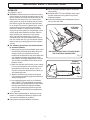
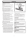
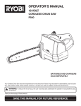
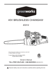
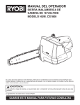
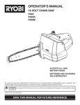
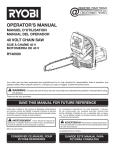
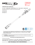
OPERATOR'S MANUAL
18 VOLT CORDLESS CHAIN SAW
MODEL NO. CS1800
Your new cordless chain saw has been engineered and manufactured to Ryobi's high standard for dependability, ease
of operation, and operator safety. When properly cared for, the saw will give you years of rugged, trouble-free
performance.
WARNING:
To reduce the risk of injury, the user must read and understand the operator’s manual before using this product.
Thank you for buying a Ryobi product.
SAVE THIS MANUAL FOR FUTURE REFERENCE
TABLE OF CONTENTS
■
Table of Contents / Introduction ......................................................................................................................... 2
■
Important Safety Instructions ...................................................................................................................... 3 - 7
■
Symbols ....................................................................................................................................................... 8 - 9
■
Specifications .................................................................................................................................................. 10
■
Unpacking ........................................................................................................................................................ 10
■
Applications ..................................................................................................................................................... 10
■
Features .................................................................................................................................................... 10 - 11
■
Glossary of Terms ........................................................................................................................................... 12
■
Operation .................................................................................................................................................. 13 - 22
■
Maintenance ............................................................................................................................................. 23 - 30
■
Bar and Chain Combinations ........................................................................................................................... 31
■
Troubleshooting ............................................................................................................................................... 31
■
Warranty .......................................................................................................................................................... 32
■
Parts Ordering / Service .................................................................................................................................. 34
INTRODUCTION
Cutting wood is an easy task with the 18V chain saw. With the charger and removable battery pack, the chain saw
can be charged and conveniently ready to use. Safety, performance, and dependability have been given top
priority in the design of this chain saw making it easy to maintain and operate.
This saw was designed for occasional light duty use and has some limitations as to what can be cut with it. It was
not designed for felling large trees or sawing of large logs.
Look for this symbol to point out important safety
precautions. It means attention!!! Your safety is involved.
2
IMPORTANT SAFETY INSTRUCTIONS
■ Maintain the unit with care. Keep the cutting edge
sharp and clean for best performance and to
reduce the risk of injury. Follow instructions for
lubricating and changing accessories. Inspect the
battery charger cord periodically, and if damaged,
have it replaced or repaired by an authorized
service dealer.
■ Keep handles dry, clean, and free of oil and grease.
■ Do not operate a chain saw that is damaged,
improperly adjusted, or not completely and securely
assembled. Chain should stop turning when the
trigger is released. If the chain turns after the
trigger has been released, have the unit serviced
by your nearest Ryobi service dealer.
■ Check for damaged parts. Any part or guard that
has been damaged should be carefully checked to
determine that it will operate properly and perform
its intended function. Check for alignment of
moving parts, binding of moving parts, breakage of
parts, mounting, and any other conditions that may
affect its operation. A guard or other part that is
damaged should be properly repaired or replaced
by an authorized service dealer unless otherwise
indicated elsewhere in this manual.
■ All chain saw service, other than the items listed in
the operation and maintenance sections, should be
performed by your nearest Ryobi service dealer.
■ Do not use in the rain, snow or wet conditions.
■ Always maintain a proper stance.
■ Do not adapt your powerhead to a bow guide or
use it to power any attachments or devices not
listed for your saw.
■ Do not cut vines and/or small underbrush.
WARNING:
Do not attempt to operate this unit until you have
read thoroughly and understand completely all
instructions, safety information, etc. contained in
this manual. Failure to comply can result in
accidents involving fire, electric shock, or
serious personal injury.
READ ALL INSTRUCTIONS
BASIC SAFETY PRECAUTIONS
■ Do not operate a chain saw with one hand! Use a
firm grip with thumbs and fingers encircling the
chain saw handles. Serious injury to the operator,
helpers, bystanders, or any combination of these
persons may result from one-handed operation. A
chain saw is intended for two-handed use.
■ Always be aware of what you are doing when using
the chain saw. Use common sense. Do not operate
the chain saw when you are tired, ill, or under the
influence of alcohol, drugs, or medication.
■ Stay alert and pay attention to what you are doing.
Use common sense when using this unit.
■ Keep all parts of your body away from the saw
chain when the unit is running.
■ Always carry the chain saw by the front handle with
the unit stopped and the guide bar and saw chain
positioned to the rear. When transporting your
chain saw, use the appropriate guide bar scabbard.
■ Never let anyone use your chain saw who has not
received adequate instructions in its proper use.
This applies to rentals as well as privately owned
saws.
■ Before you start the unit, make sure the saw chain
is not contacting any object.
■ Stop the chain saw before setting it down. Do not
leave the unit running unattended.
■ To avoid accidental starting, never carry the unit
with your finger on the trigger.
SAFETY APPAREL
■ Wear snug fitting clothing. Always wear heavy, long
pants, overalls, jeans or chaps made of cut resistant material or ones that contain cut resistant
inserts. Wear non-slip safety footwear. Wear nonslip heavy duty gloves to improve your grip and to
protect your hands. Do not wear jewelry, short
pants, sandals, or go barefoot. Do not wear loose
fitting clothing, which could be drawn into the motor
or catch the chain or underbrush. Secure hair so it
is above shoulder level.
■ Wear eye protection which is marked to comply
with ANSI Z87.1 as well as hearing and head
protection when operating this equipment.
3
IMPORTANT SAFETY INSTRUCTIONS
■ Do not cut above shoulder height or overreach
when cutting.
■ Keep the SAFE-T-TIP anti-kickback nose guard
properly mounted on the guide bar to prevent
rotational kickback.
■ Follow the sharpening and maintenance instructions for the saw chain.
KICKBACK
See Figures 1 and 2.
■ WARNING: Kickback may occur when the moving
chain contacts an object at the upper portion of the
tip of the guide bar or when the wood closes in and
pinches the saw chain in the cut. Contact at the
upper portion of the tip of the guide bar can cause
the chain to dig into the object and stop the chain
for an instant. The result is a lightning fast, reverse
reaction which kicks the guide bar up and back
toward the operator. If the saw chain is pinched
along the top of the guide bar, the guide bar can be
driven rapidly back toward the operator. Either of
these reactions can cause loss of saw control
which can result in serious injury. Do not rely
exclusively upon the safety devices built into your
saw. As a chain saw user, you should take several
steps to keep your cutting jobs free from accident
or injury.
■ The following precautions should be followed
to minimize kickback:
1. Always grip the saw firmly with both hands. Hold
the saw firmly with both hands when the unit is
running. Place your right hand on the rear
handle and the left hand on the front handle with
your thumbs and fingers encircling the chain
saw handles. A firm grip together with a stiff left
arm will help you maintain control of the saw if
kickback occurs.
2. Make sure that the area in which you are cutting
is free from obstructions. Do not let the nose of
the guide bar contact a log, branch, fence, or
any other obstruction that could be hit while you
are operating the saw.
3. Always cut with the unit running at full speed.
Fully squeeze the throttle trigger and maintain a
steady cutting speed.
4. Use replacement parts such as low kickback
chain, SAFE-T-TIP anti-kickback nose guards,
chain brakes and special guide bars that reduce
the risks associated with rotational kickback.
Use only the replacement guide bars and low
kickback chains specified by the manufacturer
for your saw.
■ With a basic understanding of kickback, you can
reduce or eliminate the element of surprise. Sudden surprise contributes to accidents.
■ Keep proper footing and balance at all times.
ROTATIONAL
KICKBACK
BAR SHOWN WITHOUT SAFE-T-TIP® NOSE GUARD
FOR ILLUSTRATION PURPOSES ONLY.
Fig. 1
KICKBACK
DANGER ZONE
Fig. 2
4
IMPORTANT SAFETY INSTRUCTIONS
■ Push and Pull - This reaction force is always
opposite to the direction the chain is moving where
wood contact is made. Thus, the operator must be
ready to control the PULL when cutting on the
bottom edge of the bar, and PUSH when cutting
along the top edge. See Figure 3.
IN THE CUTTING/WORK AREA
■ Do not operate a chain saw in a tree, on a ladder,
or scaffold; this is extremely dangerous.
■ Keep ALL children, bystanders, visitors, and
animals out of the work area while starting or
cutting with the chain saw.
NOTE: The size of the work area depends on the
job being performed as well as the size tree or
work piece involved. For example, felling a tree
requires a larger work area than making bucking
cuts.
■ Never start cutting until you have a clear work
area, secure footing, and a planned retreat path
from the falling tree. Cluttered area invite injuries.
■ Do not expose the chain saw to rain.
■ Do not use the chain saw in damp or wet locations.
■ Do not use the chain saw near flammable liquids,
gases, or in any type of explosive atmosphere.
■ Use extreme caution when cutting small size brush
and saplings, because slender material may catch
the saw chain and be whipped toward you or pull
you off balance.
■ When cutting a limb that is under tension, be alert
for spring back so that you will not be struck when
the tension in the wood fibers is released.
■ Do not force the chain saw. The job can be performed better and safer at the rate for which it was
intended.
■ Always use the right product for your application.
The chain saw should be used for cutting wood
only. Never use the chain saw to cut plastic,
masonry or non-wood building materials.
■ Do not use the chain saw for purposes not intended.
■ Store idle chain saw when not in use, chain saw
should be stored in a dry and high or locked area
out of the reach of children. When storing chain
saw, remove battery and place the scabbard on the
bar and chain or store the chain saw in a carry
case.
■ Remove the battery pack from the chain saw
before cleaning, servicing, storing, removing
material from the unit, changing accessories such
as the bar and chain, or when not in use.
PULL
PUSH
5
Fig. 3
IMPORTANT SAFETY INSTRUCTIONS
UNDERSTANDING YOUR CHAIN SAW
SAFETY DEVICES
BATTERY SAFETY
■ Battery operated units do not have to be plugged
into an electrical outlet; therefore, they are always
in operating condition. Be aware of possible hazards even when unit is not operating.
See Figure 4.
SAFE-T-TIP® Anti-Kickback Nose Guard
The SAFE-T-TIP® prevents kickback from happening,
because it covers the tip of the bar where kickback is
generated. Never attempt any kind of cutting where the
SAFE-T-TIP® would have to be removed from the bar
tip.
■ Remove the battery pack from the chain saw before
cleaning, servicing, storing, removing material from
the unit, changing accessories such as the bar and
chain, or when not in use.
■ A battery pack must be recharged only with the
specified charger for the battery pack. A charger
that may be suitable for one type of battery pack
may create a risk of fire when used with another
battery pack. Use battery pack only with charger
listed.
SAFE-T-TIP
BATTERY PACK:
CHARGER:
Fig. 4
Item # 1322401,
1323303, 130224007,
or 130256001
Item # 1423701
■ To reduce the risk of explosion and possible injury,
Do not place battery units or their batteries near fire
or heat.
■ Do not open or mutilate the battery pack. Released
electrolyte is corrosive and may cause damage to
the eyes or skin. It may be toxic if swallowed.
LOW KICKBACK SAW CHAIN
The rakers (depth gauges) ahead of each cutter can
minimize the force of a kickback reaction by preventing
the cutters from digging in too deeply at the kickback
zone. Only use replacement chain that is equivalent to
original chain or has been certified as low kickback
chain per ANSI B175.1.
■ A damaged battery pack is subject to explosion. To
avoid serious personal injury, properly dispose of a
damaged battery pack.
■ Batteries vent hydrogen gas and can explode in the
presence of a source of ignition, such as a pilot
light. To reduce the risk of serious personal injury,
never use any cordless product in the presence of
open flame. An exploded battery pack can propel
debris and chemicals. If exposed, flush with water
immediately.
■ Do not charge unit in a damp or wet location.
Following this rule will reduce the risk of electric
shock.
Low kickback saw chain is chain that has met the
kickback performance requirements of ANSI B175.1 1991 (American National Standard for Power Tools Gasoline-Powered Chain Saws-Safety Requirements)
when tested on the representative sample of chain
saws below 3.8 c.i.d. specified in ANSI B175.1 - 1991.
As saw chains are sharpened during their useful life,
they lose some of the low kickback qualities and extra
caution should be used.
■ For best results, your battery unit should be
charged in a location where the temperature is
more than 50°F (10°C) but less than 100°F (38°C).
Do not store outside or in vehicles.
■ Under extreme usage or temperature conditions,
battery pack leakage may occur. If liquid comes in
contact with your skin, wash immediately with soap
and water, then neutralize with lemon juice or
vinegar. If liquid gets into your eyes, flush them with
clean water for at least 10 minutes, then seek
immediate medical attention.
GUIDE BARS
Generally, guide bars with small radius tips have
somewhat lower kickback potentials.
When making a replacement, be sure to order one of
the Ryobi bars listed for your saw in this operator's
manual. The proper size SAFE-T-TIP® nose guard
comes installed on the bar. Use only guide bars that
have a provision for mounting the SAFE-T-TIP®.
6
IMPORTANT SAFETY INSTRUCTIONS
■ Do not dispose of batteries in a fire. The cell may
explode. Batteries should be recycled, consult your
local waste authority for information regarding
available recycling and/or disposal options.
■ When battery pack is not in use, keep it away from
other metal objects like: paper clips, coins, keys,
nails, screws, or other small metal objects that can
make a connection from one terminal to another.
Shorting the battery pack terminals together may
cause sparks, burns, or a fire.
■
CHARGER SAFETY
■
■ Save these instructions. This manual contains
important Rules for Safe Operation and operating
instructions for charger.
■ Before using battery charger, read all instructions
and cautionary markings in this manual, on battery
charger, and product using battery charger.
■ To reduce risk of injury, charge only nickel-cadmium type rechargeable batteries. Other types of
batteries may burst, causing personal injury and
damage.
■ Do not expose charger to wet or damp conditions.
■ Use of an attachment not recommended or sold by
the battery charger manufacturer may result in a
risk of fire, electric shock, or injury to persons.
■ To reduce risk of damage to charger body and
cord, pull by charger plug rather than cord when
disconnecting charger.
■ Make sure cord is located so that it will not be
stepped on, tripped over, or otherwise subjected to
damage or stress.
■ An extension cord should not be used unless
absolutely necessary. Use of improper extension
cord could result in a risk of fire and electric shock.
If extension cord must be used, make sure:
a. That pins on plug of extension cord are the
same number, size and shape as those of plug
on charger.
■
■
■
■
■
b. That extension cord is properly wired and in
good electrical condition; and
c. That wire size is large enough for AC ampere
rating of charger as specified below:
Cord Length (Feet)
25' 50' 100'
Cord Size (AWG)
16
16
16
NOTE: AWG = American Wire Gage
Do not operate charger with a damaged cord or
plug. If damaged, have replaced immediately by a
qualified serviceman.
Do not operate charger if it has received a sharp
blow, been dropped, or otherwise damaged in any
way; take it to a qualified serviceman.
Do not disassemble charger; take it to a qualified
serviceman when service or repair is required.
Incorrect reassembly may result in a risk of electric
shock or fire.
To reduce risk of electric shock, unplug the
charger from outlet before attempting any maintenance or cleaning. Turning off controls will not
reduce this risk.
Disconnect charger from power supply when not in
use.
Risk of electric shock. Do not touch uninsulated
portion of output connector or uninsulated battery
terminal.
Save these instructions. Refer to them frequently
and use them to instruct others who may use this
unit. If you loan someone this unit, loan them these
instructions also.
SAVE THESE INSTRUCTIONS
7
SYMBOLS
Important: Some of the following symbols may be used on your tool. Please study them and learn their meaning.
Proper interpretation of these symbols will allow you to operate the tool better and safer.
SYMBOL
NAME
EXPLANATION
V
Volts
Voltage
A
Amperes
Current
Hz
Hertz
Frequency (cycles per second)
W
Watt
Power
Minutes
Time
Alternating Current
Type or a characteristic of current
Direct Current
Type or a characteristic of current
No Load Speed
Rotational speed, at no load
Class II Construction
Designates Double Insulated Construction
tools
Revolutions or Reciprocation Per Minute
Revolutions, strokes, surface speed, orbits
etc. per minute
Safety Alert Symbol
Indicates danger, warning or caution. It means
attention!!! Your safety is involved.
Wet Conditions Alert
Do not expose to rain or use in damp
locations.
Read Your Operator’s Manual
Your manual contains special messages to
bring attention to potential safety concerns,
machine damage as well as helpful operating
and servicing information. Please read all the
information carefully to avoid injury and machine damage.
Wear Eye, Hearing, and Head Protection
Wear eye protection which is marked to comply with ANSI Z87.1 as well as hearing and
head protection when operating this equipment.
Wear Safety Footwear
Wear non-slip safety footwear when using this
equipment.
Wear Gloves
Wear non-slip, heavy-duty protective gloves
when handling the pruner.
Keep Children and Pets Away
Danger- Keep children and pets away.
Beware of Kickback
DANGER! Beware of kickback.
min
n0
.../min
8
SYMBOLS
Important: Some of the following symbols may be used on your tool. Please study them and learn their meaning.
Proper interpretation of these symbols will allow you to operate the tool better and safer.
SYMBOL
NAME
EXPLANATION
SAFE-T-TIP
The SAFE-T-TIP® nose guard on your bar
nose prevents rotational kickback.
Bar nose contact
Avoid bar nose contact.
Holding saw
Hold saw properly with both hands.
WARNING:
The operation of any power tool can result in foreign objects being thrown into your
eyes, which can result in severe eye damage. Before beginning tool operation, always
wear safety goggles or safety glasses with side shields and a full face shield when
needed. We recommend Wide Vision Safety Mask for use over eyeglasses or standard
safety glasses with side shields. Always wear eye protection which is marked to comply
with ANSI Z87.1.
The purpose of safety symbols is to attract your attention to possible dangers. The safety symbols, and the
explanations with them, deserve your careful attention and understanding. The safety warnings do not by
themselves eliminate any danger. The instructions or warnings they give are not substitutes for proper accident
prevention measures.
SYMBOL
MEANING
DANGER: Indicates an imminently hazardous situation which, if not avoided, will result in death
or serious injury.
WARNING:
Indicates a potentially hazardous situation which, if not avoided, could result in
death or serious injury.
CAUTION: Indicates a potentially hazardous situation which, if not avoided, may result in minor
or moderate injury. It may also be used to alert against unsafe practices that may cause property
damage.
NOTE:
Advises you of information or instructions vital to the operation or maintenance of the equipment.
SAVE THESE INSTRUCTIONS
NOTE: Save these instructions. Refer to them frequently and use them to instruct others who may use this unit. If
you loan someone this unit, loan them these instructions also.
9
SPECIFICATIONS
PRODUCT SPECIFICATIONS:
Motor
Battery Pack Replacement
Part Number
18 Volt, DC
Bar Length
10 in. (254 mm)
Replacement Bar Part No. 671256002 or 671667002
Charger Rating
Replacement Chain Part No. 6958301 or 690583002
Net Weight
Charger Replacement Part Number
7.5 lbs. (3.4 kg.)
1322401, 1323303,
130224007,
or 130256001
120V, 60 Hz, AC Only
Charger Voltage
18 Volt
Charger Rate
1 Hour
1423701
NOTE: This saw was designed for occasional light duty use and has some limitations as to what can
be cut with it.
UNPACKING
This chain saw has been shipped completely assembled and ready for use. After removing it from the box, inspect
it carefully to make sure no breakage or damage has occurred during shipping. If any parts are damaged or missing,
contact your nearest Ryobi Authorized Service dealer to obtain replacement parts before attempting to operate the
chain saw. The guide bar, chain, wrench, bar and chain oil, scabbard, battery pack, battery charger, and this operator’s
manual are also included.
APPLICATIONS
The chain saw can be used for the following applications only:
■ Limbing and pruning branches from trees.
■ Felling small trees up to 5 in. (127 mm) diameter.
■ Bucking the fallen tree into shorter lengths.
FEATURES
KNOW YOUR CHAIN SAW
WARNING:
See Figure 1.
Before attempting to use the chain saw, familiarize
yourself with all operating features and safety requirements.
If any parts are missing, do not operate your
chain saw until the missing parts are replaced.
Failure to do so could result in possible serious
personal injury.
WARNING:
Carefully read through this entire operator’s
manual before using your chain saw. Pay close
attention to the Important Safety Instructions,
Warnings and Cautions. If you use your chain
saw properly and only for what it is intended, you
will enjoy years of safe, reliable service.
WARNING:
Do not allow familiarity with your chain saw to
make you careless. Remember that a careless
fraction of a second is sufficient to inflict severe
injury.
10
FEATURES
CHAIN OIL TANK CAP
SCABBARD
REAR HANDLE
BAR
SAFE-T-TIP®
CHAIN
BATTERY PACK
HAND GUARD
FRONT HANDLE
TRIGGER LOCK
BUTTON
HEX KEY
STORAGE AREA
HEX KEY
TRIGGER
Fig. 5
11
GLOSSARY OF TERMS
Front Handle
The support handle located at or toward the front of
the chain saw.
Front Handle Guard
A structural barrier between the front handle of a chain
saw and the guide bar, typically located close to the
hand position on the front handle and sometimes
employed as an activating lever for a chain brake.
Guide Bar
A solid railed structure that supports and guides the
saw chain.
Saw Chain
A loop of chain that has cutting teeth for cutting wood.
It is driven by the motor and is supported by the guide
bar.
Kickback
The backward and/or upward motion of the guide bar
occurring when the moving chain contacts an object at
the upper portion of the tip of the guide bar, or when
the wood closes in and pinches the saw chain in the
cut.
Kickback, Pinch
The rapid push back of the saw which can occur when
the wood closed in and pinches the moving saw chain
in the cut along the top of the guide bar.
Kickback, Rotational
The rapid upward and backward motion of the saw
which can occur when the moving saw chain, near the
upper portion of the top of the guide bar, contacts an
object such as a log or branch.
Low-Kickback Chain
A chain that complies with the kickback performance
requirements of ANSI B175-1-1991 when tested on a
representative sample of chain saws.
Normal Cutting Position
Those positions assumed in performing the bucking
and felling cuts.
Notching Undercut
A notch cut in a tree that directs the tree’s fall.
Felling
The process of cutting down a tree.
Felling Back Cut
The final cut in a tree felling operation, made on the
opposite side of the tree from the notching undercut.
Oiler Control
A system for oiling the guide bar and saw chain.
Rear Handle
The support handle located at or toward the rear of the
saw.
Reduced Kickback Guide Bar
A guide bar which has been demonstrated to reduce
kickback significantly.
Replacement Saw Chain
A chain that complies with the kickback performance
requirements of ANSI B175.1-1991 when tested with
specific chain saws. It may not meet the ANSI performance requirements when used with other saws.
Switch
A device that when operated will complete or interrupt
an electrical power circuit to the motor of the chain
saw.
Switch Lockout
A movable stop that prevents the unintentional operation of the switch until manually actuated.
Safe-T-Tip
An attachment that may be provided on the end of the
guide bar to prevent the chain, on the end of the guide
bar, from contacting the wood.
Drive Sprocket or Sprocket
The toothed part that drives the saw chain.
12
OPERATION
BATTERY PACK AND CHARGER
BATTERY
PACK
LED FUNCTION OF CHARGER
See Figure 6.
LED WILL BE ON TO INDICATE STATUS OF
CHARGER AND BATTERY PACK:
■ Red LED on = Fast charging mode.
■ Green LED on = Fully charged battery pack.
■ Yellow and Green LEDs on = Control charge or
defective battery pack.
■ No LED on = Defective charger or battery pack.
BATTERY
CHARGER
CHARGING YOUR CHAIN SAW
The battery pack for your chain saw has been shipped
in a low charge condition to prevent possible problems.
Therefore, you should charge it prior to use.
NOTE: Batteries will not reach full charge the first time
they are charged. Allow several cycles (pruning
followed by recharging) for them to fully charge.
TO CHARGE
■ Charge battery pack only with the charger provided.
■ Make sure power supply is normal household
voltage, 120 volts, 60 Hz, AC only.
■ Connect charger to power supply.
■ Place battery pack in charger. See Figure 3. Align
raised rib on battery pack with groove in charger.
■ Press down on battery pack to be sure contacts on
battery pack engage properly with contacts in
charger. When properly connected, red light will
turn on.
■ Normally, the yellow and green lights on the
charger will come on. This indicates charger is in
control charge mode and should switch to fast
charge mode within 5 minutes. When charger is in
fast charge mode the red light will come on. If after
a period of 15 minutes the yellow and green lights
remain on, remove the battery pack, wait 1 minute
and reinsert battery pack in charger. If the yellow
and green lights continue to remain on an additional 15 minutes, the battery pack is damaged and
will not accept charge.
■ When your battery pack becomes fully charged,
the red light will turn off and the green light will turn
on.
■ After normal usage, 1 hour of charge time is
required to be fully charged. A minimum charge
time of 1 to 1-1/2 hours is required to recharge a
completely discharged tool.
RED LIGHT
YELLOW
LIGHT
■
■
■
GREEN
LIGHT
RED LIGHT “ON” INDICATES FAST CHARGING
MODE
YELLOW AND GREEN LIGHTS “ON” INDICATES
CONTROL CHARGE OR POSSIBLE FAULTY
BATTERY
GREEN LIGHT “ON” INDICATES FULLY CHARGED
Fig. 6
■ The battery pack will become slightly warm to the
touch while charging. This is normal and does not
indicate a problem.
■ DO NOT place charger in an area of extreme heat
or cold. It will work best at temperatures above
50°F and below 100°F.
IMPORTANT INFORMATION FOR RECHARGING
HOT BATTERIES
When using your chain saw continuously, the batteries
in your battery pack will become hot. You should let a
hot battery pack cool down for approximately 30
minutes before attempting to recharge.
NOTE: This situation only occurs when continuous use
of your chain saw causes the batteries to become hot.
It does not occur under normal circumstances. Refer
to “Charging Your Chain saw” earlier in this manual, for
normal recharging of batteries. If the charger/charging
assembly does not charge your battery pack under
normal circumstances, return both the battery pack
and charger/charging assembly to your nearest Ryobi
Authorized Service dealer for electrical check.
13
OPERATION
TO INSTALL BATTERY PACK
See Figure 7.
1. Place the battery pack in your chain saw. Align
raised rib on battery pack with groove in chain
saw’s battery port.
2. Make sure the latches on each side of the battery
pack snap in place and that battery pack is secured
in chain saw before beginning operation.
CAUTION:
Remove battery pack from unit. Fill oil tank with
Homelite Bar and Chain Oil before starting the
chain saw. Failure to lubricate the chain will
cause damage to the bar and chain.
CHAIN OIL SYSTEM
TO REMOVE BATTERY PACK
See Figure 7.
Locate latches on side of battery pack and depress
both sides to release the battery pack from the chain
saw.
See Figure 8.
1. Use Homelite Bar and Chain Oil. It is formulated to
perform over a wide temperature range with no
dilution required.
NOTE: Do not use dirty, used or otherwise contaminated oils. Damage may occur to the bar or chain.
2. Carefully pour the bar and chain oil into the tank.
3. Check and fill the oil tank when battery is recharged, or as needed.
4. Depress the oil tank cap several times to pump the
oil to the chain before starting the saw.
5. Depress the oil tank cap every 20-30 seconds while
cutting to keep the chain lubricated.
NOTE: It is normal for oil to seep from the saw when
not in use. To prevent seepage, empty the oil tank after
each use. When storing the unit for a long period of
time (three months or longer) be sure the chain is
lightly lubricated; this will prevent rust on the chain and
bar sprocket.
CAUTION:
When placing battery pack in your chain saw, be
sure raised rib on battery pack aligns with
groove in chain saw's battery port and latches
snap in place properly. Improper assembly of
battery pack can cause damage to internal
components.
BATTERY
PORT
BATTERY
PACK
LATCHES
Fig. 7
Fig. 8
14
OPERATION
STARTING AND STOPPING THE CHAIN
SAW
See Figure 9.
WARNING:
Keep body to the left of the chain line. Never
straddle the saw or chain, or lean over past the
chain line.
STARTING THE CHAIN SAW
1. Place the chain saw on a flat bare surface and
make sure no objects or obstructions are in immediate vicinity which could come in contact with the
bar and chain.
2. Press and hold the trigger lock button. This makes
the trigger operational.
3. Press and hold the trigger, release the trigger lock
button and continue to squeeze the trigger for
continued operation.
TRIGGER LOCK
BUTTON
TRIGGER
TRIGGER LOCK
BUTTON
STOPPING THE CHAIN SAW
1. Release the trigger to stop the chain saw.
2. Upon release of the trigger, the trigger lock button
will be automatically reset to the lock position.
This cordless chain saw is not designed for cutting
trees larger than 5 in. (127 mm) in diameter.
This cordless chain saw is designed for limbing and
pruning type cutting, as well as cutting trees up to 5 in.
(127 mm) in diameter only.
Do not attempt to make any cut that would require
removal of the SAFE-T-TIP.
TRIGGER
Fig. 9
PREPARATION FOR CUTTING
PROPER GRIP ON HANDLES
Figures 10, 11, and 12.
Refer to “Important Safety Instructions” earlier in this
manual for appropriate safety equipment.
1. Wear non-slip gloves for maximum grip and protection.
2. Hold the saw firmly with both hands. Always keep
your left hand on the front handle and your right
hand on the rear handle so that your body is to the
left of the chain line.
Fig. 10
15
OPERATION
WARNING:
Never use a left-handed (cross-handed) grip, or
any stance which would place your body or arm
across the chain line.
3. Maintain a proper grip on the saw whenever the
unit is running. The fingers should encircle the
handle and the thumb is wrapped under the handlebar. This grip is least likely to be broken (by a
kickback or other sudden reaction of the saw). Any
grip in which the thumb and fingers are on the
same side of the handle, is dangerous because a
slight kick of the saw can cause loss of control.
CHAIN LINE
Fig. 12
WARNING:
Do not operate the throttle trigger with your left
hand and hold the front handle with your right
hand. Never allow any part of your body to be in
the chain line while operating a saw.
PROPER GRIP
IMPROPER
GRIP
Fig. 11
16
OPERATION
PROPER CUTTING STANCE
See Figure 13.
■ Weight should be balanced with both feet on solid
ground.
■ Keep left arm with elbow locked in a "straight arm"
position to withstand any kickback force.
■ Your body should always be to the left of the chain
line.
■ Thumb should be on underside of handlebar.
CHAIN LINE
STRAIGHT ARM
POSITION
BASIC CUTTING PROCEDURE
Practice cutting a few small logs using the following
technique to get the "feel" of using your saw before
you begin a major sawing operation.
1. Take the proper stance in front of the wood with the
saw off.
2. Squeeze the trigger and let the chain accelerate to
full speed before entering the cut.
3. Begin cutting with the saw against the log.
4. Keep the unit running the entire time you are
cutting, maintain a steady speed.
5. Allow the chain to cut for you; exert only light
downward pressure. If you force the cut, damage to
the bar, chain, or unit can result.
6. Release the trigger as soon as the cut is completed, allowing the chain to stop. If you run the
saw without a cutting load, unnecessary wear can
occur to the chain, bar, and unit.
7. Do not put pressure on the saw at the end of the
cut.
Fig. 13
■ Always cut with both feet on solid ground to prevent
being pulled off balance.
■ Do not cut above chest height, as a saw held
higher is difficult to control against kickback forces.
■ Do not fell trees near electrical wires or buildings.
Leave this operation for professionals.
■ Cut only when visibility and light are adequate for
you to see clearly.
TREE FELLING
Unusual Hazardous Tree Felling Conditions
Do not fell trees during periods of high wind or heavy
precipitation. Wait to do your cutting until the hazard
has ended.
WORK AREA PRECAUTIONS
■ Cut only wood or materials made from wood; no
sheet metal, no plastics, no masonry, no non-wood
building materials.
■ Never allow children to operate your saw. Allow no
person to use this chain saw who has not read this
Operator's Manual or received adequate instructions for the safe and proper use of this chain saw.
■ When felling a tree, keep everyone - helpers,
bystanders, children, and animals a safe distance
from the cutting area. During felling operations, the
safe distance should be a least twice the height of
the largest trees in the felling area. During bucking
operations, keep a minimum distance of 15 feet
(4.5 m) between workers.Trees should not be felled
in a manner that would endanger any person, strike
any utility line or cause any property damage. If the
tree does make contact with any utility line, the
utility company should be notified immediately.
WARNING:
Do not cut down trees having an extreme lean or
large trees that have rotten limbs, loose bark, or
hollow trunks. Have these trees pushed or
dragged down with heavy equipment, then cut
them up.
WARNING:
Do not cut trees near electrical wires or
buildings.
WARNING:
Check the tree for damaged or dead branches
that could fall and hit you during felling.
17
OPERATION
WARNING:
PLANNED LINE OF FALL
Periodically glance at the top of the tree during
the backcut to assure the tree is going to fall in
the desired direction.
WARNING:
If the tree starts to fall in the wrong direction, or
if the saw gets caught or hung up during the fall,
leave the saw and save yourself!
90°
■ Felling a tree - When bucking and felling operations
are being performed by two or more persons, at the
same time, the felling operation should be separated from the bucking operation by a distance of
at least twice the height of the tree being felled.
Trees should not be felled in a manner that would
endanger any person, strike any utility line or cause
any property damage. If the tree does make
contact with any utility line, the utility company
should be notified immediately.
■ Before any cuts are started, pick your escape route
(or routes in case the intended route is blocked);
clear the immediate area around the tree and make
sure there are no obstructions in your planned path
of retreat. Clear path of safe retreat approximately
135° from planned line of fall. The retreat path
should extend back and diagonally to the rear of the
expected line of fall. See Figure 14.
■ Before felling is started consider the force and
direction of the wind, the lean and balance of the
tree, and the location of large limbs. These things
influence the direction in which the tree will fall. Do
not try to fell a tree along a line different from its
natural line of fall.
■ The chain saw operator should keep on the uphill
side of the terrain as the tree is likely to roll or slide
downhill after it is felled.
■ Remove dirt, stones, loose bark, nails, staples, and
wire from the tree where felling cuts are to be
made.
■ Notched Undercut. Cut a notch about 1/3 the
diameter of the tree, perpendicular to the direction
of fall. Make the cuts of the notch so they intersect
at a right angle to the line of fall. This notch should
be cleaned out to leave a straight line. To keep the
weight of the wood off the saw, always make the
lower cut of the notch before the upper cut. See
Figure 15.
SAFE
RETREAT
ZONE
PLANNED PATH OF SAFE RETREAT
135° FROM PLANNED LINE OF FALL
SAFE
RETREAT
ZONE
135°
PLANNED
LINE OF FALL
45°
90 °
45°
135°
SAFE
RETREAT
ZONE
Fig. 14
HINGE
2 IN. (5 CM) OR 1/10 DIA
NOTCH APPROX. 1/3
DIAMETER OF
TRUNK
BACK CUT
2 IN. (5 CM)
18
Fig. 15
OPERATION
■ Felling Backcut. The backcut is always made
level and horizontal, and at a minimum of 2 inches
(5 cm) above the horizontal cut of the notch. See
Figures 15 and 16.
■ Never cut through to the notch. Always leave a
band of wood between the notch and backcut
(approximately 2 inches (5 cm) or 1/10 the diameter
of the tree). This is called "hinge" or “hingewood.”
It controls the fall of the tree and prevents slipping
or twisting or shoot-back of the tree off the stump.
See Figures 15 and 16.
■ On large diameter trees, stop the back cut before it
is deep enough for the tree to either fall or settle
back on the stump. Then insert soft wooden or
plastic wedges into the cut so they do not touch the
chain. The wedges can be driven in, little by little, to
help jack the tree over. See Figure 17.
NOTE: When bucking or felling with a wedge, it
may be necessary to remove the SAFE-T-TIP®
anti-kickback device to allow the bar to be drawn
through the cut. After the cut is complete, the tip
should be reinstalled immediately.
■ As tree starts to fall, stop the chain saw and put it
down immediately. Retreat along the cleared path,
but watch the action in case something falls your
way. Be alert for overhead limbs or branches that
may fall and watch your footing.
WEDGE
BUCKING
See Figures 18 through 21.
Bucking is the term used for cutting a fallen tree to the
desired log length.
■ Always make sure your footing is secure and your
weight is distributed evenly on both feet.
■ Cut only one log at a time.
■ Support small logs on a saw horse or another log
while bucking.
■ Keep a clear cutting area. Make sure that no objects
can contact the guide bar nose and chain during
cutting, this can cause kickback. To avoid the danger, keep the SAFE-T-TIP® anti-kickback device
attached while cutting. Refer to “Precautions Against
Kickback” earlier in this manual.
WARNING:
Never cut through to the notch when making a
backcut. The hinge controls the fall of the tree,
this is the section of wood between the notch
and backcut.
KICKBACK
Fig. 18
NOTCH
BACK CUT
HINGE
Fig. 17
Fig. 16
19
OPERATION
■
■
When bucking on a slope, always stand on the uphill
side of the log. To maintain complete control of the
chain saw when cutting through the log, release the
cutting pressure near the end of the cut without
relaxing your grip on the chain saw handles. Do not
let the chain contact the ground. After completing the
cut, wait for the saw chain to stop before your move
the chain saw. Always stop the motor before moving
from tree to tree. See Figure 19.
Sometimes it is impossible to avoid pinching (with
just standard cutting techniques) or difficult to predict
which way a log will settle when cut. To avoid
pinching while cutting, rotate or move the log so that
the pinch is eliminated.
BUCKING LOGS UNDER STRESS
See Figures 20 and 21.
When the log is supported along its entire length, it
should be cut from the top or overbucking.
When the log is supported on one end, cut 1/3 the
diameter from the underside or underbucking. Then
make the finishing cut by overbucking to meet the first
cut.
As the log is being cut, it will tend to bend. The saw
can become pinched or hung in the log if you make the
first cut deeper than 1/3 of the diameter of the log.
Give special attention to logs under stress to prevent
the bar and chain from pinching.
When bucking on a slope, always stand on the uphill
side of the log as shown in Figure 19. When “cutting
through”, to maintain complete control of the chain
saw, release the cutting pressure near the end of the
cut without relaxing your grip on the chain saw
handles. Do not let the chain contact the ground. After
completing the cut, wait for the saw chain to stop
before your move the chain saw. Always stop the
motor before moving from tree to tree. See Figure 19.
LOG SUPPORTED AT ONE END:
LOAD
FINISHING CUT
Fig. 19
1ST CUT
1/3 DIA
LOG SUPPORTED AT BOTH ENDS:
LOAD
1ST CUT 1/3 DIA
FINISHING CUT
20
Fig. 20
OPERATION
TYPES OF CUTTING USED
WARNING:
See Figure 21.
Never climb into a tree to limb or prune. Do not
stand on ladders, platforms, a log or in any
position which can cause you to lose your
balance or control of the saw.
OVERBUCKING
Begin on the top side of the log with the bottom of the
saw against the log; exert light pressure downward.
Note that the saw will tend to pull away from you.
UNDERBUCKING
Begin on the under side of the log with the top of the
saw against the log; exert light pressure upward.
During underbucking, the saw will tend to push back at
you. Be prepared for this reaction and hold the saw
firmly to maintain control.
LIMBING
See Figure 22.
Limbing is removing branches from a fallen tree.
■ Work slowly, keeping both hands on the chain saw
with a firm grip. Always make sure your footing is
secure and your weight is distributed evenly on
both feet.
■ Leave the larger support limbs under the tree to
keep the tree off the ground while cutting.
■ Limbs should be cut one at a time. Remove the cut
limbs from the work area often to help keep the
work area clean and safe.
■ Branches under tension should be cut from the
bottom up to avoid binding the chain saw.
■ Keep the tree between you and the chain saw while
limbing. Cut from the side of the tree opposite the
branch you are cutting.
OVERBUCKING
UNDERBUCKING
1
2
3
4
CUT LIMBS ONE AT A TIME AND LEAVE SUPPORT
LIMBS UNDER TREE UNTIL LOG IS CUT
Fig. 22
Fig. 21
21
OPERATION
PRUNING
See Figure 23.
Pruning is trimming limbs from a live tree.
■ Work slowly, keeping both hands on the chain saw
with a firm grip. Always make sure your footing is
secure and your weight is distributed evenly on
both feet.
■ Do not cut from a ladder, this is extremely dangerous. Leave this operation for professionals.
■ Do not cut above chest height as a saw held higher
is difficult to control against kickback.
■ When pruning trees it is important not to make the
finishing cut next to the main limb or trunk until you
have cut off the limb further out to reduce the
weight. This prevents stripping the bark from the
main member.
1. Underbuck the branch 1/3 through for your first
cut.
2. Your second cut should overbuck to drop the
branch off.
3. Now make your finishing cut smoothly and
neatly against the main member so the bark will
grow back to seal the wound.
LOAD
SECOND CUT
FIRST CUT
1/3 DIAMETER
FINISHING CUT
Fig. 23
SPRINGPOLE
WARNING:
Fig. 24
If the limbs to be pruned are above chest height,
hire a professional to perform the pruning.
SPRINGPOLES
WARNING:
See Figure 24.
A springpole is any log, branch, rooted stump, or
sapling which is bent under tension by other wood so
that it springs back if the wood holding it is cut or
removed. On a fallen tree, a rooted stump has a high
potential of springing back to the upright position
during the bucking cut to separate the log from the
stump. Watch out for springpoles, they are dangerous.
Springpoles are dangerous and could strike the
operator, causing the operator to lose control of
the chain saw. This could result in severe or
fatal injury to the operator.
22
MAINTENANCE
ASSEMBLING BAR AND CHAIN
See Figures 25, 26, 27, 28 and 29.
ADJUSTING
PIN
SPROCKET
CAUTION:
Remove the battery pack from the chain saw and
make sure the chain has stopped before you do
any work on the saw.
BAR
WARNING:
WASHER
The safety instructions in this section are to
protect the user from serious personal injury.
CHAIN
CAUTION:
CHAIN TENSION
PIN HOLE
Always wear gloves when handling the bar and
chain; these components are sharp and may
contain burrs.
CHAIN
COVER
CHAIN
COVER
SCREW
Fig. 25
WARNING:
Never touch or adjust the chain while the motor
is running. The saw chain is very sharp, always
wear protective gloves when performing
maintenance to the chain.
1. Remove the battery pack before you do any work
on the chain saw.
2. Remove the hex key from the storage area and use
it to remove the chain cover screw, washer and
chain cover from the chain saw.
3. Remove the bar and chain from the mounting
surface.
4. Remove the old chain from the bar.
5. Lay out the new saw chain in a loop and straighten
any kinks. The cutters should face in the direction
of chain rotation. If they face the opposite direction,
turn the loop over.
6. Place the chain drive links into the bar groove.
Position the chain so there is a loop at the back of
the bar. Hold the chain in position on the bar and
place the loop around the sprocket of the chain
saw. Fit the bar flush against the mounting surface
so that the bar stud is in the long slot of the bar.
NOTE: When placing the bar on the bar stud,
assure that the adjusting pin is in the chain tension
pin hole.
CHAIN DRIVE
LINKS
BAR
GROOVE
23
Fig. 26
MAINTENANCE
7. Replace the chain cover, washer and chain cover
screw. Tighten the chain cover screw finger tight
only. The bar must be free to move for tension
adjustment.
8. Remove all the slack from the chain by turning the
chain tensioning screw clockwise until the chain
seats snugly against the bar with the drive links in
the bar groove.
9. Lift the tip of the guide bar up to check for sag.
Release the tip of the guide bar and turn the chain
tensioning screw 1/2 turn clockwise. Repeat this
process until sag does not exist.
10. Hold the tip of the guide bar up and tighten the bar
mounting screw securely.
11. Chain is correctly tensioned when there is no sag
on the underside of the guide bar, the chain is
snug, but it can be turned by hand without binding.
NOTE: If chain is too tight, it will not rotate.
Loosen the chain cover screw slightly and turn
tension adjuster 1/4 turn counterclockwise. Lift the
tip of the guide bar up and retighten chain cover
screw securely. Assure that the chain will rotate
without binding.
12. Place the hex key back into the storage area.
LIFT THE TIP OF
THE GUIDE BAR
UP TO CHECK
FOR SAG
Fig. 28
HEX KEY
Fig. 29
CHAIN
TENSIONING
SCREW
Fig. 27
24
MAINTENANCE
CHAIN TENSION
See Figures 30 and 31.
1. Stop the engine before setting the chain tension.
Make sure the guide bar screw is loosened to finger
tight, turn the chain tensioner clockwise to tension
the chain. Refer to “Assembling the Bar and Chain”
earlier in this manual for additional information.
A cold chain is correctly tensioned when there is no
slack on the underside of the guide bar, the chain is
snug, but it can be turned by hand without binding.
2. Chain must be re-tensioned whenever the flats on
the drive links hang out of the bar groove.
3. During normal saw operation, the temperature of
the chain will increase. The drive links of a correctly
tensioned warm chain will hang approximately
.050 in. (1.25 mm) out of the bar groove.
NOTE: New chain tends to stretch, check chain
tension frequently and tension as required.
APPROX. .050 (1.25 mm)
CAUTION:
Chain tensioned while warm, may be too tight
upon cooling. Check the “cold tension” before
next use.
FLATS
Fig. 30
25
Fig. 31
MAINTENANCE
CHAIN MAINTENANCE
See Figures 32 and 33.
CUTTING
CORNER
TOP PLATE
CAUTION:
Remove the battery pack and make sure the
chain has stopped before you do any work on the
saw.
SIDE PLATE
DEPTH GAUGE
RIVET HOLE
HEEL
Use only low-kickback chain on this saw. This fastcutting chain will provide kickback reduction when
properly maintained.
For smooth and fast cutting, chain needs to be maintained properly. The chain requires sharpening when
the wood chips are small and powdery, the chain must
be forced through the wood during cutting, or the chain
cuts to one side. During maintenance of your chain,
consider the following:
■ Improper filing angle of the side plate can increase
the risk of a severe kickback.
■ Raker (depth gauge) clearance.
■ Too low increases the potential for kickback.
■ Not low enough decreases cutting ability.
■ If cutter teeth have hit hard objects such as nails
and stones, or have been abraded by mud or sand
on the wood, have service dealer sharpen chain.
NOTE: Inspect the drive sprocket for wear or damage
when replacing the chain. If signs of wear or damage
are present in the areas indicated, have the drive
sprocket replaced by a Ryobi Service dealer.
TOE
GULLET
Fig. 32
CHECK FOR WEAR OR
DAMAGE
Fig. 33
HOW TO SHARPEN THE CUTTERS
See Figure 34 and 35.
Be careful to file all cutters to the specified angles and
to the same length, as fast cutting can be obtained
only when all cutters are uniform.
1. Wear gloves for protection. Properly tension the
chain prior to sharpening. Refer to “Chain Tension
Section” earlier in this manual. Do all of your filing
at the mid-point of the bar.
2. Use A 5/32 in. diameter round file and holder.
3. Keep the file level with the top plate of the tooth. Do
not let the file dip or rock.
4. Using light but firm pressure, stroke towards the
front corner of the tooth.
Lift file away from the steel on each return stroke.
Fig. 34
26
MAINTENANCE
5. Put a few firm strokes on every tooth. File all left
hand cutters in one direction. Then move to the
other side and file the right hand cutters in the
opposite direction. Occasionally remove filings from
the file with a wire brush.
LEFT HAND
CUTTERS
WARNING:
Improper chain sharpening increases the
potential of kickback.
RIGHT HAND
CUTTERS
Fig. 35
WARNING:
Failure to replace or repair damaged chain can
cause serious injury.
CORRECT TOP PLATE
FILING ANGLE
WARNING:
30 °
INCORRECT TOP PLATE
FILING ANGLE
LESS
THAN 30°
MORE
THAN 30°
The saw chain is very sharp, always wear
protective gloves when performing maintenance
to the chain.
Fig. 36
TOP PLATE FILING ANGLE
See Figure 36.
■ CORRECT 30° - File holders are marked with guide
marks to align file properly to produce correct top
plate angle.
■ LESS THAN 30° - For Cross Cutting.
■ MORE THAN 30° - Feathered Edge Dulls Quickly.
CORRECT SIDE
PLATE FILING
ANGLE
INCORRECT SIDE PLATE
FILING ANGLE
HOOK
SIDE PLATE ANGLE
See Figure 37.
■ CORRECT- 80o Produced automatically if correct
diameter file is used in file holder.
■ HOOK- “Grabs” and dulls quickly. Increases
potential of KICKBACK.
Results from using a file with diameter too small, or
file held too low.
■ BACKWARD SLOPE- Needs too much feed
pressure, causes excessive wear to bar and chain.
Results from using a file with diameter too large, or
file held too high.
BACKWARD
SLOPE
80°
Fig. 37
RAKER CLEARANCE
.025 in. (0.6 mm)
DEPTH GAUGE CLEARANCE
See Figure 38.
1. The depth gauge should be maintained at a clearance of .025 in. (0.6 mm). Use a depth gauge tool for
checking the depth gauge clearances.
2. Every time the chain is filed, check the depth gauge
clearance.
Fig. 38
27
MAINTENANCE
Use a Flat File and a Depth Gauge Jointer to lower all
gauges uniformly. Depth gauge jointers are available in
.020 in. to .035 in. (0.5 mm to 0.9 mm). Use a .025 in.
(0.6 mm) depth gauge jointer. After lowering each
depth gauge, restore original shape by rounding the
front. Be careful not to damage adjoining drive links
with the edge of the file. See Figures 39 and 40.
Depth gauges must be adjusted with the flat file in the
same direction the adjoining cutter was filed with the
round file. Use care not to contact cutter face with flat
file when adjusting depth gauges.
DEPTH GAUGE JOINTER
FLAT FILE
Fig. 39
GUIDE BAR MAINTENANCE
See Figure 41.
When the guide bar shows signs of wear, reverse it
on the saw to distribute the wear for maximum bar
life. The bar should be cleaned every day of use and
checked for wear and damage.
Feathering or burring of the bar rails is a normal
process of bar wear. Such faults should be smoothed
with a file as soon as they occur.
A bar with any of the following faults should be replaced.
■ Wear inside the bar rails which permits the chain to
lay over sideways.
■ Bent guide bar.
■ Cracked or broken rails.
■ Spread rails.
In addition, guide bars with a sprocket at their tip must
be lubricated weekly with a grease syringe to extend
the guide bar life. Using a grease syringe, lubricate
weekly in the lubricating hole. See Figure x.
Turn the guide bar and check that the lubrication holes
and chain groove are free from impurities.
RESTORE ORIGINAL
SHAPE BY ROUNDING
THE FRONT
Fig. 40
LUBRICATING HOLE
Fig. 41
REVERSING THE GUIDE BAR
See Figures 41, 42, and 43.
1. Remove the SAFE-T-TIP® mounting screw.
2. Remove the SAFE-T-TIP® from the bar.
3. Remove the chain from the bar and turn the bar
over.
NOTE: Bottom of bar should not be on top.
4. Replace the chain on the bar. Refer to “Assembling
the Bar and Chain” earlier in this manual for specific information.
5. Replace the SAFE-T-TIP® on the bar nose.
NOTE: The locking tab fits in the recessed hole in
the bar.
6. Tighten the screw with your finger.
7. From the finger-tight position, tighten the screw an
additional 3/4 of a turn using a wrench.
28
MAINTENANCE
MOUNTING SCREW
CAUTION:
Remove the battery pack and make sure the
chain has stopped before you do any work on
the saw.
LOCKING RIVET
WARNING:
Although the guide bar comes with a SAFE-TTIP® anti-kickback device already installed, you
need to check the tightness of the mounting
screw before each use.
SAFE-T-TIP
SAFE-T-TIP® NOSE GUARD MAINTENANCE
Fig. 42
See Figures 42 and 43.
Tighten the mounting screw of the nose guard as
instructed below. These are specially hardened
screws. If the screw cannot be installed tightly, replace
both the screw and the SAFE-T-TIP® before further
operation. Do not replace with an ordinary screw.
In addition to preventing chain contact with solid
objects at the nose of the bar, the SAFE-T-TIP® also
helps keep the chain away from abrasive surfaces
such as the ground. Keep it on the right hand side of
the bar, where it will be between the chain and the
ground during flush with ground cutting.
The mounting screw requires a 5/16 in. wrench (or
adjustable wrench) to achieve the recommended
tightness of 35 to 45 in. lb. (4-5 Nm). A tightness
within this range can be achieved by the following
method.
1. Tighten the screw with your finger.
2. From the finger-tight position, tighten the screw an
additional 3/4 of a turn using a wrench.
TIGHTEN 3/4
OF A TURN
Fig. 43
WARNING:
When servicing use only identical Ryobi
replacement parts. Use of any other parts may
create a hazard or cause product damage.
MOUNTING SAFE-T-TIP® NOSE GUARD
See Figuress 42 and 43.
1 Mount the SAFE-T-TIP® on the bar nose.
NOTE: The tab fits in the recessed hole in the bar.
2. Tighten the screw with your finger.
3. From the finger-tight position, tighten the screw an
additional 3/4 of a turn using a wrench.
Avoid using solvents when cleaning plastic parts. Most
plastics are susceptible to damage from various types
of commercial solvents and may be damaged by their
use. Use clean cloths to remove dirt, dust, oil, grease,
etc.
WARNING:
Do not at any time let brake fluids, gasoline,
petroleum-based products, penetrating oils, etc.
come in contact with plastic parts. They contain
chemicals that can damage, weaken or destroy
plastic.
29
MAINTENANCE
BATTERIES
WARNING:
The battery pack for your chain saw is equipped with
nickel-cadmium rechargeable batteries. Length of
service from each charging will depend on the type of
work you are doing.
The batteries in this tool have been designed to
provide maximum trouble free life. However, like all
batteries, they will eventually wear out. Do not disassemble battery pack and attempt to replace the
batteries. Handling of these batteries, especially when
wearing rings and jewelry, could result in a serious
burn.
To obtain the longest possible battery life, we suggest
the following:
■ Store and charge your batteries in a location where
the temperature is above 50°F but less than 100°F.
■ Never store batteries in a discharged condition.
Recharge them immediately after they are discharged.
■ All batteries gradually lose their charge. The higher
the temperature the quicker they lose their charge.
If you store your chain saw for long periods of time
without using it, recharge it every month or two.
This practice will prolong battery life.
Do not attempt to modify this tool or create
accessories not recommended for use with this
tool. Any such alteration or modification is
misuse and could result in a hazardous condition
leading to possible serious personal injury.
WARNING:
Any repairs requiring disassembly should only be
performed by a Ryobi Authorized Service dealer.
For the repair center nearest you, call 1-800525-2579.
TRANSPORTING AND STORING
See Figure 44.
■ Do not store or transport the chain saw when it is
running. The chain saw should always be idle
before storing or transporting.
■ Always place the guide bar scabbard on the bar
and chain before storing or transporting the chain
saw. Use caution to avoid the sharp teeth of the
chain.
■ Clean the chain saw thoroughly before storing.
Store the chain saw indoors, in a dry place that is
locked and/or inaccessible to children.
■ Keep away from corrosive agents such as garden
chemicals and de-icing salts.
DISPOSAL OF THE EXHAUSTED BATTERY
To preserve natural resources,
please recycle or dispose of properly. This product contains a nickelcadmium battery. Must be disposed
of properly. Local, state, or federal
laws may prohibit disposal of NickelCadmium batteries in ordinary trash.
Consult your local waste authority for
information regarding available recycling and/or disposal options. For more information on
battery recycling call 1-800-8BATTERY.
BATTERY PACK PREPARATION FOR RECYCLING
WARNING:
Upon removal, cover the battery pack’s terminals
with heavy duty adhesive tape. Do not attempt to
destroy or disassemble battery pack or remove
any of its components. Also, never touch both
terminals with metal objects and/or body parts as
short circuit may result. Keep away from
children. Failure to comply with these warnings
could result in fire and/or serious injury.
Fig. 44
30
BAR AND CHAIN COMBINATIONS
RECOMMENDED BAR AND CHAIN COMBINATIONS
Bar Part Number - 10 in. (254 mm)
Chain Part Number
671256002 or 671667002
6958301 or 690583002
TROUBLESHOOTING
IF THESE SOLUTIONS DO NOT SOLVE THE PROBLEM CONTACT YOUR AUTHORIZED SERVICE DEALER.
PROBLEM
POSSIBLE CAUSE
SOLUTION
Bar and chain running
hot and smoking.
1. Check chain tension for
over tight condition
2. Chain oil tank empty.
Motor runs, but chain is
not rotating.
1. Chain tension too tight.
2. Check guide bar and chain
assembly.
3. Check guide bar and chain
for damage.
31
1. Tension chain. Refer to “Chain Tension”
earlier in this manual.
2. Check oil tank.
1. Retension chain, Refer to “Chain Tension”
earlier in this manual.
2. Refer to “Assembling the Bar and Chain”
earlier in this manual.
3. Inspect guide bar and chain for damage.
NOTES
32
NOTES
33
OPERATOR'S MANUAL
18 Volt Cordless Chain Saw
Model No. CS1800
CUSTOMER SERVICE INFORMATION
For parts or service, contact your nearest Ryobi authorized service center. Be sure to provide all relevant
information when you call or visit. For the location of the authorized service center nearest you, please call
1-800-525-2579 or visit us online at www.ryobitools.com.
The model number of this tool is found on a plate attached to the buffer/polisher. Please record the serial
number in the space provided below. When ordering repair parts, always give the following information:
Model No.
CS1800
Serial No.
RYOBI TECHNOLOGIES INC.
1428 Pearman Dairy Road
Anderson, SC 29625
Post Office Box 1207
Anderson, SC 29622
www.ryobitools.com
1-800-525-2579
983000-353
10-04