1
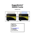
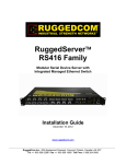
RuggedSwitch RSG2288 ® 9-Port Modular Managed Gigabit Ethernet Switch Installation Guide February 15, 2011 www.ruggedcom.com RuggedCom Inc. I 300 Applewood Crescent, Concord, Ontario, Canada L4K 5C7 Tel: +1 905 856 5288 I Fax: +1 905 856 1995 I Toll Free: 1 888 264 0006 Copyright COPYRIGHT © 2010 RuggedCom Inc. ALL RIGHTS RESERVED Dissemination or reproduction of this document, or evaluation and communication of its contents, is not authorized except where expressly permitted. Violations are liable for damages. All rights reserved, particularly for the purposes of patent application or trademark registration. This document contains proprietary information, which is protected by copyright. All rights are reserved. No part of this document may be photocopied, reproduced or translated to another language without the prior written consent of RuggedCom Inc. Disclaimer of liability We have checked the contents of this manual against the hardware and software described. However, deviations from the description cannot be completely ruled out. RuggedCom shall not be liable for any errors or omissions contained herein or for consequential damages in connection with the furnishing, performance, or use of this material. The information given in this document is reviewed regularly and any necessary corrections will be included in subsequent editions. We appreciate any suggested improvements. We reserve the right to make technical improvements without notice. Registered Trademarks RuggedRated™, ROS™ and eRSTP™ are trademarks of RuggedCom Inc. RuggedRouter® and RuggedSwitch® are registered trademarks of RuggedCom Inc. Other designations in this manual might be trademarks whose use by third parties for their own purposes would infringe the rights of the owner. Contacting RuggedCom Corporate Headquarters US Headquarters Europe Headquarters RuggedCom Inc. 300 Applewood Crescent Concord, Ontario Canada, L4K 5C7 RuggedCom 1930 Harrison St., Suite 209 Hollywood, Florida USA, 33020 RuggedCom Unit 41, Aztec Centre, Aztec West, Almondsbury, Bristol United Kingdom BS32 4TD Tel: +1 905 856 5288 Fax: +1 905 856 1995 Toll-free: 1 888 264 0006 Tel: +1 954 922 7938 ext. 103 Fax: +1 954 922 7984 Toll-free: 1 888 264 0006 Tel: Fax: +44 1454 203 404 +44 1454 203 403 Email: [email protected] Technical Support Toll Free (North America): 1 866 922 7975 International: +1 905 856 5288 Email: [email protected] Web: www.RuggedCom.com RuggedCom® 2 RuggedSwitch® RSG2288 Installation Guide rev103 Federal Communications Commission Radio Frequency Interference Statement This equipment has been tested and found to comply with the limits for a Class A digital device pursuant to Part 15 of the FCC Rules. These limits are designed to provide reasonable protection against harmful interference when the equipment is operated in a commercial environment. This equipment generates, uses and can radiate radio frequency energy and, if not installed and used in accordance with the instruction manual, may cause harmful interference to radio communications. Operation of this equipment in a residential area is likely to cause harmful interference in which case the user will be required to correct the interference on his own expense. CAUTION This product contains a laser system and is classified as a “CLASS 1 LASER PRODUCT” Use of controls or adjustments or performance of procedures other than those specified herein may result in hazardous radiation exposure. This product contains no user-serviceable parts. Attempted service by unauthorized personnel shall render all warranties null and void. Changes or modifications not expressly approved by RuggedCom Inc. could invalidate specifications, test results, and agency approvals, and void the user’s authority to operate the equipment. Should this device require service, please refer to the “Warranty” section of this guide. IMPORTANT This product should be installed in a restricted access location where access can only be gained by service personnel or users who have been instructed about the reasons for the restrictions applied to the location and about any precautions that shall be taken; and access is through the use of a tool or lock and key, or other means of security, and is controlled by the authority responsible for the location. RuggedCom® 3 RuggedSwitch® RSG2288 Installation Guide rev103 Table of Contents Table of Contents Table of Contents.............................................................................................................. 4 Table of Figures ................................................................................................................ 6 Table of Tables ................................................................................................................. 7 1 Product Overview ...................................................................................................... 8 1.1 Functional Overview.......................................................................................... 8 1.2 Feature Highlights ............................................................................................. 8 1.3 Mounting Flexibility.......................................................................................... 11 1.4 Ethernet Panel Description.............................................................................. 12 1.4.1 Fiber Optic Transceiver Orientation and Connection .............................. 13 1.5 Display Panel Description ............................................................................... 15 2 Installation ............................................................................................................... 17 2.1 Rack Mounting ................................................................................................ 17 2.2 Panel and DIN Rail Mounting .......................................................................... 18 2.3 Power Supply Wiring and Grounding .............................................................. 19 2.3.1 AC Power Supply Wiring Examples (RSG2288) ..................................... 21 2.3.2 DC Power Supply Wiring Examples ........................................................ 22 2.3.3 Dual Power Supplies – DC and AC Inputs .............................................. 23 2.4 Dielectric Strength (HIPOT) Testing ................................................................ 24 2.5 Failsafe Alarm Relay Wiring and Specifications .............................................. 25 2.6 Console Port Wiring ........................................................................................ 26 2.7 Ethernet Ports ................................................................................................. 27 2.7.1 RJ45 Twisted-Pair Data Ports ................................................................. 27 2.7.2 Gigabit Ethernet 1000Base-TX Cabling Recommendations ................... 27 2.7.3 Transient Suppression............................................................................. 28 2.8 Pluggable optics – Installation, removal, and precautions .............................. 28 2.8.1 Module Insertion – GBICs and SFPs....................................................... 29 2.8.2 GBIC Module Removal............................................................................ 30 2.8.3 SFP Module Removal.............................................................................. 30 2.9 Precision Time Protocol (PTP) Card and IEEE1588 v2 .................................. 31 2.9.1 PTP Card Panel Description.................................................................... 32 2.9.2 GPS Antenna Installation ........................................................................ 32 2.9.3 IRIG-B Outputs ........................................................................................ 34 3 Technical Specifications.......................................................................................... 36 3.1 Power Supply Specifications ........................................................................... 36 3.2 Failsafe Relay Specifications .......................................................................... 36 3.3 Networking Standards Supported ................................................................... 36 3.4 Copper Ethernet Port Specifications ............................................................... 37 3.5 Fiber Ethernet Optic Specifications ................................................................. 37 3.5.1 Fast Ethernet (100Mbps) Optical Specifications ..................................... 37 3.5.2 Gigabit Ethernet (1000Mbps) Optical Specifications ............................... 38 3.6 PTP Card Specifications ................................................................................. 39 3.6.1 IRIG-B Outputs ........................................................................................ 39 3.7 Operating Environment ................................................................................... 39 3.8 Mechanical Specifications ............................................................................... 40 4 Type Tests .............................................................................................................. 41 4.1 IEC 61850-3 Type Tests ................................................................................. 41 4.2 IEEE 1613 Type Tests .................................................................................... 42 RuggedCom® 4 RuggedSwitch® RSG2288 Installation Guide rev103 Table of Contents 5 6 4.3 IEC Environmental Type Tests........................................................................ 42 Agency Approvals ................................................................................................... 43 Warranty.................................................................................................................. 43 RuggedCom® 5 RuggedSwitch® RSG2288 Installation Guide rev103 Table of Figures Table of Figures Figure 1: RSG2288 Rack mount chassis orientation options – Front and rear mount.... 11 Figure 2: RSG2288 Ethernet Port Layout ....................................................................... 12 Figure 3: Ethernet panel LEDs........................................................................................ 12 Figure 4: 1000LX SFP (mini-GBIC) Module and LC connector ...................................... 13 Figure 5: 1000LX GBIC connector .................................................................................. 13 Figure 6: 1000LX LC connector ...................................................................................... 14 Figure 7: 1000LX SC connector...................................................................................... 14 Figure 8: 1000LX ST connector ...................................................................................... 14 Figure 9: 100FX MTRJ connector ................................................................................... 14 Figure 10: RSG2288 LED Display Panel ........................................................................ 15 Figure 11: RS2000 Family 19” Rack Mount Adapters..................................................... 17 Figure 12: Rack mount adapter mounting location ......................................................... 17 Figure 13: RSG2200 PANEL/DIN RAIL mounting diagram ............................................ 18 Figure 14: RS2000 Series Philips Screw Terminal Block ............................................... 19 Figure 15: RS2000 Series Phoenix Plug Terminal Block................................................ 19 Figure 16: Chassis Ground Connection .......................................................................... 20 Figure 17: AC Single Power Supply Wiring Example...................................................... 21 Figure 18: AC Dual Redundant Power Supply Wiring Example...................................... 21 Figure 19: DC Power Supply Wiring Examples............................................................... 22 Figure 20: DC and AC Power Supply Wiring Examples.................................................. 23 Figure 21: Dielectric Strength (HIPOT) Testing .............................................................. 24 Figure 22: Failsafe Alarm Relay Wiring........................................................................... 25 Figure 23: Console port on display board ....................................................................... 26 Figure 24 : RS2000 Series Console cable ...................................................................... 26 Figure 25 : RJ45 port pin configuration. .......................................................................... 27 Figure 26: SFP Orientation for top row and bottom row ports......................................... 29 Figure 27: Locking latch location on GBIC optical modules............................................ 30 Figure 28: SFP Bail Latch location.................................................................................. 30 Figure 29: SFP Removal................................................................................................. 30 Figure 30: PTP Card Panel Description .......................................................................... 32 Figure 31: IRIG-B Simplified Schematic.......................................................................... 35 Figure 32: RSG2288 Mechanical Dimensions ................................................................ 40 RuggedCom® 6 RuggedSwitch® RSG2288 Installation Guide rev103 Table of Tables Table of Tables Table 1: Pluggable Fiber Transceiver Modules............................................................... 13 Table 2: Fixed Fiber Transceivers................................................................................... 14 Table 3: LED Display – Device status LED behavior definition....................................... 15 Table 4: Port Status behavior definition .......................................................................... 16 Table 5: RS2000 Series Power terminal block connection description........................... 20 Table 6: RS232 over RJ45 console cable pin-out........................................................... 26 Table 7: RJ45 Ethernet pin assignment .......................................................................... 27 Table 8: Cabling categories and 1000BaseTx compliance defined. ............................... 28 Table 9: RSG2888 Time Synchronization Sources......................................................... 31 Table 10: RSG2288 Time Synchronization Services ...................................................... 31 Table 11: PTP Card Connectors ..................................................................................... 32 Table 12: PTP Card LED Functions................................................................................ 32 Table 13: GPS Antenna Specifications ........................................................................... 33 Table 14: Coaxial Cable Delay........................................................................................ 34 Table 15: IRIG-B PWM Output Specifications ................................................................ 39 Table 16: IRIG-B AM Output Specifications.................................................................... 39 Table 17 - IEC 61850-3 Type Tests ................................................................................ 41 Table 18 - IEEE 1613 Type Tests ................................................................................... 42 Table 19 - Environmental Type Tests ............................................................................. 42 RuggedCom® 7 RuggedSwitch® RSG2288 Installation Guide rev103 Product Overview 1 Product Overview 1.1 Functional Overview The RuggedSwitch® RSG2288 is an industrially hardened, fully managed, modular, Ethernet switch specifically designed to operate reliably in electrically harsh and climatically demanding utility substation and industrial environments. The RSG2288 includes the IEEE 1588 v2 protocol with hardware time stamping allowing high precision time synchronization over the Ethernet network with accuracies of 1us or better. The RSG2288’s superior ruggedized hardware design coupled with the embedded Rugged Operating System (ROSTM) provides improved system reliability and advanced cyber security and networking features, making it ideal for creating mission-critical, Gigabit networks or aggregating switches into a Gigabit backbone. The RSG2288’s modular flexibility offers 100/1000BaseX fiber and 10/100/1000BaseTX copper port combinations. Support for front or rear mount connectors coupled with support for multiple fiber connector types (SFP, GBIC, LC, SC) without loss of port density makes the RSG2288 highly versatile and suitable for any application. The RSG2288 is packaged in a rugged, galvanized steel enclosure with industrial grade DIN, panel, or 19” rack-mount mounting options. 1.2 Feature Highlights Ethernet Ports Up to 9-Gigabit Ethernet ports supporting copper and fiber media Up to 9 100FX Fiber Fast Ethernet ports 2 port modules for tremendous flexibility Fiber types supported include multimode, singlemode, and bidirectional single strand Full compliance with IEEE: 802.3, 802.3u & 802.3z Non-blocking, store and forward switching Full duplex operation and flow control (IEEE 802.3x) Industry standard fiber optical connectors: LC, SC, SFP, GBIC Long haul optics allow Gigabit distances up to 70km Advanced Time Synchronization Support for IEEE 1588 v2, GPS, and IRIG-B time synchronization Hardware time stamping on all ports including Gigabit Transparent clock operation for high precision on switched networks (1us or better) Peer-to-peer path delay measurements High precision TCXO (Temperature Compensated Oscillator) Supports master, slave and transparent clock modes Support for IRIG-B input and output RuggedCom® 8 RuggedSwitch® RSG2288 Installation Guide rev103 Product Overview Cyber Security Features Multi-level user passwords SSH/SSL encryption MAC-based port security Selective port enable/disable Port-based network access control using IEEE 802.1x VLAN support (IEEE 802.1Q) to segregate and secure network traffic RADIUS centralized access management SNMPv3 featuring encrypted authentication and session RuggedRated™ for Reliability in Harsh Environments Immunity to EMI and heavy electrical surges o Zero-Packet-Loss™ Technology o Meets IEEE 1613 Class 2 (electric utility substations) o Exceeds IEC 61850-3 (electric utility substations) o Exceeds IEEE 61800-3 (variable speed drive systems) o Exceeds IEC 61000-6-2 (generic industrial environment) o Exceeds NEMA TS-2 (traffic control equipment) -40 to +85°C operating temperature (no fans) Conformal coated printed circuit boards (optional) 18 AWG galvanized steel enclosure Hazardous Location Certification: Class 1 Division 2 Universal Power Supply Options Fully integrated, dual-redundant (optional) power supplies Universal high-voltage range: 88-300VDC or 85-264VAC Popular low voltage DC ranges: 12, 24 or 48 VDC Screw or pluggable terminal blocks for reliable, connections CSA/UL 60950 safety approved to +85°C maintenance-free Rugged Operating System (ROS™) Networking Features Simple plug and play operation: automatic learning, negotiation, and crossover detection RSTP (Rapid Spanning Tree Protocol) support: IEEE 802.1w eRSTP™ (Enhanced Rapid Spanning Tree) support, <5ms network fault recovery QoS (Quality of Service) support: IEEE 802.1p, for real-time traffic VLAN (Virtual LAN) support: IEEE 802.1Q with double tagging GVRP (GARP VLAN Registration Protocol) support: IEEE 802.1D GMRP (GARP Multicast Registration Protocol) support: IEEE 802.1D Link Aggregation support: IEEE 802.3ad IGMP Snooping for multicast filtering Port rate limiting and broadcast storm limiting RuggedCom® 9 RuggedSwitch® RSG2288 Installation Guide rev103 Product Overview Port configuration, status, statistics, mirroring, security Loss of link management on fiber ports SNTP time synchronization (both client and server) Industrial automation features (e.g. Modbus) Rugged Operating System (ROS™) Management Features Secure Web-based management interface Console menu and Command Line management interfaces via SSH, RSH, and Telnet SNMP v1, v2c, and v3 RMON (Remote MONitoring) Rich set of diagnostics with logging and alarms RuggedCom® 10 RuggedSwitch® RSG2288 Installation Guide rev103 Product Overview 1.3 Mounting Flexibility The RS2000 series of products have been designed with maximum mounting and display flexibility. Customers can order an RS2000 series switch that can be mounted in a standard 19” rack, 1” DIN Rail, or directly onto a panel. For rack mount installations, the RS2000 series can be ordered with connectors on the front panel or on the rear of the chassis. Placing the connectors on the rear allows all data and power cabling to be installed and connected at the rear of the rack. See Figure 1 for rack-mount orientation examples. Figure 1: RSG2288 Rack mount chassis orientation options – Front and rear mount. RuggedCom® 11 RuggedSwitch® RSG2288 Installation Guide rev103 Product Overview 1.4 Ethernet Panel Description The Ethernet connector panel of the RSG2288 is organized into six slots, five of which are modular and may be selected at the time the unit is ordered. Figure 2 shows the physical layout of these ports. Figure 2: RSG2288 Ethernet Port Layout Slots 1, 2, 3 and 4 support two-port Ethernet modules up to 1Gbps. Slot 5 supports a one-port module up to 1Gbps. Slot 6 contains the PTP Source Card (refer to 2.9 for details) to support advanced time synchronization. Section 3.5 lists and provides specifications for the fiber optic interfaces available for the RSG2200 series. The complement of modules installed on a particular unit may be determined by reading the factory data file via the RuggedSwitch® ROSTM user interface. Each Ethernet port is equipped with an LED per port that indicates link/activity status information. The LED is solid for ports with a valid link, and blinks for activity. Figure 3 shows a copper port module in slot 1 and a fiber module in slot 2 along with the associated link/activity LEDs for each port. Figure 3: Ethernet panel LEDs RuggedCom® 12 RuggedSwitch® RSG2288 Installation Guide rev103 Product Overview 1.4.1 Fiber Optic Transceiver Orientation and Connection Depending on the order code of the product, the RSG2200 series products can be equipped with several different types of fiber optic ports. The Transmit (TX) and Receive (RX) connections of each port must be properly connected and matched for proper link and operation. Modules populated on the top row of the device typically have locking mechanisms or tabs facing the top of the unit. Modules located on the bottom row of the device have locking mechanisms or tabs facing the bottom of the unit. The diagrams in this section depict each fiber connector style supported by the RuggedSwitch® in order to provide a reference for the proper orientation of cable connections. A front view (looking into the connector) and a top view of the connector module are shown for each one. Note that if modules are populated on the bottom row of the device, the transceiver orientation will be inverted relative to the diagram (i.e. RX and TX will be reversed). Figure 4 and Figure 5 show front and top views of the pluggable fiber transceiver modules supported by RuggedSwitch®. Note that when the module is installed in the unit, most of the body of the module as shown in top views below will not be visible. Table 1: Pluggable Fiber Transceiver Modules Figure 4: 1000LX SFP (mini-GBIC) Module and LC connector RuggedCom® Figure 5: 1000LX GBIC connector 13 RuggedSwitch® RSG2288 Installation Guide rev103 Product Overview Figure 6 through Figure 9 show front and top views of the fixed fiber transceiver modules supported by RuggedSwitch®. Note that when the daughter card containing transceiver modules is installed in the unit, most of the body of the module as shown in top views below will not be visible. Table 2: Fixed Fiber Transceivers Figure 6: 1000LX LC connector Figure 8: 1000LX ST connector RuggedCom® Figure 7: 1000LX SC connector Figure 9: 100FX MTRJ connector 14 RuggedSwitch® RSG2288 Installation Guide rev103 Product Overview 1.5 Display Panel Description RuggedCom RS2000 series products are equipped with a versatile display panel, shown in Figure 10, which is designed to provide quick status information for each port, as well as the entire device to allow for simple diagnostics and troubleshooting. It features: RS232 console port for ‘out of band’ console access and configuration Power supply and Alarm status indicators Convenient port status indicators conveying Link/Activity, Duplex, or Speed via the Mode push-button (toggles between the three display modes) System reset via the Mode push-button (if held for 5 seconds) Figure 10: RSG2288 LED Display Panel The device status LEDs provide a quick visual indication of the operational status of the unit. Table 3 lists the possible LED colors and the corresponding description. LED PS1 / PS2 Color Green Red Off Red Alarm Off Description Power supply operating normal Power supply failure No power supply installed An alarm condition exists – log in to the web management interface or to the CLI to determine the alarm code No alarms exist Table 3: LED Display – Device status LED behavior definition RuggedCom® 15 RuggedSwitch® RSG2288 Installation Guide rev103 Product Overview The port-based LEDs can be cycled between three display modes: Status, Duplex, and Speed. Pushing the mode button causes the display mode to be cycled. Mode Status Duplex Speed Color Green (Solid) Green (Blinking) Off Green (Solid) Orange (Solid) Off Green (Blinking) Green (Solid) Orange (Solid) Off Description Link detected Activity No link Full-Duplex operation Half-Duplex operation No link 1000Mb/s 100Mb/s 10Mb/s No link Table 4: Port Status behavior definition RuggedCom® 16 RuggedSwitch® RSG2288 Installation Guide rev103 Installation 2 Installation 2.1 Rack Mounting The RS2000 family of products can be rack mounted using the included rack mount adapter assemblies shown in Figure 11. Secure the rack mount adapter to the front side of the chassis using the included black PAN head Philips screws in the positions shown in Figure 13. The entire chassis can then be mounted to a standard 19” rack. An additional two rack mount adapters are included to optionally secure the rear of the chassis in high-vibration or seismically active locations. Figure 11: RS2000 Family 19” Rack Mount Adapters Figure 12: Rack mount adapter mounting location Note: Since heat within the RSG2288 is channeled to the enclosure, it is recommended that 1 rack-unit of space (1.75”) be kept unpopulated and free of equipment above each RS2000 series product to allow for a small amount of convectional airflow. Although forced airflow is not necessary, any increase in airflow will result in a reduction of ambient temperature that will improve long-term reliability of all equipment mounted within the rack space. RuggedCom® 17 RuggedSwitch® RSG2288 Installation Guide rev103 Installation 2.2 Panel and DIN Rail Mounting RS2000 series products can be ordered as a Panel/DIN mount chassis. Both options involve the use of the panel/DIN adapters to be mounted on each side of the chassis enclosure. The adapter allows for the chassis to be mounted on the standard 1” DIN rail using the grooves in the adapter, secured using the included Philips screw. See Figure 13 for a PANEL/DIN mount diagram. Figure 13: RSG2200 PANEL/DIN RAIL mounting diagram RuggedCom® 18 RuggedSwitch® RSG2288 Installation Guide rev103 Installation 2.3 Power Supply Wiring and Grounding RS2000 series products support dual redundant power supplies – “Power Supply 1 (PS1)” and “Power Supply 2 (PS2)”. The connections for PS1, PS2 and the failsafe relay are located on the terminal block as shown in Figure 14 and Figure 15. RSG2200 series products can be equipped with either a Philips Screw Terminal Block or a Phoenix Plug Terminal Block. The Philips Screw Terminal Block has Philips screws with a compression plate allowing either bare wire connections or crimped, terminal lugs. We recommend the use of #6 size ring lugs to ensure secure, reliable connections under severe shock or vibration. Both terminal blocks have a safety cover which must be removed via two Phillips screws before connecting any wires. The safety cover must be re-attached after wiring to ensure personnel safety. Refer to Table 5 below for a description of each terminal as well as sections 2.3.1 through 2.3.3 for wiring examples. Figure 14: RS2000 Series Philips Screw Terminal Block Philips Screw Terminal with Cover Safety Cover Philips Screw Terminal without Cover Safety Cover Chassis Ground Screws Connection Phoenix Plug Terminal with Cover Safety Cover Screws Surge / Chassis Ground Jumper Phoenix Plug Terminal without Cover Chassis Ground Surge / Chassis Ground Jumper Connection Figure 15: RS2000 Series Phoenix Plug Terminal Block Safety Cover RuggedCom® Terminal Terminal 19 RuggedSwitch® RSG2288 Installation Guide rev103 Installation The RS2000 Family chassis ground connection, shown in Figure 16, uses a #632 screw. It is recommended to terminate the ground connection in a #6 ring lug, and to use a torque setting not exceeding 15 in.lbs (1.7 Nm). #6-32 screw with ext. washer. #6 ring lug stainless steel standoff Figure 16: Chassis Ground Connection Terminal Number Description Usage PS1 Live / + is connected to the positive (+) terminal if the power source is DC or to the (Live) terminal if the power source is AC. PS1 Surge Ground is connected to the Chassis Ground via a jumper on the terminal block. Surge Ground is used as the ground conductor for all surge and transient 2 PS1 Surge Ground suppression circuitry. NOTE: Surge Ground must be disconnected from Chassis Ground during HIPOT (dielectric strength) testing. PS1 Neutral / - is connected to the negative (-) terminal if 3 PS1 Neutral / the power source is DC or to the (Neutral) terminal if the power source is AC. Chassis Ground is connected to the Safety Ground terminal for AC inputs or the equipment ground bus for DC 4 Chassis Ground inputs. Chassis ground connects to both power supply surge grounds via a removable jumper. PS2 Live / + is connected to the positive (+) terminal if the 5 PS2 Live / + power source is DC or to the (Live) terminal if the power source is AC. PS2 Surge Ground is connected to the Chassis Ground via a jumper on the terminal block. Surge Ground is used as the ground conductor for all surge and transient 6 PS2 Surge Ground suppression circuitry. NOTE: Surge Ground must be disconnected from Chassis Ground during HIPOT (dielectric strength) testing. PS2 Neutral / - is connected to the negative (-) terminal if 7 PS2 Neutral / the power source is DC or to the (Neutral) terminal if the power source is AC. 8 Relay NO Contact Normally open, failsafe relay contact. 9 Relay Common Failsafe relay common contact. 10 Relay NC Contact Normally closed, failsafe relay contact. Table 5: RS2000 Series Power terminal block connection description 1 RuggedCom® PS1 Live / + 20 RuggedSwitch® RSG2288 Installation Guide rev103 Installation 2.3.1 AC Power Supply Wiring Examples (RSG2288) Figure 17: AC Single Power Supply Wiring Example Figure 18: AC Dual Redundant Power Supply Wiring Example Notes: 100-240VAC rated equipment: A 250VAC appropriately rated circuit breaker must be installed. Equipment must be installed according to the applicable country wiring codes. When equipped with two HI voltage power supplies, independent AC sources can be used to power the product for greater redundancy. RuggedCom® 21 RuggedSwitch® RSG2288 Installation Guide rev103 Installation 2.3.2 DC Power Supply Wiring Examples Figure 19: DC Power Supply Wiring Examples Notes: 125/250VDC rated equipment: A 300VDC appropriately rated circuit breaker must be installed. A circuit breaker is not required for 12, 24 or 48 VDC rated power supplies. For dual DC power supplies, Separate circuit breakers must be installed and separately identified. Equipment must be installed according to the applicable country wiring codes. RuggedCom® 22 RuggedSwitch® RSG2288 Installation Guide rev103 Installation 2.3.3 Dual Power Supplies – DC and AC Inputs Figure 20: DC and AC Power Supply Wiring Examples Notes: 125/250VDC rated equipment: A 300VDC appropriately rated circuit breaker must be installed. 100-240VAC rated equipment: A 250VAC appropriately rated circuit breaker must be installed. A circuit breaker is not required for 12, 24 or 48 VDC rated power supplies. Separate circuit breakers must be installed and separately identified. Equipment must be installed according to the applicable country wiring codes. RuggedCom® 23 RuggedSwitch® RSG2288 Installation Guide rev103 Installation 2.4 Dielectric Strength (HIPOT) Testing For dielectric strength (HIPOT) testing in the field, users must remove the metal jumper located on terminal 2, 4, and 6 of the power supply terminal block. This metal jumper connects transient suppression circuitry to chassis ground and must be removed in order to avoid damage to transient suppression circuitry during HIPOT testing. Figure 21 shows the proper HIPOT test connections and should be followed to avoid damage to the device. Figure 21: Dielectric Strength (HIPOT) Testing RuggedCom® 24 RuggedSwitch® RSG2288 Installation Guide rev103 Installation 2.5 Failsafe Alarm Relay Wiring and Specifications The “Failsafe” output relay is provided to signal critical error conditions that may occur on RS2000 series products. The contacts are energized upon power-up of the unit and remain energized unless a critical error occurs. The proper relay connections are shown in Figure 22. Control of the output is user-selectable and can be programmed via the Rugged Operating System (ROS®). One common application for this output is to signal an alarm if a power failure or removal of control power occurs. Figure 22: Failsafe Alarm Relay Wiring RuggedCom® 25 RuggedSwitch® RSG2288 Installation Guide rev103 Installation 2.6 Console Port Wiring A RS232 console port for configuration and management of the device is located on the LED display module shown in Figure 23. This port is intended to be a temporary connection during initial configuration or troubleshooting and allows for direct serial access to the management console. The connection is made using the DB9-Female to RJ45 console cable included in the device packaging shown in Figure 24. Console connection settings are: 57600 baud, no parity bits, 8 data bits, and 1 stop bit. Figure 23: Console port on display board Figure 24 : RS2000 Series Console cable For user reference, the console cable pin-out is show in Table 6. RuggedCom RS232 over RJ45 pin-out specification Signal Name (PC is DTE) DCD – Carrier detect RxD – Receive data (to DTE) TxD – Transmit data (from DTE) DTR – Data terminal ready GND – Signal GND DSR – Data set ready RTS – Ready to send CTS – Clear to send RI – Ring Indicator DB9- Female 1 2 3 4 5 6 7 8 9 RJ45 Male 2 5 6 3 4 1* 8 7 1* Table 6: RS232 over RJ45 console cable pin-out After initial configuration, the RSG2288 can be configured via a number of new mechanisms such as Telnet SSH, and the built-in web server. Consult the ROS™ User Guide for further details. Note: This port is not intended to be a permanent connection. Serial cable must not exceed 2m (6.5 ft) in length. RuggedCom® 26 RuggedSwitch® RSG2288 Installation Guide rev103 Installation 2.7 Ethernet Ports 2.7.1 RJ45 Twisted-Pair Data Ports RSG2288 Ethernet switches are equipped with up to nine 10/100/1000BaseTX ports that allow connection to standard CAT-5 UTP cable with RJ45 male connectors. All RS2000 series RJ45 RuggedSwitch products feature autonegotiation, auto-polarity, and auto-crossover functions. The RJ45 receptacles can also accept and take advantage of screened (commonly known as “shielded”) cabling. Figure 25 shows the RJ45 port pins configuration. Pin 8 Pin 1 Figure 25 : RJ45 port pin configuration. 10/100BaseTx Pin-out Pin 1 2 3 6 4, 5, 7, 9 Description RX + RX TX + TX NC Table 7: RJ45 Ethernet pin assignment 2.7.2 Gigabit Ethernet 1000Base-TX Cabling Recommendations The IEEE 802.3ab Gigabit Ethernet standard defines 1000 Mbit/s Ethernet communications over distances of up to 100 meters using 4 pairs of category 5 (or higher) balanced, unshielded twisted-pair cabling. For wiring guidelines, system designers and integrators should refer to the Telecommunications Industry Association (TIA) TIA/EIA-568-A wiring standard that characterizes minimum cabling performance specifications required for proper Gigabit Ethernet operation. To ensure reliable, error-free data communications, new and preexisting communication paths should be verified for TIA/EIA-568-A compliance. Table 8 summarizes the relevant cabling standards. RuggedCom® 27 RuggedSwitch® RSG2288 Installation Guide rev103 Installation Cabling Category <5 5 5e 6 >6 1000BaseTx Required action Compliant New wire infrastructure required No Yes Verify TIA/EIA-568-A compliance No action required. New installations should be designed Yes with Category 5e components or higher Yes No action required Connector and cabling standards to be determined. Yes Table 8: Cabling categories and 1000BaseTx compliance defined. Follow these recommendations for copper data cabling in high electrical noise environments: Data cable lengths should be as short as possible - ideally limited to 3m (10ft) in length. Copper data cables should not be used for inter-building communications. Power and data cables should not be run in parallel for long distances, and ideally should be installed in separate conduits. Power and data cables should intersect at 90 angles when necessary to reduce inductive coupling. Shielded/screened cabling can optionally be used. The cable shield should be grounded at one single point to avoid the generation of ground loops. 2.7.3 Transient Suppression RuggedCom does not recommend the use of copper cabling of any length for critical, real-time, substation automation applications. However, transient suppression circuitry is present on all copper ports to protect against damage from electrical transients and to ensure IEC 61850-3 and IEEE 1613 Class 1 conformance. This means that during the transient event, communications errors or interruptions may occur but recovery is automatic. RuggedCom also does not recommend using these ports to interface to field devices across distances which could produce high levels of ground potential rise, (i.e. greater than 2500V) during line-to-ground fault conditions. 2.8 Pluggable optics – Installation, removal, and precautions The RSG2200 series of products can be ordered with pluggable optic form factors: SFP (Small Form-factor Pluggable) or GBIC (Gigabit Interface Converter). SFP and GBIC modules can be safely inserted and removed while the chassis is powered and operating – this feature is also known as “hotswappable”. When inserting or removing optics, there are several precautions that should be taken. They include: Ensuring that dust caps are mounted on SFP cages at all times unless a user is in the process of inserting or removing an SFP module. The dust caps will RuggedCom® 28 RuggedSwitch® RSG2288 Installation Guide rev103 Installation prevent the accumulation of residue or particles that may inhibit proper operation. Ensuring that the user has properly discharged any possible electrostatic build-up in order to prevent electrostatic discharges (ESD). This can be accomplished by proper user ‘grounding’ via an ESD wrist strap, or by touching earth or chassis ground before performing installation or removal of optics. ESD can damage or shorten the life of optical modules when not plugged into a chassis. Ensuring that SFP and GBIC optical modules are always stored in an ESDsafe bag or other suitable ESD-safe environment, free from moisture and stored at the proper temperature (–40 to +85C). Disconnecting all cables from the SFP or GBIC module prior to insertion or removal of the module. Using only optics certified by RuggedCom Inc. with RuggedCom products. Damage can occur to optics and product if compatibility and reliability have not been properly assessed. 2.8.1 Module Insertion – GBICs and SFPs Special attention must be paid to the orientation of SFP and GBIC modules upon installation in the RuggedSwitch® chassis. For example, Figure 26 shows the proper orientation of SFP modules installed to both upper and lower slots. Modules on the upper row must be inserted top-side up, and modules on the lower row must be inserted top-side down. SFP modules should be inserted with the bail-latch in the locked position. Figure 26: SFP Orientation for top row and bottom row ports Both SFP and GBIC modules should gently slide into their ports and should lock in place when fully inserted. Dust covers should be in place when installing the modules, and should always be in place when cables are not connected. Diagrams of both SFP and GBIC modules are provided in Table 1 as a guide to the orientation of each type. RuggedCom® 29 RuggedSwitch® RSG2288 Installation Guide rev103 Installation 2.8.2 GBIC Module Removal GBIC Modules have two locking latches, one on either side of the module, as shown in Figure 27. To remove a GBIC module, disconnect any cables and replace the dust cover to protect the optics. Depress both latches simultaneously and gently pull the module from the chassis. The module should be immediately stored in an ESD-safe environment. Figure 27: Locking latch location on GBIC optical modules 2.8.3 SFP Module Removal SFP Modules are removed using the metal bail latch located on the top of the module as shown in Figure 28. To remove the SFP module, disconnect any cables and replace the dust cover to protect the optics. Grasp the bail latch and gently pull outwards to unlock and remove the module. Removal of an SFP module is shown further in Figure 29. The module should be immediately stored in an ESD-safe environment. Figure 28: SFP Bail Latch location RuggedCom® Figure 29: SFP Removal 30 RuggedSwitch® RSG2288 Installation Guide rev103 Installation 2.9 Precision Time Protocol (PTP) Card and IEEE1588 v2 The Precision Time Protocol (PTP) card option for the RSG2288 adds the ability to provide time synchronization via IRIG-B, and to synchronize to an external IRIG-B source or to the GPS network. The time synchronization capabilities of the RSG2288, both with and without the PTP card option, are summarized below: NTP Without PTP Card With PTP Card IEEE 1588 v2 Synchronization Source IRIG-B PWM GPS Table 9: RSG2888 Time Synchronization Sources NTP Without PTP Card With PTP Card IEEE 1588 v2 Synchronization Service IRIG-B AM IRIG-B PWM Table 10: RSG2288 Time Synchronization Services NTP (Network Time Protocol) is the standard for synchronizing the clocks of computer systems throughout the Internet and is suitable for systems that require accuracies in the order of 1 ms. IRIG-B (Inter Range Instrumentation Group, mod B) time synchronization is an even older, established, inter-device time synchronization mechanism providing accuracy on the order of 1ms to 1µs. The Global Positioning System (GPS), as a source of accurate time, requires an external GPS antenna input to provide accurate time signals on the order of 500ns. The RSG2288 can use the GPS receiver on the PTP card to provide the time base for the system. IEEE 1588 is designed to fill a niche not well served by either of the two older, dominant protocols, NTP and IRIG-B. IEEE 1588 is designed for local systems requiring accuracies on the order of 100 nanoseconds. IEEE 1588 is also designed for applications that cannot bear the cost of a GPS receiver at each node or for which GPS signals are inaccessible. Every Ethernet port on the RSG2288 supports IEEE1588. The PTP card option is an ideal product for use in existing installations already well served by NTP, IRIG-B or GPS. It also provides a migration path for the use of the new IEEE 1588 v2 standard. As more end devices enter the market with IEEE 1588 compatibility this card provides an easy transition to this new time synchronization standard. RuggedCom® 31 RuggedSwitch® RSG2288 Installation Guide rev103 Installation 2.9.1 PTP Card Panel Description Figure 30: PTP Card Panel Description The four BNC connectors on front panel of the PTP card are defined in Table 11, below: Connector Function IRIG-B123 AM signal output, software enabled IRIG-B003 PWM or 1 PPS signal output, software selectable TTL-level IRIG-B PWM signal input GPS antenna connector – please refer to section 2.9.2 for detail. AM OUT TTL OUT TTL IN GPS IN Table 11: PTP Card Connectors Note that only one input is active at a time. The IRIG-B PWM input or the GPS input is selected in software. The color of the LED on the front panel of the PTP card indicates the status of the incoming timing signal, depending on the input selected: Color Green Red Off GPS Input IRIG-B PWM Input Lock Valid signal Holdover mode (GPS lock has Problems with IRIG-B signal been achieved but the receiver no longer sees the minimum number of required satellites.) No signal detected No signal detected Table 12: PTP Card LED Functions 2.9.2 GPS Antenna Installation The signals received from the GPS satellite network are at a frequency of 1575.42 MHz with a minimum power of -162 dBW. The GPS antenna must have a clear view of the sky in order to receive the low power signals and track the maximum number of satellites. Rooftops or other structures clear of obstructions and with a clear view of the horizon are ideal. Elements of a typical GPS antenna system: Active GPS Antenna (required) Coaxial cable to connect the elements (required) RuggedCom® 32 RuggedSwitch® RSG2288 Installation Guide rev103 Installation Lightning arrestor (optional) Line Amplifier or Filter (optional) To ensure correct GPS signal reception, the overall system of antenna, cabling, lightning arrestor, line amplifier and filters requires a relative gain which should be greater than 5 dBi but less than 18 dBi (to avoid signal saturation at the receiver input). 2.9.2.1 GPS Antenna There are two major types of GPS antenna: passive and active. A passive antenna requires no power and is an option when signal strength is not a concern. An active antenna has a built in Low Noise Amplifier (LNA) to increase the strength of the signal, and to compensate for the signal loss in a long cable connection. Active antennas are used when the antenna input is connected to the receiver through a coaxial cable (usually longer than 3 m) or any high loss transmission path. The PTP Card requires an active antenna with the following specifications: Characteristic Polarization Active Antenna Right-Hand Circular Polarized Receive Frequency 1.57542 GHz ± 1.023 MHz Power Supply 5 VDC DC Current < 10 mA at 3 VDC Select antenna gain based on system configuration Antenna Gain Total Gain at PTP GPS Input (includes antenna gain, cable loss, lightning arrestor loss, line amplifier gain and filter loss) Axial Ratio Total Gain ≤ 18 dBi Output VSWR < 3 dB < 2.5 Table 13: GPS Antenna Specifications Notes: The PTP card’s GPS input provides 5 VDC at up to 10 mA to power the antenna. Best results can be achieved with a total gain of 16 dB (includes antenna gain, cable loss, lightning arrestor loss, line amplifier gain and filter loss) at the antenna input. 2.9.2.2 Antenna Cabling Cable Impedance: RuggedCom recommends low loss 50 Ω coaxial cabling. Cable Delay Using any length of coaxial cable will add some time delay to the GPS signal RuggedCom® 33 RuggedSwitch® RSG2288 Installation Guide rev103 Installation which degrades the accuracy of the calculated time and position. The time delay is dependent on the type of dielectric material in the cable and ranges from 1 to 2 ns/ft. RuggedCom provides a method to account for this delay through the web management interface by entering the time delay into the cable compensation box under PTP General Configuration The table below gives some examples of the delay that can be expected based on the dielectric type. Dielectric Type Time Delay (ns/ft) Solid Polyethylene (PE) 1.54 Propagation Velocity (% of c) 65.9 Foam Polyethylene (FE) 1.27 80.0 Foam Polystyrene (FS) 1.12 91.0 Air Space Polyethylene (ASP) 1.15-1.21 84-88 Solid Teflon (ST) 1.46 69.4 Air Space Teflon (AST) 1.13-1.20 85-90 Table 14: Coaxial Cable Delay 2.9.2.3 Lightning Considerations Although it is not possible to protect the antenna from a direct lighting strike, the antenna and connected components can be protected from secondary effects through installation location and protection devices. Install the antenna at least 15 meters away from and lower than any structures that attract lightning. GPS antenna damage is usually not the result of a direct lightning strike, but due to high currents induced by the effects of a lightning strike on a nearby structure. RuggedCom also recommends installing lightning arrestors in the antenna line to protect the receiver and connected devices. If a lightning arrestor is installed, it is important to ensure that it has a low impedance path to the ground. 2.9.2.4 Line Amplification and Filtering Although an active antenna has gain, depending on the length of the coaxial cable used it may not be enough in which case a line amplifier will be required as well. Most active antennas include filters; however, if there is a high potential for electromagnetic interference, such as from the near field of a radio transmitter, though the antenna system, additional antenna line filtering may be necessary. 2.9.3 IRIG-B Outputs The PTP card provides IRIG-B outputs in both AM (Amplitude Modulated) and PWM (Pulse Width Modulated) formats. The IRIG-B123 signal format is supported on the AM OUT port, and the IRIG-B003 signal format is supported on the TTL OUT port. Enabling and disabling the outputs, and selecting between PWM and PPS on the TTL OUT port, is done through software. RuggedCom® 34 RuggedSwitch® RSG2288 Installation Guide rev103 Installation The number of IRIG-B devices that can be connected to the AM or PWM sources is dependent on the cabling type and length as well as the input impedances of the devices. Figure 31 shows a simplified circuit diagram of the interface between an IRIG-B source and connected devices. Source Cabling Rs Device Rc Vs RL/N Figure 31: IRIG-B Simplified Schematic The maximum number of devices (N) that can be connected to the source is determined by checking if the source current (IS) required to drive the connected devices is less than the maximum drive current the source can provide, and verifying that the load voltage (VL) the connected devices see is greater than the minimum required voltage. Please refer to section 3.6.1 for specifications of the IRIG-B output port. RuggedCom® 35 RuggedSwitch® RSG2288 Installation Guide rev103 Technical Specifications 3 Technical Specifications 3.1 Power Supply Specifications Power Supply Type 12 – 24 VDC 48 VDC HI (125/250 VDC) 1 HI (110/230 VAC) 1 Input Range Min Max 10 VDC 36 VDC 88 VDC 85 VAC 36 VDC 59 VDC 300 VDC 264 VAC Internal Fuse Rating 6.3A(F) 2 3.15A(T) 2 2A(T) Max. Power Consumption3 28W 1,2 Notes: 1. The “HI” power supply is the same power supply for both AC and DC. 2. (F) Denotes fast-acting fuse, (T) denotes time-delay fuse. 3. Power consumption varies based on configuration. 10/100Base-TX ports consume roughly 1W less than fiber optic ports. 3.2 Failsafe Relay Specifications Parameter Max Switching Voltage Rated Switching Current Max Switching Capacity Value (Resistive Load) 250VAC, 125VDC 2A @ 250VAC 0.15A @ 125VDC, 2A @ 30VDC 150W, 500VA 3.3 Networking Standards Supported Standard IEEE 802.3 IEEE 802.3u IEEE 802.3z IEEE 802.3ab IEEE 802.3x IEEE 802.1D IEEE 802.1Q IEEE 802.1p IEEE 1588 v2 RuggedCom® Description 10BaseT 100BaseTX / 100BaseFX 1000BaseSX/LX 1000BaseTx Full Duplex Operation, Flow Control MAC Bridges VLAN (Virtual LAN) Tagging Class of Service Precision Time Protocol 36 RuggedSwitch® RSG2288 Installation Guide rev103 Technical Specifications 3.4 Copper Ethernet Port Specifications The RSG2288 can be ordered with two-port 10/100/1000Tx modules in slots 1, 2, 3, and 4, and a one-port 10/100/1000Tx module in 5. All copper ports have the following specifications: Parameter Speed Duplex Cable-Type Wiring Standard Max Distance Connector Isolation Specification Notes 10/100/1000 Mbps FDX / HDX > Category 5 TIA/EIA T568A/B 100m RJ45 1.5kV Auto-negotiating Auto-negotiating Shielded/Unshielded Auto-Crossover, Auto-Polarity RMS 1-minute 3.5 Fiber Ethernet Optic Specifications The following sections detail fiber optical specifications on ports that can be ordered with a RSG2200 series Ethernet switch. The user determines the type of optics at time of ordering, and can determine the modules installed on a particular unit by reading the factory data file via the ROS® user interface. Sections 3.5.1 and 3.5.2 list the specifications of the optical transceivers used in the fiber Ethernet modules available for the RSG2288. The specifications are organized by signaling speed and then by order code. Module order codes are contained within each product when assembled and configured at the factory. Consult the RuggedCom ROS User Guide for help in obtaining the factory configuration data. 3.5.1 Fast Ethernet (100Mbps) Optical Specifications Order Code Mode Connector Type FXA01 MM ST FXA02 MM SC FXA11 MM LC FXA03 MM MTRJ FXA04 SM ST 50/125 9/125 FXA05 FXA06 FXA07 FXA08 SM SM SM SM SC LC SC LC 9/125 9/125 9/125 9/125 RuggedCom® Cable Type (um) 62.5/125 50/125 62.5/125 50/125 9/125 62.5/125 Tx λ (typ.) (nm) 1300 1300 1300 1300 Tx min (dBm) -19 -22.5 -19 -22.5 -19 -19 1310 -22.5 -15 1310 1310 1310 1310 -15 -15 -5 -5 Tx max (dBm) Rx Rx Sensitivity Saturation (dBm) (dBm) Distance (typ.) (km) Power Budget (dB) 12 -14 -31 -14 2 -14 -31 -14 2 -14 -32 -14 2 -14 -31 -14 2 -8 -32 -3 20 8.5 17 -8 -8 0 0 -31 -34 -34 -35 -7 -7 -3 -3 20 20 50 50 16 19 29 30 37 RuggedSwitch® RSG2288 Installation Guide rev103 8.5 12 8.5 13 12 Technical Specifications FXA09 FXA10 SM SM SC LC 9/125 9/125 1310 1310 0 0 5 5 -37 -37 0 0 90 90 37 37 3.5.2 Gigabit Ethernet (1000Mbps) Optical Specifications Fixed Gigabit Transceivers Order Code Mode Connector Type FG01 MM LC FG02 FG03 FG04 FG05 SM SM SM SM SC LC SC LC Cable Type (um) 50/125 62.5/125 9/125 9/125 9/125 9/125 Tx λ (typ.) (nm) Tx min (dBm) Tx max (dBm) Rx Sensitivity (dBm) Rx Saturation (dBm) Distance (typ.) (km) Power Budget (dB) 850 -9 -2.5 -20 0 0.5 11 1310 1310 1310 1310 -10 -9.5 -5 -7 -3 -3 0 -3 -20 -21 -20 -24 -3 -3 -3 -3 10 10 25 25 10 11.5 15 17 Tx λ (typ.) (nm) Tx min (dBm) Tx max (dBm) Distance (typ.) (km) Power Budget (dB) 850 -9 -2.5 -20 0 1310 1310 1550 -9.5 -7 0 -3 -3 5 -19 -23 -23 -3 -3 -3 SFP Gigabit Transceivers Order Code Mode Connector Type FG51 MM LC FG52 FG53 FG543 SM SM SM LC LC LC Cable Type (um) 50/125 62.5/125 9/125 9/125 9/125 Rx Rx Sensitivity Saturation (dBm) (dBm) 0.5 0.3 10 25 70 9.5 16 23 Distance (typ.) (km) Power Budget (dB) 11 GBIC Gigabit transceivers Rx Rx Sensitivity Saturation (dBm) (dBm) Order Code Mode Connector Type Cable Type (um) Tx λ (typ.) (nm) Tx min (dBm) Tx max (dBm) FG71 SM SC 9/125 1310 -9.5 -3 -21 -3 10 11.5 FG72 SM SC 9/125 1310 -7 -3 -24 -3 25 17 3 SM SC 9/125 1550 0 5 -23 -3 70 23 FG73 Notes: 1. Maximum segment length is greatly dependent on factors such as fiber quality, and number of patches and splices. Please consult RuggedCom sales associates when determining maximum segment distances. 2. Distance ratings are typical but will depend on type of cabling, number of connectors and splices. 3. These transceivers have an operating temperature range of -20°C to +85°C. All other transceivers have an operating temperature range of -40°C to +85°C. 4. All optical power figures are listed as dBm averages. RuggedCom® 38 RuggedSwitch® RSG2288 Installation Guide rev103 Technical Specifications 3.6 PTP Card Specifications IRIG-B PWM Input Parameter Typical Value Input Voltage TTL-Compatible Input Impedance > 200 kΩ 3.6.1 IRIG-B Outputs IRIG-B003 PWM Output Parameter Typical Value Output Current (IS) 100 mA Output Voltage (VS) 5 Vp-p Output Impedance (RS) 50 Ω Table 15: IRIG-B PWM Output Specifications IRIG-B123 AM Output Parameter Typical Value Carrier Frequency 1 kHz Modulation Depth 3:1 ±10% Output Current (IS) 24 mA Output Impedance (RS) 10 Ω Output Voltage (VS) 6 Vp-p Table 16: IRIG-B AM Output Specifications 3.7 Operating Environment Parameter Range Ambient Operating Temperature -40 to 85C Ambient Relative Humidity Ambient Storage Temperature RuggedCom® 5% to 95% Comments Ambient Temperature as measured from a 30cm radius surrounding the center of the enclosure. Non-condensing -40 to 85C 39 RuggedSwitch® RSG2288 Installation Guide rev103 Technical Specifications 3.8 Mechanical Specifications Parameter Dimensions Value 18.29 x 12.14 x 1.75 inches (464,57) x (308,356) x (44,45) mm Weight Enclosure Comments (Length x Width x Height) with mounting brackets installed 10 lb (4.5 Kg) 18AWG galvanized steel Figure 32: RSG2288 Mechanical Dimensions RuggedCom® 40 RuggedSwitch® RSG2288 Installation Guide rev103 Type Tests 4 Type Tests 4.1 IEC 61850-3 Type Tests Test Description IEC 61000-4-6 Induced (Conducted) RFI Signal ports D.C Power ports A.C. Power ports Earth ground ports +/- 8kV +/- 15kV 20 V/m +/- 4kV @ 2.5kHz +/- 4kV +/- 4kV +/- 4kV +/- 4kV line-to-earth, +/- 2kV line-toline +/- 2kV line-to-earth, +/- 1kV line-toline +/- 4kV line-to-earth, +/- 2kV line-toline 10V 10V 10V 10V IEC 61000-4-8 Magnetic Field Enclosure ports 40 A/m continuous, 1000 A/m for 1 s IEC 61000-4-2 ESD IEC 61000-4-3 Radiated RFI IEC 61000-4-4 Burst (Fast Transient) Enclosure Contact Enclosure Air Enclosure ports Signal ports D.C. Power ports A.C. Power ports Earth ground ports Test Levels Signal ports IEC 61000-4-5 Surge D.C. Power ports A.C. Power ports IEC 61000-4-29 IEC 61000-4-11 Damped Oscillatory IEC 61000-4-17 Mains Frequency Voltage Ripple on D.C. Power Supply IEC 60255-5 Dielectric Strength IEC 60255-5 H.V. Impulse 3 3 3 3 N/A 30V Continuous, 300V for 1s 4 D.C. Power ports 10% 3 Signal ports D.C. Power ports A.C. Power ports Signal ports D.C. Power ports A.C. Power ports 2kV AC (Fail-Safe Relay output) 1.5kVDC 2kVAC 5kV (Fail-Safe Relay output) 5kV 5kV N/A N/A N/A N/A N/A N/A Table 17 - IEC 61850-3 Type Tests RuggedCom® 4 D.C. Power ports D.C. Power ports A.C. Power ports IEC 61000-4-16 3 Signal ports A.C. Power ports Signal ports IEC 61000-4-12 4 30% for 0.1s, 60% for 0.1s, 100% for 0.05s 30% for 1 period, 60% for 50 periods 100% for 5 periods, 100% for 50 periods 2 2.5kV common, 1kV differential mode @ 1MHz 2.5kV common, 1kV differential mode @ 1MHz 2.5kV common, 1kV differential mode @ 1MHz 30V Continuous, 300V for 1s D.C. Power ports Voltage Dips & Interrupts Severity Levels 4 4 x x 4 4 4 41 RuggedSwitch® RSG2288 Installation Guide rev103 N/A N/A N/A 3 3 3 4 Type Tests 4.2 IEEE 1613 Type Tests IEEE Test IEEE 1613 Clause C37.90.3 9 ESD C37.90.2 8 Radiated RFI C37.90.1 7 Fast Transient C37.90.1 7 Oscillatory C37.90 6 H.V. Impulse C37.90 6 Dielectric Strength Description Test Levels Enclosure Contact Enclosure Air Enclosure ports Signal ports D.C. Power ports A.C. Power ports Earth ground ports Signal ports D.C. Power ports A.C. Power ports Signal ports D.C. Power ports A.C. Power ports Signal ports D.C. Power ports A.C. Power ports +/- 8kV +/- 15kV 35 V/m +/- 4kV @ 2.5kHz +/- 4kV +/- 4kV +/- 4kV 2.5kV common mode @ 1MHz 2.5kV common & differential mode @ 1MHz 2.5kV common & differential mode @ 1MHz 5 kV (Failsafe Relay) 5 kV 5 kV 2kVAC 1.5kVDC 2kVAC Table 18 - IEEE 1613 Type Tests Notes: If the unit contains copper ports, the IEEE 1613 conformance is Class 1 (During disturbance errors may occur but recovery is automatic). If the unit contains all fiber ports, the IEEE 1613 conformance is Class 2 (During disturbance no errors will occur). 4.3 IEC Environmental Type Tests Test Description Test Levels Severity Levels IEC 60068-2-1 Cold Temperature Test Ad -40 deg. C, 16 Hours N/A IEC 60068-2-2 Dry Heat Test Bd +85 deg. C, 16 Hours N/A IEC 60068-2-30 Humidity (Damp Heat, Cyclic) Test Db 95% (non-condensing), 55°C, 6 cycles N/A IEC 60255-21-1 Vibration 2g @ (10-150) Hz Class 2 IEC 60255-21-2 Shock 30g @ 11 ms Class 2 Table 19 - Environmental Type Tests Note: Class 2 refers to “Measuring relays and protection equipment for which a very high security margin is required or where the vibration levels are very high, (e.g. shipboard application and for severe transportation conditions).” RuggedCom® 42 RuggedSwitch® RSG2288 Installation Guide rev103 Agency Approvals 5 Agency Approvals Agency CSA Standards CSA C22.2 No. 60950, UL 60950 CE EN 60950, EN 61000-6-2 FCC CISPR FDA/CDRH FCC Part 15, Class A EN55022, Class A 21 CFR Chapter 1, Subchapter J EN60825-1:1994 + A11:1996 + A2:2001 IEC/EN Comments Passed CE Compliance is claimed via Declaration of Self Conformity Route Passed Passed Passed Passed 6 Warranty RuggedCom warrants this product for a period of five (5) years from date of purchase. This product contains no user-serviceable parts. Attempted service by unauthorized personnel shall render all warranties null and void. For warranty details, visit http://www.ruggedcom.com/ or contact your customer service representative. Should this product require warranty or service, contact the factory at: RuggedCom Inc. 300 Applewood Crescent Concord, Ontario Canada L4K 5C7 Phone: +1 905 856 5288 Fax: +1 905 856 1995 RuggedCom® 43 RuggedSwitch® RSG2288 Installation Guide rev103