1
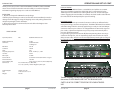
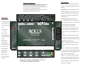
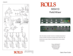
J4
CH 4
J3
CH 3
J2
CH 2
J1
CH 1
2
3
3
3
SW1E
47U
+VB
47U
C404
5
47U R404332 1%
R405332 1% 6
R403
33K
Vph
10
47U
C304
47U
C303
SW1G
3
47U R304332 1%
R305332 1% 2
47U
R402 SW DIP-8
4.99K 1%
C401
C402
7
+VB
R303
33K
Vph
12
47U
C204
47U
C203
47U
XLR F PC C403
R401
4.99K 1%
5
3
47U R204332 1%
R205332 1% 2
R203
33K
+VB
47U
R302 SW DIP-8
4.99K 1%
C301
C302
XLR F PC
R301
4.99K 1%
XLR F PC
3
3
Vph
14
47U
C104
47U
C103
SW1C
5
47U R104332 1%
R105332 1% 6
47U
R202 SW DIP-8
4.99K 1%
C201
C202
XLR F PC
R201
4.99K 1%
1
2
1
2
1
2
1
27
U2A
C305
220PF
C405
220PF
+V
C306
220PF
C406
220PF
U2B
61
87
33K
R406
4560
33K
R306
4560
33K
41
C206
220PF
4560
33K
R106
4560
R206
U1A
C205
220PF
C106
220PF
U1B
P1
C407
.1
SW DIP-8
SW1H
1
2
4
8
7
5
1
2
4
9
8
7
5
1
2
4
11 8
7
5
+VB
P4
P100K
C307
.1
SW DIP-8
SW1F
+VB
P3
P100K
C207
.1
SW DIP-8
SW1D
13
+VB
P2
P100K
C107
.1
SW DIP-8
SW1B
15 8
7
5
+VB
P100K
6
R108
22K
DP3THOR
SW7B
DP3THOR
SW7A
DP3THOR
SW6B
DP3THOR
SW6A
DP3THOR
SW5B
DP3THOR
SW5A
22K
R407
6
22K
R408
3
22K
R307
6
22K
R308
3
22K
R207
6
22K
R208
3
R107
DP3THOR 22K
SW4B
DP3THOR
3
R1
1K
10K
10K
R109
R209
+VB
3
2
100K
27PF
+VB
5
6
1
47U
R309
47K
C2
C409
6
C4
47U
SW3B
LINE IN
J6
DPDT
R16
1K
7
R310
1K
3.5STJK
47K
R15
4556
U3B
4
C3 R4
100K
27PF
+V
1U C408
1U
R3
1K
4556
U3A
R2
C1
4
8
4
4
8
8
OUTPUTS
+
POWER
OFF - ON
3.5mm
LEFT
MIC
LINE
RIGHT
SW4A
Phan Pwr ON=dwn
Low Cut ON=up
5
T2
100
C13
2
1K
1K
R26
R25
3
4
5
3
J7
D10
47U
BA6144
U8
D12
D11 D13
D5
D7
D6 D8
R22
10K
left
D9
2
LEFT OUT
C10
10U
R20
R21
47K
10K
C38
.047
C9
10U
R19
R18
47K
10K
C27
.047
RIGHT OUT
J9
www.rolls.com
3
+20
L C R
USA
+20
BATTERIES
9V x 2
2
3
R8
22K
22K
R9
+VB
3
2
U6B
U6A
SPST
SW2
47U
C7
1
Q2
2N3906
+VB
7
C11
47U
E6
2
3
E31
1
JAPDC
J8
IN 9-15 VDC
Document Number:
FXa MX410.SCH
Date: 21 September 2009
Size:
Murray, Utah
5968 S 350 W
Sheet
84107
Rolls Corporation
WIRE
WIRE
MX410 Sound Man
1
1
1BATT
E1
WIRE
D3
5.1V
D4
5.1V
D2
LDRG
R11
2K
+V
R40
50
47U
HDPHN
J13
HDPHN
3.5STJK
R39
50
Title
WIRE
C12
E2
WIRE
1
AUX OUT/
4556
4556
P100K X2
P5B
4
+VB
5
6
E4
WIRE
BT1
BAT 9V
C6
E5
1
1K UF
WIRE
BT2
BAT 9V
E7
1N4001
D1
P100K X2
P5A
1
+V
Q3 Vph
2N3904
6
3
10K
R13
R24
10K
10K
R23
+V
47U
C5
R12
22K
J5
XLR M PC
OUT
0/-30 LINE OUT
1
3.5STJK
R10
680
3
CLIP
10K
R17
R14 XLR M PC
OUT
P/N 829
T1
BA6144
U7
3
4
5
2 1
680
P/N 829
+V R51
1
2
3
DPDT
1
SW3A
2
5
1
2
4
L C R
AUX
INPUT
+20
4
2
CHANNEL
LEVEL
3
C R
IN
CHANNEL
L
INPUTS
LEVEL
Four Channel
Field Mixer
2
MADE
CHANNEL
+20
MAN
AUX
INPUT
1
MX410
2
1
8
4
C105
220PF
+V
INPUTS
RIGHT
MIC
LINE
L C R
LEFT
Stereo
LEVEL
4
PUSH
PUSH
Phantom
Low Cut
Phantom
Low Cut
Phantom
Low Cut
Phantom
Low Cut
USA
R41
R42
R43
R44
R46
R47
R48
R49
1
SW1A
Vph
1
16
+VB
R102 SW DIP-8
R103
4.99K 1%
33K
C101
C102
www.rolls.com
R45
R50
1
4.7K 1
4.7K 2
4.7K 3
4.7K 4
5
4.7K 6
7
8
9
D14
4.7K 1
4.7K 2
4.7K 3
4.7K 4
5
4.7K 6
7
8
9
1
4
CHANNEL
LEVEL
Stereo
SOUND
CHANNEL
IN
3
Four Channel
Field Mixer
CHANNEL
2
MADE
CHANNEL
1
MAN
ROLLS CORPORATION
SALT LAKE CITY, UTAH
6/11
CHANNEL
SOUND
BATTERIES
9V x 2
R101
4.99K 1%
Rev:
A
1 of 1
SCHEMATIC
MX410
Field Mixer
Phantom
Low Cut
Phantom
Low Cut
Phantom
Low Cut
Phantom
Low Cut
Phan Pwr ON=dwn
Low Cut ON=up
OUTPUTS
3.5mm
right
PWR
HEADPHONE
PUSH
POWER
OFF - ON
+
-
MX410
LEVEL
MX410
ENG MIXER
PUSH
NOTE: THIS MANUAL ASSUMES THE USER HAS A WORKING KNOWLEDGE OF
AUDIO ELECTRONICS, BALANCED AND UNBALANCED CONNECTIONS, AND
PROPER SIGNAL LEVEL SETTINGS. FOR PROPER SETUP AND USE CONTACT
YOUR DEALER.
ROLLS CORPORATION
5968 South 350 West
Salt Lake City, UT 84107
Phone (801) 263-9053
FAX (801) 263-9068
www.rolls.com
Quick Start Guide
OPERATION AND SET UP CONT.
INTRODUCTION
CHANNEL
CHANNEL
CHANNEL
1
2
3
AUX
INPUT
CHANNEL
4
RIGHT
3.5mm
POWER
OFF - ON
+
-
OUTPUTS
MADE
IN
BATTERIES
9V x 2
Phan Pwr ON=dwn
Low Cut ON=up
USA
www.rolls.com
SOUND
LEVEL
Four Channel
Field Mixer
MAN
LEVEL
Stereo
MX410
LEVEL
LEVEL
LEVEL
left
right
L
+20
C R
+20
L C R
+20
L C R
3
2
PWR
L C R
4
Stereo
+20
1
MX410
ENG MIXER
HEADPHONE
MX410
USA
Phan Pwr ON=dwn
Low Cut ON=up
Phantom
Low Cut
Phantom
Low Cut
Phantom
Low Cut
Phantom
Low Cut
OUTPUTS
INPUTS
4
3
2
1
CHANNEL
CHANNEL
CHANNEL
CHANNEL
AUX
INPUT
RIGHT
MIC
LINE
LEFT
3.5mm
POWER
OFF - ON
+
-
PUSH
Power Adapter:
Size:
Weight:
LEFT
MIC
LINE
INPUTS
Phantom
Low Cut
Phantom
Low Cut
Phantom
Low Cut
Phantom
Low Cut
IN
-30 dB
-65 dB maximum
-90 dB typical
+55 db
115 dB
.05%
20 Hz - 20 kHz | +0, -3 dB
100 Hz
-20 dBV
30 mA with no Phantom Power or Signal.
+18 VDC
18 Hrs. (2 mics, phan on, with headphone)
4 ea. Female XLR, 2 ea. Male XLR,
3 ea. 1/8” (3.5mm), 1 Center Negative power jack.
Four Channel
Field Mixer
Output Attenuator:
Self Noise:
Max Gain:
S/N Ratio:
THD:
Frequency Response:
Low Cut:
Max Input:
Current Draw:
Phantom Power:
Typical Battery Life:
Connectors:
600 Ohms XLR balanced
www.rolls.com
Mic:
BATTERIES
9V x 2
Input Impedance:
MADE
SPECIFICATIONS
PHANTOM POWER
The MX410 can provide up to 10 mA of current to each input, sufficient for the
most power-hungry condenser microphones. The MX410 Phantom Power utilizes
a fixed DC voltage which is resistively applied to pin-2 and pin-3 of an XLR input
connector relative to pin-1 (there is no voltage difference between the signal on
pins 2 and 3; a dynamic microphone may or may not operate normally in the
presence of phantom power).
It is generally a good practice to turn off phantom powering when not using a
condenser microphone, as it can capacitively couple noise into the mic inputs
with poor mic cables. Also, be sure to turn off phantom powering when using ribbon microphones since an improperly wired cable can permanently damage the
microphone.
MAN
INSPECTION
1. Unpack and inspect the MX410 box and package.
If obvious physical damage is noticed, contact the carrier immediately to make a
damage claim. We suggest saving the shipping carton and packing materials for
safely transporting the unit in the future.
2. Please visit our web site at www.rolls.com and click on the Register Your
Warranty Here button.
LOW-CUT FILTERS
Each channel of the MX410 features a switchable Low-Cut filter set at 100Hz.
These Low-Cut filters (sometimes called “High Pass”) cut frequencies below
100Hz signal and are effective for reducing wind noise. For several audio applications engaging the Low-Cut filter is beneficial, since little usable audio information exists below 100 Hz. Especially for speech recording.
SOUND
Thank your for your purchase of the Rolls MX410 Field Mixer; Professional ENG
mixer. Please read and review this manual carefully as it contains important
information regarding the proper use and care of the MX410.
PUSH
PUSH
PUSH
12VDC / 200 mA
9” W x 6.75” D x 1.5” H
2.45 lbs
Trouble shooting: The MX410 is designed to be an easy to use full function mixer. PLEASE MAKE SURE THAT THE REAR MIC/LINE
SWITCH IS IN THE CORRECT POSITION FOR YOUR INTENDED
USE.
page 1
www.rolls.com
www.rolls.com
page 6
FEATURES
OPERATION AND SET UP
POWERING
We recommend using 9V alkaline type batteries, however Lithium or NiMH batteries work as well.
For AC power, Rolls provides the model # PS27 12 VDC supply to power the
MX410.
INPUT CHANNELS
The inputs to the MX410 consist of four, microphone preamplifiers. Each channel
has sufficient gain to accommodate nearly all microphone types.
The MX410 input channels can be used with balanced or unbalanced connections. When unbalancing - ground pin-3 to pin-1.
The AUX INPUT jack is provided for recording stereo sources such as CD players, MP3 and DVD players, etc.
OUTPUTS
The MX410 is designed with two individual balanced male XLR output jacks.
Each output is isolated providing excellent signal connectivity and noise performance.
These outputs are generally connected to a recording device or other input looking for a line-level signal. In the event you need to connect the MX410 output to
a mixer’s Microphone Input, set the Output Level select switch to MIC level. This
way the MX410 output is attenuated down, and will be more compatible with an
input looking for a microphone level signal.
INDIVIDUAL CHANNEL LEVEL CONTROLS
The Level is the primary channel volume control. Level can be set to a nominal
level (around 12 O’clock) providing the maximum amount of variance and headroom.
L C R SWITCHES (Left - Center - Right)
The Stereo orientation switches routes an input channels signal between the
Left, Right and both outputs.
- Four balanced XLR Inputs
- Two transformer-balanced XLR Outputs
- Switchable Output Level ( Line level, or Mic level)
- 1/8” TRS Stereo Auxiliary Input
- Switchable Phantom Power for each input
- Switchable 100 Hz Low Cut filters for each input
- Dual 9V easy access Battery compartment
- Level controls for each channel
- 1/8” (3.5mm) Headphone/Earphone Output with Level control
- 18 hour battery life (with 2 condenser mics using phantom power and head
phones attached, constant use).
- Rolls PS27 external power supply included
QUICK START GUIDE
For those familiar with ENG or field mixers, this guide highlights basic functionality to
begin operating your MX410.
POWERING
To power the MX410 and get it ready for operation:
1. Insert - 2, 9-Volt, alkaline batteries into the battery compartments. Insert with the correct
polarity.
Or, connect external DC power (the Rolls PS27) 12 VDC to the MX410 DC Input connector.
2. Press in the POWER button.
INPUT CHANNEL SETUP
To set up a gain level for an input channel:
1. Connect a signal source (microphone) to a channel input connector.
2. If you’re using a condenser microphone, activate the Phantom Power by depressing the
phan switch.
3. Set the LEVEL Control at the 12 O’clock position (again - just a starting point).
4. Set the channel L C R switch for the desired signal position in the stereo field.
5. Engage the side panel “low cut” switch if needed. To reduce unwanted wind noise.
6. Verify there is signal present on the output meter(s).
OUTPUT CONNECTION
To connect to the MX410 main Outputs:
1. Connect an XLR cable to the LEFT and RIGHT Outputs of the MX410.
2. Set the output level switch to either LINE (switch in), or MIC (switch out).
3. Verify that the next device in the signal chain is receiving signal from the MX410.
HEADPHONE MONITORING
METERING
The MX410 features two calibrated, LED meters. Meter ballistics correspond
closely to how the human ear perceives loudness and provides a good visual
indication of how loud a signal will be.
page 5
www.rolls.com
1. Connect stereo headphones to the HEADPHONE output on the front panel. NOTE:
THESE MUST BE STEREO HEADPHONES OR EARPHONES - USING MONO PHONES
WILL DAMAGE THE MX410.
2. Set the PHONES level to 0.
3. Verify signal in the phones by slowly bringing up the PHONES level control.
4. Set the PHONES level control to a comfortable level.
www.rolls.com
page 2
REAR PANEL/TOP
REAR PANEL CONNECTIONS
Connect your microphones to the MX410 using balanced
XLR cables. Connect the MX410 Outputs to the next
device in your signal chain (usually a recording device of
some kind), also via balanced XLR cables.
For monitoring external signal sources, connect a stereo
(Tip-Ring-Sleeve) plug to the Aux Input.
12VDC / 100 mA: Power input connector.
Connects to the optional Rolls PS27 Power
Adapter.
POWER: Button - turns the MX410 on and
off. This switch has been designed to not
switch accidently. It is small and recessed
by design, so it will not turn off until you
intend to do so.
FRONT PANEL
PUSH
PUSH
PUSH
CHANNEL
CHANNEL
CHANNEL
CHANNEL
1
2
3
4
of signal from the
3.5mm
POWER
OFF - ON
is configured ”hot”, pin 3 is neutral, and pin
+
-
OUTPUTS
1 is connected to chassis ground.
Phantom
Low Cut
Phantom
Low Cut
Phantom
Low Cut
Phantom
Low Cut
OUTPUT LEVEL (MIC / LINE): When
Phan Pwr ON=dwn
Low Cut ON=up
4: Adjusts the
MADE IN USA
relative Right/Left
www.rolls.com
BATTERIES
9V x 2
1, 2, 3, and
signal level to the
outputs.
HEADPHONE
pressed in, outputs are at MIC level when
out the outputs are at LINE level. A 1/8”
3.5mm T R S jack is also provided for the
output.
AUX INPUT: 1/8” Tip-Ring-Sleeve jack for
connection to an auxiliary line-level stereo
signal such as the output of another mixer,
Four Channel Stereo
Field Mixer
SOUND MAN
BATTERY
L C R SWITCH
INPUTS
LEFT
MIC
LINE
LIFT TO WITHDRAW
Input.
RIGHT
BATTERY
corresponding Mic
jacks containing the main mix signal. Pin 2
AUX
INPUT
LIFT TO WITHDRAW
4: Adjust the level
LEFT/RIGHT OUTPUT: Balanced XLR
PUSH
LEVEL 1, 2, 3, and
MX410
AM/FM tuner, CD player, etc.
LEVEL: Adjusts
INPUTS 1 - 4: Balanced XLR jacks for con-
the level of signal
nection to dynamic or condenser micro-
from the Head-
phones.
phone Output.
PHAN 1 - 4: When the switch is DOWN for
HEADPHONE
the corresponding channel Phantom Power
LEVEL
LEVEL
LEVEL
LEVEL
LEVEL
Ring-Sleeve 1/8”
right
+20
1
L
+20
C R
2
+20
L C R
3
+20
L C R
4
L C R
PWR
HEADPHONE
(3.5 mm) Tip-RingSleeve jack.
is applied to the corresponding Input. See
left
OUTPUT: Tip-
IMPORTANT NOTICE: DO NOT PLUG MONO (TipSleeve) PLUGS INTO HEADPHONE JACK. DOING SO WILL DAMAGE THE MX410.
top screening for explanation.
MX410
ENG MIXER
LOW CUT 1 - 4: When the switch is UP for
the corresponding channel it reduces the
low frequency (100Hz and below) of the
corresponding Input signal. To decrease
wind noise or popping.