1
Information
When you need repair service, call your nearest Roland Service Center or authorized Roland distributor in your country as
shown below.
AFRICA
EGYPT
Al Fanny Trading Office
9, EBN Hagar A1 Askalany Street,
ARD E1 Golf, Heliopolis,
Cairo 11341, EGYPT
TEL: 20-2-417-1828
REUNION
Maison FO - YAM Marcel
25 Rue Jules Hermann,
Chaudron - BP79 97 491
Ste Clotilde Cedex,
REUNION ISLAND
TEL: (0262) 218-429
SINGAPORE
Swee Lee Company
150 Sims Drive,
SINGAPORE 387381
TEL: 846-3676
CRISTOFORI MUSIC PTE
LTD
Blk 3014, Bedok Industrial Park E,
#02-2148, SINGAPORE 489980
TEL: 243 9555
TAIWAN
PANAMA
ITALY
ISRAEL
SUPRO MUNDIAL, S.A.
Roland Italy S. p. A.
Boulevard Andrews, Albrook,
Panama City, REP. DE PANAMA
TEL: 315-0101
Viale delle Industrie 8,
20020 Arese, Milano, ITALY
TEL: (02) 937-78300
Halilit P. Greenspoon &
Sons Ltd.
PARAGUAY
NORWAY
Distribuidora De
Instrumentos Musicales
J.E. Olear y ESQ. Manduvira
Asuncion PARAGUAY
TEL: (021) 492-124
245 Prince Mohammad St.,
Amman 1118, JORDAN
TEL: (06) 464-1200
Easa Husain Al-Yousifi
POLAND
Portinari 199 (ESQ. HALS),
San Borja, Lima 41,
REP. OF PERU
TEL: (01) 4758226
P. P. H. Brzostowicz
SOUTH AFRICA
Room 5, 9fl. No. 112 Chung Shan
N.Road Sec.2, Taipei, TAIWAN,
R.O.C.
TEL: (02) 2561 3339
VIDEO Broadcast S.A.
UL. Gibraltarska 4.
PL-03664 Warszawa POLAND
TEL: (022) 679 44 19
That Other Music Shop
(PTY) Ltd.
THAILAND
URUGUAY
PORTUGAL
Paul Bothner (PTY) Ltd.
17 Werdmuller Centre,
Main Road, Claremont 7708
SOUTH AFRICA
P.O.BOX 23032, Claremont 7735,
SOUTH AFRICA
TEL: (021) 674 4030
ASIA
CHINA
Beijing Xinghai Musical
Instruments Co., Ltd.
6 Huangmuchang Chao Yang
District, Beijing, CHINA
TEL: (010) 6774 7491
Shanghai Xingtong Acoustics
Equipment CO.,Ltd.
5F. No.1500 Pingliang Road
New East Club Plaza, Shanghai,
CHINA
TEL: (021) 5580-0800
HONG KONG
Tom Lee Music Co., Ltd.
Service Division
22-32 Pun Shan Street, Tsuen
Wan, New Territories,
HONG KONG
TEL: 2415 0911
INDIA
Rivera Digitec (India) Pvt. Ltd.
409, Nirman Kendra Mahalaxmi
Flats Compound Off. Dr. Edwin
Moses Road, Mumbai-400011,
INDIA
TEL: (022) 498 3079
INDONESIA
VIETNAM
ROMANIA
Av. Francisco de Miranda,
Centro Parque de Cristal, Nivel
C2 Local 20 Caracas
VENEZUELA
TEL: (212) 285-8586
Piata Libertatii 1,
RO-4200 Gheorghehi
TEL: (095) 169-5043
AUSTRIA
Roland Corporation
Australia Pty., Ltd.
38 Campbell Avenue
Dee Why West. NSW 2099
AUSTRALIA
TEL: (02) 9982 8266
NEW ZEALAND
Roland Corporation Ltd.
32 Shaddock Street, Mount Eden,
Auckland, NEW ZEALAND
TEL: (09) 3098 715
CENTRAL/LATIN
AMERICA
ARGENTINA
Instrumentos Musicales S.A.
Av.Santa Fe 2055
(1123) Buenos Aires
ARGENTINA
TEL: (011) 4508-2700
BRAZIL
Roland Brasil Ltda
Rua San Jose, 780 Sala B
Parque Industrial San Jose
Cotia - Sao Paulo - SP, BRAZIL
TEL: (011) 4615 5666
COSTA RICA
J1. Cideng Timur No. 15J-150
Jakarta Pusat
INDONESIA
TEL: (021) 6324170
JUAN Bansbach
Instrumentos Musicales
Ave.1. Calle 11, Apartado 10237,
San Jose, COSTA RICA
TEL: 258-0211
Cosmos Corporation
CHILE
1461-9, Seocho-Dong,
Seocho Ku, Seoul, KOREA
TEL: (02) 3486-8855
Comercial Fancy S.A.
MALAYSIA
BENTLEY MUSIC SDN BHD
140 & 142, Jalan Bukit Bintang
55100 Kuala Lumpur, MALAYSIA
TEL: (03) 2144-3333
PHILIPPINES
G.A. Yupangco & Co. Inc.
339 Gil J. Puyat Avenue
Makati, Metro Manila 1200,
PHILIPPINES
TEL: (02) 899 9801
Rut.: 96.919.420-1
Nataniel Cox #739, 4th Floor
Santiago - Centro, CHILE
TEL: (02) 688-9540
EL SALVADOR
OMNI MUSIC
75 Avenida Norte y Final
Alameda Juan Pablo ,
Edificio No.4010 San Salvador,
EL SALVADOR
TEL: 262-0788
MEXICO
Casa Veerkamp, s.a. de c.v.
Av. Toluca No. 323, Col. Olivar
de los Padres 01780 Mexico D.F.
MEXICO
TEL: 668-0480
Roland Austria GES.M.B.H.
Siemensstrasse 4, P.O. Box 74,
A-6063 RUM, AUSTRIA
TEL: (0512) 26 44 260
BELGIUM/HOLLAND/
LUXEMBOURG
Roland Benelux N. V.
Houtstraat 3, B-2260, Oevel
(Westerlo) BELGIUM
TEL: (014) 575811
DENMARK
Roland Scandinavia A/S
Nordhavnsvej 7, Postbox 880,
DK-2100 Copenhagen
DENMARK
TEL: (039)16 6200
FRANCE
Roland France SA
4, Rue Paul Henri SPAAK,
Parc de l'Esplanade, F 77 462 St.
Thibault, Lagny Cedex FRANCE
TEL: 01 600 73 500
FINLAND
Roland Scandinavia As,
Filial Finland
Lauttasaarentie 54 B
Fin-00201 Helsinki, FINLAND
TEL: (9) 682 4020
GERMANY
Roland Elektronische
Musikinstrumente HmbH.
FBS LINES
Warehouse Area ‘DEPO’ Pf.83
H-2046 Torokbalint, HUNGARY
TEL: (23) 511011
IRELAND
Roland Ireland
Audio House, Belmont Court,
Donnybrook, Dublin 4.
Republic of IRELAND
TEL: (01) 2603501
Corniche Road, Aldossary Bldg.,
1st Floor, Alkhobar,
SAUDI ARABIA
SPAIN
P.O.Box 2154, Alkhobar 31952
SAUDI ARABIA
TEL: (03) 898 2081
Roland Electronics
de España, S. A.
Calle Bolivia 239, 08020
Barcelona, SPAIN
TEL: (93) 308 1000
SYRIA
Technical Light & Sound
Center
SWEDEN
Bldg. No. 47,
Khaled Ebn Al Walid St.
Damascus, SYRIA
TEL: (011) 221-1230
Roland Scandinavia A/S
SWEDISH SALES OFFICE
Danvik Center 28, 2 tr.
S-131 30 Nacka SWEDEN
TEL: (08) 702 0020
TURKEY
Barkat muzik aletleri ithalat
ve ihracat Ltd Sti
SWITZERLAND
Roland (Switzerland) AG
Musitronic AG
Gerberstrasse 5, Postfach,
CH-4410 Liestal, SWITZERLAND
TEL: (061) 927-8383
UKRAINE
Mira Str. 19/108
P.O. Box 180
295400 Munkachevo, UKRAINE
TEL: (03131) 414-40
UNITED KINGDOM
Roland (U.K.) Ltd.
Atlantic Close, Swansea
Enterprise Park, SWANSEA
SA7 9FJ,
UNITED KINGDOM
TEL: (01792) 700139
U.A.E.
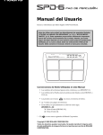
Thank you, and congratulations on your choice of the SPD-20
Total Percussion Pad. The SPD-20 is an electronic percussion unit
that has eight pads, trigger interfaces, a high-quality digital sound
generator, and on-board digital effects.
Since the SPD-20 includes a sound generator and effects in one
lightweight, compact package, you can use it anywhere, anytime.
A wide variety of options (pads, pedals, drum stand, etc.) are
available, allowing you to easily create a custom drum kit. By
adding sequencers or samplers, you can take advantage of the
possibilities of MIDI percussion.
The SPD-20 provides the flexibility and expandability that will be
appreciated by every percussionist, from beginner to professional.
About the Symbols in This Manual
Words or symbols enclosed in [square brackets] indicate panel
buttons or controls.
For example, [LAYER] signifies the Layer button.
Zabeel Road, Al Sherooq Bldg.,
No. 14, Grand Floor, Dubai, U.A.E.
TEL: (04) 3360715
Items marked by
NORTH AMERICA
Items headed by NOTE explain important points concerning the
operation of your SPD-20.
Roland Canada Music Ltd.
(Head Office)
5480 Parkwood Way Richmond
B. C., V6V 2M4 CANADA
TEL: (0604) 270 6626
MEMO
are supplementary explanations.
Items preceded by
give you useful tips and information
regarding the use of the SPD-20.
Roland Canada Music Ltd.
(Toronto Office)
Unit 2, 109 Woodbine Downs
Blvd, Etobicoke, ON
M9W 6Y1 CANADA
TEL: (0416) 213 9707
No.16, Bab Al Bahrain Avenue,
P.O.Box 247, Manama 304,
State of BAHRAIN
TEL: 211 005
U. S. A.
Roland Corporation U.S.
CYPRUS
Radex Sound Equipment Ltd.
5100 S. Eastern Avenue
Los Angeles, CA 90040-2938,
U. S. A.
TEL: (323) 890 3700
IRAN
MOCO, INC.
No.41 Nike St., Dr.Shariyati Ave.,
Roberoye Cerahe Mirdamad
Tehran, IRAN
TEL: (021) 285-4169
OWNER’S MANUAL
CANADA
Moon Stores
17, Diagorou Street, Nicosia,
CYPRUS
TEL: (02) 66-9426
Siraselviler Caddesi Siraselviler
Pasaji No:74/20
Taksim - Istanbul, TURKEY
TEL: (0212) 2499324
Zak Electronics & Musical
Instruments Co. L.L.C.
TIC-TAC
GREECE
Intermusica Ltd.
aDawliah Universal
Electronics APL
3-Bogatyrskaya Str. 1.k.l
107 564 Moscow, RUSSIA
TEL: (095) 169 5043
BAHRAIN
HUNGARY
SAUDI ARABIA
MuTek
MIDDLE EAST
155, New National Road
Patras 26442, GREECE
TEL: (061) 43-5400
P.O. Box 62,
Doha, QATAR
TEL: 4423-554
RUSSIA
Oststrasse 96, 22844 Norderstedt,
GERMANY
TEL: (040) 52 60090
STOLLAS S.A.
Music Sound Light
Gerge Zeidan St., Chahine Bldg.,
Achrafieh, P.O.Box: 16-5857
Beirut, LEBANON
TEL: (01) 20-1441
Al Emadi Co. (Badie Studio
& Stores)
Musicland Digital C.A.
AUSTRALIA
A. Chahine & Fils
QATAR
VENEZUELA
EUROPE
LEBANON
Cais Das Pedras, 8/9-1 Dto
4050-465 PORTO
PORTUGAL
TEL: (022) 608 00 60
138 Tran Quang Khai St.,
District 1
Ho Chi Minh City
VIETNAM
TEL: (08) 844-4068
AUSTRALIA/
NEW ZEALAND
Abdullah Salem Street,
Safat, KUWAIT
TEL: 243-6399
Tecnologias Musica e Audio,
Roland Portugal, S.A.
Saigon Music
PT Citra IntiRama
KOREA
Francisco Acuna de Figueroa 1771
C.P.: 11.800
Montevideo, URUGUAY
TEL: (02) 924-2335
KUWAIT
OWNER’S MANUAL
P.O.Box 32918, Braamfontein 2017
Johannesbourg, SOUTH AFRICA
TEL: (011) 403 4105
330 Verng NakornKasem, Soi 2,
Bangkok 10100, THAILAND
TEL: (02) 2248821
Todo Musica S.A.
AMMAN Trading Agency
Lilleakerveien 2 Postboks 95
Lilleaker N-0216 Oslo
NORWAY
TEL: 273 0074
PERU
Theera Music Co. , Ltd.
JORDAN
Roland Scandinavia Avd.
Kontor Norge
ROLAND TAIWAN
ENTERPRISE CO., LTD.
11 Melle St., Braamfontein,
Johannesbourg, SOUTH AFRICA
8 Retzif Ha'aliya Hashnya St.
Tel-Aviv-Yafo ISRAEL
TEL: (03) 6823666
As of January 1, 2002 (Roland)
Before using this unit, carefully read the sections entitled: “USING THE UNIT SAFELY” and “IMPORTANT
NOTES” (Owner’s manual p. 2; p. 6). These sections provide important information concerning the proper operation of
the unit. Additionally, in order to feel assured that you have
gained a good grasp of every feature provided by your new
unit, Owner‘s manual should be read in its entirety. The manual should be saved and kept on hand as a convenient reference.
Copyright 1998
ROLAND CORPORATION
All rights reserved. No part of this publication may be reproduced in any
form without the written permission of ROLAND CORPORATION.
01453923
'02-2-AE2-61N
For the U.K.
IMPORTANT: THE WIRES IN THIS MAINS LEAD ARE COLOURED IN ACCORDANCE WITH THE FOLLOWING CODE.
BLUE:
NEUTRAL
BROWN: LIVE
Used for instructions intended to alert
the user to the risk of death or severe
injury should the unit be used
improperly.
Used for instructions intended to alert
the user to the risk of injury or material
damage should the unit be used
improperly.
* Material damage refers
other adverse effects
respect to the home
furnishings, as well
animals or pets.
to damage or
caused with
and all its
to domestic
The
symbol alerts the user to important instructions
or warnings.The specific meaning of the symbol is
determined by the design contained within the
triangle. In the case of the symbol at left, it is used for
general cautions, warnings, or alerts to danger.
The
symbol alerts the user to items that must never
be carried out (are forbidden). The specific thing that
must not be done is indicated by the design contained
within the circle. In the case of the symbol at left, it
means that the unit must never be disassembled.
The ● symbol alerts the user to things that must be
carried out. The specific thing that must be done is
indicated by the design contained within the circle. In
the case of the symbol at left, it means that the powercord plug must be unplugged from the outlet.
As the colours of the wires in the mains lead of this apparatus may not correspond with the coloured markings identifying
the terminals in your plug, proceed as follows:
The wire which is coloured BLUE must be connected to the terminal which is marked with the letter N or coloured BLACK.
The wire which is coloured BROWN must be connected to the terminal which is marked with the letter L or coloured RED.
Under no circumstances must either of the above wires be connected to the earth terminal of a three pin plug.
For EU Countries
CAUTION
Danger of explosion if battery is
incorrectly replaced.
Replace only with the same or
equivalent type recommended by the
manufacturer.
Discard used batteries according to the
manufacturer’s instructions.
Apparatus containing
Lithium batteries
ADVARSEL!
VARNING
Lithiumbatteri - Eksplosionsfare ved
fejlagtig håndtering.
Udskiftning må kun ske med batteri af
samme fabrikat og type.
Levér det brugte batteri tilbage til
leverandøren.
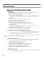
• Before using this unit, make sure to read the
instructions below, and the Owner's Manual.
.........................................................................................................
• Do not open (or modify in any way) the unit or its
AC adaptor.
.........................................................................................................
• Do not attempt to repair the unit, or replace parts
within it (except when this manual provides specific instructions directing you to do so). Refer all
servicing to your retailer, the nearest Roland
Service Center, or an authorized Roland distributor, as listed on the "Information" page.
.........................................................................................................
• Never use or store the unit in places that are:
• Subject to temperature extremes (e.g., direct
sunlight in an enclosed vehicle, near a heating
duct, on top of heat-generating equipment); or
are
• Damp (e.g., baths, washrooms, on wet floors);
or are
• Humid; or are
• Dusty; or are
• Subject to high levels of vibration.
.........................................................................................................
• When using the unit with a rack or stand recommended by Roland, the rack or stand must be carefully placed so it is level and sure to remain stable.
If not using a rack or stand, you still need to make
sure that any location you choose for placing the
unit provides a level surface that will properly
support the unit, and keep it from wobbling.
.........................................................................................................
• Be sure to use only the AC adaptor supplied with
the unit. Also, make sure the line voltage at the
installation matches the input voltage specified on
the AC adaptor's body. Other AC adaptors may
use a different polarity, or be designed for a different voltage, so their use could result in damage,
malfunction, or electric shock.
.........................................................................................................
• Avoid damaging the power cord. Do not bend it
excessively, step on it, place heavy objects on it,
etc. A damaged cord can easily become a shock or
fire hazard. Never use a power cord after it has
been damaged.
.........................................................................................................
• This unit, either alone or in combination with an
amplifier and headphones or speakers, may be
capable of producing sound levels that could cause
permanent hearing loss. Do not operate for a long
period of time at a high volume level, or at a level
that is uncomfortable. If you experience any hearing loss or ringing in the ears, you should immediately stop using the unit, and consult an audiologist.
.........................................................................................................
• Do not allow any objects (e.g., flammable material,
coins, pins); or liquids of any kind (water, soft
drinks, etc.) to penetrate the unit.
Explosionsfara vid felaktigt batteribyte.
Använd samma batterityp eller en
ekvivalent typ som rekommenderas av
apparattillverkaren.
Kassera använt batteri enligt
fabrikantens instruktion.
ADVARSEL
VAROITUS
Eksplosjonsfare ved feilaktig skifte av
batteri.
Benytt samme batteritype eller en
tilsvarende type anbefalt av
apparatfabrikanten.
Brukte batterier kasseres i henhold til
fabrikantens instruks joner.
Paristo voi räjähtää, jos se on
virheellisesti asennettu.
Vaihda paristo ainoastaan
laitevalmistajan suosittelemaan
tyyppiin. Hävitä käytetty paristo
valmistajan ohjeiden mukaisesti.
For EU Countries
This product complies with the requirements of European Directive 89/336/EEC.
For the USA
FEDERAL COMMUNICATIONS COMMISSION
RADIO FREQUENCY INTERFERENCE STATEMENT
This equipment has been tested and found to comply with the limits for a Class B digital device, pursuant to Part 15 of the
FCC Rules. These limits are designed to provide reasonable protection against harmful interference in a residential
installation. This equipment generates, uses, and can radiate radio frequency energy and, if not installed and used in
accordance with the instructions, may cause harmful interference to radio communications. However, there is no guarantee
that interference will not occur in a particular installation. If this equipment does cause harmful interference to radio or
television reception, which can be determined by turning the equipment off and on, the user is encouraged to try to correct the
interference by one or more of the following measures:
– Reorient or relocate the receiving antenna.
– Increase the separation between the equipment and receiver.
– Connect the equipment into an outlet on a circuit different from that to which the receiver is connected.
– Consult the dealer or an experienced radio/TV technician for help.
Unauthorized changes or modification to this system can void the users authority to operate this equipment.
This equipment requires shielded interface cables in order to meet FCC class B Limit.
For Canada
.........................................................................................................
NOTICE
This Class B digital apparatus meets all requirements of the Canadian Interference-Causing Equipment Regulations.
AVIS
Cet appareil numérique de la classe B respecte toutes les exigences du Règlement sur le matériel brouilleur du Canada.
2
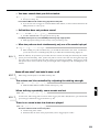
• Immediately turn the power off, remove the AC
adaptor from the outlet, and request servicing by
your retailer, the nearest Roland Service Center, or
an authorized Roland distributor, as listed on the
"Information" page when:
• The AC adaptor or the power-supply cord has
been damaged; or
• Objects have fallen into, or liquid has been
spilled onto the unit; or
• The unit has been exposed to rain (or otherwise
has become wet); or
• The unit does not appear to operate normally
or exhibits a marked change in performance.
• The unit and the AC adaptor should be located so
their location or position does not interfere with
their proper ventilation.
.........................................................................................................
• Always grasp only the plug or the body of the AC
adaptor when plugging into, or unplugging from,
an outlet or this unit.
.........................................................................................................
• Whenever the unit is to remain unused for an
extended period of time, disconnect the AC adaptor.
1
.........................................................................................................
.........................................................................................................
• In households with small children, an adult should
provide supervision until the child is capable of
following all the rules essential for the safe operation of the unit.
• Try to prevent cords and cables from becoming
entangled. Also, all cords and cables should be
placed so they are out of the reach of children.
.........................................................................................................
.........................................................................................................
• Protect the unit from strong impact.
(Do not drop it!)
• Never climb on top of, nor place heavy objects on
the unit.
.........................................................................................................
.........................................................................................................
• Do not force the unit's power-supply cord to share
an outlet with an unreasonable number of other
devices. Be especially careful when using extension cords—the total power used by all devices
you have connected to the extension cord's outlet
must never exceed the power rating
(watts/amperes) for the extension cord. Excessive
loads can cause the insulation on the cord to heat
up and eventually melt through.
• Never handle the AC adaptor body, or its plugs,
with wet hands when plugging into, or unplugging from, an outlet or this unit.
.........................................................................................................
• Before using the unit in a foreign country, consult
with your retailer, the nearest Roland Service
Center, or an authorized Roland distributor, as listed on the "Information" page.
.........................................................................................................
2
3
.........................................................................................................
• Before moving the unit, disconnect the AC adaptor
and all cords coming from external devices.
4
.........................................................................................................
• Before cleaning the unit, turn off the power and
unplug the AC adaptor from the outlet (p. 12).
.........................................................................................................
• Whenever you suspect the possibility of lightning
in your area, disconnect the AC adaptor from the
outlet.
.........................................................................................................
3
5
Table of Contents
USING THE UNIT SAFELY.............................................2
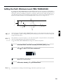
Adjusting the Pad Sensitivity (TRIG SENS) ................30
How to Use This Manual..................................................5
Setting the Pad’s Minimum Level
(TRIG THRESHOLD)......................................................31
Important Notes ................................................................6
Main Features of the SPD-20............................................7
Panel Descriptions.............................................................8
Attaching the SPD-20 to a Drum Stand........................10
Using the Slit Tape (Included).......................................10
How to Restore the Factory Settings
(System Initialize)........................................................11
Copying a Patch (COPY) ................................................32
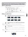
Setting Up Your Own Patch Sequences
(Patch Chain)................................................................33
What is a Patch Chain?........................................................33
Setting up a Patch Chain.....................................................33
Using a Patch Chain to Select Patches ..............................34
Erasing a Patch Chain .........................................................34
CHAPTER 1 Quick Start
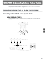
CHAPTER 3 Connecting External Pads or Pedals
Connection to Audio Equipment ..................................12
Connecting External Pads or Hi-Hat Control Pedal ..35
Playing the Pads ..............................................................12
Connecting External Pads or the Special Pedal...............35
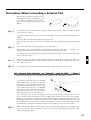
Precautions When Connecting a External Pad................37
Precautions When Connecting
the PD-100 or PD-120......................................................38
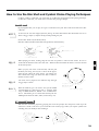
How to Use the Rim Shot and Cymbal Choke
Playing Techniques .........................................................39
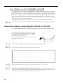
Precautions When Connecting
a Hi-Hat Control Pedal...................................................40
Using a Footswitch as a Hold Pedal..................................41
Turning the Power On ........................................................12
Turning the Power Off ........................................................13
Adjusting the Volume .........................................................13
Selecting a Patch ..............................................................14
What is a Patch? ...................................................................14
Using a Footswitch to Select Patches ................................15
Comparing Layered Sounds ..........................................15
What is a Pad Bank? ............................................................16
What is the Layer Function?...............................................17
CHAPTER 2 Using the SPD-20 by Itself
About the SPD-20’s Internal Setup and Parameter
Settings (Edit)...............................................................18
What Kind of Instrument is the SPD-20? .........................18
Internal Organization ..........................................................18
Play Mode and Edit Mode..................................................19
How to Edit...........................................................................20
Selecting and Adjusting Sounds
(Sound Parameters).....................................................22
Selecting a Sound (INST) ....................................................22
Adjusting the Volume (LEVEL).........................................23
Adjusting the Pitch (PITCH) ..............................................23
Adjusting the Decay (DECAY) ..........................................23
Adjusting the Stereo Position (PAN) ................................23
Adjusting the Dynamic Volume Response (CURVE).....24
Adjusting the Effects Depth (FX SEND)...........................25
How to Edit Sound Parameters .........................................26
Adding Reverberation and Other Effects to the Sound
(Effect Parameters) ......................................................28
Select an Effect (FX TYPE) ..................................................28
Setting Effect Duration and Rate (FX TIME) ...................28
Adjust the Effect Depth for the Entire Patch
(FX LEVEL).......................................................................28
How to Edit Effect Parameters...........................................29
4
Settings for External Pads or Kick Trigger Units........42
Setting External Pad Tone and MIDI Parameters ...........42
How to Edit the Trigger Parameters .................................42
Setting Parameters for Reliable Performance using
Acoustic Drum Triggers and Other Manufacturers’
Pads (Advanced Trigger Parameters)...........................48
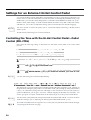
Settings for an External Hi-Hat Control Pedal............54
Controlling the Tone with the Hi-Hat
Control Pedal—Pedal Control (PDL CTRL)................54
Adjusting the Volume of the Pedal Hi-Hat Sound
(PDL LEVEL)....................................................................55
Using the Hi-Hat Control Pedal’s Action to Set
Controller Numbers for Sending and Receiving
MIDI Data (PDL CC#).....................................................56
CHAPTER 4 Connecting MIDI Devices
MIDI Connections ...........................................................57
About MIDI ......................................................................57
How MIDI Data is Sent and Received ..............................57
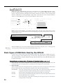
Main Types of MIDI Data Used by the SPD-20...............58
MIDI Parameter Settings ................................................61
How the MIDI Parameters Work ......................................61
Setting MIDI Parameters ....................................................66
Priority Ranking of Note Number Expression ................67
Using the SPD-20 as a MIDI Sound Module ...............67
Setting the Receive Channel (Basic Channel) ..................67
Settings for Each Pad...........................................................68
Using External MIDI Devices to Play the Internal
Sound Generator..............................................................69
Expanding Patches to Allow Reception of Many
Note Numbers (Patch Expand) .....................................69
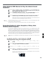
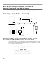
How to Use a Sequencer or a Computer to
Record/Play back Your Performance ......................72
Connecting a Computer (or a Sequencer) ........................72
Breaking/Cutting the Connection Between the Sound
Generator and the Pad Controller (Local Control).....72
How to Set Up the SPD-20 for Sequencing ......................74
Storing the SPD-20’s Data in External Devices
(Bulk Dump) ....................................................................75
How to Transmit (Bulk Dump)..........................................75
How to Receive (Bulk Load) ..............................................76
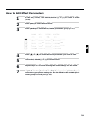
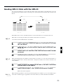
Reading SPD-11 Data with the SPD-20.............................77
What is Device ID ................................................................78
How to Use This Manual
This manual provides a step-by-step introduction to the many
functions of the SPD-20. If this is your first time using electronic drums, or a MIDI device, please read the manual from
beginning to end. If you are already familiar with electronic
percussion and sequencers, you may not need to read the
entire manual. Glance briefly over Chapters 1 & 2, then refer
to other sections as necessary, while you experiment with the
SPD-20. You will soon learn how the unit works. If you don’t
understand the meaning of a term or how a function works,
use the index to find the appropriate explanation.
CHAPTER 1 Quick Start
Read this chapter first to learn how to play using the SPD-20.
It guides you quickly through the basics, up to the point
where you can produce sound. All the fundamental operating procedures are also introduced.
1
CHAPTER 2 Using the SPD-20 by Itself
CHAPTER 5 Supplementary Materials
Troubleshooting...............................................................82
Read this chapter if you wish to use the SPD-20 as a standalone unit. Here you will find a variety of information, such
as how the unit is organized internally, as well as how to
modify the sounds.
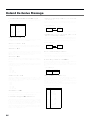
Error Messages.................................................................87
CHAPTER 3 Connecting External Pads or Pedals
Taking Advantage of the On-board Effects.................79
Instrument List.................................................................88
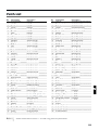
Patch List ..........................................................................93
Read this chapter when you wish to connect external pads or
hi-hat control pedal to the SPD-20.
2
3
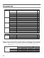
Parameter List ..................................................................94
Trigger Type Internal Parameters
(Advanced Trigger Parameters) ........................................94
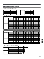
Blank Parameter Chart ...................................................95
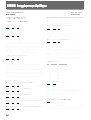
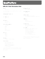
Roland Exclusive Message .............................................96
MIDI Implementation.....................................................98
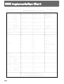
MIDI Implementation Chart........................................102
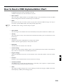
How to Read a MIDI Implementation Chart ............103
Specifications..................................................................104
Index................................................................................105
How-To Index ................................................................106
CHAPTER 4 Connecting MIDI Devices
Read this chapter when you wish to use the SPD-20 to play
an external sound module, to have sequencer performance
data played through the SPD-20, or to save data from the
SPD-20 to a sequencer.
4
CHAPTER 5 Supplementary Materials
Supplementary sections provided with this manual include
“Troubleshooting,” a “Instrument List,” and the “MIDI
Implementation” chart. Read this when, for example, you
need a solution to some difficulty in operating the unit, or
when you just want to know about MIDI in greater detail.
You can find both a subject-specific index and general index
at the end of this manual.
If you will be using the SPD-20 by itself, there is no
MEMO need for you to read Chapters 3 and 4, or the MIDI
Implementation section in Chapter 5 (p. 98–101).
NOTE
The explanations in this manual include illustrations that depict what should typically be
shown by the display. Note, however, that your
unit may incorporate a newer, enhanced version
of the system (e.g., includes newer sounds), so
what you actually see in the display may not
always match what appears in the manual.
5
5
Important Notes
In addition to the items listed under “USING THE UNIT SAFELY” on page 2, please read and observe the following:
Power Supply
Memory Backup
• Do not use this unit on the same power circuit with any
device that will generate line noise (such as an electric
motor or variable lighting system).
• This unit contains a battery which powers the unit’s
memory circuits while the main power is off. When this
battery becomes weak, the message shown below will
appear in the display. Once you see this message, have
the battery replaced with a fresh one as soon as possible
to avoid the loss of all data in memory. To have the battery replaced, consult with your retailer, the nearest
Roland Service Center, or an authorized Roland distributor, as listed on the “Information” page.
• The AC adaptor will begin to generate heat after long
hours of consecutive use. This is normal, and is not a
cause for concern.
• Before connecting this unit to other devices, turn off the
power to all units. This will help prevent malfunctions
and/or damage to speakers or other devices.
Placement
• Using the unit near power amplifiers (or other equipment containing large power transformers) may induce
hum. To alleviate the problem, change the orientation of
this unit; or move it farther away from the source of
interference.
• This device may interfere with radio and television
reception. Do not use this device in the vicinity of such
receivers.
• Do not expose the unit to direct sunlight, place it near
devices that radiate heat, leave it inside an enclosed vehicle, or otherwise subject it to temperature extremes.
Excessive heat can deform or discolor the unit.
Maintenance
• For everyday cleaning wipe the unit with a soft, dry
cloth or one that has been slightly dampened with water.
To remove stubborn dirt, use a cloth impregnated with a
mild, non-abrasive detergent. Afterwards, be sure to
wipe the unit thoroughly with a soft, dry cloth.
• Never use benzine, thinners, alcohol or solvents of any
kind, to avoid the possibility of discoloration and/or
deformation.
Repairs and Data
• Please be aware that all data contained in the unit’s
memory may be lost when the unit is sent for repairs.
Important data should always be backed up in another
MIDI device (e.g., a sequencer), or written down on
paper (when possible). During repairs, due care is taken
to avoid the loss of data. However, in certain cases (such
as when circuitry related to memory itself is out of
order), we regret that it may not be possible to restore the
data, and Roland assumes no liability concerning such
loss of data.
6
Additional Precautions
• Unfortunately, it may be impossible to restore the contents of data that was stored in another MIDI device (e.g.,
a sequencer) once it has been lost. Roland Corporation
assumes no liability concerning such loss of data.
• Use a reasonable amount of care when using the unit’s
buttons, sliders, or other controls; and when using its
jacks and connectors. Rough handling can lead to malfunctions.
• Never strike or apply strong pressure to the display.
• When connecting/disconnecting all cables, grasp the
connector itself—never pull on the cable. This way you
will avoid causing shorts, or damage to the cable’s internal elements.
• To avoid disturbing your neighbors, try to keep the
unit’s volume at reasonable levels. You may prefer to use
headphones, so you do not need to be concerned about
those around you (especially when it is late at night).
• This instrument is designed to minimize the extraneous
sounds produced when it's played. However, since
sound vibrations can be transmitted through floors and
walls to a greater degree than expected, take care not to
allow these sounds to become a nuisance to neighbors,
especially when performing at night and when using
headphones.
• When you need to transport the unit, package it in the
box (including padding) that it came in, if possible.
Otherwise, you will need to use equivalent packaging
materials.
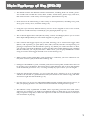
Main Features of the SPD-20
• The SPD-20 features 700 different internal instruments, including drum set sounds, percussion sounds from around the world, dance sounds, sound effects, phrase loops, and more,
that can be used in a wide variety of musical genres. (Instrument List p. 88)
• Each sound can be edited using a wide variety of sound parameters, including level, pitch,
decay, pan, velocity curve, and effect send (p. 22).
• Using the Layer function, different Velocity Curves can be assigned to each of two sounds,
and the two sounds mixed (or switched) by your playing dynamics (p. 17).
• The on-board digital effects unit (Reverb, Delay, Chorus and Flanger) allows you to set the
effect depth independently for each sound assigned to a pad (p. 28).
1
• Four external dual trigger inputs are provided, allowing you to connect kick trigger units
(KD-7s; sold separately) or pads (PD-7, PD-9, PD-5, PD-120, PD-100: sold separately), for
playing in conjunction with the SPD-20’s pads (p. 35). When you connect the PD-7 or PD-9,
you can enjoy such drum techniques as snare rim shots and cymbal choking (p. 39). With the
PD-120 connected, you can play rim shots. What’s more, you can play the SPD-20’s sounds
using an acoustic drum trigger attached to an acoustic drum (p. 45).
2
• When a hi-hat control pedal (FD-7; sold separately) is connected, you have continuous control (from closed to open) of the hi-hat sounds (p. 54).
3
• Settings for the SPD-20’s 8 pads, 4 external pads, hi-hat control pedal, and the effects unit can
be stored as one of 99 Patches. This means that a single SPD-20 is able to store and instantly
recall 99 different percussion “sets,” covering virtually any style of music you can imagine.
4
• Using the Patch Chain function, you can create and store a sequence of up to 16 Patches
which can be selected in a predetermined order (convenient for use within a song). The SPD20 can store eight such Patch Chains (p. 33).
5
• For each pad, you can set two independent MIDI transmit channels and Velocity Curves, so
that your playing dynamics can control external and internal sound generators (p. 61).
• The SPD-20 is fully expandable via MIDI, and is especially powerful when used with a
sequencer. For example, you might record SPD-20 settings as bulk data (p. 75) at the beginning of sequencer song data, or allow the sequencer to take care of Patch selection so that you
can concentrate on playing.
7
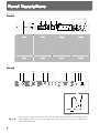
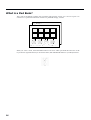
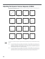
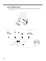
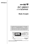
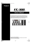
Panel Descriptions
Front
fig. (Front Panel)
1
2
3
4
5
6 7 8 9 10 1112
15
Pad 1
Pad 2
Pad 3
Pad 4
Pad 5
Pad 6
Pad 7
Pad 8
14 13
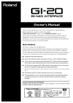
Rear
fig. (Rear Panel and Cord Hook)
16 17
18
19
20
21
22
23 24 25
Cord Hook
NOTE
8
To prevent the disruption of power to your unit (should the plug be pulled out accidentally), and to
avoid applying undue stress to the AC adaptor jack, anchor the power cord using the cord hook, as
shown in the illustration.
1
Pads 1–8
15
Play these pads to trigger the various sounds. The
pads are velocity sensitive and will respond to your
playing dynamics.
2
Patch display
These buttons are used to select Patches. In the Edit
mode they are used to modify parameter values
(p. 14).
16
This display indicates the Patch number or the value
of each parameter (p. 14).
3
PAD BANK indicator
17
5
18
Parameter List
In the Edit mode, the indicator of the selected parameter will light (p. 20). Use the [SELECT] (Parameter
Group Select) and [ ][ ] (Parameter Select) buttons to choose parameters (p. 21).
6
7
Parameter Select buttons [
][
]
In the Edit mode, use these buttons to select a parameter within the parameter group (p. 21).
8
[PATCH CHAIN] button
Use this button when setting up or playing a Patch
Chain (p. 33).
9
10
[BANK A/B] button
11
20
[LAYER] button
[EDIT] button
[FX ON/OFF] button
[ALL/ENTER] button
Use this button when setting all pads to the same
value (p. 27), when performing a copy (p. 32), or
when storing Patch Chain settings (p. 33).
2
HH CTRL/TRIG 4 jack
A hi-hat control pedal (FD-7; sold separately) can be
connected to this jack. If the external input select
switch is set to TRIG 4, an external pad can be connected to this jack (p. 35, 36).
3
21. TRIGGER INPUT 1–3 jacks
External pads etc. can be connected here (p. 37).
Use Trigger Input jack 1 and 2 to allow the play-
MEMO ing of rim shots when using a PD-120 pad (p. 38).
23. FOOT SW jack
This button turns the effects on or off (p. 28).
14
If a hi-hat control pedal (FD-7; sold separately) is connected to the hi-hat control pedal jack, set this switch
to HH CTRL (p. 40). If an external pad is connected,
set this switch to TRIG 4 (p. 37).
[COPY] button
This button switches between the Edit and Play
modes (p. 19).
13
[HH CTRL/TRIG 4] select switch
22. MIDI IN/OUT connectors
This button allows the sounds assigned to pad banks
A and B to be played together (p. 15).
12
19
Switches you between pad banks A and B
(p. 16).
Use to copy data from one Patch to another (p. 32).
1
OUTPUT (R, L/MONO) jacks
These jacks output the sound of the SPD-20. For
monaural output use the L/MONO jack (p. 12).
Parameter Group Select button [SELECT]
In the Edit mode, this button selects the desired parameter group: SOUND, MIDI, FX/PEDAL, or SYSTEM (p. 21).
PHONES jack
A pair of stereo headphones can be connected to this
jack. Even with headphones connected, the OUTPUT
jacks will still be active (p. 12).
EFFECT indicator
The LED of the selected effect will light (p. 28).
VOLUME knob
Adjusts the volume of the OUTPUT jacks and
PHONES jack (p. 13).
Indicates the selected pad bank (A or B) (p. 16).
4
PATCH/VALUE [-], [+] buttons
4
External MIDI devices can be connected here (p. 57).
A footswitch can be connected here allowing you to
change Patches by remote control. If you use a special
cable (PCS-31; sold separately) to connect two FS-5U
switches (sold separately), you can move up or down
through the Patch numbers. If you connect a DP-2
switch (sold separately), you can move up (but not
down) through the Patch numbers (p. 15).
24. AC adaptor jack
Connect the included AC adaptor here (p. 12).
Use only the included AC
adaptor. Use of any other AC
adaptor may cause damage or
malfunction.
25. POWER switch
This switch turns the unit on/off (p. 12).
9
5
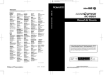
Attaching the SPD-20 to a Drum Stand
If you are attaching the unit to a cymbal stand etc. with a pipe diameter of 10.5–30 mm, use an all purpose clamp set (APC-33: sold separately).
fig.3
fig.4
NOTE
1
Using a 4 mm wrench, remove the four screws from the bottom of
the SPD-20.
2
Use the four screws you removed in step 1 to attach the stand holder to the bottom of the SPD-20.
The screws included with the APC-33 cannot be used.
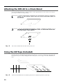
Using the Slit Tape (Included)
Place the Slit tape, included with the SPD-20, along the slits, or grooves around each of the pads. The
Slit tape allows you to clearly distinguish where each pad is, even on stage or in other darkened locations.
fig. Slit Tape
1
4
NOTE
10
2
3
5
Please note that Roland does not handle replacements or additional purchases of Slit Tape.
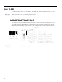
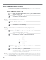
How to Restore the Factory Settings (System Initialize)
When the SPD-20 is shipped, it contains 99 Patches in memory. You can freely overwrite this data.
However, the same data is also preserved in ROM, and can be restored at any time. This procedure is
called System Initialize.
ROM
This is an abbreviation for Read Only Memory, which is a type of memory that can only be read;
modification or deletion is not possible.
The explanations in this manual assume that the SPD-20 is still in its factory initialized state. We recommend that before you begin using the unit, you perform this System Initialize operation.
NOTE
1
When you execute the System Initialize operation, all your edited data will be lost. If your SPD-20
contains important edited data, you should make a note of the settings or store the data in an external
device such as a sequencer (p. 75).
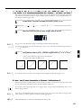
1
While holding down [
2
] and [ALL/ENTER], turn the power on.
The following display will appear.
fig.5
3
2
Press [ALL/ENTER] and the data will be initialized.
4
If you wish to quit without initializing, press any key other than [ALL/ENTER].
MEMO
It is possible to restore the factory settings of a single patch with Patch Copy (p. 32).
5
11
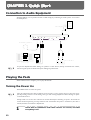
CHAPTER 1 Quick Start
Connection to Audio Equipment
With the SPD-20, you can produce realistic sounds simply by connecting an audio system. You can also
use headphones.
fig.6
AC adaptor
Stereo Headphones
LINE IN
L R
Audio Equipment
(Stereo set)
NOTE
Footswitches
To prevent malfunction and/or damage to speakers or other devices, always turn down the volume,
and turn off the power on all devices before making any connections.
Playing the Pads
When connections are complete, you can play the SPD-20.
Turning the Power On
The POWER switch is on the rear panel.
NOTE
Once the connections have been completed, turn on power to your various devices in the order specified. By turning on devices in the wrong order, you risk causing malfunction and/or damage to speakers and other devices.
Always make sure to have the volume level turned down before switching on power. Even with the
volume all the way down, you may still hear some sound when the power is switched on, but this is
normal, and does not indicate a malfunction.
1
12
Check that all connections with other devices are correct, and that
everything is off.
2
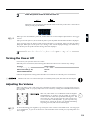
fig.7
Press the power switch to turn the unit on.
On
Off
When the power is turned on, the SPD-20 will be in the Play mode. This is the mode in
which you will play the SPD-20.
fig.8
NOTE
1
When you turn the SPD-20’s power on, it takes about one second complete adjustments to the trigger
circuits.
After you turn the power on, do not strike the pads or press the pedals until the Patch number is displayed.
If you turn the power on when a hi-hat control pedal (FD-7) is connected, make sure that the pedal is
fully open. When you turn the power on, a message “Fd7” will be displayed briefly. (For details see p.
40.) Do not press the pedal until this message has been displayed.
2
3
Turn on the other devices, but turn the power amp on last.
Turning the Power Off
3
Power down your system in the reverse order.
When the power is turned off, the following three functions will be reset to their factory settings.
Function
Local Control (p. 72)
HH Control Pedal (p. 40)
PATCH CHAIN ON/OFF
Factory setting
On
Not set
Off
4
Functions and parameter settings other than these are retained even when the power is turned off.
Whenever the unit is to remain unused for an extended period of time, disconnect the AC adaptor.
5
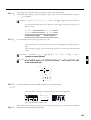
Adjusting the Volume
When you strike a pad, it will trigger the sound that has been assigned to it. Playing harder will produce a louder sound. As you play, adjust the overall volume by rotating the VOLUME knob located on
the rear panel.
fig.9
This unit, either alone or in combination with an amplifier
and headphones or speakers, may be capable of producing
sound levels that could cause permanent hearing loss. Do
not operate for a long period of time at a high volume level,
or at a level that is uncomfortable. If you experience any
hearing loss or ringing in the ears, you should immediately
stop using the unit, and consult an audiologist.
NOTE
To avoid disturbing your neighbors, try to keep the unit’s volume at reasonable levels. You may prefer
to use headphones, so you do not need to be concerned about those around you (especially when it is
late at night).
13
Selecting a Patch
When you select a Patch, the sound assigned to each pad and the settings for MIDI, effect and pedal will
all change instantly. Try each of the 99 factory-preset Patches to hear the different possibilities.
To select Patches first make sure you are in the Play mode. Then use the PATCH/VALUE [-] or [+] buttons to select Patches. The number of the selected Patch will appear in the display.
MEMO
Pressing PATCH/VALUE [+] while holding down PATCH/VALUE [-] (or vice versa) causes the
Patch numbers to change more rapidly.
fig.10
The factory patch names are listed on p. 93.
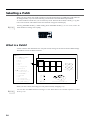
What is a Patch?
A Patch contains data determines how each pad sounds, settings for the effects and also MIDI settings.
The SPD-20 can store 99 different Patches.
fig.11
Pad 1
Sound Parameters
•
•
•
•
•
•
•
Instrument
Level
Pitch
Decay
Pan
Velocity Curve
Effect Send
MIDI Parameters
•
•
•
•
•
•
•
Transmit Channel
Note Number
Gate Time
Pan
Velocity Curve
Velocity Sensitivity
Program Change
Patch 99
•
•
Patch 1
Pad 1
Pad 2
Pad 3
Pad 4
Pad 5
Pad 6
Pad 7
Pad 8
Internal Pads 1-8
Effects
+
External Pads
1-4
Hi-Hat Control Pedal
When you select a Patch, the settings for each pad are instantly changed (p. 15).
MEMO
14
You can also use MIDI Exclusive messages to store Patch data in an external sequencer or other
device (p. 75).
Using a Footswitch to Select Patches
By using a special cable (PCS-31; sold separately) to connect two footswitches (FS-5U; sold separately)
to the FOOT SW jack, you can select Patches by remote control. When you press Footswitch 1 you will
advance to the next Patch number, and when you press Footswitch 2 you will go back to the previous
Patch number. If you connect a DP-2, you can move up (but not down) through the Patch numbers.
fig.12
Stereo
(Red)
Mono
(White)
You can make the setting with
the FS-5U polarity switch, as
shown in the figure below.
Mono
Footswitch 2
Footswitch 1
(Previous Patch)
(Next Patch)
POLALITY
1
Connect the two mono cables of the PCS-31 to the two footswitches. The plug with the white line is for
Footswitch 1, and the plug with the red line is for Footswitch 2.
MEMO
2
Connecting the model DP-2 pedal switch (sold separately) allows you to only advance the Patch numbers.
When using the footswitch as a Hold Pedal, please refer to “Using a Footwitch as a Hold Pedal” on p. 41.
3
Comparing Layered Sounds
Most of the factory-preset Patches use Layer (p. 17). Select a layered Patch and listen to the sounds of
pad banks A and B. When you select a layered Patch, both PAD BANK indicators (A and B) will light.
4
1
2
Select a Patch.
In the Play mode, press [LAYER] to turn Layer off.
5
PAD BANK indicator B will go out. Now you can play the pads to hear the sound of pad
bank A.
3
MEMO
To hear the sound of pad bank B, press [BANK A/B] so that PAD
BANK indicator B lights. Play the pads.
Each time you press [BANK A/B], PAD BANK indicators A and B will light alternately.
15
What is a Pad Bank?
The 8 pads of the SPD-20, together with 4 external pads (plus the 4 rims)—for a total of 16 pads—are
referred to as a pad bank. Each Patch contains two pad bank settings, A and B.
fig.13
Pad Bank B
Pad Bank A
Pad 1
Pad 2
Pad 3
Pad 4
Pad 5
Pad 6
Pad 7
Pad 8
4 External Pads
4 Rims
When you select a Patch, the PAD BANK indicator will show which pad bank the Patch uses. If the
Layer function (explained below) is used in that Patch, both PAD BANK indicators (A and B) will be lit.
fig.14
16
What is the Layer Function?
Layer means that two sounds are played simultaneously. The Layer setting is stored as part of each
Patch. A Patch for which Layer is enabled will simultaneously play the sounds of both pad banks (A
and B). In this case, however, you will only be able to play half as many notes simultaneously (a maximum of 7). Layering sounds can open the door to creative expression.
Ways to use the Layer function
By assigning different Instruments to pad banks A and B, and setting pad banks A and B to different
Velocity Curves (p. 24), your playing dynamics can be used to cross-fade or switch between the two
sounds.
fig.15-a
1
Velocity Mix: Playing dynamics will determine the mix of the two sounds.
Volume
Pad Bank A
Pad Bank B
+
2
Velocity
fig.15-b
Velocity Switch: Playing dynamics cause a switch between the two sounds.
Volume
Pad Bank A
3
Pad Bank B
+
4
Velocity
Velocity Crossfade: Playing dynamics produce cross-fades between the two sounds.
Pad Bank A
Volume
fig.15-c
Pad Bank B
5
+
Velocity
17
CHAPTER 2 Using the SPD-20 by Itself
About the SPD-20’s Internal Setup and Parameter Settings (Edit)
This Chapter explains the basic structure of the SPD-20 and how it functions. Before we get into details,
you should have an overall understanding of the unit.
What Kind of Instrument is the SPD-20?
The SPD-20 is an electronic percussion instrument that produces sound when its pads are struck. This
type of device is usually called a MIDI pad controller. The SPD-20 includes a sound generator (700
sounds with 16-bit dynamic range) and digital effects unit in a compact and lightweight package. By
connecting external pads or pedals (sold separately), you can obtain the same musical expressivity from
the SPD-20 as you might enjoy with an acoustic drum kit. In addition, the SPD-20 is MIDI compatible,
meaning that it can be connected to any other MIDI-compatible device (sequencer, sampler, etc.) regardless of the manufacturer. This allows you to create a very powerful music system.
Product Overview
• Self-contained compact MIDI pad controller
• 8 dynamics-sensitive pads
• 700 sounds with 16-bit dynamic range
• Built-in digital effects
• Expandable with external pads/pedals
(such as the PD-7, PD-120, KD-7, and FD-7)
• Teams up with various MIDI units
(such as sequencer, sampler, etc.)
Internal Organization
fig.16
The SPD-20 can be divided into the following sections:
Pad section
Head
Rim
Head
Rim
Head
Rim
Local Control
On/Off
FX SEND
Effects section
FX LEVEL
18
Sound Generating
section
HH CTRL
Head
Rim
Trigger Interface section
Pad section
This section has 8 velocity sensitive pads that respond to changes in your playing dynamics.
Trigger Interface section
This section sends the trigger signals (electric signals produced when you strike a pad) to the Sound
Generating section.
Sound Generating section
This section receives signals from the trigger interface or MIDI IN, and produces sound in response. The
SPD-20 contains 700 sounds and up to 14 can be played simultaneously.
1
Effects section
This section adds effects (Flanger, Chorus, Reverb, Delay) to the sound from the sound generator. You
can select from 25 effects combinations (p. 28).
2
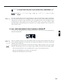
Play Mode and Edit Mode
fig.17
The SPD-20 has two modes; the Play mode and the Edit mode. Press [EDIT] to switch between them.
Play Mode
Edit Mode
3
EDIT
(the display is lit)
4
(the display is flashing)
Play Mode
In this mode you can strike the pads and select Patches. In the Play mode, the display will show the
Patch number.
5
Edit Mode
In this mode you can make settings for the various parameters. In the Edit mode, the display will show
the parameter value (which will be flashing).
MEMO
In addition to these two modes, there is another, the Advanced Edit mode, for making more detailed
settings for the Trigger parameters. (p. 48)
19
How to Edit
To modify parameter values you must be in the Edit mode. The names of all the parameters you can
modify are in the Parameter List printed on the front panel.
MEMO
“Edit” refers to the process of changing parameter values.
How to read the parameter list
The parameter list has four indicators arranged horizontally and seven indicators arranged vertically. In
the Edit mode, one of the horizontal indicators and one of the vertical indicators will always be lit. This
shows which parameter is being edited; i.e., the intersection of the indicated column and row is the currently selected parameter. The display shows the value of this parameter. To edit a particular parameter, refer to the parameter list and use the [SELECT] and [
][
] buttons to select it.
fig.18
The intersection of the
indicated column and row
Selected Parameter
Value (flashing)
INST
LEVEL
PITCH
DECAY
PAN
CURVE
FX SEND
TX CH
NOTE #
GT TIME
PAN
CURVE
SENS
PGM CHG
can be set
to each pad
MEMO
20
FX TYPE
FX TIME
FX LEVEL
PDL CTRL
PDL LEVEL
PDL CC #
can be set to
each Patch
Use PATCH/VALUE [-] or [+] to modify the parameter value.
BASIC CH
BULK DUMP
PATCH EXPAND
TRIG SENS
TRIG THRESHOLD
TRIG TYPE
TRIG CURVE
can be set to
the entire system
How to edit
1
2
Press [EDIT] to enter the Edit mode.
Select the parameter you wish to edit. Press [SELECT] to get the
appropriate indicator to light, thus selecting a column. Use [ ] or
[ ] to select the desired row, by getting the appropriate indicator
to light. (The display will show the value of the selected parameter.)
[SELECT] chooses the parameter group. The parameters of the SPD-20 are organized into
four groups: SOUND, MIDI, FX/PEDAL, and SYSTEM. With each press of [SELECT], the
indicator that lights (and the group that is selected), will be the next one in this group.
1
The [
] and [
] buttons are used to select parameters within the parameter groups.
The indicator above the currently lighted one will light when you press [
], and the one
below the one currently lighted will light when you press [
].
fig.19
SELECT
2
INST
LEVEL
PITCH
DECAY
PAN
CURVE
FX SEND
TX CH
NOTE #
GT TIME
PAN
CURVE
SENS
PGM CHG
FX TYPE
FX TIME
FX LEVEL
PDL CTRL
PDL LEVEL
PDL CC #
BASIC CH
BULK DUMP
PATCH EXPAND
TRIG SENS
TRIG THRESHOLD
TRIG TYPE
TRIG CURVE
3
4
In this illustration, the DECAY parameter in the SOUND parameter group is selected.
3
MEMO
Use PATCH/VALUE [-] or [+] to set the value. The previous value of
the parameter will be discarded. In the case of a numerical value,
PATCH/VALUE [+] increases the value, and PATCH/VALUE [-]
decreases it.
5
You can speed up the change in values by pressing [+] while holding down [-] (or vice versa).
4
5
If you wish to edit another parameter, repeat steps 2–3 as necessary.
Press [EDIT] to return to the Play mode.
The parameter list indicators will go out, and the display will once again show the Patch
number.
21
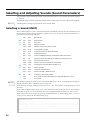
Selecting and Adjusting Sounds (Sound Parameters)
The parameters in the SOUND group (the sound parameters) allow you to modify the sound assigned
to each pad.
The SOUND group contains 7 parameters: INST, LEVEL, PITCH, DECAY, PAN, CURVE and FX SEND.
MEMO
Sound parameter settings for each pad are stored in each Patch.
Selecting a Sound (INST)
fig.96
MEMO
Each sound assigned to a pad is called an Instrument. The SPD-20 contains 700 such Instruments, and
the Instrument assign settings determine which sounds will be played. The 700 Instruments are
grouped into the following categories.
b01 – b50
Bass Drum
S01 – S86
Snare Drum
t01 – t40
Tom-tom
h01 – h33
Hi-Hat Cymbal
H01 – H17
Hi-Hat Cymbal for pedal control
C01 – C36
Crash/Ride Cymbal
L01 – L78
Latin Percussion (Cuban, Brazilian)
i01 – i33
Indian Percussion
F01 – F37
African/Middle Eastern/Australian/Other Percussion
J01 – J51
Japanese/Korean/Chinese/Southeast Asian Percussion
o01 – o24
Orchestral Percussion
M01 – M59
Melodic Percussion/Melodic Instrument
A01 – A16
Analog Percussion (CR-78, TR-808, etc.)
d01 – d43
Dance Sounds
E01 – E46
Artificial Sound Effects
n01 – n31
Natural Sounds, Human Voice
r01 – r20
Ambience, Reversed Sounds
Mut
Forces Phrase Loop Instrument to stop (MUTE). No sound
oFF
No sound
The Hi-Hat Cymbals for pedal control “instruments H01–H17” can be used effectively only when a
Hi-Hat controller (FD-7; separately sold) is used (p. 54).
If the Instrument assign setting for any Pad is set to “oFF”, there will be no sound when you strike
that Pad.
If you make the Hold Pedal settings (p. 41), then with some of the sounds, you can use the footswitch
to sustain the sound. For the instruments that can be lengthened with the footswitch, refer to p. 88.
When an Instrument is selected, by pressing PATCH/VALUE [+] while holding down [-] (or vice
versa), you can jump to the next Instrument group.
About Phrase Loop
Some Instruments are designed as Phrase Loops (p. 88).
When you select a Phrase Loop, you don’t just hear single notes; instead, a short phrase typical of
that musical genre is played. You cannot play more than one Phrase Loop on different pads. You
can layer two Phrase Loops on one pad and play them simultaneously. To force a Phrase Loop to
stop sounding, select “Mut” and strike the pad. No sound is heard from a pad that has been set for
“Mut.”
22
Adjusting the Volume (LEVEL)
This parameter determines the volume (0–15). At a setting of 0 there will be no sound.
NOTE
When FX SEND in the SOUND parameter group is set above 0, the effects sound alone will be heard
even if the LEVEL parameter is set to 0.
Adjusting the Pitch (PITCH)
This parameter determines the pitch of the Instrument (-24–+24). Each step will change the pitch by a
semitone (100 cents).
NOTE
For some Instruments, raising the pitch beyond a certain point will not be possible.
1
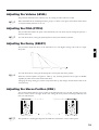
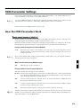
Adjusting the Decay (DECAY)
2
Level
fig.20
This parameter adjusts the decay of the Instrument (-31–+31). Higher settings will result in a longer
decay time.
3
-31
NOTE
0
31
Time
For some Instruments, raising the decay beyond a certain point will not be possible.
4
When the connected pedal is assigned to “HH” (p. 54), the decay parameter has no effect on Hi-Hat
Cymbals for pedal control (instruments H01–H17).
Changing the decay setting for a Phrase Loop Instrument (p. 88) changes the attenuation time at the
end of the loop.
Adjusting the Stereo Position (PAN)
fig.21
This parameter determines the stereo position of the Instrument (L7–Ctr–r7/rnd). A setting of L7 is far
left, Ctr is center, and r7 is far right. At the “rnd” setting, the stereo position will change randomly each
time you strike the pad.
Left Speaker
L7
NOTE
5
Right Speaker
Ctr
(Center)
r7
This parameter is meaningful only when the SPD-20 is connected to a stereo audio system.
23
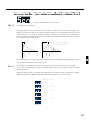
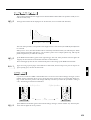
Adjusting the Dynamic Volume Response (CURVE)
This parameter determines how the Instrument volume will change in response to your playing. You
can choose from 16 response curves.
fig.22
Linear
E x p o n e nti al 1
E xponenti al 2
E xponenti al 3
E x p o n e n ti a l 4
Spline 1
S pl i ne 2
S oft 1
So ft 2
S o ft 3
S oft 4
H ard 1
H a rd 2
H a rd 3
H ard 4
C onstant
You can come up with some effective Layered sounds by combining SF (Soft) and Hd (Hard) Velocity
Curves.
24
Ex. 1:
In a layered patch, when you combine SF1 and Hd1, or SF2 and Hd2, as the Velocity Curve
settings for pad bank A and pad bank B, respectively, striking the pad lightly sounds the
Instrument of pad bank A, and the harder you hit, the louder you can make the sound of the
pad bank B Instrument become (Velocity Crossfade).
Ex. 2:
In a layered patch, when you combine SF3 and Hd3, or SF4 and Hd4, as the Velocity Curve
settings for pad bank A and pad bank B, respectively, you can switch the pad bank A and pad
bank B Instruments with the strength with which you strike the pads (Velocity Switch).
fig.23 fig.24
Pad Bank A
Pad Bank B
+
Velocity Crossfade
Soft 1
Hard 1
Pad Bank A
Pad Bank B
1
+
Velocity Switch
Soft 3
MEMO
2
Hard 3
When CSt is selected, the unit sounds at maximum volume, regardless of how hard you strike the pad.
3
Adjusting the Effects Depth (FX SEND)
This parameter determines the depth (0–15) of the effect applied to each Instrument assigned to the pad.
Higher settings will result in a deeper effect. With a setting of 0 there will be no effect. The overall
effects level for a Patch is determined by FX LEVEL in the FX/PEDAL parameter group.
4
fig.25
FX SEND
Effects section
FX LEVEL
OUTPUT
Sound Generating
section
PAN
5
L/MONO
R
LEVEL
NOTE
This FX SEND parameter will have an audible result only if the [FX ON/OFF] setting is on, and FX
LEVEL in the FX/PEDAL parameter group is set above 0.
25
How to Edit Sound Parameters
It is not possible to simultaneously edit the sound parameters of pad banks A and B. Use [BANK A/B]
to switch between the two pad banks, and edit each bank separately.
Editing a sound parameter
1
2
MEMO
Press [EDIT] to enter the Edit mode.
Selecting and changing parameters is called editing.
3
4
MEMO
In the Play mode, use the PATCH/VALUE [-] or [+] buttons to select
the Patch (1–99) to edit.
Strike the pad you wish to edit.
Turn Layer on or off if necessary.
You can have only one of the Pad Bank Instruments sound by setting Layer to OFF.
5
Press [BANK A/B] to select the bank you wish to edit.
The selected PAD BANK indicator will be flashing.
fig.26
6
Press [SELECT] to select the SOUND parameter group.
INST
LEVEL
PITCH
DECAY
PAN
CURVE
FX SEND
7
8
Press [
] or [
] to select the parameter to be edited.
Use PATCH/VALUE [-] or [+] to set the value.
For a numerical parameter, pressing PATCH/VALUE [-] will decrease the value, and
pressing PATCH/VALUE [+] will increase the value.
MEMO
26
Pressing PATCH/VALUE [+] while holding down PATCH/VALUE [-] (or vice versa) makes this
change more rapidly. However, when selecting a Parameter Group Instrument (INST), when you
press PATCH/VALUE [+] while holding down PATCH/VALUE [-] (or vice versa), you jump to the
next Instrument group.
9
10
MEMO
To edit the other pad bank of the layered sound, repeat steps 5–8.
When you finish making settings, press [EDIT] to return to the Play
mode.
By using a special cable (PCS-31; sold separately) to connect two footswitches (FS-5U; sold separately) to the FOOT SW jack, you can change parameter values by remote control. While in Edit Mode,
when you press Footswitch 1 you will advance to the next higher parameter value, and when you press
Footswitch 2 you will go down to the next lower parameter value (p. 15). If you connect a single
footswitch (DP-2; sold separately) you can only move up to a higher parameter value, not down to a
lower parameter value.
1
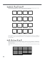
Setting all pads to the same parameter value
If you press [ALL/ENTER] after step 8, the displayed parameter value will be set for all pads of the currently selected pad bank.
2
fig.27
MEMO
3
If you are making settings for one of the SPD-20’s pads, the settings will be applied to all 8 pads. If
you are making settings for an external pad, the settings will be applied to all 4 of the external pads,
and all 4 of the external rims.
By assigning the same Instrument to all the pads and setting a different pitch for each, you can play
melodies. The following procedure is an example using a melodic percussion Instrument (M01–M59).
4
1. Set the INST parameter in the SOUND parameter group to the desired Instrument.
2. Press [ALL/ENTER] to set all pads to the same sound.
3. Adjust the PITCH parameter for each pad.
5
27
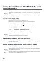
Adding Reverberation and Other Effects to the Sound
(Effect Parameters)
The SPD-20 has four on-board effects: Reverb, Delay, Chorus, and Flanger. There are three effects parameters: FX TYPE, FX TIME and FX LEVEL.
MEMO
Effects settings are stored independently for each Patch, so you can set up the ideal effects for each
Patch.
Chapter 5 includes a section on “Taking Advantage of the On-board Effects” (p. 79), and we suggest
that you read this as well.
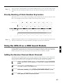
Select an Effect (FX TYPE)
This parameter selects one of the 25 effects combinations (1–25).
fig.27-a
MEMO
The Effect Indicator for the selected effect type will light to show the effect being used.
Effect Type
Explanation
1–10
Reverb sound
Adds reverberation to the sound
11–14
Chorus sound
Adds breadth to the sound
15–17
Flanger sound
Applies undulations to the sound
18–25
Delay sound
Adds an echo-like effect
For details on each effect type, refer to the page 79.
The effects are toggled on/off with each press of [FX ON/OFF].
Setting Effect Duration and Rate (FX TIME)
This sets the duration of reverberation, or the modulation rate (1–32). The higher the value, the longer
the reverb duration, or the higher the modulation rate. The result will be different depending on the
type of effect. Refer to page 79.
Adjust the Effect Depth for the Entire Patch (FX LEVEL)
This parameter corresponds to the effect return level on a mixer, and higher settings will result in a
deeper effect (0–15). At a value of 0 there will be no effect.
MEMO
The depth of the effect applied to each Instrument (assigned to a pad) is determined by FX SEND in
the SOUND parameter group. (p. 25)
NOTE
This effect level parameter will have an audible result only if the [FX ON/OFF] setting is on, and if
the Instrument parameter FX SEND for a pad is set above 0.
28
How to Edit Effect Parameters
fig.28
1
2
3
4
5
6
7
In the Play mode, use PATCH/VALUE [-] or [+] to select a Patch
(1–99).
Press [EDIT] to enter the Edit mode.
Press [SELECT] to select the FX/PEDAL parameter group (p. 21).
Press [
SOUND
MIDI
FX/PEDAL SYSTEM
INST
LEVEL
PITCH
DECAY
PAN
CURVE
FX SEND
TX CH
NOTE #
GT TIME
PAN
CURVE
SENS
PGM CHG
FX TYPE
FX TIME
FX LEVEL
PDL CTRL
PDL LEVEL
PDL CC #
] or [
1
BASIC CH
BULK DUMP
PATCH EXPAND
TRIG SENS
TRIG THRESHOLD
TRIG TYPE
TRIG CURVE
2
] to select the effect parameter you wish to edit.
3
Use PATCH/VALUE [-] or [+] to set the value.
Repeat steps 3–5 to finish making the effect settings for the Patch.
4
If you wish to adjust the effect depth independently for each pad,
make the appropriate settings for the FX SEND in the SOUND parameter group for each pad (p. 25).
5
29
Adjusting the Pad Sensitivity (TRIG SENS)
By adjusting the TRIG SENS in the SYSTEM parameter group you can adjust the sensitivity of the pad
when it is struck (the range of adjustment is 1–16). Higher settings result in higher sensitivity, so that
the pad will produce a loud volume even when struck softly. This parameter applies to all 8 pads.
NOTE
Factory Trigger Sensitivity (TRIG SENS) settings for the internal pad reflect the average user´s preferences. If these settings produce good results for you, then there is no need to change the Trigger
Sensitivity values.
MEMO
This parameter is set for all 8 pads, i.e., the same value applies to all pads. However, this parameter
can be set independently for each connected external pad.
Trigger Sensitivity (TRIG SENS) settings are common to all patches.
fig.29
MEMO
1
2
3
Press [EDIT] to enter the Edit mode.
4
Strike one of the 8 pads.
Press [SELECT] to select the SYSTEM parameter group.
Use [
] or [
] to select TRIG SENS.
When you strike the pad, the strength with which the pad is struck (velocity) is shown in the display
on a six-level scale. Striking the pad forcefully sets velocity at a value of 127.
fig.95
Strength
of Striking
Velocity
Hard
127
100–126
75–99
50–74
25–49
Soft
5
30
1–24
Use PATCH/VALUE [-] or [+] to set the value.
Setting the Pad’s Minimum Level (TRIG THRESHOLD)
Threshold Level
fig.30
By adjusting the TRIG THRESHOLD in the SYSTEM parameter group you can have a pad produce a
trigger signal only when struck with more than a certain level of force (a “threshold”). This can be used
to prevent a pad from sounding in response to extraneous vibrations from another pad. However, if
you strike the pad with a force less than the Trigger Threshold, it will not sound. In the diagram below,
the pad will sound for 2, but not for 1 or 3. This parameter can be set over a range of 0–15.
1
0
1
2
3
NOTE
Factory Trigger Threshold (TRIG THRESHOLD) settings for the internal pad reflect the average
user´s preferences. If these settings produce good results for you, then there is no need to change the
Trigger Sensitivity values.
MEMO
This parameter is set for all 8 pads, i.e., the same value applies to all pads. However, this parameter
can be set independently for each connected external pad.
2
3
Trigger Threshold (TRIG THRESHOLD) settings are common to all patches.
fig.31
1
2
In the Edit mode, select the SYSTEM parameter group (p. 21).
Use [
] or [
4
] to select TRIG THRESHOLD.
5
3
4
MEMO
Strike one of the 8 pads.
Use PATCH/VALUE [-] or [+] to set the value.
For information on editing external Pad Trigger Parameters, please refer to p. 42.
31
Copying a Patch (COPY)
fig.29-1
This operation copies Patch settings to another Patch. If you need another Patch that is only slightly different from an existing one, copy that Patch and then make the changes that you need.
Copy source
Copy destination
Patch
Patch
User Patch U1-U99
Preset Patch P1-P99
MEMO
User Patch U1-U99
When you execute COPY, the contents of the copy destination patch are rewritten.
1
In the Play mode, use PATCH/VALUE [-] or [+] to select the copy destination Patch (1–99).
When you execute COPY, the data is overwritten in this patch.
fig.32
2
3
Press [EDIT] to enter the Edit mode.
4
Use PATCH/VALUE [-] or [+] to select the copy source Patch.
Press [COPY].
The copy source Patch can be selected from user Patches (U1–U99) or factorypreset Patches (P1–P99).
MEMO
fig.32-a
MEMO
32
Play the pads to check the selected copy source Patch.
To quit without copying, press [COPY].
5
Press [ALL/ENTER] and the Patch will be copied.
6
Press [EDIT] once again to return to the Play mode.
The external pad’s SOUND parameter, MIDI parameter, and FX/PEDAL settings are copied simultaneously.
Setting Up Your Own Patch Sequences (Patch Chain)
What is a Patch Chain?
fig.33
A Patch Chain is a sequence (that you create) of up to 16 Patches. The SPD-20 can store 8 of these Patch
Chains (A, b, C, d, e, F, G, H.)
Step 1
Step 2
Step 3
Step 4
Step 5
•••
•••
Step 16
Patch Chain A
•••
Patch Chain B
•••
Patch Chain H
1
By setting up a Patch Chain that contains all the Patches needed for a stage set or a song, you can quickly and easily access the Patches you need.
Setting up a Patch Chain
fig.36
1
2
In the Edit mode, press [PATCH CHAIN] to select a Chain (A, b, C, d,
e, F, G, H).
A
B
C
D
E
F
G
H
3
4
2
MEMO
You can also select Patch numbers using a footswitch connected to the FOOT SW jack.
3
4
MEMO
fig.35
Use the PATCH/VALUE [-] or [+] buttons to select the Patch number
(1–99).
5
Press [ALL/ENTER].
Repeat steps 2–3 to create a Chain of Patches.
Each Chain can consist of up to 16 Patches. If you attempt to specify a 17th Patch, the display will
show “FUL.”
5
When you are finished, press [ALL/ENTER].
33
NOTE
If you press [PATCH CHAIN] to select another Chain before pressing [ALL/ENTER], the Patch
Chain settings you just made will be lost.
6
7
If you wish, you may make settings for another Patch Chain.
When you finish making Patch Chain settings, press [EDIT] to return
to the Play mode.
Using a Patch Chain to Select Patches
Here’s how to step through the Patches in a Patch Chain.
fig.36
NOTE
1
A Patch Chain which does not contain any data will not be displayed in the Play mode.
2
MEMO
In the Play mode, press [PATCH CHAIN] to select the Patch Chain
you wish to use (A, b, C, d, e, F, G,H).
Each time you press PATCH/VALUE [-] or [+]the next Patch in the
Chain will be selected.
After the last Patch in the Chain, you will return to the first Patch.
A footswitch connected to the FOOT SW jack can also be used to select Patches.
3
Press [PATCH CHAIN] several times to return to the Play mode.
Erasing a Patch Chain
Here’s how to erase the current Patch Chain settings.
fig.37
NOTE
34
1
2
Press [EDIT] to enter the Edit mode.
3
Press [EDIT] once again to return to the Play mode.
Use [PATCH CHAIN] to select a Patch Chain, and press [ALL/ENTER]
to erase it. The following display will appear.
After all chains are cleared, the Patch Chain cannot be used, even if you press [PATCH CHAIN] in
the Play mode.
CHAPTER 3 Connecting External Pads or Pedals
You can add external pads to the SPD-20. Furthermore, you can connect a hi-hat control pedal (FD-7;
sold separately) to control the opening and closing of the hi-hat.
Connecting External Pads or Hi-Hat Control Pedal
Connecting External Pads or the Special Pedal
Example 1: Percussion Set
The SPD-20 should be mounted on a stand. A commercially available cymbal or tom-tom stand works
well for this.
1
fig.38
2
3
4
4 Pads (PD-7)
5
Set to TRIG 4
HH CTRL
/TRIG 4
TRIGGER INPUT (1–3)
35
Example 2: Full Set Kit
If you wish to connect a hi-hat control pedal (FD-7; sold separately) to the HH CTRL/TRIG 4 jack, set
the [HH CTRL/TRIG 4] select switch (p. 40) to HH CTRL. If you wish to connect an external pad, set the
switch to TRIG 4.
fig.39
Crash Splash Ride China
Tom1 Tom2 Tom3 Tom4
Hi-Hat
Snare
Roland
Kick
Hi-Hat Control Pedal
Hi-Hat Control Pedal (FD-7)
Pad (PD-120)
Kick Trigger Unit (KD-7)
+ Kick Pedal
Pad (PD-7)
TRIG 3
HH CTRL/TRIG 4
HH CTRL
/TRIG 4
36
TRIG 2
TRIG 1
TRIGGER INPUT (1–3)
Set to HH CTRL
Precautions When Connecting a External Pad
fig.40
The external pad and Kick Trigger Unit are
connected to the Trigger Input jacks 1, 2, and
3, or the HH CTRL/TRIG 4 jack. (However,
in this case, the Trigger Input switch is set to
TRIG 4.)
NOTE
PD-7
PD-120
You may hear a brief sound when you change the position of the switch. This is normal, and should
not be a cause for concern.
To perform with even greater expression, we recommend the use of the following specialized pads from
Roland.
1
PD-7, PD-9, PD-5, PD-120, PD-100, KD-7 (Kick Trigger Unit)
When you use these pads, it is necessary to set the pad type with the TRIGGER parameter TRIG TYPE
(p. 45).
NOTE
Use a mono cable when connecting pads from other manufacturers.
2
When using a PD-7, PD-9 and KD-7, set the Polarity Switch on the pad to the “-” (negative) side,
and make connections using the cable included with the pad or Kick Trigger Unit.
You may hear a brief sound when you change the position of this switch. This is normal, and should
not be a cause for concern.
MEMO
The four Trigger Input jacks provided with the SPD-20 are already Dual Trigger Type. This is to
allow processing of two types of signals, for when you strike the head and for rim shots, when you connect a PD-7 or PD-9.
NOTE
You can play rim shots with the PD-120 only by using Trigger Input jacks 1 and 2 (p. 38).
3
4
Precautions when connecting a Kick pedal (Kick Trigger Unit)
fig.41
When using a kick pedal, a specialized Kick Trigger Unit (KD-7; sold separately) is necessary.
A connecting cable and beater are included
with the KD-7, and you may use a favorite bass
drum pedal to control the SPD-20 sounds. Set
the Polarity Switch on the KD-7 to the “-”(negative) position, then connect to an TRIGGER
INPUT jack (1–3), or to the HH CTRL/TRIG 4
jack. (However, in the later case, be sure to set
the External input select switch to TRIG 4.)
5
Kick Trigger Unit (KD-7)
+ Kick Pedal
By connecting two sets of units and pedals, you can use dual bass drum techniques. There are two
ways to do this. You can use the mix in jack of one KD-7 and connect the two sets in serial to one SPD20 input, or you can connect each KD-7 to its own SPD-20 Trigger input. The first method uses only one
SPD-20 TRIGGER INPUT, and the second method uses two SPD-20 TRIGGER INPUTs. However, the
second method allows you to control two different Instruments, so that you can assign different-sounding Kick Drums to each side, and change the pitch and Pan settings for a more expressive sound.
NOTE
When connecting two KD-7s with the KD-7’s Mix In jack, the Kick Trigger signal is slightly weakened. In such cases, when connecting the KD-7 set the Trigger Input Trigger Sensitivity (TRIG
SENS, p. 43) slightly higher.
37
Using a Footswitch Instead of a Kick Pedal
Even without a kick pedal, you can play Instruments by connecting a Pedal Switch (DP-2; sold separately) to Trigger Input jack 1. The pedal switch will yield one consistent level, regardless of how hard you
hit the pedal. The level is set with a combination of two parameters. Set the Trigger Sensitivity (TRIG
SENS) to have enough signal, then you may reduce the volume level with the Sound parameter level
(LEVEL). Additionally, set the Trigger Threshold (THRESHOLD) between 6 and 8. Setting the Trigger
Threshold value any lower than this causes the pedal to trigger sounds even when you remove your
foot; setting it any higher prevents any triggering.
When triggering a sound module via MIDI, you can set the volume using MIDI parameter SENS.
NOTE
When using a Pedal Switch (DP-2; sold separately) to play Instruments, use only Trigger Input jack 1.
Precautions When Connecting the PD-100 or PD-120
Use the PD-120/PD-100 only after thoroughly reading the manuals provided with those models.
fig.42
When using models PD-120/PD-100, set the pad type
(120, 100) with the TRIGGER parameter TRIG TYPE (p.
45). With the PD-120, setting the Trigger Type makes it
possible for you to play rim shots.
You can play rim shots with the PD-120 only by using
Trigger Input jacks 1 and 2.
MEMO
With the PD-7 and PD-9, you can play rim shots using any of the Trigger Inputs.
NOTE
The sound does not change, regardless of where you strike the head.
If the PD-120 does not play rim shots, check the following items.
➜ The PD-120’s rim shot trigger characteristics differ from those of the PD-7 (or PD-9). Rim shots
are detected by setting the Trigger Type to the PD-120.
➜ Is it connected to Trigger Input 1 or 2?
Rim shots on the PD-120 are detected only through Trigger Input 1 and 2.
➜ Is the PD-120 connected with the stereo cable provided?
When the PD-120 is connected with a mono cable, rim shots are not detected.
➜ Please strike the rim close to where the PD-120’s jack is located (p. 39).
MEMO
When using the PD-120 as a snare, please play with the unit set up on a snare stand.
NOTE
Do not play the PD-120 or PD-100 when the head is loose. Striking the head when it is loose
not only causes sounds to be played incorrectly, but may also result in damage to the internal sensors.
Furthermore, you’ll get better performance if the head is on the stiff side.
38
How to Use the Rim Shot and Cymbal Choke Playing Techniques
If a PD-7 or PD-9 is connected, you will be able to use Rim Shot and Cymbal Choke playing technique.
If a PD-120 is connected, you will be able to use Rim Shot playing technique.
Rim Shot
By playing Rim Shot, you can play two types of sound from one pad. This can be done with a PD-7, PD9, PD-120.
MEMO
At the time the unit was shipped from the factory, the Snare Drum Rim Shot Instrument was set to
Patch 1 Trigger Input 2; confirm this by actually striking the pad.
Normal shot: Strike only the head (center)
fig.43
1
Rim shot: Strike both the head and the rim (perimeter) simultaneously.
Pad
Pad
Rim of the Pad
2
Center of Pad
NOTE
Rim Shot
When playing rim shots, striking only the rim does not produce a solid rim shot sound. Be sure to
strike both the head and rim at the same time. With rim shots how hard the drum is struck is detected
in the head portion.
3
fig.44
NOTE
MEMO
rim shots can be played on the PD-120 only through
Trigger Input 1 and 2.
With the SPD-20, you can choose two separate MIDI
sound modules for a dual trigger pad, i.e. send the “head
only” to MIDI channel 10, and the “rim” to MIDI channel 11. This allows you to control instruments from two
MIDI systems with one PD-7, PD-9, or PD-120 (p. 66).
HEAD MADE BY REMO U.S.A.
When you play rim shots on the PD-120, with the pad
OUTPUT jack facing toward you as shown in the figure,
strike the rim within the range shown. By making rim
shots outside this range you will not be able to achieve a
reliable rim shot sound.
4
OUTPUT
Jack
Range within
which rim shots
can be made
5
Toward the player
Cymbal Choke
fig.45
With the PD-7 and PD-9, physically grasping the rim of the pad just after the pad is struck stops the
sound as it is made. This allows you to make the same sound you get when you stop the cymbal from
sounding with your hand just after striking it.
39
Precautions When Connecting a Hi-Hat Control Pedal
fig.46
Connect the hi-hat control pedal (FD-7; sold separately) to the HH CTRL/TRIG 4 jack, and set the
Trigger input switch to HH CTRL. When using an FD-7 you will be able to control various Instrument
parameters in real time (p. 54).
FD-7
How to set the hi-hat control pedal for the best possible performance results
1
2
NOTE
NOTE
Make sure that the pedal is fully open.
If the pedal is depressed, settings will not be made correctly.
3
fig. 47
Using the cable included with the FD-7, connect the FD-7 to the HH
CTRL/TRIG 4 jack.
Move the external input select switch to TRIG 4 and then move it
back to HH CTRL. When the switch is moved back to HH CTRL the
following display will appear. This indicates that the FD-7 has been
“recognized” by the SPD-20 and will now function correctly.
You may hear a brief sound when you change the position of this switch. This is normal, and should
not be a cause for concern.
Be very careful not to depress the pedal until the above message is displayed.
The appropriate settings will be made automatically and the same message will be displayed whenever
the power is turned on with the FD-7 already plugged in.
Using a Footswitch in Place of the Hi-Hat Pedal
In place of a hi-hat control pedal, you can also control the hi-hat with a footswitch (DP-2 Pedal Switch;
sold separately) connected to the HH CTRL/TRIG 4 jack. However, with this arrangement, techniques
such as half open cannot be played. Just as with the hi-hat control pedal, when using the footswitch, it
is necessary to have the pedal recognized using the previously mentioned procedure. When the pedal
switch is properly recognized, “dP2” appears in the display.
40
Using a Footswitch as a Hold Pedal
A footswitch (DP-2/FS-5U; sold separately) connected to the FOOT SW jack can be used as a hold (sustain) pedal to control specified Instruments and external MIDI sound modules. When you depress the
pedal, a Control Change message (Hold) will be transmitted, instructing the MIDI sound modules to
continue sounding the notes that are currently being played.
fig.48
If you turn the SPD-20 on while the footswitch is depressed, the following message will scroll across the
display and the footswitch will act as a hold pedal.
If you are using an FS-5U, Footswitch 1 with PCS-31 will act as the hold pedal, and Footswitch 2 will
increase the Patch number.
NOTE
MEMO
NOTE
1
The SPD-20’s display can only show 3 characters at once. To “scroll” means that the characters automatically move across the display to show a longer message. The SPD-20 will sometimes scroll error
messages or other helpful information (p. 87).
Hold messages will be transmitted on the channel specified by the Basic Channel.
2
There are specific Instruments in the internal sound generator that can also be held with a footswitch
(p. 88).
This may not work properly for some MIDI sound modules or some sounds.
3
When using the footswitch as a Patch Shift Pedal (p. 15), first turn off the power to the unit, then with
the footswitch depressed, turn the power back on. The following message is displayed, and the
footswitch is set to function as a Patch Shift Pedal.
4
The footswitch can function as a “Patch Shift Pedal” or a “Hold Pedal.”
Each time the power is turned on with the footswitch in the depressed position, the function is switched
between “Patch Shift Pedal” and “Hold Pedal.” The footswitch setting is set at the factory to “Patch
Shift Pedal.”
5
41
Settings for External Pads or Kick Trigger Units
Setting External Pad Tone and MIDI Parameters
Sound and MIDI parameters can be set for external pads or Kick Trigger Units (connected to the TRIG
INPUT jacks) in the same way as for the on-board pads.
If a PD-7, PD-9, PD-120 is connected, each parameter can be set independently for the head and rim.
The method for setting external pad tones is the same as that for internal pads. Make settings after
referring to “Selecting and Adjusting Sounds (Sound Parameters)” (p. 22). With external pads, you can
make settings for both the head and the rim. To make settings for the head, strike only the head. To
make settings for the rim, simultaneously strike the rim and head. (Rim settings apply only to the PD-7,
PD-9, and PD-120. However, the rim for the PD-120 can only be used with Trigger Input 1 and 2.)
Press the connected pedal when making the Kick Trigger Unit’s tone settings.
Except for the option of making rim settings, MIDI parameter settings for external pads are made the
same way as those for internal heads. Make settings after referring to “MIDI Parameter Settings” (p.
61).
NOTE
It is better not to set and layer two different tones and Velocity Curves using the rim’s Pad Bank,
since the relative strength is difficult to control precisely.
How to Edit the Trigger Parameters
You can set the sensitivity and make other settings for external pads (TRIGGER parameters). There are
four types of TRIGGER parameters available (TRIG SENS, TRIG THRESHOLD, TRIG TYPE, and TRIG
CURVE).
Settings for some of these parameters can control both internal and external pads; others can control the
external pads only.
NOTE
42
Parameter
Internal Pad
External Pad (4 Independent)
TRIG SENS
Common to 8 Pads
OK
TRIG THRESHOLD
Common to 8 Pads
OK
TRIG TYPE
No
OK
TRIG CURVE
No
OK
External and internal pads have shared TRIGGER parameter settings.
Adjusting the Sensitivity of a Pad or Kick Trigger Unit (TRIG SENS)
This parameter adjusts the sensitivity of a pad or Kick Trigger Unit. Higher values will result in higher
sensitivity (setting range: 1–16). When external pads are connected, you should adjust the relative sensitivity between the external and on-board pads so as to provide a balanced feel for the entire drum kit.
fig.49
1
2
In the Edit mode, select the SYSTEM parameter group (p. 21).
Use [
] or [
] to select TRIG SENS.
1
3
MEMO
Strike the pad (or depress the Kick Trigger Unit) you wish to edit.
2
When you strike the pad, the strength with which the pad is struck (velocity) is shown in the display
in six levels. Striking the pad hard sets velocity at a value of 127.
fig.95
Strength
of Striking
Velocity
Hard
127
3
100–126
75–99
4
50–74
25–49
Soft
4
1–24
5
Use PATCH/VALUE [-] or [+] to set the value.
About the PD-120’s Rim Sensitivity
Available only when making Trigger Type settings to the PD-120, you can set the Rim Sensitivity in
Advanced Edit mode (p. 53).
43
Setting Minimum Levels for the Pads (TRIG THRESHOLD)
Threshold Level
fig.50
By setting this parameter, you can make the pad respond with a trigger signal only when it is struck
with a force above a threshold level. This allows you to prevent the pad from picking up extraneous
vibrations from neighboring pads. If the striking force is less than the threshold, the pad will not sound.
In the following diagram, the statement like “2” of the examples will produce sound(setting range:
0–15.)
0
1
NOTE
2
3
To have the unit sound even when struck lightly, set the TRIGGER THRESHOLD as low as possible
without triggering other connected pads.
Settings for the internal pads reflect the average user´s preferences. If these settings produce good
results for you, there is no need to change these values.
fig.51
MEMO
1
2
In the Edit mode, select the SYSTEM parameter group (p. 21).
3
Strike the pad (or depress the Kick Trigger Unit) you wish to edit.
44
] or [
] to select TRIG THRESHOLD.
Rim and head feature shared TRIG THRESHOLD settings for all pads (PD-7/9, PD-120).
4
MEMO
Use [
Use PATCH/VALUE [-] or [+] to set the value.
When the vibration from striking one external pad causes the Instrument of another pad to play, set
Crosstalk Cancel (p. 53).
Selecting Types for External Pads (TRIG TYPE)
The SPD-20’s Trigger Inputs allow you to connect and play using a variety of pad types. While the trigger
signal output from a pad can have a variety of characteristics depending on the type of pad, you can make
sure the trigger signal is read correctly by setting the Trigger Type. In addition, when connecting the PD-120
or other pad models, setting the Trigger Type makes it possible to play rim shots on the PD-120 (p. 39). The
Trigger Type is set not only for different drum pad types, but for different acoustic drum triggers as well.
Acoustic Drum Triggers
These are pickups that are attached to acoustic drums. The strength with which the drum is struck
is output as a trigger signal, allowing you to play sound modules with Trigger Inputs such as the
SPD-20’s.
fig.53
1
2
3
1
In the Edit mode, select the SYSTEM parameter group (p. 21).
Use [
] or [
] to select TRIG TYPE.
2
Strike the External pad (or depress the Kick Trigger Unit) you wish
to edit.
3
MEMO
Trigger Type rim and head settings are shared for all pads (PD-7/9, PD-120).
NOTE
You cannot make settings for the internal pads. If you try to select the internal head by striking it,
“
” is displayed.
4
4
Use PATCH/VALUE [-] or [+] to set the value.
Pad Trigger Types
Displayed
5
Description
fig.54
For the PD-5
For the PD-7, standard drum pads, other manufacturers’ pads
For the PD-9, low crosstalk (p. 53) pads
For the PD-100
For the PD-120
For other makers’ pads (See Note)
For other makers’ pads (See Note)
For the KD-7, standard kick pads, other manufacturers’ pads
For other manufacturers’ kick pads (see Note)
For other manufacturers’ kick Pads (see Note)
45
(Note) This type of Trigger (TRIG TYPE) is for drum pads whose output of the Trigger signal waveform’s attack is slow. In order to reliably detect the strength with which the pad is struck, the
time set for detection of the trigger (Scan Time; p. 51) is as slow as 1–2 msec. When using other
manufacturers’ pads, if while playing with the Trigger Type set to “Pd7” you notice the sound
strength or dynamics are unstable, you should reset the Trigger Type to “P1” or “P2.”
For faster sound expression, set to “P1” or “P2” (“K1” or “K2”).
Acoustic Drum Trigger Types
Displayed
Description
fig.54
For kick drums (bass drums)
For snare drums
For toms
For floor toms, toms with 15-inch or bigger heads
Trigger Type Internal Settings (Advanced TRIGGER Parameters)
When you make settings for the Trigger Type, a number of internal parameters that do not appear
on the panel are set automatically. These parameters are known as Advanced TRIGGER parameters. Normally, no detailed settings are necessary to match the selected Trigger Type, but when
you get poor sound, even having set the Trigger Type, or when using pads or acoustic drum triggers not covered by a particular Trigger Type, then set the Advanced TRIGGER parameters as
needed (p. 48).
Advanced TRIGGER Parameter
Description
Scan Time
Sets the time for detecting the trigger signal
Retrigger Cancel
Detects the attenuation of the trigger signal and cancels subsequent incorrect triggering
Mask Time
Cancels secondary sounding of the kick pad and other pads
Crosstalk Cancel
Cancels triggering caused by vibration from other pads
Rim Sensitivity
Adjusts the PD-120’s Rim Sensitivity
For more detailed information, refer to (p. 48).
46
Setting How the Strength with Which External Pads Are Struck Changes the Volume (TRIG CURVE)
With some external pads and acoustic drum triggers, the relationship between the strength with which
you strike the pad and the changes in volume output signal is unnatural. To get natural-sounding volume changes, set the Trigger Curve.
fig. 55
MEMO
1
2
3
In Edit mode, select the SYSTEM parameter group (p. 21).
Press [
] or [
] to select the TRIG CURVE.
Strike the external pad (or Kick Trigger Unit) to be set.
1
2
Trigger Curve rim and head settings are shared for all pads (PD-7/9, PD-120).
You cannot make settings for the internal pads. If you try to select the internal head by striking it,
“
” is displayed.
4
Using PATCH/VALUE [+] or [-], set the Trigger Curve (-2, -1, 0, 1, or 2).
3
Values correspond to the Trigger Curves shown below.
“0” denotes the standard Trigger Curve.
fig. 56
Level
4
-2 Striking Force
MEMO
-1
0 (Standard)
1
2
5
To make this setting correctly, set the Trigger Sensitivity before setting the Trigger Curve.
Setting the Same Parameter Values to All Pads
When you press [ALL/ENTER] while in Edit mode, the parameter values that are set in an external pad
are set to all external pads that are in the selected pad bank at that time.
For example, with Trigger Type Pd7 set to Trigger Input 1, by pressing [ALL/ENTER], Pd7 is set to
all four Trigger Inputs.
MEMO
If you press [ALL/ENTER] when setting the Trigger Type, the current pad’s Advance Trigger parameter settings (p. 48) are applied to all of the other Trigger Inputs.
NOTE
[ALL/ENTER] does not function in Advanced Edit mode (p. 48).
47
Setting Parameters for Reliable Performance using Acoustic Drum
Triggers and Other Manufacturers’ Pads (Advanced Trigger Parameters)
Sometimes, when you use the SPD-20 with an acoustic drum trigger or a pad from another manufacturer,
setting only the Trigger Type may result in poor sound or mistakenly played sounds. In such cases, by setting the Advanced Trigger Parameters, you can make more detailed trigger parameter settings.
NOTE
Advanced Trigger Parameters are set automatically when the Trigger Type is set. Normally, when
you set the Trigger Type, no setting of the Advanced Trigger Parameters is necessary.
The five Advanced Trigger Parameters are as follows:
Scan Time
Sets the time for detecting the trigger signal
Retrigger Cancel
Detects the attenuation of the trigger signal, and prevents subsequent
incorrect triggering
Mask Time
Prevents secondary sounding of the kick pad and other pads
Crosstalk Cancel
Prevents triggering caused by vibration from other pads
Rim Sensitivity
Adjusts the sensitivity of the PD-120´s rim
How to Set Advanced Trigger Parameters
The process of making settings for the Advanced Trigger Parameters differs from that when making
other settings. Special procedures are required to set the parameters in Advanced Edit mode.
NOTE
The Advanced Trigger Parameters cannot be found in the Parameter List on the front panel.
You cannot make Advanced Trigger Parameter settings for internal pads.
There are three modes
Play mode:
The unit is played in this mode.
Edit mode:
Status in which settings are made for the parameters from the parameter
list.
Advanced Edit mode:
In this mode, settings can be made for the Advanced Trigger Parameters,
which are not included in the parameter list.
First, set the Trigger Type. When you set the Trigger Type, the most suitable Advanced Trigger
Parameters values are set automatically.
NOTE
fig. 57
48
If, after having set the Advanced Trigger Parameters, you then change the Trigger Type setting, the
Advanced Trigger Parameter settings revert to the initial values for that Trigger Type.
1
2
3
In Edit mode, select the SYSTEM parameter group (p. 21).
Press [
] or [
] to select the TRIG TYPE.
Strike the external pad (or drum pad) to be set.
MEMO
Trigger Type rim and head settings are shared for all pads (PD-7/9, PD-120).
You cannot make settings for the internal pads. If you try to select the internal head by striking it,
“
” is displayed.
4
Using PATCH/VALUE [+] or [-], set the Trigger Type.
If you don’t find the settings most suitable for your Trigger Type, then set the type you
think is closest.
MEMO
Drum Pad:
Pd7, P 1, P 2
Kick Pad:
Kd7, K 1, K 2
Acoustic Drum Trigger:
KiK, Snr, toM, FLr
1
For descriptions of each of the Trigger Types, see p. 45.
Up to this point, the procedure has been the same as in making normal Trigger Type settings.
2
After setting the Trigger Type, the following operation is used to enter Advanced Edit
mode.
fig. 58
5
6
Confirm that Trigger Type (TRIG TYPE) in the SYSTEM parameter
group has been selected.
Hold down [EDIT] for several seconds.
Advanced Edit mode.
3
This takes you into
(Flashing)
4
5
MEMO
fig.59
In Advanced Edit mode, the SYSTEM Parameter Group indicator flashes.
One second after “Scn” appears in the display, the value is then displayed.
About one
second later
This is the Scan Time settings screen.
NOTE
If the TRIG TYPE settings screen does not come up, consequently, you can not call up the Advanced
Edit Mode screens by holding down [EDIT].
49
7
fig. 60
MEMO
Scn Scan Time
rEt Retrigger Cancel
CrS Cross Talk Cancel
riM Rim Sensitivity
MSK Mask Time
Refer to p. 51 for descriptions of how each of the parameters works.
8
MEMO
Press [ ] or [ ] to select the Advanced Trigger Parameter to be
set. When you make your selection, the name of the parameter
appears, followed one second later by the value for that parameter.
Press PATCH/VALUE [+] or [-] to set the value.
When making settings for another pad, strike the pad first.
9
When you have finished making settings, press [EDIT].
You are returned to the normal Edit mode.
10
NOTE
Then press [EDIT] once again to return to Play mode.
[ALL/ENTER] does not function in Advanced Edit mode (p. 48).
Overview of the Process of Making Settings in Advanced Trigger Parameters
• In Edit mode, select and set the TRIG TYPE.
• Press [EDIT] for about one second.
• Press [ ] or [ ] to select the parameter to be set. When you select the parameter, then one
second after the name of the parameter is displayed, the value appears.
• Press PATCH/VALUE [+] or [-] to set the value.
• After you finish making the settings, press [EDIT] twice to return to PLAY mode.
50
Adjusting the Trigger Signal Detection Time (Scan Time, Scn)
fig.60-a
(Available Settings) 0.0–0.3 ms (0.1 ms steps)
NOTE
fig.60-b
00–30 appears in the display.
The trigger signal waveforms produced by some types of drum pads or acoustic drum triggers have
rather long attack times, which can result in unstable volume levels, even when the same force is used
to strike the pad; or can result in unreliable detection of striking force. In such cases, by adjusting the
amount of time between the striking of the pad and detection of that strike (Scan Time), you can achieve
the correct detection of striking force.
0
Scan Time
Level
Level
Scan Time
1
PD-7
Time
A Pad with a slow Trigger
signal waveform attack
2
0
Time
3
For reliable detection of Trigger signal output, adjust the time for reading the trigger signal (Scan Time).
For more on how to set these values, refer to p. 48.
MEMO
To maximize the speed at which sounds are triggered, set the Scan Time value as low as possible.
For P 1 and P 2 trigger types, increase the Pd7 Scan Time values. For K 1 and K 2, increase the Kd7
Scan Time values.
4
When you strike the pad, the strength with which the pad is struck (velocity) is shown in the display,
with six possible levels. When the pad is struck hard, the velocity is set to a value of 127.
fig.95
Strength
of Striking
Velocity
Hard
127
5
100–126
75–99
50–74
25–49
Soft
1–24
51
Detecting Trigger Signal Attenuation and Cancelling Incorrect Triggering (Retrigger Cancel, rEt)
fig.60-c
(Available Settings) 1–16
Use this setting when your setup uses mainly acoustic drum triggers.
Compared with drum pads, the trigger signal that is output from an acoustic drum trigger may have unnecessarily long attenuation times, and erratic waveforms. Multiple soundings from a single strike to the head
are more likely to occur. You can eliminate such symptoms by increasing the Trigger Cancel value.
0
Level
Level
fig.61
Time
PD-7 Waveform
NOTE
MEMO
The peak here causes triggering
0
Time
Waveform output from acoustic
drum triggers and other devices
If the Retrigger Cancel value is extremely high, individual notes may drop out more readily when you
strike repeatedly or play rolls, so set the value as low as possible.
The problem of double sounding can also be eliminated using Mask Time. However, Mask Time cannot detect trigger signals if they occur within the specified amount of time after the previous trigger
signal was received. Retrigger Cancel detects the attenuation of the trigger signal level, and triggers
the sound after internally determining which trigger signals were actually generated when the head
was struck, while weeding out the other false trigger signals that need not trigger a sound.
Trigger signal attenuation time varies with the type and workings of the connected acoustic drum
trigger.
When using acoustic drum triggers, it is recommended that you mute the acoustic drums to suppress
excess head vibration.
For more on how to set these values, refer to p. 48.
Preventing Double Triggering of Kick Pads and Other Instruments (Mask Time, MSk)
fig.61-a
(Available Settings) 0–64 (in milliseconds)
Make this setting when using acoustic drum triggers fitted to other manufacturers’ kick pads or to
acoustic drums.
Sometimes when playing the kick pad or similar instruments, you may be trying to depress the kick
pedal to have the beater strike the head just once, but the beater ends up striking twice or more, resulting in mistaken triggering. After a trigger signal is detected, Mask time prevents detection of any subsequent trigger signal only within the set time period, thus eliminating mistaken triggering.
However, since with Mask Time set, absolutely no trigger signal is detected in the set period, in order
not to lose any sounds when playing repeated strikes, set the level as low as possible.
52
fig.62
0
Level
Level
Mask Time (ms)
Time
0
Time
When Mask Time is set, all trigger signals are canceled within the set time.
MEMO
If two or more sounds are being produced when you strike the head just once, then set Retrigger
Cancel (p. 52).
1
For more on how to set these values, refer to p. 48.
Preventing Vibrations from Other Pads from Causing Incorrect Triggering (Crosstalk Cancel, CrS)
2
fig.62-a
(Available Settings) oFF, 30, 40, 50, 60, 70, 80
3
When different pads, for example one used as a tom and another as a cymbal, are attached to the same
stand, vibrations from the tom may cause incorrect sounding of the cymbal pad (this phenomenon is
called crosstalk). In this case, you can avoid the problem by setting Crosstalk Cancel on the cymbal
pad. The higher the value is set, the more difficult it is for external vibrations to mistakenly trigger the
pad.
NOTE
However, if you increase the Crosstalk Cancel value on a pad, then when that pad and another pad are
struck simultaneously, the sound from the pad that is struck more weakly may be omitted. To prevent
this from occurring, set Crosstalk Cancel values as low as possible.
4
For more on how to set these values, refer to p. 48.
5
Setting Rim Sensitivity on the PD-120 (Rim Sensitivity, riM)
fig.62-b
(Available Settings) oFF, 1–15
You can set the Rim Sensitivity only when using the PD-120. When you find it difficult to get rim shots
to sound, increase the Rim Sensitivity value. When Rim Sensitivity is set to oFF, striking the rim produces the sound of the same Instrument as that of the head.
With the Trigger Type set to 120 (PD-120), you can play rim shots and set the Rim Sensitivity.
MEMO
Rim shots are possible on the PD-120 only with Trigger Inputs 1 and 2.
NOTE
You cannot adjust the rim sensitivity of the PD-7 and PD-9. Both rim and head use the same values.
For more on how to set these values, refer to p. 48.
53
Settings for an External Hi-Hat Control Pedal
You can use the hi-hat control pedal (FD-7; sold separately) not only to open and close the hi-hat, you
can also use it to control the sound effect level sent in real time, and change the pitch (PDL CTRL; p. 54).
Additionally, you can send Control Change Data to connected external MIDI devices (PDL CC#; p. 56).
Hi-Hat Control pedal settings are made with FX/PEDAL Parameter Group PDL CTRL, PDL LEVEL,
and PDL CC#. Too see how to make these settings, refer to each item shown on the following page.
MEMO
For more on how to connect the pedal, refer to “Precautions When Connecting a Hi-Hat Control
Pedal” (p. 40).
Hi-Hat control pedal settings are stored in each Patch.
Controlling the Tone with the Hi-Hat Control Pedal—Pedal
Control (PDL CTRL)
Select from the following settings to determine how the hi-hat control pedal exerts control when
pressed.
HH
EFS
Tone Effect Send (p. 55)
U07, U12, U24, d05, d12, d24
Raising and lowering of the pitch (p. 55)
1
2
3
MEMO
Opened/closed hi-hat sounds (p. 54)
In the Edit mode, select the FX/PEDAL parameter group.
Use [
] or [
] to select PDL CTRL.
Use PATCH/VALUE [-] or [+] to select the function you wish to control.
You can make settings for each Patch independently.
Controlling the Opening and Closing of the Hi-Hat (HH)
The pedal works as a hi-hat control pedal controlling sounds (H01–H17) assigned to a pad. Stepping on
the pedal while striking the pad produces a closed hi-hat sound, and by letting up on the pedal a little at
a time, you continuously change the tone and length of the sound from closed, to half-opened, to
opened. Additionally, you can get a “foot close” sound by stepping on the pedal more forcefully. You
can also get a great “foot open” sound, similar to the sound you get as you lift your foot off the hi-hat.
MEMO
Set the volume of the pedal hi-hat sound produced with the pedal in PDL LEVEL. For more on how to
make these settings, refer to “Adjustivg the Volume of the Pedal Hi-Hat Sound” (p. 55).
NOTE
If a hi-hat sound (H01–H17) is assigned to two or more pads, the pedal hi-hat will sound for the highest-priority pad as shown in next page:
54
high priority
Pad Bank A
Pad Bank B
INT1
INT2
INT3
INT4
INT5
INT6
INT7
INT8
TRIG1
(Head)
TRIG2
(Head)
TRIG3
(Head)
TRIG4
(Head)
TRIG1
(Rim)
TRIG2
(Rim)
TRIG3
(Rim)
TRIG4
(Rim)
INT1
INT2
INT3
INT4
INT5
INT6
INT7
INT8
TRIG1
(Head)
TRIG2
(Head)
TRIG3
(Head)
TRIG4
(Head)
TRIG1
(Rim)
TRIG2
(Rim)
TRIG3
(Rim)
TRIG4
(Rim)
INT 1:
Internal pad 1
TRIG 1: Trigger input 1
NOTE
low priority
1
The Velocity Curve (p. 24) and layer (p. 17) settings do not affect the pedal hi-hat sound.
Control the effect applied to an Instrument (EFS)
2
When this function is assigned, the hi-hat control pedal will control the effect send level of an
Instrument. When the pedal is released, the pad takes the values set for the pad (values set in FX
SEND). When the pedal is depressed, the effect send level will be increased proportionally to the angle
of the pedal.
Control Instrument pitch (U07/U12/U24/d05/d12/d24)
3
When this function is assigned, the hi-hat control pedal will control the pitch of an Instrument. When
the pedal is released, the pad takes the pitch set for the pad. When the pedal is depressed, the pitch will
be modified proportionally to the angle of the pedal.
NOTE
U07
up
700 cents
U12
up
1,200 cents
(one octave)
(a perfect fifth)
U24
up
2,400 cents
(two octaves)
d05
down
500 cents
d12
down
1,200 cents
(one octave)
d24
down
2,400 cents
(two octaves)
4
(a perfect fourth)
5
Depending on the type of Instrument or on the sound parameter pitch settings, there may be a point
above which the pitch cannot be raised.
Adjusting the Volume of the Pedal Hi-Hat Sound (PDL LEVEL)
When one of the Hi-Hat Cymbals for pedal control (H01–H17) sounds is assigned to the pad, you can
control the pedal hi-hat volume when the hi-hat control pedal is pressed. Higher values will result in a
louder sound. At a setting of 0, there will be no sound.
1
2
3
In the Edit mode, select the FX/PEDAL parameter group.
Use [
] or [
] to select PDL LEVEL.
Use PATCH/VALUE [-] or [+] to set the volume (0–15).
55
Using the Hi-Hat Control Pedal’s Action to Set Controller
Numbers for Sending and Receiving MIDI Data (PDL CC#)
When not using an external MIDI device, Setting Pedal Controller Numbers is unnecessary.
You can transmit the action of the hi-hat control pedal as Control Change messages sent to external
MIDI devices and have Control Change messages sent from external sources act as pedal movements.
A main way to use this setup is by controlling one more SPD-20 hi-hat, and by continuously pressing
the pedals, you can do things like add modulation to the sounds from external MIDI sound modules.
However, there is no need to be able to receive the Controller Numbers set here to external MIDI
devices.
MEMO
For explanations of Control Change messages and Controller numbers, refer to p. 59.
Send and Receive Controller Numbers are as shown below.
Controller Number
1
Modulation
4
Foot
10
Pan
11
Expression
16
General Purpose 1
17
General Purpose 2
64
Hold
oFF
MEMO
No Transmission
The Controller Number is set at the factory to 4 (Foot). You can control the SPD-20, TD-10, TD-7,
and TD-5 hi-hats with this setting. For control of the SPD-11 hi-hat, set the number to 1
(Modulation).
When recording SPD-20 a performance to a sequencer, and playing back the same performance, set the
Controller Number to 4 (Foot). This way, you can faithfully reproduce the action of the hi-hat control
pedal.
1
2
3
In Edit mode, select the FX/PEDAL parameter group.
Press [
] or [
] to select PDL CC#.
Using PATCH/VALUE [+] or [-], select the Controller Number.
Refer to the above Controller Number.
NOTE
If you switch to a Patch set with a different Pedal Controller Number while the hi-hat control pedal is
pressed, the connected external sound module ends up being set with the Control Change message
value set in the immediately preceding Patch. For example, Modulation will constantly be applied to
the external sound module.
When each Patch is set with a different Controller Number, we recommend that you not switch Patches
with the pedal depressed. If you do switch Patches while the pedal is pressed, the external sound module is then set with the Control Change message value just as it is. When you then revert to the original
Patch by releasing the pedal, the Control Change message value reverts to its initial setting.
56
CHAPTER 4 Connecting MIDI Devices
MIDI Connections
When connected to other MIDI devices, the SPD-20 can be used in a wide variety of musically creative
ways. For example, it can be connected to a sequencer as a pad controller for realtime input, and its onboard sound generator can be layered with external sound modules. Other applications include using a
sequencer to automatically select SPD-20 Patches, or to store SPD-20 data in a sequencer or other MIDI
Bulk storage device.
Example of one way to connect when using the SPD-20 to control an external sound
module
fig.64
SPD-20
1
MIDI OUT
AC adaptor
Sampler
2
MIDI IN
LINE IN
L R
3
Audio Equipment
(Stereo Set)
About MIDI
4
MIDI is an acronym for “Musical Instrument Digital Interface,” and is a standard by which electronic
musical Instruments and computers can exchange musical data. The SPD-20 conforms to the MIDI specification and can be connected to other devices to either control, or be controlled.
How MIDI Data is Sent and Received
5
First, we will briefly explain how MIDI data is sent and received.
MIDI connectors
fig.65
NOTE
MIDI data is sent and received through the following connectors. Use a MIDI cable to connectors these
connectors to other devices.
MIDI IN:
receives data from other MIDI devices
MIDI OUT:
transmits data to other MIDI devices
MIDI THRU:
re-transmits the data received via MIDI IN
The SPD-20 does not have a MIDI THRU connector.
It is possible to connect (“daisy chain”) several MIDI devices
using the MIDI THRU connectors, but you should keep the
total length of MIDI cables within 10 meters, to prevent possible
reception errors.
57
MIDI channels
MIDI allows you to independently control two or more devices over a single MIDI cable. This is possible because MIDI provides for multiple channels of control. You can think of MIDI channels as being
similar to television channels. Although many broadcast channels are in the air at any one time (many
channels of MIDI data are moving through a single cable), a television set receives only the channel to
which it is set (the MIDI device receives only the channel to which it is set).
fig.66
Select the channel of the TV Station
you wish to watch.
TV Station A
TV Station B
TV Station C
TV messages from various TV Stations are sent through the antenna’s cable.
MIDI provides sixteen channels, 1–16, and the receiving device will only receive data when its receive
channel matches the Transmit Channel. In the following diagram, playing the keyboard will cause only
sound module B to play.
fig.67
Sound Module A
MIDI OUT
MIDI THRU
MIDI IN
Receive channel: 2
Transmit channel: 1
Sound Module B
MIDI IN
Receive channel: 1
MEMO
With the SPD-20, you can set the Transmit Channel (TX CH) for each pad (p. 61). Settings for the
receiving end are made with the Basic Channel (BASIC CH) (p. 67).
Main Types of MIDI Data Used by the SPD-20
A wide variety of musical data can be transmitted by MIDI, with a different type of MIDI message provided for each type of data. MIDI messages can be broadly categorized into two groups: information
that is differentiated by channel (Channel messages) and information that is not differentiated by channel (System messages).
Data differentiated by channel (Channel messages)
These messages carry musical performance data. Normally, these messages do most of the work. The
result that each type of message produces will depend on the settings of the sound module.
• Note messages
These messages notify the sound generator that a pad has been struck. (A keyboard would transmit
these messages when keys are played.) Note messages convey the following information.
Note Number:
58
Each note message (Note On or Note Off) carries the Note Number which was
assigned to that pad (a number indicating the note position on a keyboard).
Note On:
This message is transmitted when a pad is struck (when a key is played).
Note Off:
This message is transmitted when the specified Gate Time has elapsed after the Note
On message (when a key is released).
Velocity:
Each note message contains data indicating how strongly the pad was struck (how
strongly the key was played).
The Note Numbers fall within the range of 0–127, with middle C (C4) as number 60 (p. 62).
Note numbers usually specify the pitch of the sound to be produced, but for rhythm sound generators,
they specify the type of drum sound (the Instrument) which is to be played.
MEMO
With the SPD-20, Note Numbers for transmitting and receiving are set with the MIDI parameter
NOTE #.
• Aftertouch messages
Aftertouch messages are transmitted by some keyboards when you press down on the keyboard after
playing a note. The degree of pressure (aftertouch) can thus be used to control various aspects of the
sound. There are two types of aftertouch messages. Data which is transmitted independently for each
key is called Polyphonic Key Pressure, and data which is transmitted for the overall keyboard (without
differentiating between individual keys) is called Channel Key Pressure.
MEMO
1
The SPD-20 transmits Polyphonic Key Pressure messages when the rim area of a pad (PD-7, PD-9) is
squeezed or released. When the SPD-20 receives Polyphonic Key Pressure messages from another
MIDI device, its sound will be affected in the same way as when the rim area of a pad is squeezed.
• Program Change messages (1–128)
2
These messages are usually used to select sounds.
MEMO
The SPD-20 can transmit Program Change messages to select Patches on external sound modules (p .
65). When the SPD-20 receives a Program Change message from another MIDI device, the Patch will
change (p. 69).
• Control Change messages
3
These messages convey various types of information that make a musical performance more expressive.
Each message carries a control number that indicates which function it is to control. The result will
depend on the MIDI device.
MEMO
With the SPD-20, you can transmit PAN Control Change messages to each pad individually.
The SPD-20 transmits movements of the hi-hat control pedal as Control Change messages (p. 56).
When it receives Control Change messages from another MIDI device, its sound will be affected in the
same way as when the pedal is moved.
4
Data not differentiated by channel (System messages)
5
System messages include Exclusive messages as well as other messages that keep a MIDI system running smoothly.
• Exclusive messages
Exclusive messages are used to transmit and receive data which is unique to a particular device (such as
Patch data). This type of data can be received and transmitted between devices of identical type and
manufacturer. For details, refer to the MIDI Implementation (p. 98).
• Start
This message starts playback of a song on a sequencer from the beginning of the song.
• Stop
This message stops playback of the sequencer song.
• Continue
This message is for starting playback of a sequencer song from the current location.
MEMO
With the SPD-20, you can make external sequencers start, stop, and continue by striking the pads (p.
61).
59
• Song Position Point
This message tell the connected sequencer to move the current location in the song.
MEMO
With the SPD-20, you can return to the first measure of a sequencer song by striking the pad (p. 61).
• Active sensing
These messages are used to monitor the integrity of MIDI connections. If no MIDI messages are
received within a specific length of time, the device assumes that the connection has been broken (e.g., a
cable disconnected) and will reset itself according to a specific procedure.
How to Read the MIDI Implementation Chart
MIDI has made it possible for a wide variety of devices to exchange information, but it is not always
true that all types of MIDI messages can be exchanged between all types of devices.
fig.68
To help you quickly determine what types of MIDI messages can be exchanged between master and
slave, the manual of each MIDI device includes a MIDI Implementation chart. By looking at this chart,
you can quickly see what messages the device is able to transmit and receive. MIDI Implementation
charts are standardized, so you can fold the charts together to see at a glance how the two devices will
communicate.
MIDI Implementation
Chart for the transmitter
Function
MEMO
60
MIDI Implementation
Chart for the receiver
Transmitted Recognized
Remarks
A MIDI Implementation chart for the SPD-20 is included in page 102 .
MIDI Parameter Settings
If you wish to use the SPD-20 to control another MIDI sound module, or use another MIDI device to
control the SPD-20, you will need to set the MIDI parameters.
MEMO
You can set MIDI parameters for each pad in a pad bank (A and B), allowing you to control external
sound modules on two channels. Additionally, MIDI parameters can be set to Patches.
For more on how to set MIDI parameters, refer to p. 66.
How the MIDI Parameters Work
1
Transmit Channel (TX CH)
Set this parameter to match the receive channel of the MIDI sound module you have connected. If you
want a pad to play only the SPD-20’s sounds, set this parameter to “oFF.”
2
Besides the Transmit Channel, settings for transmitting Program Numbers by striking the pad, and for
transmitting Start and Stop messages to external sequencers are also made in the TX CH settings.
Using the Pads to Play External Sound Modules
1–16:
MEMO
When playing external sound modules, Note messages are sent through the Transmit
Channels set here. If you find it unnecessary to make any special setting for this, just set it to
10 (the initial value).
3
If you switch Patches while setting Program Changes (PGM CHG; p. 65), the Program Number is
sent through the TX CH (1–16) set here.
When You Are Not Sending MIDI Messages
oFF:
4
MIDI messages are not transmitted.
Using the Pads to Control External Devices
With these settings Note messages are not transmitted.
5
P1–P16: Set this when using the pad to switch external sound module tones. The Program Number
set to Program Change (PGM CHG; p. 65) is sent via the MIDI channel 1–16 (P1–P16) according to the timing with which you strike the pad.
NOTE
S-S:
Controls external sequencers and other devices by mutual transmission of MIDI Start and
Stop messages when the Pad is struck.
C-S:
Controls external sequencers and other devices by mutual transmission of MIDI Continue
and Stop messages when the pad is struck.
toP:
Returns the external sequencer’s Song Position to the first measure of the song.
External sound modules cannot be played when you set oFF, P1–P16, S-S, C-S, or toP, since the Note
Numbers are not transmitted. Pads set with these parameters are dedicated pads for controlling external sound modules or external MIDI devices.
61
Note Number (NOTE #)
Set this parameter to the sound (note) of the MIDI sound module you want to play from that pad
(0–127/oFF).
fig.69
Correspondence between Note Numbers and Note Names
Note Name: C-1
Note Number: 0
MEMO
A0
21
C4
60
C8
108
G9
127
When setting the same Note Numbers to a number of pads within the same Patch, the same Note
Numbers and Note Messages are transmitted from each pad. However, when identical Note Numbers
and Note Messages are received, only the tone set to the highest priority pad (p. 67) is expressed.
When making settings such as these, the indicator flashes more quickly, informing you that there are
non-effective settings.
fig.70
About Note Numbers for HI-Hats Controlled with Pedals
Normally one Instrument will be assigned one Note Number. However, a hi-hat sound (H01–H17)
controlled by a hi-hat control pedal will automatically be given three note numbers; the displayed
Note Number and the two note numbers immediately below it. Only the highest Note Number
will be displayed.
Sound of an Instrument
Pad
Note #
Hi-Hat sound controlled
by a Pedal
Pad
38
Note #
46
44
42
Only the highest
note number will
be shown
For example, suppose that H01 has Note Number 46 assigned to it. With the pedal depressed, if
you strike the pad to which H01 is assigned, Note Number 42 will be sent. If you strike the pad
without depressing the pedal, Note Number 46 will be sent. If you depress the pedal without
striking the pad, Note Number 44 will be sent.
62
Gate Time (GT TIME)
This parameter determines the length of time that the MIDI sound module will produce sound (0.1 second–4.0 seconds, ALt).
NOTE
Settings values shown in the display are 01–40 and ALt (0.1–4.0 seconds and Alternate).
Volume
fig.71
1
Gate time
Time
This Gate Time parameter corresponds to the length of time a note is held (on a MIDI keyboard) before
it is released.
2
When you set “ALt”, Note On and Note Off are alternately transmitted when you strike the pad. When
using samplers and other such devices, you can strike a pad to start a sampler phrase loop, and stop the
phrase loop the next you strike the same pad.
NOTE
If the MIDI sound module ignores Note Off messages, this Gate Time parameter will not affect the
length of the note (Drum sound modules and other sound modules).
3
The actual length of time the note sounds will depend on the settings of the MIDI sound module.
MEMO
If you are using a pad to play a sound that has a slow attack, the note may be too quiet or may be cut
off too quickly. If so, increase the Gate Time.
4
Pan (PAN)
If you have connected a MIDI sound module that can receive Pan Control Change messages (control
number 10), this parameter allows you to specify the stereo position (L7–Ctr–r7/rnd/oFF). With a setting of “rnd” the stereo position will change randomly each time you strike the pad. With a setting of
“oFF,” Pan messages will not be transmitted.
5
fig.72
Left Speaker
L7
NOTE
Right Speaker
Ctr
(Center)
r7
If the MIDI sound module ignores Pan Control Change messages (control number 10), this Pan parameter will not affect the stereo position.
63
MIDI Velocity Curve (CURVE)
When changing the strength with which you strike the pad, select from the following 16 types of velocity curves for transmitting Velocity values (volume changes) from MIDI OUT.
fig.73
Linear
Ex pon e n t i a l 1
Exponential 2
Exponential 3
Ex ponent ial 4
Sp l i n e 1
Spline 2
Soft 1
Sof t 2
So f t 3
Soft 4
Hard 1
Har d 2
Ha r d 3
Hard 4
Constant
If this parameter is set to “CSt” (constant), the volume will be the same for each note—regardless of
how strongly or softly you strike the pad. In this case, you will adjust the velocity Sensitivity parameter
to set the volume.
Velocity Sensitivity (SENS)
When striking the pad, you can adjust the Velocity Sensitivity (1–15) transmitted to a MIDI device.
Sensitivity increases as the value is raised, allowing you to transmit high Velocity levels even when
striking the pad softly.
If the Velocity Curve parameter has been set to “CSt,” velocity will be transmitted with the following
value.
fig.74
64
Sensitivity
Velocity
Sensitivity
Velocity
1
1
9
73
2
10
10
82
3
19
11
91
4
28
12
100
5
37
13
109
6
46
14
118
7
55
15
127
8
64
Program Change (PGM CHG)
By transmitting Program Change messages, the SPD-20 can select sounds on another MIDI device. This
parameter specifies the Program Number transmitted when Patches are switched (1–128, oFF). In the
Edit mode, each time you modify this parameter, a Program Change message will be transmitted immediately from MIDI OUT, so that you can then strike the pad to check the external sound module. If you
do not wish to transmit Program Change messages, set this parameter to “oFF.”
Each Pad will transmit a Program Change message on its assigned MIDI channel whenever a Patch is
selected in the Play mode. If two or more pads are assigned to the same MIDI channel and have been set
to transmit different Program Numbers, only the highest-priority pad will transmit the Program
Change (p. 67).
MEMO
NOTE
If while editing you attempt to make such a conflicting setting, the display will flash more rapidly to
warn you. Also, Program Change messages for the lowest-priority pad will not be transmitted from
the conflicting pad.
1
When transmitting Program Numbers set with Program Change (PGM CHG) by striking the pad, set
the Transmit Channel (TX CH) to (P 1–P16) (p. 61). However, Note Numbers from a pad set like this
are not transmitted, so you cannot use them to play an external sound module.
fig.75
2
The following table shows how the numeric display (1–128) corresponds to the GBN
(Group/Bank/Number) Program Number scheme used in Roland devices.
Group A
Group B
1
2
3
4
5
6
7
8
1
1
9
17
25
33
41
49
57
2
2
10
18
26
34
42
50
58
3
3
11
19
27
35
43
51
59
4
4
12
20
28
36
44
52
60
5
5
13
21
29
37
45
53
61
Number
6
6
14
22
30
38
46
54
62
7
7
15
23
31
39
47
55
63
8
8
16
24
32
40
48
56
64
Bank
Bank
Number
1
2
3
4
5
6
7
8
1 2 3 4 5 6 7 8
65 66 67 68 69 70 71 72
73 74 75 76 77 78 79 80
81 82 83 84 85 86 87 88
89 90 91 92 93 94 95 96
97 98 99 100 101 102 103 104
105 106 107 108 109 110 111 112
113 114 115 116 117 118 119 120
121 122 123 124 125 126 127 128
3
4
GBN system
This is a way of organizing Patch memory select buttons into Groups (A/B), Banks (1–8)
and Numbers (1–8), which is used on many Roland synthesizers and sound modules.
5
65
Setting MIDI Parameters
Since MIDI parameters can be set independently for each pad bank (A and B), each pad can control two
external sound modules.
1
2
3
4
5
6
NOTE
Press [EDIT] to enter the Edit mode.
Use [SELECT] to select the MIDI parameter group.
Use [
] or [
] to select the parameter you wish to set.
Press [BANK A/B] to select the pad bank you wish to set.
Strike the pad you wish to set.
If you have a PD-7, PD-9, or PD-120 connected, you can make independent settings to the pad and
rim. When making MIDI parameter settings to the rim, play a rim shot to call up the trigger settings.
7
MEMO
In the Play mode, use PATCH/VALUE [-] or [+] to select the Patch
(1–99) for which you wish to make settings.
Use PATCH/VALUE [-] or [+] to set the parameter value.
The value will change more rapidly if you press [+] while holding [-].
If you press [ALL/ENTER] at this point, the currently displayed value will be set for all
pads. If you are making settings for an internal pad, this will apply to all 8 internal pads.
If you are making settings for an external pad, this will apply to the 4 external pads and
rims.
You can strike the pad to hear the edited sound. If you have layered two sounds, it is
probably a good idea to press [LAYER] to turn Layer off.
8
9
To set parameters for the other pad bank, repeat steps 5–7.
10
Press [EDIT] once again to return to the Play mode.
If you wish to set the same parameters for other pads, repeat steps
6–7. If you wish to set different parameters for the other pads,
repeat steps 4–8.
Layer
When Layer is on, two note messages will be transmitted each time you strike a pad. By making appropriate MIDI Velocity Curve settings for each pad bank (A and B), you can create effects such as velocity
crossfades for external sound modules.
66
MEMO
If you set Layer to Velocity Switch, be sure that the SENS parameter is set to the same value for both
pad banks (A/B). By changing the SENS value, you can shift the switching point of two sounds otherwise.
Priority Ranking of Note Number Expression
When there are two or more sounds corresponding to Note Numbers that are received, only the sound
that is set to the highest priority Pad (according to the following chart) is played.
fig.75-b
high priority
Pad Bank A
INT1
INT2
INT3
INT4
INT5
INT6
INT7
INT8
TRIG1
(Head)
TRIG2
(Head)
TRIG3
(Head)
TRIG4
(Head)
TRIG1
(Rim)
TRIG2
(Rim)
TRIG3
(Rim)
TRIG4
(Rim)
INT1
INT2
INT3
INT4
INT5
INT6
INT7
INT8
TRIG1
(Head)
TRIG2
(Head)
TRIG3
(Head)
TRIG4
(Head)
TRIG1
(Rim)
TRIG2
(Rim)
TRIG3
(Rim)
TRIG4
(Rim)
low priority
Pad Bank B
INT 1:
Internal pad 1
TRIG 1: Trigger input 1
MEMO
1
2
If different Program Numbers are set to multiple pads that are set to the same Transmit Channel, then
when you switch Patches, the Program Number of the highest priority pad is transmitted.
3
Using the SPD-20 as a MIDI Sound Module
4
Incoming MIDI messages from an external device can also trigger the SPD-20’s sounds. The Instruments
specified by the sound parameters for each pad will be played by incoming note messages of the Note
Number specified for each pad. Incoming note messages are received on the Basic Channel.
Setting the Receive Channel (Basic Channel)
5
The SPD-20 receives MIDI messages (note messages, Program Change messages, Control Change messages) on its Basic Channel. When using an external MIDI device to play the SPD-20’s sound generator,
set the Transmit Channel of the external MIDI device to match the Basic Channel of the SPD-20.
1
2
3
4
In the Edit mode, press [SELECT] to select the SYSTEM parameter
group.
Use [
] or [
] to select BASIC CH.
Use PATCH/VALUE [-] or [+] to specify the channel number (1–16).
Press [EDIT] to return to the Play mode.
67
Settings for Each Pad
Here’s how to specify the Instrument (and its Note Number) that will be played by incoming MIDI messages.
1
2
3
4
5
In the Play mode, use PATCH/VALUE [-] or [+] to select the Patch
(1–99) for which you wish to make settings.
Press [EDIT] to enter the Edit mode.
Strike the pad you wish to set.
Select an Instrument using INST in the SOUND parameter group (p.
22).
Select the note number (0–127) by using NOTE # in the MIDI parameter group (p. 62).
Now when the specified Note Number is received from the external device, you will be
able to check the sound.
6
7
MEMO
NOTE
If you wish to make settings for other pads, repeat steps 3–5.
Press [EDIT] to return to the Play mode.
If you have specified the same Note Number for two or more pads, each pad will transmit the same
Note Number. However, if a note message of that number is received, only the Instrument assigned to
the highest-priority pad will sound (p. 67). If you attempt to make such a conflicting setting, the display will flash more rapidly to inform you that the setting is invalid.
If the Patch Expand function (p. 69) is on and more than two same note numbers are included in these
five Patches, the display will also flash more rapidly.
Remember that three note numbers are assigned to each Hi-Hat Cymbal for pedal control sound
(H01–H17). If even one of these three note numbers coincides with a Note Number assigned to another
pad, only the highest-priority pad will sound. For example, if Note Number 38 has been assigned to
the S01 sound for pad number 1, and Note Number 42 has been assigned to the H01 sound for Pad
number 2, the H01 sound will not be heard. If you attempt to make such a conflicting setting, the display will flash more rapidly to inform you that the setting is invalid.
MEMO
By switching the Layer on/off, the way of note message processing will be changed;
Layer Off: Each of the Note Numbers set to pad banks A and B are transmitted when received.
Layer On:
68
When received, the Note Number in pad bank B is ignored, while the Note Number in
pad bank A is played.
Using External MIDI Devices to Play the Internal Sound
Generator
1
2
3
Set the Transmit Channel for the external MIDI device to match the
Basic Channel of the SPD-20 (p. 67).
If necessary, use PATCH/VALUE [-] or [+] to select a Patch.
When you play the external MIDI device, the SPD-20 will sound.
When a note message is received from the external MIDI device, the Instrument selected
for the pad set to the corresponding Note Number will sound.
MEMO
1
If a Program Change message is received on the Basic Channel (p. 67), the corresponding Patch (1–99)
will be selected. (Only in the Play mode.)
The SPD-20 will not respond to incoming Program Numbers 100–128 for patch changes.
2
Expanding Patches to Allow Reception of Many Note
Numbers (Patch Expand)
For each Patch of the SPD-20, 32 sounds can be selected. (If Layer is on, 16 sounds.) However, when
using the unit as a MIDI sound module to play drum parts in GM System, GS Format, and other formats, this is an insufficient number of sounds. Therefore, the Patch Expand function is provided to
make more sounds available for control from an external MIDI device. When Patch Expand is turned
on, the sounds selected for Patches 96–99 will also be available, in addition to the currently selected
Patch. (This provides a total of five Patches that can be played simultaneously via MIDI.) Note Numbers
27–90 are set at the factory to each of the pads with Patch Numbers 96–99 (p. 70).
NOTE
3
The settings for the FX/PEDAL and FX/ON OFF will apply to the settings of currently selected
Patch.
4
How to turn the Patch Expand function on
1
2
3
4
fig.76
5
In the Edit mode, press [SELECT] to select the SYSTEM parameter
group.
Use [
] or [
] to select PATCH EXPAND.
Use PATCH/VALUE [-] or [+] to turn the Patch Expand function on.
Press [EDIT] to return to the Play mode.
When the Patch Expand function is on, an “E” will be displayed to the left of the Patch
number when you are in the Play mode.
69
MEMO
When you make settings for the Patch Chain (p. 33) while the Patch Expand function is on, the display will indicate the selected patch chain (A, b, c, d, e, F, G, H) only.
NOTE
In order to make distinct the “E” indicating Patch Expand, a lower case “e” is used to indicate Patch
Chain.
fig.77
Patch Expand function is On
Patch Chain “e”
Contents of the Patches used for the Patch Expand function
The contents of the Patches used for the Patch Expand function (Patch numbers 96–99) are initially set
as follows:
Patch Number 96
pad note# instrument
A01
27
d19 High-Q 1
A02
28
E25 Shot 4
A03
29
d06 Scratch Push
A04
30
d07 Scratch Pull
A05
31
S81 Hall Cross Stick
A06
32
A01 DR-55 Claves
A07
33
A03 CR-78 Metallic Beat
A08
34
A03 CR-78 Metallic Beat
B01
35
b23 Mondo Kick
B02
36
b01 Dry Kick
B03
37
S80 Ambient Cross Stick
B04
38
S37 L.A. Fat Snare
B05
39
d01 Hand Clap 1
B06
40
S46 Rock Snare
B07
41
t22 Real Tom 2
B08
42
h01 Pop Closed Hi-Hat Inner
Patch Number 97
pad note# instrument
A01
43
t22 Real Tom 2
A02
44
h05 Pop Pedal Hi-Hat
A03
45
t22 Real Tom 2
A04
46
h04 Pop Open Hi-Hat Outer
A05
47
t21 Real Tom 1
A06
48
t21 Real Tom 1
A07
49
C01 Crash Cymbal 1
A08
50
t21 Real Tom 1
B01
51
C15 Ride Cymbal 1
B02
52
C06 Chinese Cymbal 2
B03
53
C16 Ride Bell Cymbal 1
B04
54
L27 Tambourine 1
B05
55
C02 Crash Cymbal 2
B06
56
L14 Cowbell 1
B07
57
C02 Crash Cymbal 2
B08
58
L33 Vibra-Slap
70
Patch Number 98
pad note# instrument
A01
59
C31 Brush Ride Cymbal
A02
60
L03 Bongo High
A03
61
L04 Bongo Low 1
A04
62
L09 Conga High Mute
A05
63
L11 Conga High Open
A06
64
L12 Conga Low Open 1
A07
65
L30 Timbale High
A08
66
L31 Timbale Low
B01
67
L38 Agogo 3
B02
68
L38 Agogo 3
B03
69
L39 Cabasa
B04
70
L23 Maracas
B05
71
L64 Samba Whistle Short
B06
72
L65 Samba Whistle Long
B07
73
L21 Guiro Short
B08
74
L22 Guiro Long
Patch Number 99
pad note# instrument
A01
75
L19 Claves 1
A02
76
o07 Wood Block
A03
77
o07 Wood Block
A04
78
L43 Cuica Mute 1
A05
79
L45 Cuica Open
A06
80
o03 Triangle Mute
A07
81
o04 Triangle Open
A08
82
L24 Shaker 1
B01
83
o01 Sleigh Bell
B02
84
F15 Bell Tree
B03
85
o05 Castanets
B04
86
L54 R-8 Surdo Mute
B05
87
L55 R-8 Surdo Open
B06
88
L10 Conga High Slap
B07
89
J40 Small Gong
B08
90
J39 Large Gong
MEMO
In the contents of Patch Expand Patches, note numbers 35–81 are compatible with GM Percussion
Map which can be used to select Percussion sounds under the General MIDI System, and note numbers 27–87 are compatible with GS Standard Set which can be used under the GS Format.
General MIDI System
The General MIDI system is a set of recommendations which seeks to provide a way to go beyond
the limitations of proprietary designs, and standardize the MIDI capabilities of sound generating
devices. Sound generating devices and music files that meets the General MIDI standard bears the
General MIDI logo (
). Music files bearing the General MIDI logo can be played back using any
General MIDI sound generating unit to produce essentially the same musical performance. General
MIDI supports the GM Percussion Map in channel 10.
GS Format
1
The GS Format (
) is Roland's set of specifications for standardizing the performance of sound
generating devices. In addition to including support for everything defined by the General MIDI
System, the highly-compatible GS Format additionally offers an expanded number of sounds,
provides for the editing of sounds, and spells out many details for a wide range of extra features,
including effects such as reverb and chorus.
Designed with the future in mind, the GS Format can readily include new sounds and support new
hardware features when they arrive.
Since it is upwardly compatible with the General MIDI System, Roland's GS Format is capable of
reliably playing back GM Scores equally as well as it performs GS Music Files (music files that has
been created with the GS Format in mind). The GS Standard set is one of the percussion sets which
can be used in GS drum part. (Default; ch 10.)
2
3
MEMO
The contents of the Patches used by the Patch Expand function (Patches 96–99) can be modified in the
same way as other Patches.
4
Sounding Priority when Patch Expand is On
If more than two sounds are set to the same note number and they receive the corresponding note number, only one sound will play, in the priority shown in the following diagram.
fig.78
high
priority
The currently
selected Patch
low
priority
96
97
98
5
99
71
How to Use a Sequencer or a Computer to
Record/Play back Your Performance
When you wish to record or play back the musical performance of your SPD-20, you must make connections properly and make settings (such as Local Control off) before you begin recording.
Connecting a Computer (or a Sequencer)
fig.79
Computer or Sequencer
MIDI OUT
MIDI IN
MIDI OUT
MIDI IN
Stereo
Headphones
LINE IN
L R
AC adaptor
Audio Equipment
(Stereo Set)
Breaking/Cutting the Connection Between the Sound
Generator and the Pad Controller (Local Control)
The Local Control setting allows you to disconnect the pad section from the sound generating section.
When you wish to record and playback your SPD-20 performances using a MIDI sequencer or computer, set Local Control to off (Local Control Off).
fig.80
MIDI OUT
MIDI IN
Local Control
Off
Pad section +
Trigger Interface section
Sound Generating
section
SPD-20
72
1
2
Turn off the power switch.
While pressing [PATCH CHAIN], turn the power switch back on.
The following message will scroll across the display, and Local Control will be turned off.
fig.81
When Local Control is set to “Off,” the internal sound generator does not sound, even
when the Pad is struck, and in PLAY mode, the MIDI Indicator lights.
NOTE
Local Control Off is lifted and Local Control On restored the next time the power is turned on.
MEMO
Regardless of the Local Control setting, messages received at MIDI IN will play the internal sound
generator, and the pads and pedals will transmit messages from MIDI OUT.
1
2
fig.82
MIDI OUT
MIDI IN
Local Control
Off
Pad section +
Trigger Interface section
Sound Generating
section
SPD-20
MEMO
MIDI OUT
MIDI IN
3
Soft Thru
On
Internal
Memory
4
MIDI Sequencer
If you have connected the SPD-20 to a MIDI sequencer (or a personal computer running MIDI
sequencing software) that has a “soft(ware) thru” function, set the SPD-20 to Local Off.
5
Soft Thru
“Soft thru” is a function (provided in most MIDI sequencers) by which the messages received at
MIDI IN of the sequencer are re-transmitted from MIDI OUT. (For details, refer to the manual of
your sequencer or sequencer software.)
When the sequencer’s soft thru is turned on, messages it receives at its MIDI IN will be re-transmitted from its MIDI OUT. If the connected SPD-20 is set to Local On, it would sound each note
twice: once in response to the message from the pad section, and once again in response to the
MIDI message sent via the software thru function of the sequencer.
MEMO
It is also useful to set Local Off when using the SPD-20 as a pad controller to play only external sound
modules.
73
How to Set Up the SPD-20 for Sequencing
If you wish to record and playback an SPD-20 performance on a MIDI sequencer or
computer, make the following settings. (these are the factory settings.)
• For each pad you wish to use, set TX CH (p. 61) to the same channel as the Basic Channel.
• For each pad you wish to use, set Note # (p. 62) for the pads so that they don’t overlap.
• For each pad you wish to use, set CURVE (p. 64) to “Lnr”.
• For each pad you wish to use, set SENS (p. 64) to 8.
If you wish to record and playback Patch changes made during a performance, you will
need to make the following settings as well.
• For only one pad, set a Program Number that matches the Patch number (p. 65).
If you wish to record and playback the pedal controller hi-hat sound (H01–H17) layered
with another instrument, following setting will be necessary.
• Assign a hi-hat cymbal for pedal control instrument (H01–H17) to pad bank A.
If you assign these instruments to pad bank B, recording will be correct, but since the SPD-20 ignores
incoming note messages for pad bank B, the Pedal hi-hat will not be heard during playback.
74
Storing the SPD-20’s Data in External Devices (Bulk Dump)
The Patch data in the SPD-20 can be transmitted either singly or collectively to another SPD-20 (or to a
sequencer). SPD-20 data is transmitted and received according to the Device ID number which has been
set for each unit. (In the SPD-20, the Basic Channel number is also used as the Device ID number. p. 78)
The operation of transmitting this data is called a “Bulk Dump”; receiving this data is called a “Bulk
Load.”
How to Transmit (Bulk Dump)
fig.83
The SPD-20 transmits stored data.
1
MIDI OUT
MIDI IN
2
Computer or Sequencer
SPD-20
3
Connect the MIDI OUT of the SPD-20 to the MIDI IN of the sequencer.
1
2
3
4
Set the ID (the same as the Basic Channel’s; p. 67) of the device
transmitting the Exclusive Messages.
Press [EDIT] to enter the Edit mode.
Use [ ] or [
group.
4
] to select the BULK DUMP in the SYSTEM parameter
Use PATCH/VALUE [-] or [+] to select the Patch data you wish to
transmit (ALL/1–99).
5
If ALL is selected, all Patch data, Patch Chain data, and system parameter data will be
transmitted at once. If you wish to save an individual patch, select the patch number you
wish to send with the value buttons.
fig.84
5
6
Set the receiving MIDI device so that it will be able to receive
Exclusive messages.
Press [ALL/ENTER] and data transmission will begin.
If you wish to stop the operation during transmission, press [EDIT].
75
6
7
If you wish to transmit other Patch data, repeat steps 3–5.
Press [EDIT] to return to the Play mode.
How to Receive (Bulk Load)
fig.85
Here’s how to receive Patch data that was stored in another SPD-20 (or in a sequencer).
MIDI IN
MIDI OUT
Computer or Sequencer
SPD-20
Connect the MIDI OUT of the transmitting device to the MIDI IN of the SPD-20.
NOTE
When data is received, the previously existing patch settings will be lost.
1
Make sure that the MIDI channel of the transmitting device matches
the Basic Channel of the receiving SPD-20 (p. 67).
If you transfer Exclusive data from another SPD-20, set the basic channels on both units
match. If you receive the Exclusive data that was stored in a sequencer, set the basic channel to match the same number which was set when you saved data in the sequencer.
2
Transmit the Exclusive data from the other MIDI device. When
reception begins, “Lod” appears in the SPD-20’s display.
You are returned to the previous display as soon as the Bulk Load has been completed.
MEMO
NOTE
76
When Patch data is received, the bulk dumped Patch data is written to identical Patch numbers.
For example, if you save Patch Number 21 using bulk dump, then when the Patch data is bulk loaded,
it is stored in Patch Number 21.
Exclusive Messages cannot be received while Patch Copy and Patch Chain are being received.
Exclusive data transmission and reception requires a great deal of processing, so it is best to avoid
playing or editing while transmission is going on. Also, Exclusive data transmission can require a significant amount of time, so allow a reasonable time for these operations. Data cannot be transmitted
while incoming Bulk data is being processed, nor can data be received while Bulk data is being transmitted.
Reading SPD-11 Data with the SPD-20
You can use the SPD-20 to receive bulk data (bulk load) from the SPD-11. The SPD-20 has all of the
Instruments from the SPD-11 built in, allowing you to play back Patches and other data created on the
SPD-11.
fig. 86-a
MIDI OUT
MIDI IN
1
SPD-11
SPD-20
2
When SPD-11 data is sent to the SPD-20, Patches 1–64 from the SPD-11 are stored in Patches 1–64.
NOTE
When data is received by the SPD-11, the SPD-20’s Patch data is overwritten.
You cannot transmit SPD-20 data to the SPD-11.
1
2
3
4
NOTE
3
Using a MIDI cable, connect the MIDI OUT of the SPD-11 to the MIDI
IN of the SPD-20.
Match the SPD-11’s Basic Channel with the Basic Channel the SPD20. (p. 67)
4
Put the SPD-11 in Edit mode and select the BULK DUMP SYSTEM
parameter.
Select the SPD-11 Patches (ALL, 1–64) to be forwarded.
5
When transmitting data, the SPD-11’s Patch Number is written as is to the same Patch Number on
the SPD-20. When ALL is selected, then Patches 1–64 from the SPD-11 are written to Patches 1–64
on the SPD-20.
5
6
When you press [ALL/ENTER] on the SPD-11, the data is forwarded
from the SPD-11 to the SPD-20.
When reception begins, “Lod” appears in the SPD-20’s display.
Bulk Load is then completed.
MEMO
When transferring Patches 1–64 used for Patch Expand on the SPD-11 (p. 70) to the SPD-20, you
must then use Patch Copy to copy Patches 1–64 on the SPD-11, to Patches 96–99 on the SPD-20.
77
What is Device ID
According to the explanation on page 58 of this manual, Exclusive data is not differentiated by channel.
However, this would mean that in a complex MIDI system that contained two or more SPD-20s, it
would not be possible to transmit Exclusive data to only a specific SPD-20. To get around this problem,
each SPD-20 has its own Device ID number (1–16) on which it transmits and receives Exclusive data.
Exclusive data can be received only when the Device ID number of the receiving device matches the
Device ID number of the transmitting device.
In the SPD-20, the Basic Channel number is also used as the Device ID number.
NOTE
In some devices, the MIDI channel number and the Device ID number can be set independently, and
will not necessarily be the same. When transferring Bulk data to another device, refer to the operation
manual for that device.
MEMO
If you are using a sequencer to control two or more SPD-20s, you can set each unit to a different
Device ID so that select data can be sent to each unit. But remember that the Basic Channel numbers
will also be different.
78
CHAPTER 5 Supplementary Materials
Here you will find materials that are useful in helping you get the most out of your SPD-20. Read the
sections as needed.
Taking Advantage of the On-board Effects
Effect list
FX
TYPE Name
Explanation
The parameter
affected by “Time”
1.
Room (Bright)
A bright-sounding room reverb
Reverb Time
2.
Room (Standard)
A standard room reverb
Reverb Time
3.
Room (Dark)
A dark-sounding room reverb
Reverb Time
4.
Hall (Bright)
A bright-sounding hall reverb
Reverb Time
5.
Hall (Standard)
A standard hall reverb
Reverb Time
6.
Hall (Dark)
A dark-sounding hall reverb
Reverb Time
7.
Plate (Bright)
A bright-sounding plate reverb
Reverb Time
8.
Standard Plate
A standard plate reverb
Reverb Time
9.
Chorus + Reverb
Chorus and reverb
Reverb Time
10.
Tremolo Reverb
Tremolo and reverb
Reverb Time
11.
Chorus
A standard chorus
Chorus Rate
12.
Chorus + Room
Chorus and room reverb
Reverb Time
13.
Chorus + Hall
Chorus and hall reverb
Reverb Time
14.
Chorus + Plate
Chorus and plate reverb
Reverb Time
15.
Flanger
A standard flanger
Flanger Rate
16.
Flanger + Reverb
Flanger and reverb
Reverb Time
17.
Flanger + Reverb
Flanger and reverb
Flanger Rate
18.
Pitched Delay + Reverb
Pitch-shifted delay and reverb
Delay Pitch
19.
Pitched Delay + Reverb
Pitch-shifted delay and reverb
Delay Rate
20.
Stereo Delay
Stereo delay (without feedback)
Delay Time
21.
Stereo Delay
Stereo delay (with feedback)
Delay Time
22.
Panning Delay
Panned delay (without feedback)
Delay Time
23.
Panning Delay
Panned delay (with feedback)
Delay Time
24.
Chorus + Delay
Chorus + stereo delay (without feedback)
Delay Time
25.
Chorus + Delay
Chorus + stereo delay (with feedback)
Delay Time
1
2
3
4
5
79
Explanation of Terms
Room Reverb
A simulation of the reverberation in a small room.
Hall Reverb
A simulation of the reverberation in a room with a high ceiling.
Plate Reverb
A simulation of a plate reverb (a reverb device which uses a metal plate), producing bright reverberation.
Chorus
An effect of enhanced spaciousness.
Flanger
An effect blending sounds reminiscent of a jet ascending and descending.
Pitched Delay
An effect in which the delayed sound is pitch-shifted.
Delay Feedback
This term refers to when the delayed signal is returned to the input of the circuit. Delay effects marked “with feedback” will have more repetitions of the
delayed sound.
Panning Delay
The delayed sound will be panned back and forth between the left and right
speakers (if you are listening in stereo). Even if you select a Panning Delay
marked “without feedback,” there will be one delay for each position of right,
center, and left.
Reverb Time
This sets the length of the reverberation.
Chorus Rate
This sets the modulation speed of the chorus effect. Higher settings result in
faster chorusing.
Flanger Rate
This sets the modulation speed of the flanger effect. Higher settings result in
faster flanging.
Pitched Delay Pitch
This sets the amount of pitch change applied to the delayed sound. Higher settings result in greater pitch change.
Pitched Delay Rate
This sets the modulation speed of the delayed sound. Higher settings result in
faster modulation.
Delay Time
This sets the Delay time. Higher settings result in a longer delay. For the exact
Delay times, refer to the table below.
Delay Time: 0–450 (msec)
The following chart shows the correspondence between Effect Time values and actual time (msec) when
Delay is the Effect Type.
fig.94
80
FX TIME
1
2
3
4
5
6
7
8
TIME [msec]
5
10
20
30
45
60
75
90 105 120 135 150 165 180 195 210
FX TIME
17
18
19
20
21
22
23
24
TIME [msec]
225 240 255 270 285 300 315 330 345 360 375 390 405 420 435 450
9
25
10
26
11
27
12
28
13
29
14
30
15
31
16
32
Hints on Using Reverb
Reverb gives presence and spaciousness to any sound, whether solo or background. However, excessively high effects levels and long effects times may make the performance difficult to follow (because
sounds are blurred), or make the rhythm less precise. There is a definite relationship between effect
time and effect level. Here are two hints on using Reverb, based on that relationship.
• If you want to use a long effect time, decrease the effect level to reduce muddiness.
• If you want to use a high effect level, shorten the effect time to reduce muddiness.
Hints on Using Delay
While Reverb creates a lingering resonance, Delay creates quite a different effect. For Delay effects, the
effect time setting can create significant differences in the resulting sound. For example, when playing a
melodic solo using a mallet-type Instrument, an extremely short Delay time can be used to thicken the
sound. On the other hand, a longer repeating Delay can be set to a Delay time of a half-note or quarternote that matches the tempo of the song.
1
If you are listening to the SPD-20 in stereo, it can also be interesting to select effect type 22 or 23 (Panned
Delay) and select a Pan setting of “random.”
2
Hints on Using Chorus/Flanger
For Chorus/Flanger effects, the Time parameter determines the rate (the speed of modulation).
For Chorus, lower settings of the time parameter will result in a more spacious sound, and higher settings will result in a more tremolo-like effect. Flanging is often used on metallic sounds such as cymbals
or Hi-Hats to produce a frequently-heard effect.
3
Hints on Making Parameter Settings
Effects provide many possibilities, but if you always use the same heavily-applied Reverb or Chorus, all
the Patches will sound the same. It is important to choose effect settings that are appropriate for the
song or suited to the role of the Instrument (solo, backing, special effects, etc.).
4
The FX SEND in the SOUND parameter group allows you to set the effect depth independently for the
Instrument assigned to each pad, so it is possible, for instance, to apply flanging only to the cymbals. In
the case of Reverb, higher settings of FX SEND will create the impression of the Instrument being
played further away, so you might set the FX SEND parameter to a different value for each Instrument
to create spatial contrast. By utilizing the Pan setting (the stereo position) and the Chorus effect, you can
control a vast performance space.
5
Hints on Not Using Effects
Speaking of contrast, it can also be very “effective” to not use effects. Some possibilities are as follows.
• To apply effects to certain Instruments and not to others.
• To switch to a non-effect Patch at a strategic moment.
As an example of the first possibility, you might try using an ethnic percussion Instrument—such as a
surdo—without any effects for a feeling of authenticity. As an example of the second possibility, you
could switch from a Patch with deep Reverb to a Patch with no effects (or vice versa) to reinforce musical movement or development within a song.
81
Troubleshooting
When playing the internal sound generator
• No sound
Is the volume set to 0?
➜ Check the SPD-20 volume, and the volume of the amp system and mixer.
Can you here sound through the headphones?
➜ If there is sound through the headphones, the problem may be that a connecting cable is damaged, or there is a problem with the amp or mixer. Check the amplification system and the audio
connections.
Is Layer Off selected?
➜ When Layer Off is selected, the sound from only one side is played.
Could LEVEL in the SOUND parameter group be set to 0?
➜ Set the levels to an appropriate value (p. 23).
Is INST (Instrument Assign) in the SOUND parameter group set to “oFF”?
➜ A pad will not sound if its Instrument Assign parameter is set to “oFF” (p. 22).
Is Local Control turned off?
➜ If Local Control is turned off, the pad section is disconnected from the sound generator, so playing the Pads will not produce sound (p. 72).
Is CURVE (Velocity Curve) in the SOUND parameter group inappropriate?
➜ Make appropriate settings for the Velocity Curve parameter (p. 24).
• No power/Power on, but unit does not operate
Are you using the supplied AC adaptor?
➜ Other AC adaptors may not work properly. If the SPD-20 does not operate even with the correct
AC adaptor, check whether the correct AC line voltage is being supplied.
NOTE
It is best to avoid connecting many devices of high power consumption to the same AC outlet, or using
an excessive number of AC outlet expansion plugs.
• The volume is too low
Is the volume turned down?
➜ Check the SPD-20 volume, and the volume of the amp system and/or mixer.
Are LEVEL in the SOUND parameter group set too low?
➜ Set the LEVEL to appropriate levels (p. 23).
Is CURVE (Velocity Curve) in the SOUND parameter group inappropriate?
➜ Make appropriate settings for the Velocity Curve parameter(p. 24).
Is SENS (Velocity Sens) in the MIDI parameter group set too low?
➜ Make appropriate settings for the Velocity Sensitivity parameter.
• The sound is wrong
Are the SOUND parameters set correctly?
➜ Modify the SOUND parameters (p. 22).
82
• You hear sounds that you did not select
Is the layer function on?
➜ Set Layer to Off (p. 15).
Is an external MIDI sound module being played from that pad?
➜ If you do not wish to trigger an external MIDI sound module, set the Transmit Channel in the
MIDI parameter to “oFF” (p. 61).
• Soft strikes does not produce sound
Is the TRIG THRESHOLD setting too high?
➜ Set TRIG THRESHOLD to an appropriate value (p. 44).
Is CURVE (Velocity Curve) in the SOUND parameter group inappropriate?
1
➜ Make appropriate settings for the Velocity Curve parameter (p. 24).
• When two pads are struck simultaneously, only one of the sounds is played
Are you striking the center of the pad?
➜ When striking two pads simultaneously, you should hit them both in the center. Furthermore,
you can be more sure of sounding both pads if you strike them with the timing slightly off.
MEMO
2
With the SPD-20, the prevention of crosstalk (incorrect actions caused by the vibration from another
pad) is processed internally. Thus, if when two pads are struck at the same time the signal output by
one of the pads is extremely weak, then that sound is prevented from sounding. Being sure to strike
both pads in their centers, with the same force/strength makes it difficult for the sound difficult to be
omitted.
3
When external pads are connected
MEMO
When using external pads, set the TRIG TYPE (p. 45).
4
The volume can’t be controlled by adjusting the striking strength
➜ Make the TRIG TYPE match (p. 45).
➜ Make the TRIG SENS and TRIG CURVE match (p. 43, p. 47).
5
When striking repeatedly, some sounds are lost
➜ Make the TRIG TYPE match (p. 45).
MEMO
In some cases, when using pads or acoustic drum triggers from other manufacturers, you should make
your settings in Advanced Trigger Parameters (p. 48).
There is no sound when rim shots are played
➜ Play the rim shot correctly (p. 39).
Are stereo cables used to connect the pads?
➜ Connect using stereo cables.
➜ On the PD-120, rim shots can be played when you use Trigger Inputs 1 and 2.
83
When playing external MIDI sound modules
• No sound
Are MIDI connections correct?
➜ Check that the SPD-20 MIDI OUT is connected to the MIDI IN of the external sound module, and
that the MIDI cable is not damaged.
Is the volume of the MIDI sound module turned down?
➜ Raise the volume.
Is TX CH (Transmit Channel) in the MIDI parameter group set correctly?
➜ Make sure that the Transmit Channel is not set to “oFF” and that the MIDI channel of the pad
and the sound module match (p. 61). Additionally, if the Transmit Channel is set to P1–P16, S-S,
C-S, or toP, Note Messages are not transmitted.
Is NOTE # (Note Number) in the MIDI parameter group set correctly?
➜ Check the note numbers of the MIDI sound module (p. 62).
Is CURVE (Velocity Curve) in the SOUND parameter group inappropriate?
➜ Make appropriate settings for the Velocity Curve parameter (p. 64).
• The sound is too soft
Is GT TIME (Gate Time) set too low?
➜ If you are playing a sound with a soft attack, set a longer Gate Time (p. 63).
Is CURVE in the MIDI parameter group set to an inappropriate value?
➜ Set Velocity Curve to an appropriate value (p. 64).
Is SENS in the MIDI parameter group too low?
➜ Set Velocity Seneitivity to an appropriate value (p. 64).
• The volume does not change in response to playing dynamics
Is CURVE in the MIDI parameter group set to “CSt”?
➜ Set Velocity Curve to an appropriate value (p. 64).
• The note duration of the MIDI sound module does not change
even though you adjusted GT TIME
Does the MIDI sound module recognize Note Off messages? Or has it been set to a mode in
which it does not recognize Note Off messages?
➜ Refer to the operation manual of the MIDI sound module.
• When you select a Patch, the sound of the MIDI sound module also changes
Has PGM CHG (Program Change) in the MIDI parameter group been set for a pad?
➜ Set Program Change to “oFF” (p. 65).
• The MIDI sound module does not change sounds in response to
Program Change messages
Is PGM CHG in the MIDI parameter group set to “oFF”?
➜ Make Program Change settings (p. 65).
Are the Transmit Channel of the pad and the MIDI channel of the MIDI sound module set appropriately?
➜ Check the Transmit Channel of the pad and the MIDI channel of the MIDI sound module (p. 61).
Is the MIDI sound module able to respond to Program Change messages? Or is it set to a mode
in which it does not recognize Program Change messages?
➜ Refer to the operation manual of the MIDI sound module.
84
• Two sounds are played
Is the Layer function set to On?
➜ Turn the Layer function off (p. 15).
• When the pad is struck, the sound is intermittent
Is the Gate Time set to ALt?
➜ Set the Gate Time to something other than ALt (p. 63).
When playing the internal sound generator of the SPD-20
• No sound
1
Does the Basic Channel of the SPD-20 match the Transmit Channel of the external MIDI device?
➜ Set both devices to the same channel (p. 67).
MEMO
Set the Basic Channel (BASIC CH; p. 67) as the SPD-20’s Receive Channel.
2
Is the layer function on?
➜ When the layer function is on, note messages assigned to pad bank B will be ignored. Turn the
layer function off.
Is the Instrument you wish to play assigned to a pad?
➜ Assign the Instrument to a pad (p. 22).
3
Is the Note Number set correctly?
➜ The SPD-20 will not produce sound if it receives a Note Number which has not been assigned to a pad.
Modify the Note Number, or select a Patch which has different note numbers assigned to it (p. 62).
Have you assigned the same Note Number to more than one pad?
➜ Even if you assign the same Note Number to more than one pad, only one Instrument will
sound. Set different note numbers for each pad (p. 62).
4
• Note Numbers not set to a Patch are played
Is Patch Expand on?
➜ Set Patch Expand to Off (p. 69).
5
When a footswitch is connected
• The footswitch does not work
Is the footswitch connected correctly?
➜ Connect the footswitch properly (p. 15).
• The MIDI sound module does not sustain notes when you press
the Footswitch
Is the Hold Pedal function set?
➜ Turn on the Hold Pedal function (p. 41).
Is the MIDI sound module able to respond to Hold messages?
➜ Refer to the operation manual of the MIDI sound module.
85
• The internal sound generator does not hold notes when pressed
Have you chosen an instrument that can hold tones?
➜ Holding with the internal sound generator is limited to certain specific Instruments (p . 88).
Others
• The Patch you set in a Patch Chain is not selected
Is the Patch Chain set correctly?
➜ Check whether the Patch Chain is set correctly (p. 33).
NOTE
If you do not press [ENTER] after entering all of the Patch Numbers, the Patch Chain setting will not
be completed.
Is the SPD-20 in the Play mode?
➜ The Patch Chain function works only in the Play mode.
Is the SPD-20 in the Patch Chain Play mode?
➜ While in Patch Chain Play mode, letters of the alphabet (A, b, C, d, e, F, G, H) appear to the left
of the Patch Numbers.
• Exclusive messages are not received
Does the Device ID number of the transmitting MIDI device match the Basic Channel (Device ID
number) of the SPD-20?
➜ Set the basic channel (p. 67).
MEMO
Set the SPD-20’s Device ID to the Basic Channel.
• The effect does not work
Is [FX ON/OFF] turned off?
➜ Press [FX ON/OFF] to on (p. 9).
Is the FX LEVEL at 0?
➜ Set the FX LEVEL to an appropriate level (p. 28).
Is the FX SEND at 0?
➜ Set the FX SEND LEVEL to an appropriate level (p. 25).
• The display flashes rapidly during setting of the Note Numbers
➜ This indicates that during setting of Note Numbers the same Patch is being set to different pads
(including pad bank A/B). If you set the same Note Numbers to different pads, the Note
Number of the pad determined to have higher priority (p. 67) will take precedence.
MEMO
When Patch Expand is in effect, check to see if the same Note Number is used in any more than one of
the five patches.
• The sound recorded to a sequencer is not the same as that played back
Are the pad’s Note Numbers overlapping with those of another pad?
➜ Make all Note Numbers on the pads you are using different. The Note Number flashes rapidly
when Note Numbers from different pads overlap (p. 62).
86
Error Messages
fig.87
If a problem occurs during operation, an error message will be displayed. Take the appropriate action
as described in this section.
A MIDI cable is not connected properly or may be damaged.
➜ Check the MIDI cable(s) and the connections with the other device(s).
fig.88
Data loading was not successful.
➜ Try loading once again. Pressing any button will return to the previous display.
1
fig.89
MIDI data was received incorrectly.
Press any button on the front panel and the previous display will appear.
➜ If this message appears repeatedly, consult your dealer or the nearest Roland Service
Center.
2
fig.90
Too much MIDI data was received from another MIDI device.
➜ Reduce the amount of MIDI data transmitted by the other device. Or, re-transmit the data
after a pause to reduce the amount of MIDI data transmitted all at once. Pressing any button will return you to the previous display.
3
fig.91
The internal memory data has been lost.
4
➜ Press any button on the front panel. All data will be initialized, and the previous display will
reappear.
NOTE
If this happens, all the data in the SPD-20 will be reset to the factory presets.
5
fig.92
This message indicates that there is an irregularity in the voltage of the pad detection circuit. Press any
button on the front panel and the previous display will reappear.
➜ If the previous display does not reappear, no matter which button you press, contact the
nearest Roland Service Center. Sometimes this error message will appear if you strike a
pad while turning on the power. In this event, turn the power off and then on again.
fig.93
The memory-backup battery is exhausted.
➜ If the backup battery runs down completely, the data in internal memory will be lost.
Contact your dealer or the nearest Roland Service Center as soon as possible to have the
battery replaced.
Press any button on the panel to return to the previous display.
87
Instrument List
Loop:
After Phrase Loop plays for several measures, the volume then
decreases (p. 22).
Exc No.:
You cannot sound the instrument that has the same number (#).
Hold:
You can use the foot switch to hold notes (p. 41).
SPD-11:
Indicates one of the SPD-11's internal instruments.
DRUMS
Bass Drum (Kick)
No.
b01
b02
b03
b04
b05
b06
b07
b08
b09
b10
b11
b12
b13
b14
b15
b16
b17
b18
b19
b20
b21
b22
b23
b24
b25
b26
b27
b28
b29
b30
b31
b32
b33
b34
b35
b36
b37
b38
b39
b40
b41
b42
b43
b44
b45
b46
b47
b48
b49
b50
Instrument
Dry Kick
Dry Medium Kick
Dry Hard Kick
Meat Kick
Pillow Kick
Jazz Kick 1
Jazz Kick 2
Maple Kick
Real Kick
Vintage Kick 1
Vintage Kick 2
26" Deep Kick
Medium Kick
Oyster Kick
Open Kick
Big Low Kick
Wood Beater Kick
Deep Kick
Room Kick 1
Room Kick 2
Reverb Kick
Deep Reverb Kick
Mondo Kick
Mondo Deep Kick
Mondo Reverb Kick
Solid Kick
Reverb Solid Kick
House Kick
Dance Kick
Deep Dance Kick
Rap Kick 1
Rap Kick 2
Plastic Kick 1
Plastic Kick 2
Gabba Kick
Jungle Kick
Electronic Kick 1
Electronic Kick 2
TR-808 Kick 1
TR-808 Kick 2
TR-808 Kick 3
808 Electronic Kick
808 Boom Kick 1
808 Boom Kick 2
TR-909 Kick 1
TR-909 Kick 2
TR-909 Kick 3
909 Hard Kick
TR-606 Distortion Kick
CR-78 Kick
Loop
Exc No.
Hold
SPD-11
✔
✔
✔
✔
✔
✔
✔
✔
✔
✔
✔
✔
✔
✔
✔
✔
✔
✔
✔
✔
✔
Snare Drum
No.
S01
S02
S03
S04
S05
S06
S07
S08
S09
S10
S11
S12
88
Instrument
Piccolo Snare Soft
Piccolo Snare Hard
Piccolo Snare Rim Shot
Beech Snare Soft
Beech Snare Hard
Beech Snare Rim Shot
Acoustic Snare Soft
Acoustic Snare Hard
Acoustic Snare Rim Shot
Steel Snare Soft
Steel Snare Hard
Steel Snare Rim Shot
Loop
Exc No.
Hold
SPD-11
No.
S13
S14
S15
S16
S17
S18
S19
S20
S21
S22
S23
S24
S25
S26
S27
S28
S29
S30
S31
S32
S33
S34
S35
S36
S37
S38
S39
S40
S41
S42
S43
S44
S45
S46
S47
S48
S49
S50
S51
S52
S53
S54
S55
S56
S57
S58
S59
S60
S61
S62
S63
S64
S65
S66
S67
S68
S69
S70
S71
S72
S73
S74
S75
S76
S77
S78
S79
S80
S81
S82
S83
S84
S85
S86
Instrument
Loose Snare Soft
Loose Snare Hard
Loose Snare Rim Shot
Medium Snare 1 Soft
Medium Snare 1 Hard
Medium Snare 1 Rim Shot
Medium Snare 2 Soft
Medium Snare 2 Hard
Medium Snare 2 Rim Shot
Concert Snare Soft
Concert Snare Hard
Concert Snare Rim Shot
Concert Snare Roll
Concert Snare Buzz
Roll Snare
Brass Snare Soft
Brass Snare Hard
Ring Snare Soft
Ring Snare Hard
High Piccolo Snare
Medium Fat Snare
TD-7 Acoustic Snare
Real Snare
L.A. Snare
L.A. Fat Snare
Fat Snare
Brush Roll Snare 1
Brush Roll Snare 2
Brush Swish Snare
Brush Slap Snare 1
Brush Slap Snare 2
Brush Slap Snare 3
Brush Slap Snare 4
Rock Snare
Rocker Snare
Rockin' Snare
Rock Light Snare
Rock Rim Shot Snare
Rock Splatter Snare
Light Snare
Big Shot Snare
Hyper Snare
Splatter Snare
Super Light Snare
Super Whack Snare
Cracker Snare
Cruddy Snare
Dopin' Snare
House Snare
House Dopin' Snare
Reggae Snare 1
Reggae Snare 2
Swing Snare
90's Snare
Digital Snare
FX Snare
Rage Snare
Jungle Tiny Snare
Jungle Rim Snare
Electronic Snare 1
Electronic Snare 2
TR-808 Snare 1
TR-808 Snare 2
TR-909 Snare
TR-707 Snare
TR-606 Snare
CR-78 Snare
Ambient Cross Stick
Hall Cross Stick
Analog Cross Stick
Ragga Cross Stick
TR-808 Cross Stick
TR-909 Cross Stick
CR-78 Cross Stick
Loop
Exc No.
Hold
SPD-11
✔
Exc 1
Exc 1
Exc 1
Exc 1
Exc 1
✔
✔
Exc 2
Exc 2
Exc 2
✔
✔
✔
✔
✔
✔
✔
✔
✔
✔
✔
✔
✔
✔
✔
✔
✔
✔
✔
✔
✔
✔
✔
✔
✔
✔
✔
✔
✔
✔
✔
✔
✔
✔
✔
✔
✔
✔
✔
✔
Tom-Tom
No.
t01
t02
t03
t04
t05
t06
t07
t08
t09
t10
t11
t12
t13
t14
t15
t16
t17
t18
t19
t20
t21
t22
t23
t24
t25
t26
t27
t28
t29
t30
t31
t32
t33
t34
t35
t36
t37
t38
t39
t40
Instrument
Big Tom 1 Soft
Big Tom 1 Hard
Big Tom 2 Soft
Big Tom 2 Hard
Studio Tom 1 Soft
Studio Tom 1 Hard
Studio Tom 2 Soft
Studio Tom 2 Hard
Jazz Tom 1 Soft
Jazz Tom 1 Hard
Jazz Tom 2 Soft
Jazz Tom 2 Hard
Vintage Tom 1 Soft
Vintage Tom 1 Hard
Vintage Tom 2 Soft
Vintage Tom 2 Hard
Double Head Tom 1
Double Head Tom 2
Fusion Tom 1
Fusion Tom 2
Real Tom 1
Real Tom 2
Birch Tom 1
Birch Tom 2
Bowl Tom 1
Bowl Tom 2
Room Tom 1
Room Tom 2
Acoustic Tom 1
Acoustic Tom 2
Rock Tom 1
Rock Tom 2
Brush Slap Tom 1
Brush Slap Tom 2
Electronic Tom
2-Tone Electronic Tom
Bright Electronic Tom
TR-808 Tom
TR-909 Tom
909 Whack Tom
Hi-Hat Cymbal for pedal control
Loop
Exc No.
Hold
SPD-11
✔
✔
Instrument
Pop Closed Hi-Hat Inner
Pop Closed Hi-Hat Outer
Pop Open Hi-Hat Inner
Pop Open Hi-Hat Outer
Pop Pedal Hi-Hat
Real Closed Hi-Hat Inner
Real Closed Hi-Hat Outer
Real Open Hi-Hat Inner
Real Open Hi-Hat Outer
Real Pedal Hi-Hat
Brush Closed Hi-Hat
Brush Open Hi-Hat
Pure Closed Hi-Hat Inner
Pure Closed Hi-Hat Outer
Pure Half Open Hi-Hat
Pure Open Hi-Hat
Heavy Closed Hi-Hat
Heavy Open Hi-Hat
Medium Closed Hi-Hat
Medium Open Hi-Hat
Tambourine Closed Hi-Hat
Tambourine Open Hi-Hat
Wheel Closed Hi-Hat
Wheel Open Hi-Hat
Wheel Pedal Hi-Hat
TR-808 Closed Hi-Hat Inner
TR-808 Closed Hi-Hat Outer
TR-808 Open Hi-Hat Inner
TR-808 Open Hi-Hat Outer
TR-909 Closed Hi-Hat
TR-909 Open Hi-Hat
CR-78 Closed Hi-Hat
CR-78 Open Hi-Hat
Instrument
Pop Hi-Hat Inner
Pop Hi-Hat Outer
Real Hi-Hat Inner
Real Hi-Hat Outer
Brush Hi-Hat
Pure Hi-Hat Inner
Pure Hi-Hat Outer
Heavy Hi-Hat
Medium Hi-Hat
Wheel Hi-Hat
TR-808 Hi-Hat Inner
TR-808 Hi-Hat Outer
TR-909 Hi-Hat
CR-78 Hi-Hat
Chenchen Hi-Hat
Shekere Hi-Hat
Hand Cymbal Hi-Hat
Loop
Exc No.
Exc 31
Exc 31
Exc 31
Exc 31
Exc 31
Exc 31
Exc 31
Exc 31
Exc 31
Exc 31
Exc 31
Exc 31
Exc 31
Exc 31
Exc 31
Exc 31
Exc 31
Hold
Exc No.
Hold
SPD-11
✔
✔
✔
✔
✔
✔
✔
✔
Crash/Ride Cymbal
✔
✔
✔
✔
✔
✔
✔
✔
✔
Hi-Hat Cymbal
No.
h01
h02
h03
h04
h05
h06
h07
h08
h09
h10
h11
h12
h13
h14
h15
h16
h17
h18
h19
h20
h21
h22
h23
h24
h25
h26
h27
h28
h29
h30
h31
h32
h33
No.
H01
H02
H03
H04
H05
H06
H07
H08
H09
H10
H11
H12
H13
H14
H15
H16
H17
Loop
Exc No.
Exc 31
Exc 31
Exc 31
Exc 31
Exc 31
Exc 31
Exc 31
Exc 31
Exc 31
Exc 31
Exc 31
Exc 31
Exc 31
Exc 31
Exc 31
Exc 31
Exc 31
Exc 31
Exc 31
Exc 31
Exc 31
Exc 31
Exc 31
Exc 31
Exc 31
Exc 31
Exc 31
Exc 31
Exc 31
Exc 31
Exc 31
Exc 31
Exc 31
Hold
SPD-11
✔
✔
✔
✔
✔
✔
✔
✔
✔
✔
✔
✔
No.
C01
C02
C03
C04
C05
C06
C07
C08
C09
C10
C11
C12
C13
C14
C15
C16
C17
C18
C19
C20
C21
C22
C23
C24
C25
C26
C27
C28
C29
C30
C31
C32
C33
C34
C35
C36
Instrument
Crash Cymbal 1
Crash Cymbal 2
Quick Crash Cymbal
Crash Cymbal Soft
Chinese Cymbal 1
Chinese Cymbal 2
Chinese Cymbal 3
Sizzle Chinese Cymbal
Splash Cymbal 1
Splash Cymbal 2
Pgy Crash Cymbal 1
Pgy Crash Cymbal 2
Pgy Chinese Cymbal
Pgy Splash Cymbal
Ride Cymbal 1
Ride Bell Cymbal 1
Ride Cymbal 2
Ride Bell Cymbal 2
Ride Cymbal 3
Ride Bell Cymbal 3
Sizzle Ride Cymbal 1
Sizzle Ride Bell Cymbal 1
Sizzle Ride Cymbal 2
Sizzle Ride Bell Cymbal 2
Sizzle Ride Cymbal 3
Sizzle Ride Bell Cymbal 3
Pgy Ride Cymbal 1
Pgy Ride Cymbal 2
Brush Crash Cymbal
Brush Sizzle Crash Cymbal
Brush Ride Cymbal
Brush Sizzle Ride Cymbal
Hand Cymbals
Mallet Cymbal
TR-808 Cymbal
TR-606 Cymbal
Loop
SPD-11
✔
✔
✔
✔
2
✔
✔
3
4
✔
✔
5
✔
PERCUSSION
Latin Percussion (Cuban, Brazilian)
✔
✔
✔
✔
✔
✔
No.
L01
L02
L03
L04
L05
L06
L07
L08
L09
L10
L11
L12
L13
L14
L15
L16
L17
L18
Instrument
R-8 Bongo High
R-8 Bongo Low
Bongo High
Bongo Low 1
Bongo Low 2
R-8 Conga High Mute
R-8 Conga High Open
R-8 Conga Low Open
Conga High Mute
Conga High Slap
Conga High Open
Conga Low Open 1
Conga Low Open 2
Cowbell 1
Cowbell 2
Cowbell 3
Cowbell 4
Cowbell 5
1
Loop
Exc No.
Hold
SPD-11
✔
✔
✔
✔
✔
✔
✔
✔
✔
✔
89
No.
L19
L20
L21
L22
L23
L24
L25
L26
L27
L28
L29
L30
L31
L32
L33
L34
L35
L36
L37
L38
L39
L40
L41
L42
L43
L44
L45
L46
L47
L48
L49
L50
L51
L52
L53
L54
L55
L56
L57
L58
L59
L60
L61
L62
L63
L64
L65
L66
L67
L68
L69
L70
L71
L72
L73
L74
L75
L76
L77
L78
Instrument
Claves 1
Claves 2
Guiro Short
Guiro Long
Maracas
Shaker 1
Shaker 2
Shaker 3
Tambourine 1
Tambourine 2
Timbale High
Timbale High Rim Shot
Timbale Low
Timbale Paila
Vibra Slap
Agogo 1 High
Agogo 1 Low
Agogo 2 High
Agogo 2 Low
Agogo 3
Cabasa
TD-10 Cuica Mute 1
TD-10 Cuica Mute 2
TD-10 Cuica Open
Cuica Mute 1
Cuica Mute 2
Cuica Open
Pandeiro 1 Mute
Pandeiro 1 Slap
Pandeiro 1 Open
Pandeiro 2 Mute
Pandeiro 2 Slap
Pandeiro 2 Open
Pandeiro 3
R-8 Surdo Rim
R-8 Surdo Mute
R-8 Surdo Open
Surdo Mute
Surdo Open
Tamborim 1 Mute
Tamborim 1 Slap
Tamborim 1 Open
Tamborim 2 Open
TD-10 Samba Whistle Short
TD-10 Samba Whistle Long
Samba Whistle Short
Samba Whistle Long
Caxixi
Berimbau Mute
Berimbau Open
Berimbau Up
Berimbau Down
Caixa Mute
Caixa Open Soft
Caixa Open Hard
Caixa Roll
Rain Stick
Samba Bateria
Samba Loop
Shaker Loop
Loop
Exc No.
Hold
Exc 3
Exc 3
SPD-11
✔
✔
✔
✔
✔
✔
✔
✔
✔
✔
✔
No.
i20
i21
i22
i23
i24
i25
i26
i27
i28
i29
i30
i31
i32
i33
Instrument
Pot Drum 2 Short
Dholak Ga
Dholak Ta
Dholak Tun
Dholak Na
Madal Da
Madal Din
Madal Ta
Khole
Dhol 1
Dhol 2
Dhol 3
Dhol 4
Tabla Baya Loop
Loop
Exc No.
Exc 33
Hold
SPD-11
Exc 34
Exc 34
Exc 34
Exc 35
Exc 35
Loop
Exc 15
Exc 15
Exc 16
Exc 16
Exc 30
✔
African/Middle Eastern/Australian/Other Percussion
No. Instrument
✔
✔
Exc 4
Exc 4
Exc 4
Exc 5
Exc 5
Exc 5
Exc 6
Exc 6
Exc 6
Exc 7
Exc 7
Exc 7
✔
✔
✔
✔
✔
✔
✔
✔
✔
✔
Exc 8
Exc 8
Exc 9
Exc 9
✔
✔
Exc 10
Exc 10
Exc 11
Exc 11
✔
✔
Exc 12
Exc 12
Exc 12
Exc 12
Loop
Exc No.
Hold
SPD-11
< Africa >
F01
F02
F03
F04
F05
F06
F07
F08
F09
F10
F11
F12
F13
F14
✔
Shekere
Djembe 1 Center
Djembe 1 Rim
Djembe 2
Djembe 3
Djembe 4
Talking Drum 1 Down
Talking Drum 1 Up
Talking Drum 2
Afro Drum Open 1
Afro Drum Open 2
Afro Drum Flam
Afro Drum Rattle
Metal Castanets
✔
✔
✔
Exc 17
Exc 17
✔
< Middle East >
F15
F16
F17
F18
F19
F20
F21
F22
F23
F24
F25
F26
F27
F28
F29
F30
F31
F32
F33
✔
Bell Tree
Sagat Closed
Sagat Open
Darbuka 1 Dom
Darbuka 1 Tak
Darbuka 2
Doira Dun
Doira Tik
Doholla Dom
Doholla Sak
Doholla Tak
Doholla Roll
Doholla Stop
Rek Dom
Rek Tek
Rek Open
Rek Trill
Bendir
Dawul
Exc 18
Exc 18
✔
Exc 19
Exc 19
< Australia >
F34 Clapstick
F35 Boomerang
Loop
Loop
Exc 30
Exc 30
< Other >
✔
✔
F36 Bloom Bell
< Africa >
Indian Percussion
No.
i01
i02
i03
i04
i05
i06
i07
i08
i09
i10
i11
i12
i13
i14
i15
i16
i17
i18
i19
90
Instrument
Sarna Bell
Baya 1 Slide
Baya 1 Gin
Baya 1 Ka
Baya 1 Ge
Baya 2 Ge
Tabla 1 Na
Tabla 1 Tin
Tabla 1 Tun
Tabla 1 Ti
Tabla 2 Te
Tabla 2 Na 1
Tabla 2 Na 2
Tabla 2 Tun
Pot Drum 1 Low
Pot Drum 1 High
Pot Drum 1 Accent
Pot Drum 2 Mute
Pot Drum 2 Long
F37 Afro Loop
Loop
Exc No.
Exc 13
Exc 13
Exc 13
Exc 13
Exc 13
Exc 14
Exc 14
Exc 14
Exc 14
Exc 14
Exc 14
Exc 14
Exc 14
Exc 32
Exc 32
Exc 33
Hold
Loop
Exc 30
✔
SPD-11
Japanese/Korean/Chinese/Southeast Asian Percussion
No. Instrument
Loop
Exc No.
Hold
SPD-11
< Japan >
✔
✔
✔
✔
✔
J01
J02
J03
J04
J05
J06
J07
J08
J09
J10
J11
J12
J13
J14
J15
Biwa
Atarigane
Hyoshigi
Ohkawa
Tsuzumi 1 High
Tsuzumi 1 Low
Tsuzumi 2
Shime Taiko 1
Shime Taiko 2
Matsuri Taiko
Matsuri Taiko Rim
Taiko 1
Taiko 2
Taiko Rim
Matsuri
✔
✔
✔
✔
✔
No. Instrument
J16 Yyoo Dude
Loop
Exc No.
Hold
SPD-11
M12
M13
M14
M15
M16
M17
✔
M20
M21
M22
M23
✔
✔
Kalimba
Log Drum
Balaphone
Afro Zither
1
< China >
M24 Yang Qin
< Southeast Asia >
✔
✔
M25
M26
M27
M28
Bonang
Gender
Saron
Angklung
2
< Melodic Instruments >
Finger Cymbal
Rama Cymbal
Chenchen Closed
Chenchen Open
Bali Cymbal Closed
Bali Cymbal Open
Thai Gong
Jaws Harp Open
Jaws Harp Wow
Instrument
Glockenspiel
Vibraphone
Xylophone
Marimba 1
Marimba 2
Bass Marimba
Celesta
Tubular Bells 1
Tubular Bells 2
Sitar
Sitar Gliss
Santoor Upper
Santoor Lower
Tambura
Tambura Drone
< Africa >
Exc 20
Exc 20
Exc 21
Exc 21
Exc 22
Exc 22
Exc 23
Exc 23
Exc 24
Exc 24
Exc 25
Exc 25
Loop
Exc No.
Hold
SPD-11
✔
Exc 26
Exc 26
✔
✔
✔
✔
✔
Exc 27
Exc 27
✔
✔
✔
✔
✔
M29
M30
M31
M32
M33
M34
M35
M36
M37
M38
M39
M40
M41
M42
M43
M44
M45
M46
M47
M48
M49
M50
M51
M52
M53
M54
M55
M56
M57
M58
M59
✔
✔
✔
✔
✔
✔
Gamelan 1
Gamelan 2
Glass
Iron Hammer
Bamboo
Drip
Synth Strings 1
Synth Strings 2
Brass Hit 1 Short
Brass Hit 1 Long
Brass Hit 2 Short
Brass Hit 2 Long
Brass Hit 3 Short
Brass Hit 3 Long
Brass Fall
Choir Soprano
Choir Alto
Choir Bass
Choir Unison 1
Choir Unison 2
Choir 5th 1
Choir 5th 2
Choir 4th 1
Choir 4th 2
Acoustic Bass
Fingered Bass
Picked Bass
Slap Bass
Funky Bass
TB-303 Bass
SH-101 Bass
✔
✔
3
✔
✔
✔
✔
✔
✔
✔
✔
✔
✔
✔
4
5
Analog Percussion (CR-78, TR-808, etc.)
✔
✔
Melodic Percussion/Melodic Instruments
No.
M01
M02
M03
M04
M05
M06
M07
M08
M09
✔
✔
M18 Hammer Dulcimer Upper
M19 Hammer Dulcimer Lower
Ban Gu 1
Ban Gu 2
Ban Gu 3
Gu Roll
Gu High
Tang Gu Mute
Tang Gu
Hu Yin Luo Mute
Hu Yin Luo
Nao Bo
Xiao Bo
Small Tam-Tam
Large Tam-Tam
Large Gong
Small Gong
Tiny Gong
Bend Gong
Instrument
Sleigh Bell
Tree Chimes
Triangle Mute
Triangle Open
Castanets
Castanets with Hall Ambience
Wood Block
Slapstick
Concert Bass Drum Mute
Concert Bass Drum Open
Timpani 1 Soft
Timpani 1 Hard
Timpani 2
Timpani Bend
Church Bell
Percussion Hit 1
Percussion Hit 2
Percussion Hit 3
Orchestra Hit Major 1
Orchestra Hit Major 2
Orchestra Hit Diminish 1
Orchestra Hit Diminish 2
Orchestra Hit 1
Orchestra Hit 2
SPD-11
< Middle East >
Orchestral Percussion
No.
o01
o02
o03
o04
o05
o06
o07
o08
o09
o10
o11
o12
o13
o14
o15
o16
o17
o18
o19
o20
o21
o22
o23
o24
Hold
< India >
Exc 28
Exc 28
Exc 28
Exc 29
Exc 29
Exc 29
< Southeast Asia >
J43
J44
J45
J46
J47
J48
J49
J50
J51
Exc No.
M10 Steel Drum 1
M11 Steel Drum 2
Buk
Buk Rim
Jang-Gu
Jing Mute
Jing Soft
Jing Hard
Gengari Mute
Gengari Soft
Gengari Hard
< China >
J26
J27
J28
J29
J30
J31
J32
J33
J34
J35
J36
J37
J38
J39
J40
J41
J42
Loop
< Central America >
< Korea >
J17
J18
J19
J20
J21
J22
J23
J24
J25
No. Instrument
Loop
Exc No.
Hold
✔
✔
✔
SPD-11
✔
✔
✔
✔
✔
No.
A01
A02
A03
A04
A05
A06
A07
A08
A09
A10
A11
A12
A13
A14
A15
A16
Instrument
DR-55 Claves
CR-78 Cowbell
CR-78 Metallic Beat
CR-78 Guiro
CR-78 Tambourine
CR-78 Maracas
CR-78 Bongo
CR-78 Claves
TR-707 Cowbell
TR-727 Agogo
TR-808 Conga
TR-808 Claves
TR-808 Maracas
TR-808 Cowbell
TR-808 Hand Clap
TR-909 Hand Clap
Loop
Exc No.
Hold
SPD-11
✔
✔
✔
✔
✔
✔
✔
✔
✔
✔
✔
91
SOUND EFFECTS
Dance Sounds
No.
d01
d02
d03
d04
d05
d06
d07
d08
d09
d10
d11
d12
d13
d14
d15
d16
d17
d18
d19
d20
d21
d22
d23
d24
d25
d26
d27
d28
d29
d30
d31
d32
d33
d34
d35
d36
d37
d38
d39
d40
d41
d42
d43
Instrument
Hand Clap 1
Hand Clap 2
Little Clap
Hip Clap
Afro Clap
Scratch Push
Scratch Pull
Scratch Stereo
DR-550 Scratch Push
DR-550 Scratch Pull
Scratch Bass Drum Push
Scratch Bass Drum Pull
Scratch Snare
Jungle Hat
Jungle Cymbal
Dance Shaker
Tape Rewind
Vinyl Stop
High-Q 1
High-Q 2
Beam High-Q
Air Blip
Techno Snap
Organ Chord
Distortion Guitar
Auh Voice
Techno Chord
Techno Scene
Synth Hit
Distortion Hit
Thin Beef
Techno Hit
Tao Hit
Philly Hit
Analog Bird
Retro UFO
Metal Sweep
Bounce
Distortion Swish
PCM Press
Jungle Roll Kick
Jungle Roll Snare
Techno Loop
Loop
Exc No.
Hold
SPD-11
✔
✔
✔
✔
✔
92
Instrument
Burt
Boing 1
Boing 2
Onkey
Tom Noise
Lazer
Feedback Wave
Atmosphere
Bend Synth
Toy Gun
Eddy
R-8 Spark
Rattle
Anvil
Chop
Metal 1
Metal 2
Metal Cross Stick
Crash 1
Crash 2
Explosion
Shot 1
Shot 2
Shot 3
Shot 4
Stick Hit
Noise Accent 1
Noise Accent 2
Noise Accent 3
Noise Accent 4
Random Noise 1
Random Noise 2
Instrument
Random Noise 3
Random Noise 4
Slide
Uut?
Drop
Emergency
Woody 1
Woody 2
Monster Drum
Can Drum
Wah Guitar Down 1
Wah Guitar Up 1
Wah Guitar Down 2
Wah Guitar Up 2
Loop
Exc No.
Hold
SPD-11
✔
✔
✔
✔
✔
✔
✔
✔
✔
Natural Sounds, Human Voice
✔
✔
Loop
Exc 30
✔
Artificial Sound Effects
No.
E01
E02
E03
E04
E05
E06
E07
E08
E09
E10
E11
E12
E13
E14
E15
E16
E17
E18
E19
E20
E21
E22
E23
E24
E25
E26
E27
E28
E29
E30
E31
E32
No.
E33
E34
E35
E36
E37
E38
E39
E40
E41
E42
E43
E44
E45
E46
Loop
Exc No.
Hold
SPD-11
✔
✔
✔
✔
✔
✔
✔
✔
✔
✔
✔
✔
✔
✔
✔
✔
✔
✔
✔
No.
n01
n02
n03
n04
n05
n06
n07
n08
n09
n10
n11
n12
n13
n14
n15
n16
n17
n18
n19
n20
n21
n22
n23
n24
n25
n26
n27
n28
n29
n30
n31
Instrument
Telephone 1
Telephone 2
Doorbell
Dog Bark
Bird
Car Door
Car Stop
Horn
Punch
Glass Crash
Door Close
Metallic Lid
Machine Gun
Pistol
Siren
Drum Major Whistle
Afro Feet
Afro Stomp
Thunder
Stream
Snaps
Human Whistle
Oww!
Woa!
Ooh!
Chiki!
Hey!
Ou!
Ou! Up
Scream
Voice Loop
Loop
Exc No.
Hold
SPD-11
✔
Loop
Exc 30
✔
Ambience, Reversed Sounds
No.
r01
r02
r03
r04
r05
r06
r07
r08
r09
r10
r11
r12
r13
r14
r15
r16
r17
r18
r19
r20
Instrument
Kick Ambience
Snare Ambience
Tom Ambience
Concert Ambience
Reverse Bend Gong
Reverse Analog Bird
Reverse Laser
Reverse Boing
Reverse Bend Synth
Reverse High-Q
Reverse Beat
Reverse Sitar Gliss
Reverse Yyoo Dude
Reverse Ambience
Reverse Clap
Reverse Cymbal
Reverse Kick
Reverse Shot
Reverse Snare
Reverse Tom
Loop
Exc No.
Hold
SPD-11
✔
✔
✔
✔
✔
✔
✔
✔
✔
✔
✔
✔
✔
Forces Phrase Loop Instrument to stop (MUTE)
No. Instrument
Mut Phrase Loop Mute
Loop
Exc No.
Exc 30
Hold
SPD-11
Loop
Exc No.
Hold
SPD-11
No sound
No. Instrument
oFF Off
Patch List
No.
Patch Name
Description
Patch Name
Description
1
2
3
4
5
6
7
8
9
10
11
12
13
14
15
16
Drums & Shaker *
Latin Set *
Orchestral
Groove *
Amazon *
Brushes *
Delay
Dance Chord
Indian *
Tex-Mex
Standard 1
Standard 2
Big Rock
Jazz
Funk
Power
Demo Kit
Demo Kit
Demo Kit
Demo Kit
Demo Kit
Demo Kit
Demo Kit
Demo Kit
Demo Kit
Demo Kit
Acoustic Drum Kit
Acoustic Drum Kit
Acoustic Drum Kit
Acoustic Drum Kit
Acoustic Drum Kit
Acoustic Drum Kit
51
52
53
54
55
56
57
58
59
60
61
62
63
64
65
66
Yang Qin
Southeast Asian
Gamelan
Timpani
Chimes & Bells
Orchestra Hits
Marimba
Bass Marimba
Celesta
Vibraphone
Xylophone
Tubular Bells
Steel Drum
Melodic Gong
Oriental
Choir
Chinese Struck Stringed Instrument
Southeast Asian Percussion
Southeast Asian Percussion
Orchestral Percussion
Orchestral Percussion
Orchestral Percussion
Melodic Percussion
Melodic Percussion
Melodic Percussion
Melodic Percussion
Melodic Percussion
Melodic Percussion
Melodic Percussion
Melodic Sound
Melodic Sound
Melodic Sound
17
18
19
20
21
22
23
24
25
26
27
28
29
30
31
32
33
34
35
36
37
38
39
40
41
42
43
44
45
46
47
48
49
50
Rock
Electronic
Vintage Hex
TR-909
TR-808
CR-78/TR-808
Dance Scratch
Dance Mix *
Techno
Techno Beat
Techno Hit *
Hip Hop
Jungle *
Drums & Synth
Bongo & Conga
Timbales *
Cabasa & Cuica
Berimbau *
Samba *
Tabla Baya
Pot Drums
Madal & Dholak *
Sitar *
Santoor
Tambura
African *
Kalimba
Balaphone
Darbuka
Doholla
Hammer Dulcimer
Japanese
Korean
Chinese
Acoustic Drum Kit
Electronic Drum Kit
Electronic Drum Kit
Electronic Drum Kit
Electronic Drum Kit
Electronic Drum Kit
Electronic Drum Kit
Electronic Drum Kit
Electronic Drum Kit
Electronic Drum Kit
Electronic Drum Kit
Electronic Drum Kit
Electronic Drum Kit
Electronic Drum Kit
Cuban Percussion
Cuban Percussion
Brazilian Percussion
Brazilian Percussion
Brazilian Percussion
Indian Percussion
Indian Percussion
Indian Percussion
Indian Stringed Instrument
Indian Struck Stringed Instrument
Indian Stringed Instrument
African Percussion
African Percussion
African Percussion
Percussion
Percussion
Struck Stringed Instrument
Japanese Percussion
Korean Percussion
Chinese Percussion
67
68
69
70
71
72
73
74
75
76
77
78
79
80
81
82
83
84
85
86
87
88
89
90
91
92
93
94
95
96
97
98
99
Choir & Bass
Strings & Bass
Brass
Melodic 1
Melodic 2
Melodic 3
Melodic 4
Whole Tone
One Shot Delay
Chorus + Delay
Flanger + Reverb
Metal Head
Chorus Chord
Wack-O
Flying
Crime Scene
Holler
Voices *
Loop Menu *
Reversed Sounds
Ambience
Deep (Full Set)
Recording (Full Set)
Vintage (Full Set)
Jazz (Full Set)
Jazz Brushes (Full Set)
Analog (Full Set)
Kit Copy
Kit Copy
for Patch Expand 1
for Patch Expand 2
for Patch Expand 3
for Patch Expand 4
Melodic Sound
Melodic Sound
Melodic Sound
Melodic Sound
Melodic Sound
Melodic Sound
Melodic Sound
Melodic Sound
Sound Effects
Sound Effects
Sound Effects
Sound Effects
Sound Effects
Sound Effects
Sound Effects
Sound Effects
Sound Effects
Sound Effects
Sound Effects
Sound Effects
Sound Effects
Full Set Kit
Full Set Kit
Full Set Kit
Full Set Kit
Full Set Kit
Full Set Kit
MEMO
No.
1
2
3
4
5
Patches marked with an asterisk “*” are made using phrase-loop Instruments.
93
Parameter List
GROUP
PARAMETER
INST
SOUND
MIDI
FX/PEDAL
SYSTEM
LEVEL
PITCH
DECAY
PAN
CURVE
FX SEND
TX CH
NOTE #
GT TIME
PAN
CURVE
SENS
PGM CHG
FX TYPE
FX TIME
FX LEVEL
PDL CTRL
PDL LEVEL
PDL CC #
BASIC CH
BULK DUMP
PATCH EXPAND
TRIG SENS
TRIG THRESHOLD
TRIG TYPE
TRIG CURVE
VALUE (DISPLAY)
b01–b50, S01–S86, t01–t40, h01–h33, H01–H17, C01–C36,
L01–L78, i01–i33, F01–F37, J01–J51, o01–o24, M01–M59,
A01–A16, d01–d43, E01–E46, n01–n31, r01–r20, Mut, oFF
0–15
-24–24
-31–31
L7–L1, Ctr, r1–r7, rnd
Lnr, EP1–EP4, SP1, SP2, SF1–SF4, Hd1–Hd4, CSt
0–15
1–16, oFF, P1–P16, S-S, C-S, toP
0–127, oFF
01–40, ALt
L7–L1, Ctr, r1–r7, rnd, oFF
Lnr, EP1–EP4, SP1, SP2, SF1–SF4, Hd1–Hd4, CSt
1–15
1–128, oFF
1–25
1–32
0–15
HH, EFS, U07, U12, U24, d05, d12, d24
0–15
oFF, 1, 4, 10, 11, 16, 17, 64
1–16
ALL, 1–99
oFF, on
1–16
0–15
Pd5, Pd7, Pd9, 100, 120, P1, P2, Kd7, K1, K2, KiK, Snr, toM, FLr
-2, -1, 0, 1, 2
GROUP
PARAMETER
VALUE (DISPLAY)
SCAN
TIME
[x
0.1ms]
00–30
ADVANCED
1–16
RETRIGGER
CANCEL
TRIGGER
MASK
TIME
[ms]
00–64
PARAMETER
CROSSTALK CANCEL oFF, 30, 40, 50, 60, 70, 80
oFF, 1–15
RIM SENS (PD-120)
PAGE
22
23
23
23
23
24
25
61
62
63
63
64
64
65
28
28
28
54
55
56
67
75
69
43
44
45
47
PAGE
51
52
52
53
53
Trigger Type Internal Parameters (Advanced Trigger Parameters)
Refer to the chart for the Advanced Trigger Parameter values, which are set automatically when the
Trigger Type is set.
ADVANCED
TRIGGER
PARAMETER
SCAN TIME [x 0.1ms]
RETRIGGER CANCEL
MASK TIME [ms]
CROSSTALK CANCEL
RIM SENSITIVITY
Pd5: PD-5
Pd7: PD-7
Pd9: PD-9
94
for DRUM PAD
Pd5 Pd7 Pd9 100
15 00 00 00
1
1
1
1
12 12 12 12
50 40 40 30
--- --- --- ---
100: PD-100
120: PD-120
P1: PAD 1
120
10
1
12
30
9
P1
10
1
12
50
---
P2: PAD 2
Kd7: KD-7
K1: KICK PAD 1
for DRUM TRIGGER
P2 Kd7 K1 K2 KiK Snr toM FLr
20 00 10 20 10 10 10 20
1
7
7
7
7
5
7
9
12 12 28 28 28 28 28 28
50 oFF oFF oFF 40 40 40 30
--- --- --- --- --- --- --- --K2: KICK PAD 2
KiK: KICK
Snr: SNARE
toM: TOM TOM
FLr: FLOOR TOM
Blank Parameter Chart
PATCH PARAMETER
PATCH No.
PATCH NAME
FX/PEDAL
PAD BANK
LAYER
FX ON/OFF
A
ON
ON
B
OFF
OFF
FX TYPE
FX TIME
FX LEVEL
PDL CTRL
PDL LEVEL
PDL CC #
INTERNAL PAD
PAD 1
PAD 2
PAD 3
PAD 4
PAD 5
PAD 6
PAD 7
PAD 8
BANK A BANK B BANK A BANK B BANK A BANK B BANK A BANK B BANK A BANK B BANK A BANK B BANK A BANK B BANK A BANK B
SOUND
MIDI
1
INST
LEVEL
PITCH
DECAY
PAN
CURVE
FX SEND
TX CH
NOTE #
GT TIME
PAN
CURVE
SENS
PGM CHG
2
3
EXTERNAL PAD
HEAD 1
RIM 1
HEAD 2
RIM 2
HEAD 3
RIM 3
HEAD 4
RIM 4
BANK A BANK B BANK A BANK B BANK A BANK B BANK A BANK B BANK A BANK B BANK A BANK B BANK A BANK B BANK A BANK B
SOUND
MIDI
INST
LEVEL
PITCH
DECAY
PAN
CURVE
FX SEND
TX CH
NOTE #
GT TIME
PAN
CURVE
SENS
PGM CHG
4
5
TRIGGER PARAMETER
TRIG 1 TRIG 2 TRIG 3 TRIG 4 INTERNAL PAD
BASIC
ADVANCED
TRIG SENS
TRIG THRESHOLD
TRIG TYPE
TRIG CURVE
SCAN TIME
RETRIGGER CANCEL
MASK TIME
CROSSTALK CANCEL
RIM SENSITIVITY (PD-120)
95
Roland Exclusive Message
fig.
1. Data Format for Exclusive Messages
Roland’s MIDI implementation uses the following data format for all
Exclusive messages (type IV):
Byte
Description
F0H
Exclusive Status
41H
Manufacturer ID (Roland)
DEV
Device ID
MDL
Model ID
CMD
Command ID
[BODY]
Main data
F7H
End of exclusive
•MIDI status: F0H, F7H
An Exclusive message must be flanked by a pair of status codes, starting
with a Manufacturer ID immediately after F0H (MIDI version 1.0).
•Manufacturer ID: 41H
The Manufacturer ID identifies the manufacturer of a MIDI instrument that
sends an Exclusive message. Value 41H represents Roland’s Manufacturer ID.
•One-way transfer procedure (See Section 3
for details.)
This procedure is suited to the transfer of a small amount of data. It sends out
an Exclusive message completely independent of the receiving device's status.
Connection Diagram
Device A
MIDI OUT
MIDI IN
Device B
MIDI IN
1
2
MIDI OUT
Connection at point 2 is essential for “Request data” procedures. (See Section 3.)
•Handshake-transfer procedure (This device
does not use this procedure)
This procedure initiates a predetermined transfer sequence (handshaking)
across the interface before data transfer takes place. Handshaking ensures that
reliability and transfer speed are high enough to handle a large amount of data.
Connection Diagram
Device A
MIDI OUT
MIDI IN
Device B
MIDI IN
1
2
MIDI OUT
•Device ID: DEV
Connection at points 1 and 2 is essential.
The Device ID contains a unique value that identifies individual devices in
the implementation of several MIDI instruments. It is usually set to
00H–0FH, a value smaller by one than that of a basic channel, but value
00H–1FH may be used for a device with several basic channels.
Notes on the above procedures
•Model ID: MDL
The Model ID contains a value that identifies one model from another.
Different models, however, may share an identical Model ID if they handle
similar data.
The Model ID format may contain 00H in one or more places to provide an
extended data field. The following are examples of valid Model IDs, each
representing a unique model:
01H
02H
03H
00H, 01H
00H, 02H
00H, 00H, 01H
* There are separate Command IDs for different transfer procedures.
* Devices A and B cannot exchange data unless they use the same transfer procedure,
share identical Device ID and Model ID, and are ready for communication.
3. One-way Transfer Procedure
This procedure sends out data until it has all been sent and is used when the
messages are so short that answerbacks need not be checked.
For longer messages, however, the receiving device must acquire each
message in time with the transfer sequence, which inserts 20 milliseconds
intervals.
Types of Messages
Message
Command ID
Request data 1
RQ1 (11H)
Data set 1
DT1 (12H)
•Command ID: CMD
•Request data #1: RQ1 (11H)
The Command ID indicates the function of an Exclusive message. The
Command ID format may contain 00H in one or more places to provide an
extended data field. The following are examples of valid Command IDs,
each representing a unique function:
This message is sent out when there is a need to acquire data from a device
at the other end of the interface. It contains data for the address and size that
specify designation and length, respectively, of data required.
On receiving an RQ1 message, the remote device checks its memory for the
data address and size that satisfy the request.
If it finds them and is ready for communication, the device will transmit a
“Data set 1 (DT1)” message, which contains the requested data. Otherwise,
the device won't send out anything.
01H
02H
03H
00H, 01H
00H, 02H
00H, 00H, 01H
•Main data: BODY
This field contains a message to be exchanged across an interface. The exact
data size and content will vary with the Model ID and Command ID.
2. Address-mapped Data Transfer
Address mapping is a technique for transferring messages conforming to the
data format given in Section 1. It assigns a series of memory-resident
records—waveform and tone data, switch status, and parameters, for
example, to specific locations in a machine-dependent address space, thereby
allowing access to data residing at the address a message specifies.
Address-mapped data transfer is therefore independent of models and data
categories. This technique allows use of two different transfer procedures:
one-way transfer and handshake transfer.
96
Byte
Description
F0H
Exclusive Status
41H
Manufacturer ID (Roland)
DEV
Device ID
MDL
Model ID
11H
Command ID
aaH
Address MSB
|
|
|
|
LSB
ssH
|
|
Size
MSB
|
|
LSB
sum
Check sum
F7H
End of exclusive
fig. * The size of the requested data does not indicate the number of bytes that will make
up a DT1 message, but represents the address fields where the requested data
resides.
* Some models are subject to limitations in data format used for a single transaction.
Requested data, for example, may have a limit in length or must be divided into
predetermined address fields before it is exchanged across the interface.
* The same number of bytes comprises address and size data, which, however, vary
with the Model ID.
* The error-checking process uses a checksum that provides a bit pattern where the
last 7 bits are zero when values for an address, size, and that checksum are
summed.
•Data set 1: DT1 (12H)
This message corresponds to the actual data transfer process.
Because every byte in the data is assigned a unique address, a DT1 message
can convey the starting address of one or more bits of data as well as a series
of data formatted in an address-dependent order.
The MIDI standards inhibit non real-time messages from interrupting an
Exclusive one. This fact is inconvenient for devices that support a “soft-thru”
function. To maintain compatibility with such devices, Roland has limited
the DT1 to 256 bytes so that an excessively long message is sent out in
separate ‘segments’.
Byte
Description
F0H
Exclusive Status
41H
Manufacturer ID (Roland)
DEV
Device ID
MDL
Model ID
12H
Command ID
aaH
Address MSB
|
1
2
|
|
|
LSB
ddH
|
|
Data
MSB
|
|
LSB
sum
Check sum
F7H
End of exclusive
3
* A DT1 message is capable of providing only the valid data among those specified by
an RQ1 message.
* Some models are subject to limitations in data format used for a single transaction.
Requested data, for example, may have a limit in length or must be divided into
predetermined address fields before it is exchanged across the interface.
* The number of bytes comprising address data varies from one Model ID to another.
4
* The error-checking process uses a checksum that provides a bit pattern where the
last 7 bits are zero when values for an address, size, and that checksum are
summed.
•Example of Message Transactions
•Device A sending data to Device B
Transfer of a DT1 message is all that takes place.
Device A
5
Device B
[Data set 1]
* More than 20m sec time interval.
[Data set 1]
[Data set 1]
•Device B requesting data from Device A
Device B sends an RQ1 message to Device A.
Checking the message, Device A sends a DT1 message back to Device B.
Device A
Device B
[Request data]
[Data set 1]
* More than 20m sec time interval.
[Data set 1]
[Data set 1]
97
MIDI Implementation
TOTAL PERCUSSION PAD
Date: Dec. 4 1997
Model SPD-20
Version: 1.00
1.TRANSMITTED DATA
[Channel Voice Message]
(1) Note off
Status
Second
9nH
kkH
n = MIDI Channel:
kk = Note number:
Third
00H
0H–FH (ch.1–ch.16)
00H–7FH (0–127)
(2) Note on
Second
Status
9nH
kkH
n = MIDI Channel:
kk = Note number:
vv = Velocity:
Third
vvH
0H–FH (ch.1–ch.16)
00H–7FH (0–127)
01H–7FH (1–127)
The SPD-20 transmits through the MIDI Channels set to each Pad’s Transmit Channel (TX
CH). However, there is no transmission if the Transmit Channel is set to P1–P16, S-S, C-S,
or toP.
When the Gate Time is set to 01–40, after Note On is transmitted, Note Off is transmitted
after the set time has elapsed. However, if a new sound is produced by the same Pad
before Note Off is transmitted, then Note Off is transmitted at that time.
With Gate Time set to ALt, Note On and Note Off messages are alternately transmitted
when you strike the Pad. However, when switching Patches,
When the Layer function is on, settings for both Bank A and Bank B are transmitted.
(3) Polyphonic Key Pressure
Status
Second
AnH
kkH
n = MIDI Channel:
kk = Note number:
vv = Value:
Third
vvH
0H–FH (ch.1–ch.16)
00H–127H (0–127)
00H, 7FH (0, 127)
These are transmitted via the MIDI Channel that is set to each Pad’s Transmit Channel.
However, if the Transmit Channel is set to P1–P16, S-S, C-S, or toP, the settings are not
transmitted.
This message is transmitted with value 7FH when grab the rim of the pad or value 00H
when release the rim. Note number to be transferred is content of the head/rim of grabbed
pad.
When the “SOUND” is set from “H**”, the note number of the head, rim, note number of
head minus 2, note number of head minus 4, note number of rim minus 2, note number of
rim minus 4 are transferred.
When the “LAYER” is set at “ON”, the note number of “BANK A” and “BANK B” are
transmitted.
(4) Control Change
Modulation Depth (Controller number 1)
Status
BnH
Second
01H
Third
vvH
Foot Control (Controller number 4)
Status
BnH
Second
04H
Third
vvH
Expression (Controller number 11)
Status
BnH
Second
0BH
Second
10H
Third
vvH
General purpose controller 2 (Controller number 17)
Status
Second
BnH
11H
n = MIDI channel:
vv = Parameter Value:
98
Hold1 (Controller number 64)
Status
Second
BnH
40H
n = MIDI channel:
vv = Parameter Value:
Third
vvH
0H–0FH (ch.1–ch.16)
00H–7FH (0–127)
This transmits the Hi-Hat Controller position message as one of the Control Messages set
in PDL CC#.
It is transmitted via the MIDI Channel set to the Basic Channel.
Panpot (Controller number 10)
Second
Status
BnH
0AH
n = MIDI channel:
vv = Panpot:
Third
vvH
0H–0FH (ch.1–ch.16)
00H–7FH (0–127)
This transmits the Hi-Hat Controller position message as one of the Control Messages set
in PDL CC#.
It is transmitted via the MIDI Channel set to the Basic Channel.
These are transmitted via the MIDI Channel that is set to each Pad’s Transmit Channel.
However, if the Transmit Channel is set to P1–P16, S-S, C-S, or toP, the settings are not
transmitted.
When the Pad is struck, the Panpot value corresponding to the MIDI PAN set to the Pad is
transmitted.
The Panpot message is not transmitted when the Transmit Channel and the Panpot value
of a Pad that is tapped are the same as those of the most recently tapped Pad.
The Panpot value
MIDI PAN
L7
L6
L5
L4
L3
L2
L1
Ctr
R1
R2
R3
R4
R5
R6
R7
rnd
vv
0
9
18
27
36
45
54
64
73
82
91
100
109
118
127
one of upper value
(5) Program Change
Second
Status
CnH
ppH
n = MIDI channel:
pp = Program number:
0H–FH (ch.1–ch.16)
00H–7FH (prog.1–prog.128)
With the Transmit Channel set to 1–16, when you switch Patches, the Transmit Channel
and Program Changes set to each of the Pads in Banks A and B are transmitted.
With the Transmit Channel set to P1–P16, when you strike Pads, the Transmit Channel and
Program Changes set to each of the Pads in Banks A and B are transmitted.
Third
vvH
General purpose controller 1 (Controller number 16)
Status
BnH
This transmits the Hi-Hat Controller position message as one of the Control Messages set
in PDL CC#.
When the Footswitch function is set as a hold pedal, then if the pedal is pressed, 7FH is
transmitted; when the pedal is released, 00H is transmitted.
It is transmitted via the MIDI Channel set to the Basic Channel.
Third
vvH
0H–0FH (ch.1–ch.16)
00H–7FH (0–127)
[System Exclusive Message]
Status
F0H:
F7H:
System Exclusive
EOX (End Of Exclusive)
With the SPD-20, the System Exclusive Message can be used to transmit Bulk Dump of
patch data, instrument data, system data, chain data and sequence data.
For details refer to “3. Exclusive Communications” and “Roland Exclusive Message.”
[System Common Message]
(1) Song Position Pointer
Status
F2H
Second
00H
Third
00H
When “toP” is selected as the Transmit Channel, messages are transmitted when the Pad is
struck.
Foot Control (Controller number 4)
Status
BnH
Second
04H
Third
vvH
Panpot (Controller number 10)
Status
BnH
Second
0AH
Third
vvH
Expression (Controller number 11)
[System Realtime Message]
Status
BnH
Second
0BH
(1) Start
General purpose controller 1 (Controller number 16)
Status
FAH
Status
BnH
When “S-S” is selected as the Transmit Channel, messages are transmitted when the Pad is
struck. Afterwards, striking the Pad alternately transmits Stop and Start messages.
General purpose controller 2 (Controller number 17)
Second
10H
Status
Second
BnH
11H
n = MIDI channel:
vv = Parameter Value:
(2) Continue
Status
FBH
When “C-S” is selected as the Transmit Channel, messages are transmitted when the Pad is
struck. Afterwards, striking the Pad alternately transmits Stop and Continue messages.
(3) Stop
Third
vvH
Third
vvH
Third
vvH
0H–0FH (ch.1–ch.16)
00H–7FH (0–127)
Any one of the Control Messages set in PDL CC# is received as a Hi-Hat Control pedal
Position Message. The result of receiving the message depends on the parameter of “PDL
CTRL”. The SPD-20 receives the message on the basic channel.
When “S-S” or “C-S” is selected as the Transmit Channel, striking the Pad after transmitting Start or Continue messages transmits.
(4) Active Sensing
Status
FEH
Second
Status
BnH
40H
n = MIDI channel:
vv = Parameter Value:
Third
vvH
0H–0FH (ch.1–ch.16)
00H–7FH (0–127)
Any one of the Control Messages set in PDL CC# is received as a Hi-Hat Control pedal
Position Message. Effects are determined in the PDL CTRL settings. When Hold is selected
for the PDL CC# setting, with vv = 40H–7FH, Hold is turned on, and when vv = 00H–3FH,
Hold is turned off. This is received via the channel set to the Basic Channel.
Normal transmission takes approximately 240 ms.
(4) Program Change
2.RECEIVED DATA
Status
Second
CnH
ppH
n = MIDI channel:
pp = Program number:
[Channel Voice Message]
(1) Note On
Second
Status
9nH
kkH
n = MIDI channel:
kk = Note number:
vv = Velocity:
Third
vvH
0H–0FH (ch.1–ch.16)
00H–7FH (0–127)
01H–7FH (1–127)
The SPD-20 receives Note on messages on the basic channel. If the received Note number is
assigned to any pad, the instrument which is assigned to that pad will sound. If there are
two (or more) pads which are assigned the same Note number, the instrument priority is
given to the lower (lowest) pad number. When the Layer is set at “ON”, the note number of
“BANK B” is ignored.
(2) Polyphonic Key Pressure
Second
Status
AnH
kkH
n = MIDI channel:
kk = Note number:
vv = Value:
Third
vvH
0H–FH (ch.1–ch.16)
00H–7FH (0–127)
00H–7FH (0–127)
The SPD-20 receives the message on the basic channel. If the value is greater than or equal
to 40H(64), the decay of the instrument whitch corresponds to the Note number is made
shorter.
(3) Control Change
Modulation Depth (Controller number 1)
Status
BnH
Second
01H
2
Hold1 (Controller number 64)
Status
FCH
Third
vvH
1
3
0H–0FH (ch.1–ch.16)
00H–62H (0–98)
The SPD-20 receives the message on the basic channel. The program change number 0-98
correspond to the patch number 1–99.
4
[Channel Mode Message]
(1) Reset All Controllers
Status
Second
BnH
79H
n = MIDI channel:
5
Third
00H
0H–FH (ch.1–ch.16)
The SPD-20 receives the message on the basic channel. The SPD-20 initializes the controller
on receiving this message.
Modulation Depth
Foot Controller
Panpot
Expression
General Purpose Controller 1
General Purpose Controller 2
Hold 1
0
0
0
0
0
0
0
[System Real Time Message]
(1) Active Sensing
Status
FEH
Whenever the SPD-20 receives this message, it monitors the interval of the coming data. If
the subsequent message has not arrived within 300ms after the previous data, it process as
though it has received Reset All Controllers and stops monitoring receiving interval.
99
[System Exclusive Message]
Status
F0H: System Exclusive
F7H: EOX (End Of Exclusive)
When using Exclusive Messages with the SPD-20, you can bulk dump Patch data, System
data, and Chain data.
For details refer to “Roland Exclusive Message” and paragraph “3. Exclusive
Communications.”
3.Exclusive Communications
[Parameter base addresses]
Start
Address
00 00 00 00
|
01 00 00 00
|
02 00 00 00
Description
Patch parameters
|
System parameters
|
Chain setup
*4-1
*4-2
*4-3
Table 4-1 Patch parameters
* p: Patch No. (0–98), t: Pad No. (1–32)
The correspondence of the “t” value to internal and external pads is as follows.
00H (1):
|
07H (8):
BANK A INTERNAL PAD1
|
BANK A INTERNAL PAD8
SPD-20 can do one-way communications to send and receive parameters for sequence and
setup.
Model ID included in the exclusive message should be 00H 0DH. The device ID code
should be BASIC CH of System. Note that the actual value that set in the device ID field is
smaller by one than the value set at parameter BASIC CH of System.
08H (9):
|
0BH (12):
BANK A EXTERNAL HEAD1
|
BANK A EXTERNAL HEAD4
0CH (13):
|
0FH (16):
BANK A EXTERNAL RIM1
|
BANK A EXTERNAL RIM4
[One Way Communications]
10H (17):
|
17H (24):
BANK B INTERNAL PAD1
|
BANK B INTERNAL PAD8
18H (25):
|
1BH (28):
BANK B EXTERNAL HEAD1
|
BANK B EXTERNAL HEAD4
1CH (29):
|
1FH (32):
BANK B EXTERNAL RIM1
|
BANK B EXTERNAL RIM4
[General]
Request data RQ1 11H
Byte
F0H
41H
DEV
00H 0DH
11H
aaH
aaH
aaH
aaH
ssH
ssH
ssH
ssH
sum
F7H
Description
Exclusive status
Manufacturer’s ID (Roland)
Device ID (00H–0FH)
Model ID (SPD-20)
Command ID (RQ1)
Address MSB
Address
Address
Address LSB
size MSB
size
size
size LSB
Checksum
EOX (End of Exclusive)
Data set DT1 12H
Byte
F0H
41H
DEV
00H 0DH
12H
aaH
aaH
aaH
aaH
ddH
.
.
sum
F7H
Description
Exclusive status
Manufacturer’s ID (Roland)
Device ID (00H–0FH)
Model ID (SPD-20)
Command ID (DT1)
Address MSB
Address
Address
Address LSB
data
Checksum
EOX (End of Exclusive)
[Transmission]
The SPD-20 transmit exclusive messages only when MIDI Bulk dump is performed by
panel operation on menu of System function.
[Receive]
When the SPD-20 is using One Way Communication, parameters are received when Bulk
Dump is not executed.
The SPD-20 can receive SPD-11 Patch parameter System Exclusive messages. When this is
done, the SOUND INST Sound parameter is shifted and saved to the SPD-20 Instrument
Number having the same tone as the one received from the SPD-11.
4.Parameter address map
Addresses are shown in every 7-bit hexadecimal.
+ ——————————————————————————— +
| Address | MSB
|
|
| LSB
|
|—————+—————+—————+—————+————— |
| Binary
| 0aaa aaaa | 0bbb bbbb | 0ccc cccc | 0ddd dddd |
| 7-bit hex. |
AA
|
BB
|
CC
|
DD
|
+ ——————————————————————————— +
100
Offset
Address
pp 00 00
00 01
00 02
00 03
00 04
00 05
00 06
Description
BANK A/B
LAYER
FX ON/OFF
FX TYPE
FX TIME
FX LEVEL
PDL CTRL
0–1
0–1
0–1
0–24
0–31
0–15
0–7
00 07
00 08
tt 00
tt 01
tt 02
tt 03
tt 04
tt 05
tt 06
tt 07
tt 08
PDL LEVEL
0–15
PDL CC#
0–7
SOUND INST Upper 3bits
SOUND INST Lower 7bits
SOUND LEVEL
0–15
SOUND PITCH
0–48
-31–+31
SOUND DECAY
SOUND PAN
0–15
SOUND CURVE
0–15
SOUND FX SEND
0–15
MIDI TX CH
0–35
tt
tt
tt
tt
tt
tt
tt
tt
MIDI NOTE #
MIDI NOTE #
MIDI GT TIME
MIDI PAN
MIDI CURVE
MIDI SENS
MIDI PGM CHG
MIDI PGM CHG
09
0A
0B
0C
0D
0E
0F
10
0–127
0–1
1–41
0–16
0–15
0–14
0–127
0–1
(0: A, 1: B)
(0: OFF, 1: ON)
(0: OFF, 1: ON)
(0: HH, 1: EFS, 2: U07, 3: U12, 4: U24,
5: d05, 6: d12, 7: d24)
0–701 (700: Mut, 701: oFF)
Lower 7bits of 2’s complement
(0–14: L7–R7, 15: RND)
(16: OFF, 17–32: P1–P16, 33: S-S,
34: C-S, 35: toP)
(1: OFF)
(41: ALt)
(0–14: L7–R7, 15: RND, 16: OFF)
(1: OFF)
Table 4-2 System parameters
Offset
Address
00
01
02
Description
PATCH EXPAND
TRIG SENS (INTERNAL)
TRIG THRESHOLD (INTERNAL)
0–1
0–15
0–15
(0: OFF, 1: ON)
03
EPAD1 Trig Type
0–13
(0: Pd5, 1: Pd7, 2: Pd9, 3: 100,
4: 120, 5: P1, 6: P2, 7: Kd7,
8: K1, 9: K2, 10: KiK, 11:Snr,
12: toM, 13: FLr)
04
05
06
07
08
09
0A
0B
EPAD1 Trig Sens
EPAD1 Trig Threshold
EPAD1 Trig Curve
EPAD1 Scan Time
EPAD1 Retrigger Cance
EPAD1 Mask Time
EPAD1 Crosstalk Cancel
EPAD1 Rim Sens
0–15
0–15
0–4
0–30
0–15
0–16
0–6
0–15
0C
EPAD2 Trig Type
0–13
0D
0E
0F
10
11
12
EPAD2 Trig Sens
EPAD2 Trig Threshold
EPAD2 Trig Curve
EPAD2 Scan Time
EPAD2 Retrigger Cancel
EPAD2 Mask Time
0–15
0–15
0–4
0–30
0–15
0–16
(0: Pd5, 1: Pd7, 2: Pd9, 3: 100,
4: 120, 5: P1, 6: P2, 7: Kd7,
8: K1, 9: K2, 10: KiK, 11:Snr,
12: toM, 13: FLr)
13
14
EPAD2 Crosstalk Cancel
EPAD2 Rim Sens
0–6
0–15
15
16
17
18
19
1A
1B
1C
EPAD3 Trig Type
EPAD3 Trig Sens
EPAD3 Trig Threshold
EPAD3 Trig Curve
EPAD3 Scan Time
EPAD3 Retrigger Cancel
EPAD3 Mask Time
EPAD3 Crosstalk Cancel
0–13
0–15
0–15
0–4
0–30
0–15
0–16
0–6
1D
1E
1F
20
21
22
23
24
EPAD4 Trig Type
EPAD4 Trig Sens
EPAD4 Trig Threshold
EPAD4 Trig Curve
EPAD4 Scan Time
EPAD4 Retrigger Cancel
EPAD4 Mask Time
EPAD4 Crosstalk Cancel
0–13
0–15
0–15
0–4
0–30
0–15
0–16
0–6
Table 4-3 Chain setup
If you want to send Data Request to the SPD-20 in this area, set the address and the size as
follows.
Other data requests specifying address or size are ignored.
Moreover, you cannot choose the address to which the data in this section is transmitted,
nor can you choose the address from which it is received.
address = 02 00 00 00
size = 00 00 01 00
Address Map
Address
==========
00 00 00 00
01 00 00 00
02 00 00 00
Block
Sub block
Reference
===========
==========
=========
+——————-+........ +————–+........+——-+
| Patch Param. |
| Patch#0 |
|4-1 |
+——————-+.
+————–+........+——-+
|
|.
| Patch#1 |
|
| .
+————–+
|
| .
|
:
|
|
| . +————–+
|
| . | Patch#97 |
|
| . +————–+
|
|
. | Patch#98 |
|
|
+————–+
+——————-+..................................... +——-+
| System setup |
| 4-2 |
+——————-+..................................... +——-+
| Chain setup |
| 4-3 |
+——————-+..................................... +——-+
5.Useful Information
[Decimal and Hexadecimal]
It is common to use 7-bit Hexadecimal numbers in MIDI communication.
The following is a conversion table between decimal numbers and 7-bit Hexadecimal numbers.
fig.
HexaHexaHexaHexaDecimal decimal Decimal decimal Decimal decimal Decimal decimal
0
1
2
3
4
5
6
7
8
9
10
11
12
13
14
15
16
17
18
19
20
21
22
23
24
25
26
27
28
29
30
31
*
00H
01H
02H
03H
04H
05H
06H
07H
08H
09H
0AH
0BH
0CH
0DH
0EH
0FH
10H
11H
12H
13H
14H
15H
16H
17H
18H
19H
1AH
1BH
1CH
1DH
1EH
1FH
32
33
34
35
36
37
38
39
40
41
42
43
44
45
46
47
48
49
50
51
52
53
54
55
56
57
58
59
60
61
62
63
20H
21H
22H
23H
24H
25H
26H
27H
28H
29H
2AH
2BH
2CH
2DH
2EH
2FH
30H
31H
32H
33H
34H
35H
36H
37H
38H
39H
3AH
3BH
3CH
3DH
3EH
3FH
64
65
66
67
68
69
70
71
72
73
74
75
76
77
78
79
80
81
82
83
84
85
86
87
88
89
90
91
92
93
94
95
40H
41H
42H
43H
44H
45H
46H
47H
48H
49H
4AH
4BH
4CH
4DH
4EH
4FH
50H
51H
52H
53H
54H
55H
56H
57H
58H
59H
5AH
5BH
5CH
5DH
5EH
5FH
96
97
98
99
100
101
102
103
104
105
106
107
108
109
110
111
112
113
114
115
116
117
118
119
120
121
122
123
124
125
126
127
60H
61H
62H
63H
64H
65H
66H
67H
68H
69H
6AH
6BH
6CH
6DH
6EH
6FH
70H
71H
72H
73H
74H
75H
76H
77H
78H
79H
7AH
7BH
7CH
7DH
7EH
7FH
To indicate a decimal number for the MIDI channel and Program number, add 1 to the
Decimal number in the table.
*
The resolution of 7-bit Hexadecimal numbers is 128. Use several bytes for values which
require more resolution.
i.e. The number “aa bbH” in 7-bit Hexadecimal is “aa x 128 + bb” in Decimal form.
*
A signed number is indicated as 00H = -64, 40H = ±0, 7FH = +63.
So the signed number “aaH” in 7-bit Hexadecimal is “aa - 64”.
A signed number using two bytes is indicated as 00 00H = -8192, 40 00H = ±0, 7F 7FH =
+8191.
So the signed number “aa bbH” in 7-bit Hexadecimal is “aa bbH - 40 00H = aa x 128 +
bb - 64 x 128”
*
The data indicated as “nibbled” is a 4-bit Hexadecimal number.
i.e. “0a 0bH” is “a x 16 + b”.
<EXAMPLE 1> Convert “5AH” in Hexadecimal to a Decimal number.
(By using the table)
5AH = 90
<EXAMPLE 2> Convert “12 34H” in 7-bit Hexadecimal to a Decimal number.
(By using the table) 12H = 18, 34H = 52
So, 18 x 128 + 52 = 2356
<EXAMPLE 3> Convert “0A 03 09 0D” in nibblized form to a Decimal number.
(By using the table)
0AH = 10, 03H = 3, 09H = 9, 0DH = 13
So, {(10 x 16 + 3) x 16 + 9} x 16 + 13 = 41885
1
[Example of actual MIDI messages]
<EXAMPLE> C9 49
”Cn” is a status of a Program change message, and “n” is a MIDI channel number.
The second byte is a Program number. 9H = 9, 49H = 73
So, this is a Program change message of MIDI channel=10, Program number = 74.
2
[Checksum of Roland System Exclusive
messages]
Roland System Exclusive messages (RQ1 and DT1) have a Checksum at the end of the data
(before EOX) to be able to check for communication errors.
The Checksum results from address and data (or size) included in the message.
How to calculate Checksums (“H” indicates Hexadecimal.)
3
The error checking process uses a Checksum and provides a bit pattern where the last significant 7 bits are zero when values for an address, data (or size) and the Checksum are
summed.
If the address is “aa bb ccH” and the data( or the size) is “dd ee ffH”
aa + bb + cc + dd + ee + ff = sum
sum ÷ 128 = quotient—remainder
128 - remainder = checksum
4
<EXAMPLE 1> Set “FX TYPE” of patch2 to 10
See the “Parameter address map”
Address: 00 01 00 03H the value of FX TYPE = 10 is 09H
F0 41 09 00 0D 12 00 01 00 03 09 ??
F7
(1) (2) (3) (4) (5) address
data checksum (6)
(1) Exclusive Status
(4) Model ID (SPD-20)
(2) ID (Roland)
(5) Command ID (DT1)
(3) Device ID (09H)
(6) End of Exclusive
The Checksum is:
00H + 01H + 00H + 03H + 09H = 0 + 1 + 0 + 3 + 9 = 13 (sum)
13 (sum) ÷ 128 = 0 (quotient)—13 (remainder)
checksum = 128 - 13 (remainder) = 115 = 73H
Therefore, the message to send is: F0 41 09 60 12 00 01 00 03 09 73 F7.
5
<EXAMPLE 2> Request to transfer the “MIDI CH” of Pad1 (BANK A), Patch 3.
See the “Parameter address map”
Address: 00 02 01 08H
Size: 00 00 00 01H
See the “Parameter address map”
Address: 00 01 00 03H
the value of FX TYPE = 10 is 09H
F0 41 09 00 0D 11 00 02 01 08 00 00 00 01 ??
F7
(1)(2)(3) (4) (5) address data
checksum (6)
(1) Exclusive Status
(4) Model ID (SPD-20)
(2) ID (Roland)
(5) Command ID (RQ1)
(3) Device ID (09H)
(6) End of Exclusive
The Checksum is:
00H + 02H + 01H + 08H + 00H + 00H +00H + 01H = 0 + 2 + 1 + 8 + 0 + 0 + 0
+ 1 = 12 (sum)
12 (sum) ÷ 128 = 0 (quotient)—12 (remainder)
checksum = 128 - 12 (remainder) = 116 = 74H
Therefore, the message to send is: F0 41 09 60 11 00 02 01 08 00 00 00 01 74 F7.
101
MIDI Implementation Chart
TOTAL PERCUSSION PAD
Date : Dec. 4, 1997
MIDI Implementation Chart
Model SPD-20
Transmitted
Function...
Default
Changed
Off, 1–16
Off, 1–16
Mode
Default
Messages
Altered
Mode 3
X
**************
True Voice
**************
Velocity
Note ON
Note OFF
O 9n v = 1–127
X 9n v = 0
O 9b v = 1–127
X
After
Touch
Key's
Ch's
0, 127
X
O 0, 127
X
X
X
Mode 3
X
*2
Off, 0–127
*2
n = Pad ch.
b = Basic ch.
X
*3
Modulation
4
O
*3
O
*3
Foot
10
11
X
X
*3
*3
X
X
*3
*3
Pan
Expression
16
17
X
X
*3
*3
X
X
*3
*3
General Purpose 1
General Purpose 2
64
X
*3 *4
O
*3
Hold 1
121
X
O
Off, 0–127
O
0–98
O
O
O
System
Common
: Song Pos
: Song Sel
: Tune
X
X
X
System
Real Time
: Clock
: Commands
X
X
: Local ON/OFF
: All Notes OFF
: Active Sense
: System Reset
Mode 1 : OMNI ON, POLY
Mode 3 : OMNI OFF, POLY
Memorized
(Non-volatile)
*3
: True #
Notes
1–16
1–16
X
System Exclusive
Aux
Message
Remarks
1
Control
Change
Program
Change
*1
*1
Off, 0–127
Pitch Bend
102
Recognized
Basic
Channel
Note
Number :
Version : 1.00
*1
*1
*1
X
X
X
X
X
X
X
O
X
X
X
O
X
*1
*2
*3
*4
Reset all controllers
Can be set and stored for each pad.
Common to “Transmitted” and “Recognized.”
Select one to use as the Hi-hat Control pedal.
Transmitted when Footswitch is set to “Hold pedal.”
Mode 2 : OMNI ON, MONO
Mode 4 : OMNI OFF, MONO
O : Yes
X : No
How to Read a MIDI Implementation Chart
O: MIDI messages that can be transmitted or received
X: MIDI messages that cannot be transmitted or received
• Basic Channel
This is the range of MIDI channels on which MIDI messages can be transmitted (received). The MIDI
channel setting will be retained even when the power is turned off.
• Mode
Most keyboards today use mode 3 (omni off, poly). This means that MIDI messages will only be
received on a specific MIDI channel, and will be played polyphonically.
NOTE
1
The MIDI “mode” setting is relevant only to reception.
• Note Number
This is the range of note numbers that can be transmitted (received). Note Number 60 is middle C (C4).
2
• Velocity
This is the range of velocity values which can be transmitted (received) as part of each Note On or Note
Off message.
• Aftertouch
Polyphonic: aftertouch is independent for each key in the channel.
3
Channel: aftertouch applies equally to all keys in the channel.
• Pitch Bend
The SPD-20 does not transmit/receive this data.
• Control Change
4
These are the Control Change numbers which can be transmitted (received), and the control functions
they can have. For details refer to the MIDI Implementation.
• Program Change
The Program Numbers in the chart are the actual data values. The Patch numbers will be one number
higher.
5
• Exclusive
Patch data can be transmitted and received as an Exclusive message.
• Common, Realtime
This MIDI message is used when the SPD-20 plays concurrently with a sequencer or rhythm machine,
or when Start/Stop/Continue messages are in effect.
• Other
This category includes messages such as Active Sensing (to monitor the integrity of MIDI connections),
which help keep a MIDI system running properly.
103
Specifications
SPD-20: Total Percussion Pad
•Pads
Built-in Pads: 8
Four external trigger inputs (dual) are provided, allowing
you to connect Pads.
•Power Supply
AC 12 V: AC Adaptor
•Current Draw
420 mA
•Maximum Polyphony
14 voices
•Instruments
700
•Memory
Patches: 99
Patch Chains: 8
•Sound Parameters
Instrument
Level
Pitch
Decay
Pan
Curve
Effect Send Level
•Effects
Reverb
Delay
Chorus
Flanger
•Display
7 segments, 3 characters (LED)
•Connectors
Output Jacks (L [Mono], R)
Phones Jack (Stereo)
Trigger Input Jacks (Dual): 3
HH CTRL/TRIG 4 Jack (Dual)
MIDI Connectors (IN, OUT)
Foot Sw Jack (Dual)
Trigger inputs 1 and 2 accept rim shots from the PD-7, PD-9
and PD-120 while inputs 3 and 4 accept rim shots from the
PD-7 and PD-9.
104
•Dimensions
450 (W) x 350 (D) x 70 (H) mm
17-3/4 (W) x 13-13/16 (D) x 2-13/16 (H) inches
•Weight
2.8 kg
6 lbs 3 oz
(excepting AC adaptor)
•Accessories
Owner’s Manual
AC Adaptor (BOSS BRA Series)
Slit Tape
•Options
Pads (PD-120, PD-100, PD-9, PD-7, PD-5)
Kick Trigger Unit (KD-7)
Hi-Hat Control Pedal (FD-7)
Footswitch (BOSS FS-5U)
Footswitch Cable (BOSS PCS-31)
Pedal Switch (DP-2/6)
All-purpose Clamp Set (APC-33)
In the interest of product improvement, the specifications and/or appearance of this unit are subject to
change without prior notice.
Index
A
Acoustic Drum Trigger ..............................................................................45, 48
Advanced Edit Mode .......................................................................................48
Advanced Trigger Parameter .........................................................................48
Aftertouch Messages ........................................................................................59
ALL ...............................................................................................................27, 47
All Purpose Clamp Set.....................................................................................10
ALt ......................................................................................................................63
APC-33 ...............................................................................................................10
B
BASIC CH ..........................................................................................................67
Basic Channel ....................................................................................................67
Bulk Dump ........................................................................................................75
Bulk Load...........................................................................................................76
C
Chorus ................................................................................................................81
Closed Hi-Hat ...................................................................................................54
Control Change Messages ...............................................................................59
COPY ..................................................................................................................32
Cord Hook ...........................................................................................................8
Crosstalk Cancel ...............................................................................................53
CURVE(Velocity Curve)..................................................................................24
Cymbal Choke...................................................................................................39
D
DECAY ...............................................................................................................23
Delay...................................................................................................................81
Device ID............................................................................................................78
Drum Trigger ..............................................................................................45, 48
E
Edit Mode ..........................................................................................................19
Effect Level ........................................................................................................28
Effect List ...........................................................................................................79
Effect Parameter................................................................................................28
Effect Section .....................................................................................................18
Effect Send Level...............................................................................................25
Effect Time .........................................................................................................28
Effect Type ...................................................................................................28, 79
Error Message ...................................................................................................87
Exclusive Messages ..........................................................................................59
External Pad ......................................................................................................37
F
Factory Initialized State ...................................................................................11
FD-7 ........................................................................................................36, 40, 54
Foot Close ..........................................................................................................54
Foot Open ..........................................................................................................54
Footswitch........................................................................................15, 38, 40, 41
Franger ...............................................................................................................81
FS-5U ..................................................................................................................15
Full Set Kit .........................................................................................................36
FX LEVEL...........................................................................................................28
FX SEND(Effect Send Level) ...........................................................................25
FX TIME .............................................................................................................28
G
Gate Time...........................................................................................................63
GBN System ......................................................................................................65
General MIDI System.......................................................................................71
GS Format ..........................................................................................................71
GT TIME.............................................................................................................63
H
Half Open Hi-Hat .............................................................................................54
Head ...................................................................................................................39
Hi-Hat Control Pedal .................................................................................40, 54
Hi-Hat Cymbals for Pedal Control ...............................................................22
Hold Pedal .........................................................................................................41
I
INST....................................................................................................................22
Instrument Group.............................................................................................22
Instrument List..................................................................................................88
Instruments........................................................................................................22
K
KD-7........................................................................................................36, 37, 45
Kick Pedal ..........................................................................................................37
Kick Trigger Unit ..............................................................................................37
L
Layer .............................................................................................................15, 17
LEVEL ................................................................................................................23
Local Control .....................................................................................................72
M
Mask Time .........................................................................................................52
MIDI....................................................................................................................57
MIDI Channels ..................................................................................................58
MIDI Implementation ......................................................................................98
MIDI Implementation Chart .........................................................................102
MIDI Parameter ................................................................................................61
MIDI Connector ................................................................................................57
MIDI Velocity Curve........................................................................................64
N
NOTE #...............................................................................................................62
Note Number ..............................................................................................58, 62
Note Off..............................................................................................................58
Note On..............................................................................................................58
O
Open Hi-Hat......................................................................................................54
P
Pad Bank ............................................................................................................16
Pad Section ........................................................................................................18
PAN ..............................................................................................................23, 63
Parameter List .............................................................................................20, 94
Patch ...................................................................................................................14
Patch Chain........................................................................................................33
Patch Expand.....................................................................................................69
Patch List............................................................................................................93
PD-100 ..........................................................................................................38, 45
PD-120 ........................................................................................36, 37, 38, 39, 45
PD-5 ..............................................................................................................37, 45
PD-7 ............................................................................................35, 36, 37, 39, 45
PD-9 ........................................................................................................37, 39, 45
PDL CC# ............................................................................................................56
PDL CTRL..........................................................................................................54
PDL LEVEL .......................................................................................................55
Pedal Control.....................................................................................................54
Pedal Controller Numbers ..............................................................................56
Pedal Hi-Hat......................................................................................................54
Pedal Level ........................................................................................................55
Pedal Switch ................................................................................................38, 40
Percussion Set....................................................................................................35
PGM CHG..........................................................................................................65
Phrase Loop .......................................................................................................22
PITCH.................................................................................................................23
Play Mode ..........................................................................................................19
Program Change .........................................................................................61, 65
Program Change Messages .............................................................................59
PSC-31 ................................................................................................................15
R
Receive Channel................................................................................................67
Retrigger Cancel ...............................................................................................52
Reverb.................................................................................................................81
Rim......................................................................................................................39
Rim Sensitivity ..................................................................................................53
Rim Shot.............................................................................................................39
ROM ...................................................................................................................11
S
Scan Time...........................................................................................................51
SENS ...................................................................................................................64
Slit Tape..............................................................................................................10
Soft Thru ............................................................................................................73
Sound Generator Section .................................................................................18
Sound Parameter ..............................................................................................22
Specifications...................................................................................................104
System Initialize................................................................................................11
T
The Patch used for the Patch Expand Function ...........................................70
Transmit Channel .............................................................................................61
TRIG CURVE.....................................................................................................47
TRIG SENS...................................................................................................30, 43
TRIG THRESHOLD....................................................................................31, 44
TRIG TYPE.........................................................................................................45
Trigger Curve ....................................................................................................47
Trigger Interface Section..................................................................................18
Trigger Parameter.............................................................................................42
Trigger Sensitivity ......................................................................................30, 43
Trigger Signal ....................................................................................................51
Trigger Threshold.......................................................................................31, 44
Trigger Type ......................................................................................................45
TX CH.................................................................................................................61
V
Velocity ..............................................................................................................58
Velocity Crossfade............................................................................................17
Velocity Curve ..................................................................................................24
Velocity Mix ......................................................................................................17
Velocity Sensitivity...........................................................................................64
Velocity Switch .................................................................................................17
105
1
2
3
4
5
How-To Index
Internal pad settings
• When playing the SPD-20’s pads, how to ...
Adjust the Seneitivity of the pads ..............................30, 43
Adjust the volume of each pad.........................................23
Change the decay ...............................................................23
Change the depth of the effect applied to the sound
of each pad......................................................................25
Change the Instrument triggered by a pad ....................22
Change the Pan setting ......................................................23
Change the pitch.................................................................23
Change the way playing dynamics affects volume ...24, 47
Force the internal tone Phrase Loop to stop using
the pads ...........................................................................22
Play two Instruments simultaneously.............................17
Prevent improper triggering of the pads ........................31
• When playing an external MIDI sound module, how to ...
Adjust pad sensitivity ........................................................64
Change sounds using Program Change messages ........65
Change the length of time that the note is sounded......63
Change the MIDI channel .................................................61
Change the Note Number .................................................62
Change the way playing dynamics affects volume.......64
Use the SPD-20 as a pad controller to play only
external sound................................................................61
Use the pads to transmit Program Changes to
external devices..............................................................65
Use the pads to start and stop a sequencer.....................61
Use the pads to alternately transmit Note On and
Note Off ..........................................................................63
• When using the SPD-20 as a MIDI sound module, how to ...
Make more sounds available from an external controller ...69
Set each Instrument’s note number .................................62
Set the receive channel.......................................................67
Use a Sequencer to record/playback...............................72
External pad settings
Adjust the sensitivity of an external pad ........................43
Adjusting the Trigger Signal Detection Time.................51
Prevent double triggering of an external pad ................52
Prevent improper triggering of an external pad ............48
Use external pads ...............................................................35
Set minimum levels for external pads .............................44
Set the Trigger Type for external pads ............................45
Set the Dynamics Curve for external pads .....................47
Set Rim Sensitivity on the PD-120....................................53
Patch editing
Copy Patch settings to another Patch ..............................32
Set all pads to the same parameter value........................27
106
While playing
Adjust the overall volume of the SPD-20........................13
Get half-open sounds with connected FD-7 ...................54
Select Patches ......................................................................14
Select Patches in a preset order (Patch Chain) ...............33
Select Patches using footswitches ....................................15
Select Patches using Program Change messages...........65
Use choke playing technique with connected PD-7 ......39
Use dual bass drum tequniques with connected KD-7s ....37
Use rim shot with connected PD-7, PD-9, PD-120 .........39
Footswitch
Use a footswitch to hold a sound of an external
sound module ................................................................41
Use footswitches to select Patches ...................................15
Use a footswitch in place of the kick pedal.....................38
Use a footswitch in place of the hi-hat control pedal ....40
Hi-Hat Control Pedal
Adjust the hi-hat volume with the pedal ........................55
Control the hi-hat with the pedal.....................................54
Control the Effect Send level, pitch, etc., with the pedal......55
Transmit Control Changes to external devices with
the pedal..........................................................................56
Effect
Adjust the effect depth for each Instrument assigned
to the pad ........................................................................25
Adjust the overall effect depth for a Patch .....................28
Change the effect type .......................................................28
Control the effect send by using a hi-hat control pedal .......55
Taking advantage of the on-board effects.......................79
Other
Adjust the overall volume.................................................13
Attach the SPD-20’s tom stand and cymbal stand.........10
Create a custom drum kit ..................................................36
Create a custom percussion set.........................................35
Read MIDI Implementation Chart ...................................60
Read the parameter list......................................................94
Read this manual ..................................................................5
Receive Patch data stored in a sequencer .......................76
Reset all parameters to the factory settings ....................11
Reset one patch to the factory settings ............................32
Transmit Patch data as an Exclusive message................75
Turn the power off .............................................................13
Turn the power on..............................................................12
Use the cord hook.................................................................8
Move Patch data from the SPD-11 to the SPD-20 ..........77
For the U.K.
IMPORTANT: THE WIRES IN THIS MAINS LEAD ARE COLOURED IN ACCORDANCE WITH THE FOLLOWING CODE.
BLUE:
NEUTRAL
BROWN: LIVE
Used for instructions intended to alert
the user to the risk of death or severe
injury should the unit be used
improperly.
Used for instructions intended to alert
the user to the risk of injury or material
damage should the unit be used
improperly.
* Material damage refers
other adverse effects
respect to the home
furnishings, as well
animals or pets.
to damage or
caused with
and all its
to domestic
The
symbol alerts the user to important instructions
or warnings.The specific meaning of the symbol is
determined by the design contained within the
triangle. In the case of the symbol at left, it is used for
general cautions, warnings, or alerts to danger.
The
symbol alerts the user to items that must never
be carried out (are forbidden). The specific thing that
must not be done is indicated by the design contained
within the circle. In the case of the symbol at left, it
means that the unit must never be disassembled.
The ● symbol alerts the user to things that must be
carried out. The specific thing that must be done is
indicated by the design contained within the circle. In
the case of the symbol at left, it means that the powercord plug must be unplugged from the outlet.
As the colours of the wires in the mains lead of this apparatus may not correspond with the coloured markings identifying
the terminals in your plug, proceed as follows:
The wire which is coloured BLUE must be connected to the terminal which is marked with the letter N or coloured BLACK.
The wire which is coloured BROWN must be connected to the terminal which is marked with the letter L or coloured RED.
Under no circumstances must either of the above wires be connected to the earth terminal of a three pin plug.
For EU Countries
CAUTION
Danger of explosion if battery is
incorrectly replaced.
Replace only with the same or
equivalent type recommended by the
manufacturer.
Discard used batteries according to the
manufacturer’s instructions.
Apparatus containing
Lithium batteries
ADVARSEL!
VARNING
Lithiumbatteri - Eksplosionsfare ved
fejlagtig håndtering.
Udskiftning må kun ske med batteri af
samme fabrikat og type.
Levér det brugte batteri tilbage til
leverandøren.
• Before using this unit, make sure to read the
instructions below, and the Owner's Manual.
.........................................................................................................
• Do not open (or modify in any way) the unit or its
AC adaptor.
.........................................................................................................
• Do not attempt to repair the unit, or replace parts
within it (except when this manual provides specific instructions directing you to do so). Refer all
servicing to your retailer, the nearest Roland
Service Center, or an authorized Roland distributor, as listed on the "Information" page.
.........................................................................................................
• Never use or store the unit in places that are:
• Subject to temperature extremes (e.g., direct
sunlight in an enclosed vehicle, near a heating
duct, on top of heat-generating equipment); or
are
• Damp (e.g., baths, washrooms, on wet floors);
or are
• Humid; or are
• Dusty; or are
• Subject to high levels of vibration.
.........................................................................................................
• When using the unit with a rack or stand recommended by Roland, the rack or stand must be carefully placed so it is level and sure to remain stable.
If not using a rack or stand, you still need to make
sure that any location you choose for placing the
unit provides a level surface that will properly
support the unit, and keep it from wobbling.
.........................................................................................................
• Be sure to use only the AC adaptor supplied with
the unit. Also, make sure the line voltage at the
installation matches the input voltage specified on
the AC adaptor's body. Other AC adaptors may
use a different polarity, or be designed for a different voltage, so their use could result in damage,
malfunction, or electric shock.
.........................................................................................................
• Avoid damaging the power cord. Do not bend it
excessively, step on it, place heavy objects on it,
etc. A damaged cord can easily become a shock or
fire hazard. Never use a power cord after it has
been damaged.
.........................................................................................................
• This unit, either alone or in combination with an
amplifier and headphones or speakers, may be
capable of producing sound levels that could cause
permanent hearing loss. Do not operate for a long
period of time at a high volume level, or at a level
that is uncomfortable. If you experience any hearing loss or ringing in the ears, you should immediately stop using the unit, and consult an audiologist.
.........................................................................................................
• Do not allow any objects (e.g., flammable material,
coins, pins); or liquids of any kind (water, soft
drinks, etc.) to penetrate the unit.
Explosionsfara vid felaktigt batteribyte.
Använd samma batterityp eller en
ekvivalent typ som rekommenderas av
apparattillverkaren.
Kassera använt batteri enligt
fabrikantens instruktion.
ADVARSEL
VAROITUS
Eksplosjonsfare ved feilaktig skifte av
batteri.
Benytt samme batteritype eller en
tilsvarende type anbefalt av
apparatfabrikanten.
Brukte batterier kasseres i henhold til
fabrikantens instruks joner.
Paristo voi räjähtää, jos se on
virheellisesti asennettu.
Vaihda paristo ainoastaan
laitevalmistajan suosittelemaan
tyyppiin. Hävitä käytetty paristo
valmistajan ohjeiden mukaisesti.
For EU Countries
This product complies with the requirements of European Directive 89/336/EEC.
For the USA
FEDERAL COMMUNICATIONS COMMISSION
RADIO FREQUENCY INTERFERENCE STATEMENT
This equipment has been tested and found to comply with the limits for a Class B digital device, pursuant to Part 15 of the
FCC Rules. These limits are designed to provide reasonable protection against harmful interference in a residential
installation. This equipment generates, uses, and can radiate radio frequency energy and, if not installed and used in
accordance with the instructions, may cause harmful interference to radio communications. However, there is no guarantee
that interference will not occur in a particular installation. If this equipment does cause harmful interference to radio or
television reception, which can be determined by turning the equipment off and on, the user is encouraged to try to correct the
interference by one or more of the following measures:
– Reorient or relocate the receiving antenna.
– Increase the separation between the equipment and receiver.
– Connect the equipment into an outlet on a circuit different from that to which the receiver is connected.
– Consult the dealer or an experienced radio/TV technician for help.
Unauthorized changes or modification to this system can void the users authority to operate this equipment.
This equipment requires shielded interface cables in order to meet FCC class B Limit.
For Canada
.........................................................................................................
NOTICE
This Class B digital apparatus meets all requirements of the Canadian Interference-Causing Equipment Regulations.
AVIS
Cet appareil numérique de la classe B respecte toutes les exigences du Règlement sur le matériel brouilleur du Canada.
2
Information
When you need repair service, call your nearest Roland Service Center or authorized Roland distributor in your country as
shown below.
AFRICA
EGYPT
Al Fanny Trading Office
9, EBN Hagar A1 Askalany Street,
ARD E1 Golf, Heliopolis,
Cairo 11341, EGYPT
TEL: 20-2-417-1828
REUNION
Maison FO - YAM Marcel
25 Rue Jules Hermann,
Chaudron - BP79 97 491
Ste Clotilde Cedex,
REUNION ISLAND
TEL: (0262) 218-429
SINGAPORE
Swee Lee Company
150 Sims Drive,
SINGAPORE 387381
TEL: 846-3676
CRISTOFORI MUSIC PTE
LTD
Blk 3014, Bedok Industrial Park E,
#02-2148, SINGAPORE 489980
TEL: 243 9555
TAIWAN
PANAMA
ITALY
ISRAEL
SUPRO MUNDIAL, S.A.
Roland Italy S. p. A.
Boulevard Andrews, Albrook,
Panama City, REP. DE PANAMA
TEL: 315-0101
Viale delle Industrie 8,
20020 Arese, Milano, ITALY
TEL: (02) 937-78300
Halilit P. Greenspoon &
Sons Ltd.
PARAGUAY
NORWAY
Distribuidora De
Instrumentos Musicales
J.E. Olear y ESQ. Manduvira
Asuncion PARAGUAY
TEL: (021) 492-124
245 Prince Mohammad St.,
Amman 1118, JORDAN
TEL: (06) 464-1200
Easa Husain Al-Yousifi
POLAND
Portinari 199 (ESQ. HALS),
San Borja, Lima 41,
REP. OF PERU
TEL: (01) 4758226
P. P. H. Brzostowicz
SOUTH AFRICA
Room 5, 9fl. No. 112 Chung Shan
N.Road Sec.2, Taipei, TAIWAN,
R.O.C.
TEL: (02) 2561 3339
VIDEO Broadcast S.A.
UL. Gibraltarska 4.
PL-03664 Warszawa POLAND
TEL: (022) 679 44 19
That Other Music Shop
(PTY) Ltd.
THAILAND
URUGUAY
PORTUGAL
Paul Bothner (PTY) Ltd.
17 Werdmuller Centre,
Main Road, Claremont 7708
SOUTH AFRICA
P.O.BOX 23032, Claremont 7735,
SOUTH AFRICA
TEL: (021) 674 4030
ASIA
CHINA
Beijing Xinghai Musical
Instruments Co., Ltd.
6 Huangmuchang Chao Yang
District, Beijing, CHINA
TEL: (010) 6774 7491
Shanghai Xingtong Acoustics
Equipment CO.,Ltd.
5F. No.1500 Pingliang Road
New East Club Plaza, Shanghai,
CHINA
TEL: (021) 5580-0800
HONG KONG
Tom Lee Music Co., Ltd.
Service Division
22-32 Pun Shan Street, Tsuen
Wan, New Territories,
HONG KONG
TEL: 2415 0911
INDIA
Rivera Digitec (India) Pvt. Ltd.
409, Nirman Kendra Mahalaxmi
Flats Compound Off. Dr. Edwin
Moses Road, Mumbai-400011,
INDIA
TEL: (022) 498 3079
INDONESIA
VIETNAM
ROMANIA
Av. Francisco de Miranda,
Centro Parque de Cristal, Nivel
C2 Local 20 Caracas
VENEZUELA
TEL: (212) 285-8586
Piata Libertatii 1,
RO-4200 Gheorghehi
TEL: (095) 169-5043
AUSTRIA
Roland Corporation
Australia Pty., Ltd.
38 Campbell Avenue
Dee Why West. NSW 2099
AUSTRALIA
TEL: (02) 9982 8266
NEW ZEALAND
Roland Corporation Ltd.
32 Shaddock Street, Mount Eden,
Auckland, NEW ZEALAND
TEL: (09) 3098 715
CENTRAL/LATIN
AMERICA
ARGENTINA
Instrumentos Musicales S.A.
Av.Santa Fe 2055
(1123) Buenos Aires
ARGENTINA
TEL: (011) 4508-2700
BRAZIL
Roland Brasil Ltda
Rua San Jose, 780 Sala B
Parque Industrial San Jose
Cotia - Sao Paulo - SP, BRAZIL
TEL: (011) 4615 5666
COSTA RICA
J1. Cideng Timur No. 15J-150
Jakarta Pusat
INDONESIA
TEL: (021) 6324170
JUAN Bansbach
Instrumentos Musicales
Ave.1. Calle 11, Apartado 10237,
San Jose, COSTA RICA
TEL: 258-0211
Cosmos Corporation
CHILE
1461-9, Seocho-Dong,
Seocho Ku, Seoul, KOREA
TEL: (02) 3486-8855
Comercial Fancy S.A.
MALAYSIA
BENTLEY MUSIC SDN BHD
140 & 142, Jalan Bukit Bintang
55100 Kuala Lumpur, MALAYSIA
TEL: (03) 2144-3333
PHILIPPINES
G.A. Yupangco & Co. Inc.
339 Gil J. Puyat Avenue
Makati, Metro Manila 1200,
PHILIPPINES
TEL: (02) 899 9801
Rut.: 96.919.420-1
Nataniel Cox #739, 4th Floor
Santiago - Centro, CHILE
TEL: (02) 688-9540
EL SALVADOR
OMNI MUSIC
75 Avenida Norte y Final
Alameda Juan Pablo ,
Edificio No.4010 San Salvador,
EL SALVADOR
TEL: 262-0788
MEXICO
Casa Veerkamp, s.a. de c.v.
Av. Toluca No. 323, Col. Olivar
de los Padres 01780 Mexico D.F.
MEXICO
TEL: 668-0480
Roland Austria GES.M.B.H.
Siemensstrasse 4, P.O. Box 74,
A-6063 RUM, AUSTRIA
TEL: (0512) 26 44 260
BELGIUM/HOLLAND/
LUXEMBOURG
Roland Benelux N. V.
Houtstraat 3, B-2260, Oevel
(Westerlo) BELGIUM
TEL: (014) 575811
DENMARK
Roland Scandinavia A/S
Nordhavnsvej 7, Postbox 880,
DK-2100 Copenhagen
DENMARK
TEL: (039)16 6200
FRANCE
Roland France SA
4, Rue Paul Henri SPAAK,
Parc de l'Esplanade, F 77 462 St.
Thibault, Lagny Cedex FRANCE
TEL: 01 600 73 500
FINLAND
Roland Scandinavia As,
Filial Finland
Lauttasaarentie 54 B
Fin-00201 Helsinki, FINLAND
TEL: (9) 682 4020
GERMANY
Roland Elektronische
Musikinstrumente HmbH.
FBS LINES
Warehouse Area ‘DEPO’ Pf.83
H-2046 Torokbalint, HUNGARY
TEL: (23) 511011
IRELAND
Roland Ireland
Audio House, Belmont Court,
Donnybrook, Dublin 4.
Republic of IRELAND
TEL: (01) 2603501
Corniche Road, Aldossary Bldg.,
1st Floor, Alkhobar,
SAUDI ARABIA
SPAIN
P.O.Box 2154, Alkhobar 31952
SAUDI ARABIA
TEL: (03) 898 2081
Roland Electronics
de España, S. A.
Calle Bolivia 239, 08020
Barcelona, SPAIN
TEL: (93) 308 1000
SYRIA
Technical Light & Sound
Center
SWEDEN
Bldg. No. 47,
Khaled Ebn Al Walid St.
Damascus, SYRIA
TEL: (011) 221-1230
Roland Scandinavia A/S
SWEDISH SALES OFFICE
Danvik Center 28, 2 tr.
S-131 30 Nacka SWEDEN
TEL: (08) 702 0020
TURKEY
Barkat muzik aletleri ithalat
ve ihracat Ltd Sti
SWITZERLAND
Roland (Switzerland) AG
Musitronic AG
Gerberstrasse 5, Postfach,
CH-4410 Liestal, SWITZERLAND
TEL: (061) 927-8383
UKRAINE
Mira Str. 19/108
P.O. Box 180
295400 Munkachevo, UKRAINE
TEL: (03131) 414-40
UNITED KINGDOM
Roland (U.K.) Ltd.
Atlantic Close, Swansea
Enterprise Park, SWANSEA
SA7 9FJ,
UNITED KINGDOM
TEL: (01792) 700139
U.A.E.
Thank you, and congratulations on your choice of the SPD-20
Total Percussion Pad. The SPD-20 is an electronic percussion unit
that has eight pads, trigger interfaces, a high-quality digital sound
generator, and on-board digital effects.
Since the SPD-20 includes a sound generator and effects in one
lightweight, compact package, you can use it anywhere, anytime.
A wide variety of options (pads, pedals, drum stand, etc.) are
available, allowing you to easily create a custom drum kit. By
adding sequencers or samplers, you can take advantage of the
possibilities of MIDI percussion.
The SPD-20 provides the flexibility and expandability that will be
appreciated by every percussionist, from beginner to professional.
About the Symbols in This Manual
Words or symbols enclosed in [square brackets] indicate panel
buttons or controls.
For example, [LAYER] signifies the Layer button.
Zabeel Road, Al Sherooq Bldg.,
No. 14, Grand Floor, Dubai, U.A.E.
TEL: (04) 3360715
Items marked by
NORTH AMERICA
Items headed by NOTE explain important points concerning the
operation of your SPD-20.
Roland Canada Music Ltd.
(Head Office)
5480 Parkwood Way Richmond
B. C., V6V 2M4 CANADA
TEL: (0604) 270 6626
MEMO
are supplementary explanations.
Items preceded by
give you useful tips and information
regarding the use of the SPD-20.
Roland Canada Music Ltd.
(Toronto Office)
Unit 2, 109 Woodbine Downs
Blvd, Etobicoke, ON
M9W 6Y1 CANADA
TEL: (0416) 213 9707
No.16, Bab Al Bahrain Avenue,
P.O.Box 247, Manama 304,
State of BAHRAIN
TEL: 211 005
U. S. A.
Roland Corporation U.S.
CYPRUS
Radex Sound Equipment Ltd.
5100 S. Eastern Avenue
Los Angeles, CA 90040-2938,
U. S. A.
TEL: (323) 890 3700
IRAN
MOCO, INC.
No.41 Nike St., Dr.Shariyati Ave.,
Roberoye Cerahe Mirdamad
Tehran, IRAN
TEL: (021) 285-4169
OWNER’S MANUAL
CANADA
Moon Stores
17, Diagorou Street, Nicosia,
CYPRUS
TEL: (02) 66-9426
Siraselviler Caddesi Siraselviler
Pasaji No:74/20
Taksim - Istanbul, TURKEY
TEL: (0212) 2499324
Zak Electronics & Musical
Instruments Co. L.L.C.
TIC-TAC
GREECE
Intermusica Ltd.
aDawliah Universal
Electronics APL
3-Bogatyrskaya Str. 1.k.l
107 564 Moscow, RUSSIA
TEL: (095) 169 5043
BAHRAIN
HUNGARY
SAUDI ARABIA
MuTek
MIDDLE EAST
155, New National Road
Patras 26442, GREECE
TEL: (061) 43-5400
P.O. Box 62,
Doha, QATAR
TEL: 4423-554
RUSSIA
Oststrasse 96, 22844 Norderstedt,
GERMANY
TEL: (040) 52 60090
STOLLAS S.A.
Music Sound Light
Gerge Zeidan St., Chahine Bldg.,
Achrafieh, P.O.Box: 16-5857
Beirut, LEBANON
TEL: (01) 20-1441
Al Emadi Co. (Badie Studio
& Stores)
Musicland Digital C.A.
AUSTRALIA
A. Chahine & Fils
QATAR
VENEZUELA
EUROPE
LEBANON
Cais Das Pedras, 8/9-1 Dto
4050-465 PORTO
PORTUGAL
TEL: (022) 608 00 60
138 Tran Quang Khai St.,
District 1
Ho Chi Minh City
VIETNAM
TEL: (08) 844-4068
AUSTRALIA/
NEW ZEALAND
Abdullah Salem Street,
Safat, KUWAIT
TEL: 243-6399
Tecnologias Musica e Audio,
Roland Portugal, S.A.
Saigon Music
PT Citra IntiRama
KOREA
Francisco Acuna de Figueroa 1771
C.P.: 11.800
Montevideo, URUGUAY
TEL: (02) 924-2335
KUWAIT
OWNER’S MANUAL
P.O.Box 32918, Braamfontein 2017
Johannesbourg, SOUTH AFRICA
TEL: (011) 403 4105
330 Verng NakornKasem, Soi 2,
Bangkok 10100, THAILAND
TEL: (02) 2248821
Todo Musica S.A.
AMMAN Trading Agency
Lilleakerveien 2 Postboks 95
Lilleaker N-0216 Oslo
NORWAY
TEL: 273 0074
PERU
Theera Music Co. , Ltd.
JORDAN
Roland Scandinavia Avd.
Kontor Norge
ROLAND TAIWAN
ENTERPRISE CO., LTD.
11 Melle St., Braamfontein,
Johannesbourg, SOUTH AFRICA
8 Retzif Ha'aliya Hashnya St.
Tel-Aviv-Yafo ISRAEL
TEL: (03) 6823666
As of January 1, 2002 (Roland)
Before using this unit, carefully read the sections entitled: “USING THE UNIT SAFELY” and “IMPORTANT
NOTES” (Owner’s manual p. 2; p. 6). These sections provide important information concerning the proper operation of
the unit. Additionally, in order to feel assured that you have
gained a good grasp of every feature provided by your new
unit, Owner‘s manual should be read in its entirety. The manual should be saved and kept on hand as a convenient reference.
Copyright 1998
ROLAND CORPORATION
All rights reserved. No part of this publication may be reproduced in any
form without the written permission of ROLAND CORPORATION.
01453923
'02-2-AE2-61N