1
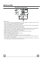
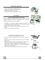
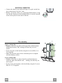
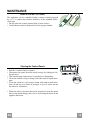
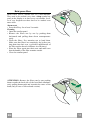
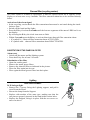
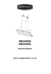
RMG1H60SG
RMG1H90SG
Instructions Manual
www.rangemaster.co.uk
Instructions Manual
INDEX
RECOMMENDATIONS AND SUGGESTIONS ......................................................................................................................3
CHARACTERISTICS..............................................................................................................................................................4
INSTALLATION ......................................................................................................................................................................6
USE.........................................................................................................................................................................................9
MAINTENANCE....................................................................................................................................................................10
EN
2
2
RECOMMENDATIONS AND SUGGESTIONS
The Instructions for Use apply to several versions of this appliance. Accordingly, you may find descriptions of individual features that do not apply to
your specific appliance.
INSTALLATION
• The manufacturer will not be held liable for any damages resulting from incorrect or improper installation.
• The minimum safety distance between the cooker top and the extractor
hood is 450 mm.
• Check that the mains voltage corresponds to that indicated on the rating
plate fixed to the inside of the hood.
• For Class I appliances, check that the domestic power supply guarantees
adequate earthing.
Connect the extractor to the exhaust flue through a pipe of minimum diameter 120 mm. The route of the flue must be as short as possible.
• Do not connect the extractor hood to exhaust ducts carrying combustion
fumes (boilers, fireplaces, etc.).
• If the extractor is used in conjunction with non-electrical appliances (e.g. gas
burning appliances), a sufficient degree of aeration must be guaranteed in
the room in order to prevent the backflow of exhaust gas. The kitchen must
have an opening communicating directly with the open air in order to
guarantee the entry of clean air.
450 mm min.
USE
• The extractor hood has been designed exclusively for domestic use to eliminate kitchen smells.
• Never use the hood for purposes other than for which it has ben designed.
• Never leave high naked flames under the hood when it is in operation.
• Adjust the flame intensity to direct it onto the bottom of the pan only, making
sure that it does not engulf the sides.
• Deep fat fryers must be continuously monitored during use: overheated oil
can burst into flames.
• Do not flambè under the range hood; risk of fire
• This appliance is not intended for use by persons (including children) with
reduced physical, sensory or mental capabilities, or lack of experience and
knowledge, unless they have been given supervision or instruction concerning use of the appliance by a person responsible for their safety.
• Children should be supervised to ensure that they do not play with the appliance.
MAINTENANCE
• Switch off or unplug the appliance from the mains supply before carrying out
any maintenance work.
• Clean and/or replace the Filters after the specified time period.
• Clean the hood using a damp cloth and a neutral liquid detergent.
The symbol
on the product or on its packaging indicates that this product may not be treated
as household waste. Instead it shall be handed over to the applicable collection point for the
recycling of electrical and electronic equipment. By ensuring this product is disposed of correctly,
you will help prevent potential negative consequences for the environment and human health,
which could otherwise be caused by inappropriate waste handling of this product. For more
detailed information about recycling of this product, please contact your local city office, your
household waste disposal service or the shop where you purchased the product.
EN
3
3
CHARACTERISTICS
Dimensions
EN
4
4
Components
Q.ty Product Components
1 Hood Body, complete with: Controls, Light,
Blower, Filters
2
1 Telescopic Chimney comprising:
2.1
1 Upper Section
2.2
1 Lower Section
9
1 Reducer Flange ø 150-120 mm
10
1 Adapting ring ø 120-125 mm
14.1
2 Air Outlet Connection Extension
15
1 Air Outlet Connection
Ref. Q.ty Installation Components
7.2.1 2 Upper Chimney Section Fixing Brackets
7.3
1 Air Outlet Connection Support
11
6 Wall Plugs
12a
6 Screws 4,2 x 44,4
12c
6 Screws 2,9 x 9,5
Q.ty Documentation
1 Instruction Manual
15
Ref.
1
14.1
7.3
10
12a
7.2.1
11
9
2.1
12c
2
2.2
11
12a
1
EN
5
5
INSTALLATION
1÷2
Wall drilling and bracket fixing
11
X
7.2.1
116
116
1040
450 mm min
12a
Wall marking:
• Draw a vertical line on the supporting wall up to the ceiling, or as high as practical, at the
centre of the area in which the hood will be installed.
• Draw a horizontal line at 1040 mm above the hob.
• Place bracket 7.2.1 on the wall as shown about 1-2 mm from the ceiling or upper limit aligning the centre (notch) with the vertical reference line.
• Mark the wall at the centres of the holes in the bracket.
• Place bracket 7.2.1 on the wall as shown at X mm below the first bracket (X = height of the
upper chimney section supplied), aligning the centre (notch) with the vertical line.
• Mark the wall at the centres of the holes in the bracket.
• Mark a reference point as indicated at 116 mm from the vertical reference.
• Repeat this operation on the other side.
• Drill ø 8 mm holes at all the centre points marked.
• Insert the wall plugs 11 in the holes.
• Fix the lower bracket 7.2.1 using the 12a screws (4,2 x 44,4) supplied.
• Fix the upper bracket 7.2.1 and the air outlet connection support 7.3 together using the 2
screws 12a (4,2 x 44,4) supplied.
• Insert the two screws 12a (4,2 x 44,4) supplied in the hood body fixing holes, leaving a gap
of 5-6 mm between the wall and the head of the screw.
EN
6
6
Mounting the hood body
• Before attaching the hood body, tighten the two screws Vr located on the hood body mounting points.
• Hook the hood body onto the screws 12a.
• Fully tighten support screws 12a.
• Adjust screws Vr to level the hood body.
Vr
12a
Connections
DUCTED VERSION AIR EXHAUST SYSTEM
When installing the ducted version, connect the hood to the
chimney using either a flexible or rigid pipe ø 150 or 125 mm,
the choice of which is left to the installer.
ø 150
ø 125
10
9
• To install a ø 125 mm air exhaust connection, insert the reducer flange 9 on the hood body air outlet and the adapting
ring ø120-125 10 on the reducer flange.
• Fix the pipe in position using sufficient pipe clamps (not supplied).
• Remove any activated charcoal filters.
RECIRCULATION VERSION AIR OUTLET
• Insert the connection extension pieces laterally 14.1 in connection 15.
• Insert the Connector 15 into the Support bracket 7.3 and fix it
with a screw.
• Make sure that the outlet of the extension pieces 14.1 is horizontally and vertically aligned with the chimney outlets.
• Connect the air outlet connection 15 to the hood body outlet
using either a flexible or rigid pipe ø 150 mm, the choice of
which is left to the installer.
• Ensure that the activated charcoal filters have been inserted.
EN
7.3
14.1
15
ø 150
7
7
ELECTRICAL CONNECTION
• Connect the hood to the mains through a two-pole switch having a contact gap of at least 3 mm.
• Remove the grease filters (see paragraph Maintenance) being
sure that the connector of the feeding cable is correctly inserted
in the socket placed on the side of the fan.
7.2.1
Flue assembly
Upper exhaust flue
• Slightly widen the two sides of the upper flue and hook them
behind the brackets 7.2.1, making sure that they are well
seated.
• Secure the sides to the brackets using the 4 screws 12c (2,9 x
9,5) supplied.
• Make sure that the outlet of the extensions pieces is aligned
with the chimney outlets.
12c
2.1
2
12c
2.2
12c
Lower exhaust flue
• Slightly widen the two sides of the flue and hook them between the upper flue and the wall, making sure that they are
well seated.
• Fix the lower part laterally to the hood body using the 2 screws
12c (2,9 x 9,5) supplied.
EN
8
8
USE
A
B
C
D
F
E
G
H
I
L
Control board
Key Function
A
Switches the extractor motor on and off at the latest
selected speed
B
Decreases the suction speed.
C
Increases the suction speed.
D
By pressing this key it is possible to start the intensive speed from any previously selected speed except the Delay-function and 24H-function. This
speed has been timed at 10 minutes. After that time
the system activates automatically the latest selected
speed. This function is suitable for cooking conditions when vapours and smells are at the utmost emission.
E
By pressing this key it is possible to set up the motor
to a suction speed at 100 m3/h .
F
G
H
I
L
Display
Indicates the selected speed.
The number of lit LEDS decreases.
The number of lit LEDS increases.
I flashes and the LEDS are all lit.
By pressing the key the function is
stopped.
24 appears and the LEDS extinguish one
by one.
By pressing the key the function is
stopped
By pressing this key it is possible to set the delayed A flashing clock-symbol appears.
shutdown of the motor and the lighting to 30 min- By pressing the key the function is
utes. This function is suitable for a complete elimi- stopped
nation of residual cooking odours. Functioning only
when the motor is on(not during the 24H-function or
intensive function). By pressing the key the function
is stopped
By pressing this key for about 2 seconds it is possi- After 100 working hours a drop-symbol
ble to reset the filter saturation alarm
appears. Metal grease filters have to be
washed.
After 200 working hours C appears.
Charcoal filters have to replaced.
By pressing this key the intensity of the lighting
system can be decreased.
Switches on/off the lighting system at the maximum
intensity.
By pressing this key the intensity of the lighting
system can be increased.
Keyboard lock: it is possible to jam the keyboard when, for example, cleaning the glass. The
motor and lights are switched off.
By pressing the F-key (Delay) for about 5 seconds the keyboard block can be activated or deactivated. This function is confirmed by a Beep and by moving motor LEDS on display.
EN
9
9
MAINTENANCE
REMOTE CONTROL (OPTIONAL)
The appliance can be controlled using a remote control powered
by a 1.5 V carbon-zinc alkaline batteries of the standard LR03AAA type.
• Do not place the remote control near to heat sources.
• Used batteries must be disposed of in the proper manner.
Cleaning the Comfort Panels
• Pull the Comfort Panel to open it.
• Disconnect the panel from the hood canopy by sliding the fixing pin lever.
• The comfort panel must never be washed in a dishwasher.
• Clean the outside using a damp cloth and neutral liquid detergent.
• Clean the inside as well using a damp cloth and neutral detergent; do not use wet cloths or sponges, or jets of water; do not
use abrasive substances.
• When the above operation has been completed, hook the panel
back to the hood canopy and close it by turning the knob in the
opposite direction.
EN
1
10
0
Metal grease filters
Metal filters can be washed also in a dish machine.
They need to be washed every time a drop-symbol appears in the display or at least every two months. In case of very frequent use these have to be washed even
more often.
Alarm reset
• Press the G-key for at least 2 seconds.
Cleaning
• Open the comfort panel.
• Remove the filters one by one by pushing them
backwards and pulling them down contemporaneously.
• Wash the filters. Pay attention not to bend them.
Make sure that filters are completely dry before putting them into their seat. (a possible modification of
the filter surface doesn’t influence its efficiency).
• Place the filters again into their seats and make sure
that the handle of the filter remains outside.
• Close the comfort panel.
ATTENTION: Remove the filters one by one pushing
them towards the back side of the hood and simultaneously pulling downwards and towards the centre of the
hood (only in case of 60 cm hood version).
EN
1
11
1
Charcoal filter (recycling version)
This filter cannot be washed or regenerated. It must be replaced when the C appears on the
display or at least once every 4 months. The filter saturation alarm has to be activated already
before.
Activation of the alarm signal
• In the recycling version hoods the filter saturation alarm must be activated during the installation or later.
• Switch off the hood and the lights.
• Press the E-key for about 5 seconds until the last two segments of the motor LEDS are lit on
the display.
• By releasing the E-key the clock icon starts to flash.
• Within 3 seconds press the D-key to activate/deactivate charcoal filter saturation alarm.
• C-symbol lit - charcoal filter saturation alarm ACTIVATED.
• C-symbol unlit - charcoal filter saturation alarm DEACTIVATED.
SUBSTITUTION OF THE CHARCOAL FILTER
Alarm reset
• Switch off the motor and the lighting system.
• Press the G-key for at least 2 seconds.
Substitution of the filter
• Open the confort panel.
• Remove the metal grease filters.
• Remove the charcoal filter as indicated in the picture.
• Place the filter again into its seat.
• Place again the metal grease filters into their place.
Lighting
LIGHT REPLACEMENT
20 W halogen light.
• Remove the 2 screws fixing the Lighting support, and pull it
out of from the Hood.
• Extract the lamp from the Support.
• Replace with another of the same type, making sure that the
two pins are properly inserted in the lamp holder socket holes.
• Replace the Support, fixing it in place with the two screws removed as above.
EN
1
12
2
AGA RANGEMASTER LTD.
436004190_ver1