1
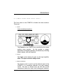
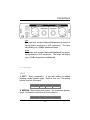
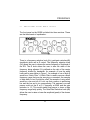
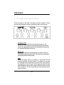
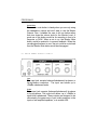
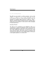
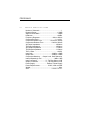
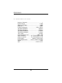
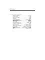
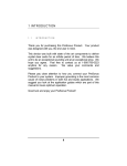
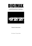
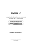
COMP16
S M A R T
C O M P R E S S O R
HP4
H E A D P H O N E
D I S T R I B U T I O N
A M P L I F I E R
EQ3B
3 BAND PARAMETRIC EQALIZER
USERS MANUAL
Version 2.0
PreSonus Audio Electronics
COMP16
S M A R T
C O M P R E S S O R
HP4
H E A D P H O N E
D I S T R I B U T I O N
A M P L I F I E R
EQ3B
3 BAND PARAMETRIC EQALIZER
USERS MANUAL
Version 1.0
© 2003, PreSonus Audio Electronics, Incorporated.
All rights reserved.
W A R R A N T Y
PreSonus Limited Warranty
PreSonus Audio Electronics Inc. warrants this product to be free of defects in material and
workmanship for a period of one year from the date of original retail purchase. This warranty is
enforceable only by the original retail purchaser. To be protected by this warranty, the
purchaser must complete and return the enclosed warranty card within 14 days of purchase.
During the warranty period PreSonus shall, at its sole and absolute option, either repair or
replace, free of charge, any product that proves to be defective on inspection by PreSonus or its
authorized service representative. To obtain warranty service, the purchaser must first call or
write PreSonus at the address and telephone number printed below to obtain a Return
Authorization Number and instructions of where to return the unit for service. All inquiries must
be accompanied by a description of the problem. All authorized returns must be sent to the
PreSonus repair facility postage prepaid, insured and properly packaged. PreSonus reserves
the right to update any unit returned for repair. PreSonus reserves the right to change or
improve the design of the product at any time without prior notice. This warranty does not cover
claims for damage due to abuse, neglect, alteration or attempted repair by unauthorized
personnel, and is limited to failures arising during normal use that are due to defects in material
or workmanship in the product. Any implied warranties, including implied warranties of
merchantability and fitness for a particular purpose, are limited in duration to the length of this
limited warranty. Some states do not allow limitations on how long an implied warranty lasts, so
the above limitation may not apply to you. In no event will PreSonus be liable for incidental,
consequential or other damages resulting from the breach of any express or implied warranty,
including , among other things, damage to property, damage based on inconvenience or on loss
of use of the product, and, to the extent permitted by law, damages for personal injury. Some
states do not allow the exclusion of limitation of incidental or consequential damages, so the
above limitation or exclusion may not apply to you. This warranty gives you specific legal rights,
and you may also have other rights which vary form state to state. This warranty only applies to
products sold and used in the United States of America. For warranty information in all other
countries please refer to your local distributor.
PreSonus Audio Electronics, Inc.
7257 Florida Blvd.
Baton Rouge, LA 70806
(225) 216-7887
© 2003, PreSonus Audio Electronics, Incorporated. All rights reserved.
TABLE OF CONTENTS
1
Overview
1.1 Introduction
2
4
Comp16
2.1 A Word About Compression
5
2.2 Front/Back Panel Basic Layout
7
2.3 Presets
9
2.4 Application Guide
14
3
EQ3B
3.1 Front/Back Panel Basic Layout
17
3.2 Application Guide
19
4
HP4
4.1 Front/Back Panel Basic Layout
21
4.2 Application Guide
23
5
Technical Specifications
5.1 COMP16 Specifications
24
5.2 EQ3B Specifications
25
5.3 HP4 Specifications
26
3
1 INTRODUCTION
1 . 1
INTRODUCTION
Thank you for purchasing this PreSonus Product. Your product
was designed with you, the end user in mind.
This device was built with state of the art components to deliver
crystal clear audio for an infinite period of time. We believe this
unit to be an exceptional sounding unit at an exceptional price. We
hope you agree. Feel free to contact us at 1-800-750-0323
anytime for any reason.
We value your comments and
suggestions.
Please pay close attention to how you connect your PreSonus
Product to your system. Improper grounding is the most common
cause of noise problems in both live and studio applications. We
suggest you look at the application guides which are part of this
manual to insure optimum operation.
Good luck and enjoy your PreSonus Product!
4
PRESONUS
2 . 1
A
W ORD
ABOUT
COMPRESSI ON
Punch, apparent loudness, presence… just three of many terms
used to describe the effects of compression/ limiting.
Compression and limiting are forms of dynamic range (volume)
control. Audio signals have very wide peak to average signal level
ratios (sometimes referred to as dynamic range which is the
difference between the loudest level and the softest level). The
peak signal can cause overload in the audio recording or
reproduction
chain
resulting
in
signal
distortion.
A
compressor/limiter is a type of amplifier in which gain is dependent
on the signal level passing through it. You can set the maximum
level a compressor/limiter allows to pass through, thereby causing
automatic gain reduction above some predetermined signal level or
threshold.
Compression refers basically to the ability to reduce the output
level of an audio signal by a fixed ratio relative to the input. It is
useful for lowering the dynamic range of an instrument or vocal,
making it easier to record without distorting the recorder. It also
assists in the mixing process by reducing the amount of level
changes needed for a particular instrument. Take, for example, a
vocalist who moves around in front of the microphone while
performing, thus making the output level vary up and down
unnaturally. A compressor can be applied to the signal to help
correct this recording problem by reducing the ‘louder’ passages
enough to be compatible with the overall performance.
How severely the compressor reduces the signal is determined by
the compression ratio and compression threshold. A ratio of 2:1 or
less is considered mild compression, reducing the output by two for
signals greater than the compression threshold. Ratios above 10:1
5
PRESONUS
are considered hard limiting. Limiting refers to the point at which
the signal is restrained from going any louder at the output.
The level of input signal at which the output is reduced is
determined by the compression threshold. As the compression
threshold is lowered, more and more of the input signal is
compressed (assuming a nominal input signal level). Care must
be taken not to ‘over compress’ a signal. Too much compression
destroys the acoustical dynamic response of a performance.
(‘Over compression’, however, is used by some engineers as an
effect, and with killer results!)
Compressor/limiters are commonly used for many audio
applications. A kick drum can get lost in a wall of electric guitars.
No matter how much level is increased, the kick drum stays ‘lost in
the mud’. Add a touch of compression and tighten up that kick
drum sound allowing it to ‘punch’ through without having to crank
the level way up.
A vocal performance usually has a wide dynamic range. Transients
(the very loudest portion of the signal) can be far outside the
average level of the vocal signal. It is extremely difficult to ride the
level with a console fader. A compressor/limiter automatically
controls gain without altering the subtleties of the performance.
A solo guitar can seem to be masked by the rhythm guitars.
Compression can make your ‘lead’ soar above the track without
shoving the fader through the roof .
Bass guitar can be difficult to record . A consistent level with good
attack can be achieved with proper compression . Your bass
doesn’t have to be washed out in the low end of the mix . Let the
compressor/limiter give your bass the punch it needs to drive the
bottom of the track .
PRESONUS
2 . 2
COMP1 6
FRONT
PANEL
BASI C
L AYOUT
The front panel on the COMP16 is divided into three sections.
These are:
1. Presets:
Sixteen selectable preset positions.
The Presets for the COMP16 are controlled by this sixteen
position rotary encoder.
As the encoder is rotated,
parameters are digitally switched, simultaneously controlling
attack, release, ratio and threshold.
2. Controls:
The Input control adjusts the gain on the input amplifier.
Note: The input control is always active.
3. Output & Pushbuttons
The Output control is used to set the desired output of the
COMP16. It is sometimes referred to as ‘gain makeup’
control. This term is derived from the fact that as the
compressor lowers the output level during gain reduction,
7
PRESONUS
the overall signal level is lowered, requiring the user to
‘makeup’ the gain thereby restoring the original signal level.
Output to Meter
This button selects the function of the Output/Gain
Reduction meter. Pushed out, the meter gives you the level
of the gain reduction. Pushed in, the meter gives you the
level of the signal after compression; the output level.
Bypass
If the BYPASS button is not pushed in, the COMP16 is
processing the signal (compressing). When pushed in, the
COMP16 is no longer compressing the signal, however the
input gain setting remains active.
2 . 2
COMP1 6
BACK
PANEL
L AYOUT
PRESONUS
Input
The input jack accepts balanced/unbalanced tip-sleeve or
tip-ring-sleeve connectors or XLR connectors. The input
can handle up to +22dBu unbalanced levels.
Output
The output jack accepts (balanced/unbalanced) tip-sleeve,
tip-ring-sleeve or XLR connectors. The output will deliver
up to +22dBu in signal level unbalanced.
2 . 3
PRESETS
Vocal
1 SOFT - Easy compression. A low ratio setting for ballads
allowing a wider dynamic range. Good for ‘live’ use. This setting
lets the vocal sit ‘in the track’.
Threshold
-8.2dB
Ratio
1.8:1
Attack
0.002mS
Release
38mS
2 MEDIUM - More limiting than preset 1 for a narrower dynamic
range. It moves the vocal more up front in the mix.
Threshold
Ratio
Attack
9
Release
PRESONUS
-3.3dB
2.8:1
0.002mS
38mS
3 SCREAMER - For loud vocals. Fairly hard compression for a
vocalist who is ‘on’ and ‘off’ the microphone a lot. It puts the voice
‘in your face’.
Threshold
-1.1dB
Ratio
3.8:1
Attack
0.002mS
Release
38mS
Perc.
1 SNARE/KICK - Allows the first transient through and
compresses the rest of the signal giving a hard snap up front with a
longer release.
Threshold
-2.1dB
Ratio
3.5:1
Attack
78mS
Release
300mS
2 L/R (Mono) OVERHEAD - A low ratio and threshold gives a ‘fat’
contour to even out the sound from overhead drum mics. Low end
is increased and the overall sound is more present and less
ambient. More ‘boom’ less ‘room’.
Threshold
-13.7dB
Ratio
1.3:1
Attack
27mS
Release
128mS
Fretted
1 ELECTRIC BASS - A fast attack and slow release to tighten up
the electric bass and give you control for more consistent level.
PRESONUS
Threshold
-4.4dB
Ratio
2.6:1
Attack
45.7mS
Release
189mS
2 ACOUSTIC GUITAR - This setting accentuates the attack of
the acoustic guitar and helps maintain an even signal level keeping
the acoustic guitar from disappearing in the track.
Threshold
-6.3dB
Ratio
3.4:1
Attack
188mS
Release
400mS
3 ELECTRIC GUITAR - A setting for ‘crunch’ electric rhythm
guitar. A slow attack helps get the electric rhythm guitar up close
and personal and gives punch to your crunch.
Threshold
0.1dB
Ratio
2.4:1
Attack
26mS
Release
194mS
Keyboards
1 PIANO - A special setting for an even level. Designed to help
even up the top and bottom of an acoustic piano. Helps the left
hand be heard with the right hand.
Threshold
-10.8dB
Ratio
1.9:1
Attack
108mS
Release
112mS
2 SYNTH - Fast attack and release for synthesizer horn stabs and
for bass lines played on a synthesizer.
Threshold
-11.9dB
Ratio
1.8:1
Attack
0.002mS
11
Release
85mS
PRESONUS
3 ORCHESTRAL - Use this setting for string ‘pads’ and other
types of synthesized orchestra parts. It will decrease the overall
dynamic range for easier placement in the mix.
Threshold
3.3dB
Ratio
2.5:1
Attack
1.8mS
Release
50mS
Limit
1 MONO LIMITER - Just as the name implies. A hard limiter
setting (brick wall) ideal for controlling level to the 2 track mixdown
deck or Mono output.
Threshold
5.5dB
Ratio
7.1:1
Attack
0.001mS
Release
98mS
2 CONTOUR - A contoured setting for use on the Mono output to
fatten up the mix.
Threshold
-13.4dB
Ratio
1.2:1
Attack
0.002mS
Release
182mS
Effects
1 SQUEEZE - Dynamic compression for solo work, especially
electric guitar. It gives you that glassy ‘tele/strat’ sound. A true
classic.
Threshold
-4.6dB
Ratio
2.4:1
Attack
7.2mS
Release
93mS
PRESONUS
2 PUMP - Make the COMP16 ‘pump up the prime’. A setting for
making the compressor pump in a desirable way. This effect is
good for snare drum to increase the length of the transient by
bringing the signal up after the initial spike. Very contemporary.
Threshold
0dB
Ratio
1.9:1
Attack
1mS
Release
0.001mS
3 Tamer – Tame that funky low end. Designed to help control low
end transients. This setting is especially useful for Bass Guitar.
Threshold
-8dB
Ratio
2:1
Attack
1mS
13
Release
50mS
PRESONUS
2 . 4
APPL I CATI ON
QUI CK
GUI DE
START
1. Connect your COMP16 using one input jack (TS, TRS, or
XLR) and one or more of the output jacks(TS, TRS, or
XLR).
2. Select your preset. (Refer to the preset descriptions above.
Remember that the Ratio, Attack and Release knobs are
only active in Manual mode.)
3. Do not push the bypass button in.
4. Turn the Input knob all the way to -20 (counter-clockwise).
5. Set the Output knob on 0.
6. Slowly turn the Input knob up (clockwise) until the Gain
Reduction meters begin to move. Continue to rotate the
Input knob until the Gain Reduction meters read between -5
and -7.
7. Adjust the Output knob to the desired output level.
You should now have a very natural sounding compressed
signal. Of course you should experiment with the settings to
suit your taste.
14
PRESONUS
BASI C
CONNECTI ONS
The COMP16 can be hooked to another processor, such as the
EQ3B or TubePre in a live or studio environment. Please note that
a microphone can not be plugged directly into the COMP16. The
microphone has to be preamplified first. The TubePre would be a
perfect preamp in front of the COMP16. We do recommend that
whenever possible, balanced cables be used. Examples of
balanced cables would be XLR or TRS (Tip – Ring – Sleeve). A
balanced cable is preferred because it generally has a greater level
of noise rejection. In other words it is less susceptible to outside
interference.
Use with a Console/Mixer Insert
The COMP16 can be connected to an insert point on a console
(mixer) by using a TRS Y-cable. This cable is Y-shaped, has a
single TRS ¼” jack on one end and two ¼” TS (Tips-Sleeve) jacks
on the other end. The single end will look like a stereo ¼”
connector jack. This end of the cable plugs into the insert jack on
the mixer channel. The other ends of the cable plug into the input
and output of the EQ3B. If the EQ3B does not work immediately,
you may want to try changing the jacks that are plugged into the
input and output of the unit.
15
PRESONUS
BASIC
OPERATING
PROCEDURES
Setting Compression Amount
Your COMP16 was designed with a fixed threshold mode of
operation. This differs from other compressors in the fact that
there is no threshold control. This offers the unique ability to
immediately hear the sometimes subtle differences between
presets which each have unique threshold settings. In setting the
compression amount, always begin with the Input control all the
way counter-clockwise (-20dB), and slowly increase the input until
the Gain Reduction meters begin to register the compression
activity. The more you crank up the Input the more compression
your signal will experience. Always pay close attention to the best
judge of your sound, your ear. You should also frequently remove
the compression from the signal using the Bypass button to listen
to the changes in your sound. In modern recording practice, it is
customary to adjust the Output control such that the Input and
Output level are of equal amounts according to the Output/Gain
Reduction meter. This gives you an equal level output so that you
can switch processing in and out to compare difference.
PRESONUS
3 . 1
EQ3 B
FRONT
PANEL
BASI C
L AYOUT
The front panel on the EQ3B is divided into three sections. These
are the three bands of equalization:
There is a frequency selection knob (Hz), gain/gain reduction(dB)
(amplitude) knob and a Q control. The frequency selection knob
(Hz) allows the user to choose the center frequency of that band of
the EQ. The Q knob allows the user to alter the width of the
frequency being adjusted. Q is defined as the ratio of the center
frequency divided by bandwidth. An example of how the width
looks can be seen below in Figure 1. An example of use of high Q
would be a “Notch Filter”. A Notch Filter is used to remove a small
frequency range that may be annoying or unwanted. An example
of wide width or low Q would be a bell. An example of using a bell
would be a low end roll off. Let’s say that a person is performing
live and the low end is too overpowering. The engineer or sound
person could set the Q at 0.1, frequency at 80Hz and the gain
reduction to -12. This would enable that person to lower a wide
frequency range fairly quickly. The Gain/Gain Reduction knob (dB)
allows the user to raise or lower the amplitude (peak) of the chosen
frequency.
17
PRESONUS
Figure1
Bypass
If the BYPASS button is not pushed in, the EQ3B is
processing the signal (equalizing). Pushed in, the EQ3B is
no longer equalizing the signal.
80Hz
The 80Hz button is a low end roll off filter. When pushed in,
the 80Hz button causes all frequencies below 80Hz to be
attenuated (dropped) by 12dB. This filter can be handy in
several live and studio applications. One instance would be
for use on a vocal. The 80Hz filter would help reduce the
“boominess” of a deep vocal.
PRESONUS
3 . 1
BACK
PANEL
BASI C
L AYOUT
Input
The input jack accepts balanced/unbalanced tip-sleeve or
tip-ring-sleeve connectors or XLR connectors. The input
can handle up to +24dBu unbalanced levels.
Output
The output jack accepts (balanced/unbalanced) tip-sleeve,
tip-ring-sleeve or XLR connectors. The output will deliver
up to +24dBu in signal level unbalanced.
3 . 2
APPL I CATI ON
GUI DE
The EQ3B can be hooked to another processor, such as the
COMP16 or TubePre in a live or studio environment. We do
recommend that whenever possible, balanced cables be used.
Examples of balanced cables would be XLR or TRS (Tip – Ring –
Sleeve). A balanced cable is preferred because it generally has a
greater level of noise rejection. In other words it is less susceptible
to outside interference.
Use with a Console/Mixer Insert
19
PRESONUS
The EQ3B can be connected to an insert point on a console
(mixer) by using a TRS Y-cable. This cable is Y-shaped, has a
single TRS ¼” jack on one end and two ¼” TS (Tips-Sleeve) jacks
on the other end. The single end will look like a stereo ¼”
connector jack. This end of the cable plugs into the insert jack on
the mixer channel. The other ends of the cable plug into the input
and output of the EQ3B. If the EQ3B does not work immediately,
you may want to try changing the jacks that are plugged into the
input and output of the unit.
PRESONUS
4 . 1
HP4
FRONT
PANEL
BASI C
L AYOUT
The front panel on the HP4 is divided into three sections. These
are the potentiometers (knobs), headphone jacks, and buttons:
Headphone Volume
The HP4 has the potential to be very loud (it goes to 12).
Please be careful when you first start passing sound through
the unit. It is generally a good idea to start with the volume set
at 1 and then bring the volume up.
Monitor Level
The monitor level knob corresponds to the output volume of
the output on the back of the HP4. The level can be muted by
pressing the Monitor Mute button.
Mono
When the Mono button is pushed in, each input will be
summed together on each output. For example, if you plug
a CD player into the left input and press the mono button,
the signal from the left input will be present in the left and
right headphone and master output. When the Mono button
is not pushed in, the left output will have the left input signal
and vice-versa.
21
PRESONUS
Monitor Mute
The monitor mute button is handy when you are only using
the headphone outputs and don’t want to use the Master
Outputs. Also, it enables the user to hit one button rather
than turn down the volume knob for the Monitor Level. A
good use of this button would be for recording in front of a
computer or DAW. When a mic is on, the Monitor Mute
button would be pushed in to prevent feedback. When the
recording/performance is over, the mic could be muted and
then the Monitor Mute button would be disengaged.
4 . 1
BACK
PANEL
BASI C
L AYOUT
Input
The input jack accepts balanced/unbalanced tip-sleeve or
tip-ring-sleeve connectors. The input can handle up to
+24dBu unbalanced levels.
Output
The output jack accepts (balanced/unbalanced) tip-sleeve
or tip-ring-sleeve. The output will deliver up to +24dBu in
signal level unbalanced. These outputs are designed to be
connected to the power amp of your studio speakers, to the
inputs of self amplified speakers, or to another HP4.
PRESONUS
4 . 2
APPL I CATI ON
GUI DE
The HP4 can be hooked to another processor, such as the
COMP16 or TubePre in a live or studio environment. We do
recommend that whenever possible, balanced cables be used. An
example of a balanced cable would be a TRS (Tip – Ring –
Sleeve). A balanced cable is preferred because it generally has a
greater level of noise rejection. In other words it is less susceptible
to outside interference.
Use with a Console
The HP4 can be connected to the headphone output of a
console/mixer to multiply the headphone outputs. Care should be
taken that the headphone output level of the console/mixer is not
set to high. Setting the output level to the HP4 too loud, could
cause the unit to distort. The monitor outputs are designed to be
connected to the power amp of your studio speakers, to the inputs
of self amplified speakers, or to another HP4.
23
PRESONUS
5 . 1
COMP1 6
SPECI FI CATI ONS
Number of Channels ...................................................... 1
Dynamic Range .................................................. >115dB
Signal to Noise Ratio ............................................ >95dB
Headroom ........................................................... +22dBu
Frequency Response .............................. 10Hz to 50kHz
Compression Ratio ......................................... 1:1 to 20:1
Compressor Attack Time .................... 0.01mS to 100mS
Compressor Release Time .................... 10mS to 500mS
XLR Input Impedance ...................................... 10kOhms
TRS Input Impedance ...................................... 10kOhms
XLR Output Impedance ..................................... 51Ohms
TRS Output Impedance ..................................... 51Ohms
THD + Noise ....................................................... <0.05%
Input Gain ...............................................-20dB to +20dB
Output Gain ............................................-20dB to +20dB
Compressor Metering ..... Output Level, Gain Reduction
Internal Operating Level ............................... 0dBu = 0dB
Input Connectors .................... ¼”, Tip Ring Sleeve, XLR
Output Connectors ................. ¼”, Tip Ring Sleeve, XLR
Power Supply............................. External, Linear Supply
Power Requirements ................... 16VAC,1000 mA 20W
Weight ...................................................................... 4lbs.
Size ........................................................ 5.5”X5.5”X1.75”
PRESONUS
5 . 2
EQ3 B
SPECI FI CATI ONS
Number of Channels ...................................................... 1
Dynamic Range .................................................. >115dB
Signal to Noise Ratio ............................................ >95dB
Headroom ........................................................... +22dBu
Frequency Response .............................. 10Hz to 50kHz
XLR Input Impedance ...................................... 10kOhms
TRS Input Impedance ...................................... 10kOhms
XLR Output Impedance .................................... 51 Ohms
TRS Output Impedance .................................... 51 Ohms
THD + Noise ..................................................... <0.002%
Internal Operating Level ............................. +0dBu = 0dB
Input Connectors .................. 1/4”, Tip Ring Sleeve, XLR
Output Connectors ............... 1/4”, Tip Ring Sleeve, XLR
Power Supply............................. External, Linear Supply
Power Requirements ............16VAC, 1000mA, 20 Watts
Weight ..................................................................... 4 lbs.
Size ........................................................ 5.5”X5.5”X1.75”
25
PRESONUS
5 . 3
HP4
SPECI FI CATI ONS
Number of Channels ......................................... 1 in 5 out
Dynamic Range .................................................. >115dB
Signal to Noise Ratio ............................................ >95dB
Headroom ........................................................... +22dBu
Frequency Response .............................. 10Hz to 50kHz
Input Impedance .............................................. 10kOhms
Master Output Impedance ................................ 51 Ohms
THD + Noise ..................................................... <0.002%
Internal Operating Level ............................. +0dBu = 0dB
Headphone Output Power .................................. 150mW
Input Connectors ........................... 1/4”, Tip Ring Sleeve
Master Output Connectors ............ 1/4”, Tip Ring Sleeve
Power Supply............................. External, Linear Supply
Power Requirements ............16VAC, 1000mA, 20 Watts
Weight ..................................................................... 4 lbs.
Size ........................................................ 5.5”X5.5”X1.75”