1
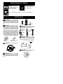
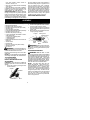
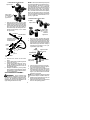
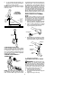
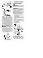
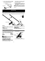
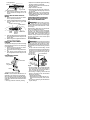
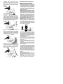
ENGLISH
R
Instruction Manual
Manual de Instrucciones
Manuel d’Instructions
PPB4000C
ESPAÑOL
NOT DESIGNED FOR USE WITH
ELECTRIC POWERHEADS
NO ESTA DISEÑADO PARA EL USO CON
CABEZAS DE MOTOR ELÉCTRICO
NON CONÇU POUR L’USAGE AVEC
BLOC ---MOTEURS ÉLECTRIQUES
Electrolux Home Products, Inc.
250 Bobby Jones Expressway
Augusta, GA 30907
Copyright E2003 Electrolux Home Products, Inc.
530164694
12/8/03
FRANÇAIS
DANGER:
Read and follow all Safety Rules and Operating Instructions before
using this product. Failure to do so can result in serious injury.
PELIGRO:
Lea el manual de instrucciones y siga todas las advertencias e
instrucciones de seguridad. El no hacerlo puede resultar en lesiones graves.
DANGER:
Lire le manuel d’instructions et bien respecter tous les avertissements et toutes les instructions de sécurité. Tout défaut de le
faire pourrait entraîner des blessures graves.
IDENTIFICATION OF SYMBOLS
DANGER!
Read and understand the
instruction manual before
using the brushcutter.
This brushcutter
can be dangerous! Careless or
improper use can cause
serious or even fatal injury.
Always wear appropriateear protection, eye protection and head protection.
SAFETY RULES
WARNING: When using gardening
appliances, basic safety precautions should
always be followed to reduce the risk of fire
and serious injury. Read and follow all instructions. Failure to do so can result in serious injury.
DANGER: This power tool can be dangerous! This unit can cause serious injury including amputation or blindness to the operator and others. The warnings and safety
instructions in this manual must be followed to
provide reasonable safety and efficiency in
using the unit. The operator is responsible for
following the warnings and instructions in this
manual and on the unit. Read the entire instruction manual before assembling and using
the unit! Restrict the use of this unit to persons
who read, understand, and follow the warnings and instructions in this manual and on the
unit. Never allow children to operate this unit.
WARNING: Blade/trimmer line can
throw objects violently. You can be blinded or
injured. Wear eye and leg protection.
ALWAYS WEAR:
Eye
Protection
Leg
Guards
Thrown
objects
Boots
WARNING: Hazard zone for thrown
objects. Blade/trimmer line can throw objects violently. Others can be blinded or injured. Keep
people and animals 50 feet (15 meters) away.
INSTRUCTION
MANUAL
DANGER:
SAFETY INFORMATION
ON THE UNIT
Hazard Zone
Never use flailing devices.
50 Feet
(15 Meters)
WARNING: Do not use trimmer head
as a fastening device for the blade.
DANGER: Blade can thrust violently
away from material it does not cut. Blade
thrust can cause amputation of arms or legs.
Keep people and animals 50 feet (15 meters)
away.
2
S Use only specified blade; make sure it is
properly installed and securely fastened.
S Never start engine with clutch shroud removed. The clutch can fly off and cause serious injury.
S Be sure blade stops turning when engine
idles.
S Make carburetor adjustments with the lower
end supported to prevent the blade from
contacting any object. Hold the unit by hand;
do not use the shoulder strap for support.
S Keep others away when making carburetor
adjustments.
S Use only recommended Poulan PRO! accessories and replacement parts.
S Have all maintenance and service not explained in this manual performed by an authorized service dealer.
WARNING:
The blade continues to
spin after throttle is released or engine is
turned off. The coasting blade can throw objects or seriously cut you if accidentally
touched. Stop the blade by contacting the left
hand side of coasting blade with material already cut.
Stop coasting
blade by contact
with cut material.
FUEL SAFETY
S
S
S
S
OPERATOR SAFETY
S Dress properly. Always wear safety glasses
or similar eye protection when operating, or
performing maintenance on your unit (safety glasses are available). Eye protection
should be marked Z87.
S Always wear face or dust mask if operation
is dusty.
S Always wear heavy, long pants, long
sleeves, boots, and gloves. Wearing safety
leg guards is recommended.
S Always wear foot protection. Do not go
barefoot or wear sandals. Stay clear of spinning line/blade.
S Secure hair above shoulder length. Secure or
remove loose clothing and jewelry or clothing
with loosely hanging ties, straps, tassels, etc.
They can be caught in moving parts.
S Being fully covered also helps protect you
from debris and pieces of toxic plants
thrown by spinning line/blade.
S Stay alert. Do not operate unit when you are
tired, ill, upset or under influence of alcohol,
drugs, or medication. Watch what you are
doing; use common sense.
S Wear hearing protection.
S Never start or run the engine inside a closed
room or building. Breathing exhaust fumes
can kill.
S Keep handles free of oil and fuel.
S Always use the handlebar and a properly
adjusted shoulder strap when using brushcutter attachment (see ASSEMBLY).
S
S
S
S
Mix and pour fuel outdoors.
Keep away from sparks or flames.
Use a container approved for fuel.
Do not smoke or allow smoking near fuel or
the unit or while using the unit.
Avoid spilling fuel or oil. Wipe up all fuel
spills before starting engine.
Move at least 10 feet (3 meters) away from fueling site before starting engine.
Stop engine and allow it to cool before removing fuel cap.
Remove fuel cap slowly.
CUTTING SAFETY
WARNING: Inspect the area to be cut
before each use. Remove objects (rocks, broken glass, nails, wire, string, etc.) which can
be thrown or become entangled in the blade or
trimmer line.
S Keep others including children, animals, bystanders, and helpers at least 50 feet (15
meters) away. Stop the engine immediately
if you are approached.
S Always keep engine on the right--hand side
of your body.
S Hold the unit firmly with both hands.
S Keep firm footing and balance. Do not overreach.
S Keep blade/trimmer head below waist level.
S Do not raise powerhead engine above your
waist.
S Keep all parts of your body away from spinning line/blade and muffler.
S Cut from your left to your right. Cutting on
the right side of the shield will throw debris
away from the operator.
S Use only in daylight or good artificial light.
S Use only for jobs explained in this manual.
UNIT/MAINTENANCE SAFETY
WARNING: Disconnect powerhead
spark plug (or disconnect powerhead from power source) before performing maintenance.
S Look for and replace damaged or loose
parts before each use. Look for and repair
fuel leaks before use. Keep unit in good
working condition.
S Throw away blades that are bent, warped,
cracked, broken, or damaged in any other
way. Replace trimmer head parts that are
cracked, chipped, broken, or damaged in
any other way before using the unit.
S Maintain the unit according to recommended
procedures. Keep the blade sharp. Never use
flailing devices, wire, rope, string, etc.
TRANSPORTING AND STORAGE
S Stop the powerhead engine before carrying
unit.
S Keep muffler away from your body.
S Allow engine to cool and secure unit before
storing or transporting it in a vehicle.
S Empty the fuel tank before storing or transporting the unit. Use up fuel left in the carburetor by starting the engine and letting it run
until it stops.
S Store unit and fuel in an area where fuel vapors cannot reach sparks or open flames
3
from water heaters, electric motors or
switches, furnaces, etc.
S Store unit so the blade cannot accidentally
cause injury.
S Store unit indoors, out of reach of children.
If situations occur which are not covered in this
manual, use care and good judgment. If you
need assistance, call 1--800--554--6723.
SPECIAL NOTICE: Exposure to vibrations
through prolonged use of gasoline powered
hand tools could cause blood vessel or nerve
damage in the fingers, hands, and joints of
people prone to circulation disorders or abnormal swellings. Prolonged use in cold weather
has been linked to blood vessel damage in
otherwise healthy people. If symptoms occur
such as numbness, pain, loss of strength,
change in skin color or texture, or loss of feeling in the fingers, hands, or joints, discontinue
the use of this tool and seek medical attention.
An anti-vibration system does not guarantee
the avoidance of these problems. Users who
operatepower tools on a continual and regular
basis must monitor closely their physical
condition and the condition of this tool.
SAVE THESE INSTRUCTIONS
ASSEMBLY
2.
CARTON CONTENTS
Check carton contents for the following:
S Brushcutter attachment
S Handlebar (with clamp and knob)
S Handlebar clamp base (with spacer tabs)
S Shoulder strap
S Upper shoulder strap clamp
S Lower shoulder strap clamp (with spacer tabs)
S Handlebar clamp screws (4)
S Shoulder strap clamp screws (2)
S 4--point weed blade (assembled on brushcutter attachment)
S Large nut for installing blade
S Retaining washer
S Cupped washer
S Metal shield (assembled on brushcutter attachment)
S Trimmer head
S Plastic shield
S Wing nut (screwed onto plastic shield)
S Attachment hanger
S Hex wrench
3.
4.
5.
Coupler
Upper
Shaft
Primary Hole
Guide Recess
Locking/
Lower
Release Attachment
Button
WARNING: Make sure the locking/release button is locked in the primary hole and
the knob is securely tightened before operating the unit.
WARNING: If received assembled, repeat all steps to ensure your unit is properly assembled and all fasteners are secure.
Examine parts for damage. Do not use damaged parts.
NOTE: If you need assistance or find that parts
are missing or damaged, call 1-800-554-6723.
HANDLEBAR ASSEMBLY
DANGER: RISK OF CUT. To avoid
serious injury, the barrier portion of the handlebar
must be installed as shown on the upper shaft of
the powerhead to provide a barrier between operator and the spinning blade. Attach shaft
clamp above arrow on safety warning decal on
the upper shaft (powerhead end of unit). Ensure
handlebar is positioned on handlebar clamp between the arrows on the handlebar decal.
NOTE: The shaft clamp base has four
spacer tabs attached. These tabs are provided to adapt this attachment for use with
powerheads that have a 1" diameter upper
shaft (the shaft clamp will not tighten down securely on the 1" diameter upper shaft without
using these spacer tabs). The tabs must be
broken off completely before use and placed
over the screw holes on the clamp base.
These tabs are not needed for powerheads
with a 7/8" upper shaft.
TOOLS REQUIRED
S Hex wrench (provided)
INSTALLING BRUSHCUTTER
ATTACHMENT
CAUTION: When removing or installing attachments, place the unit on a flat surface for
stability.
1. Loosen the coupler by turning the knob
counterclockwise.
Coupler
LOOSEN
TIGHTEN
Remove the shaft cap from the brushcutter attachment (if present).
Position locking/release button of attachment into guide recess of coupler.
Push the attachment into the coupler until
the locking/release button snaps into the
primary hole.
Before using the unit, tighten the knob securely by turning clockwise.
Knob
4
HANDLEBAR CLAMP BASE
NOTE: The lower shoulder strap clamp has
two spacer tabs attached. These tabs are provided to adapt this attachment for use with
powerheads that have a 1" (2.5 cm)diameter
upper shaft (the shoulder strap clamp will not
tighten down securely on the 1" (2.5 cm) diameter upper shaft without using these spacer
tabs). The tabs must be broken off completely
before use and placed over the screw holes
on the lower shoulder strap clamp. These tabs
are not needed for powerheads with a 7/8"
(2.2 cm) upper shaft.
Spacer Tabs
Spacer Tabs
positioned for use
on 1" diameter
upper shaft
1.
2.
LOWER SHOULDER STRAP
CLAMP
Place the shaft clamp over the upper
shaft above the arrow on the safety decal.
Position the clamp base under the upper
shaft and align the shaft clamp and clamp
base screw holes (use spacer tabs between shaft clamp and clamp base if necessary to secure clamp, i.e. for 1" diameter upper shaft).
Spacer Tabs
Spacer Tabs
positioned for use
on 1" (2.5 cm)
diameter
upper shaft
Handlebar
POWERHEAD
END
1.
Handlebar Clamp
between arrows on
handlebar decal
2.
Clamp
Base
Clamp
Knob
Shaft
Clamp
Place the upper shoulder strap clamp
over the upper shaft above the handlebar.
Position the lower shoulder strap clamp
under the upper shaft and align the upper
and lower clamp screw holes (use spacer
tabs between upper and lower clamps if
necessary to secure clamp, i.e. for 1" (2.5
cm) diameter upper shaft).
Screws
Upper Shoulder
Strap Clamp
Arrow on
Safety Decal
POWERHEAD
END
ATTACHMENT
END
3.
4.
5.
6.
Insert the four screws into the screw
holes.
Secure shaft clamp by tightening screws
with the hex wrench.
Position the handlebar as shown, ensuring the handlebar is positioned on the
handlebar clamp between the arrows on
the handlebar decal.
Retighten handlebar by turning clamp
knob clockwise until handlebar is secure
and stationary in clamp (clamp knob cannot be overtightened).
Lower Shoulder
Strap Clamp
3.
4.
ATTACHMENT
END
Screws
Insert two screws into the screw holes.
Secure shoulder strap clamp by tightening screws with the hex wrench.
5. Insert your right arm and head through
the shoulder strap and allow it to rest on
your left shoulder. Make sure the danger
sign is on your back and the hook is to the
right side of your waist.
NOTE: A one-half twist is built in the shoulder
strap to allow the strap to rest flat on the shoulder.
6. Adjust the strap, allowing the hook to be
about 6 inches below the waist.
7. Fasten the strap hook to the clamp and lift
the tool to the operating position.
SHOULDER STRAP ASSEMBLY
WARNING: Proper shoulder strap
and handlebar adjustments must be made
with the engine completely stopped beforeusing unit. The shoulder strap clamp must be
installed as shown above the handlebar on the
upper shaft (powerhead end of unit).
5
8.
Try on shoulder strap and adjust for fit
and balance before starting the engine or
beginning a cutting operation.
NOTE: It may be necessary to relocate the
shoulder strap clamp on the shaft for proper
balancing of unit.
cup with the hole in the side of the gearbox by
rotating the blade. Insert a small screwdriver
into aligned holes. This will keep the shaft from
turning while loosening the blade nut. Remove
blade nut by turning clockwise. Remove the
screwdriver. Remove both washers and blade.
To remove metal shield, loosen and remove the
four mounting screws. See ATTACHING THE
METAL SHIELD and INSTALLATION OF THE
METAL BLADE for illustrations. Be sure to store
all parts and instructions for future use.
HARNESS
ADJUSTMENT
FOR BALANCE
6 inches
(15 cm)
below
waist
30 inches
(76 cm)
INSTALLATION OF THE TRIMMER
HEAD
NOTE: Before installing the trimmer head,
make sure the dust cup and retaining washer
are positioned on the shaft of the gearbox.
The retaining washer must be positioned with
the raised section toward the gearbox.
1. Align hole in the dust cup with the hole in the
side of the gearbox by rotating the dust cup.
2. Insert a small screwdriver into aligned
holes. This will keep the shaft from turning while tightening trimmer head.
4 -- 12
inches
(10 -- 30 cm)
above
ground
Screwdriver
30 inches
(76 cm)
3.
While holding the screwdriver in position,
thread trimmer head onto the shaft by turning counterclockwise. Tighten until secure.
Gearbox
Dust cup
CONFIGURING YOUR UNIT
You can configure your unit using a trimmer
head for grass and light weeds, or a weed blade
for cutting grass, weeds, and brush up to 1/2
inch (1 cm) in diameter. To assemble your unit,
go to the section for the desired configuration
and follow the instructions.
Retaining
washer
Trimmer
head
ASSEMBLY INFORMATION -TRIMMER HEAD
4.
Remove the screwdriver.
ATTACHING THE PLASTIC SHIELD
TRIMMER
HEAD
WARNING: The shield must be properly installed. The shield provides partial
protection from the risk of thrown objects to
the operator and others and is equipped with a
line limiter blade which cuts excess line to the
proper length. The line limiter blade (on underside of shield) is sharp and can cut you.
1. Remove wing nut from shield.
2. Insert bracket into slot on shield.
3. Pivot shield until bolt passes throughhole
in bracket.
4. Tighten the wing nut securely.
NOTE: Remove the blade and metal shield before attaching the plastic shield and trimmer
head. To remove blade, align hole in the dust
6
Slot
2.
Wing Nut
Bracket
Shield
Insert and thread the 4 mounting screws
through the holes of the gearbox and the
metal shield. Tighten evenly and securely with the hex wrench provided.
INSTALLATION OF THE METAL
BLADE
WARNING: Wear protective gloves
when handling or performing maintenance on
the blade to avoid injury. The blade is sharp
and can cut you even when it is not moving.
Gearbox
PIVOT
ASSEMBLY INFORMATION -- WEED
BLADE
WARNING: Do not use any blades, or
fastening hardware other than the washers and
nuts shown in the following illustrations. These
parts must be provided by Poulan/Weed Eater
and installed as shown below. Failure to use
proper parts can cause the blade to fly off and
seriously hurt you or others.
NOTE: The dust cup and retaining washer are
located on the gearbox shaft and not in the parts
bag. All other fasteners mentioned in the following assembly steps are in the parts bag.
1. Remove the retaining washer from the
threaded shaft of the gearbox. Leave the
dust cup on the shaft.
2. Install the blade and the retaining washer
over the threaded shaft.
3. Make sure the raised part of the retaining
washer is facing the gearbox and the raised
area fits into the hole in the center of the
blade.
4. Slide the blade and retaining washer onto
the shaft of the gearbox.
5. Place the cupped washer onto the shaft.
Make sure the cupped side of the washer
is toward the blade.
6. Install the blade nut by threading onto the
shaft counterclockwise.
WEED
BLADE
NOTE: Remove the trimmer head and plastic
shield before attaching the metal shield and
installing the weed blade. To remove the trimmer
head, align hole in the dust cup with the hole in
the side of the gearbox by rotating the dust cup.
Insert a small screwdriver into aligned holes.
This will keep the shaft from turning while loosening the trimmer head. Remove the trimmer
head by turning clockwise. Remove the screwdriver. To remove the plastic shield, loosen and
remove wing nut. Pivot shield to release bracket
from slot. See INSTALLATION OF THE TRIMMER HEAD and ATTACHING THE PLASTIC
SHIELD for illustrations. Be sure to store all
parts and instructions for future use. Never use
the trimmer head with the metal blade installed.
Gearbox
ATTACHING THE METAL SHIELD
Shield
WARNING: The metal shield must be
properly installed on the tool anytime the tool
is used with a blade. The forward tip of the
metal shield helps to reduce the occurrence of
blade thrust which can cause serious injury
such as amputation to the operator or bystanders. Failure to install the shield in the
position shown can result in serious injury to
the operator. The length of the shield must be
aligned with the length of the shaft.
1. Place the metal shield under the gearbox,
and align the screw holes.
Dust Cup
Threaded Shaft
Blade
Retaining
Washer
Cupped
Washer
Nut
Gearbox
NOTE: Make sure all parts are in place as illustrated, and the blade is sandwiched between the
dust cup and the retaining washer. There should
be no space between the blade and the dust cup
or the retaining washer.
7. Align hole in dust cup with hole in side of
gearbox by rotating the blade.
Shield
7
8.
Insert a small screwdriver into aligned
holes. This will keep the shaft from turning while tightening the blade nut.
9.
Tighten blade nut firmly with a wrench
while holding screwdriver in position.
10. Remove the screwdriver.
11. Turn blade by hand. If the blade binds
against the shield, or appears to be uneven, the blade is not centered, and you
must reinstall.
NOTE: To remove blade, insert screwdriver
into aligned holes. Unthread the nut and remove
parts. Be sure to store parts and instructions for
future use.
Screwdriver
OPERATION
KNOW YOUR BRUSHCUTTER ATTACHMENT
READ THIS INSTRUCTION MANUAL AND SAFETY RULES BEFORE OPERATING YOUR
BRUSHCUTTER ATTACHMENT. Compare the illustrations with your unit to familiarize yourself
with the location of various controls and adjustments. Save this manual for future reference.
Hanger
Shaft
Gearbox
Trimmer Shield
Trimmer Head
Blade Shield
Blade
BLADE
BLADE SHIELD
The BLADE is designed for cutting grass,
weeds, and brush up to 1/2 inch (1 cm) in
diameter.
The BLADE SHIELD provides protection from
the spinning blade.
TRIMMER HEAD
The TRIMMER SHIELD provides protection
from the spinning trimmer line.
TRIMMER SHIELD
The TRIMMER HEAD holds cutting line and is
designed for cutting grass and light weeds.
1.
OPERATING THE COUPLER
Your powerhead is equipped with a coupler
which enables optional attachments to be
installed. The optional attachments are:
MODEL:
Edger . . . . . . . . . . . . . . . . . . . . . . . PPB1000E
Cultivator . . . . . . . . . . . . . . . . . . . PPB2000T
Blower . . . . . . . . . . . . . . . . . . . . . . PPB3000B
Loosen the coupler by turning the knob
counterclockwise.
Upper Shaft
Coupler
Lower
Attachment
LOOSEN
WARNING: Always disconnect powerhead spark plug before removing or installing attachments.
REMOVING BRUSHCUTTER
ATTACHMENT (OR OTHER
OPTIONAL ATTACHMENTS)
CAUTION: When removing or installing at-
2.
tachments, place the powerhead and attachment on a flat surface for stability.
8
TIGHTEN
Knob
Press and hold the locking/release button.
S Keep arms extended with right hand holding
the trigger handle of powerhead.
S Keep left arm extended with left hand holding the handlebar.
S Keep unit below waist level.
S Shoulder strap pad should be centered on
your left shoulder and danger sign centered
on your back.
S Maintain full weight of tool on left shoulder.
S Without bending over, keep the blade near
and parallel to the ground and not crowded into material being cut.
Locking/Release
Button
Coupler
Upper Shaft
Lower Attachment
3. While securely holding the upper shaft,
pull the attachment straight out of the
coupler.
INSTALLING OPTIONAL ATTACHMENTS
1.
2.
Upper
Shaft
3.
4.
OPERATING INSTRUCTIONS FOR
USE OF BRUSHCUTTER ATTACHMENT WITH TRIMMER HEAD
Remove the shaft cap from the attachment (if present) and discard.
Position locking/release button of attachment into guide recess of upper shaft
coupler.
Coupler Primary Hole
Guide Recess
Locking/
Release
Button
WARNING: Always wear eye protection. Never lean over the trimmer head.
Rocks or debris can ricochet or be thrown into
eyes and face and cause blindness or other
serious injury.
Before trimming, bring engine to a speed sufficient to cut material to be trimmed.
Do not run the engine at a higher speed than
necessary. The cutting line will cut efficiently
when the engine is run at less than full throttle. At
lower speeds, there is less engine noise and
vibration. Always release the throttle trigger
and allow the engine to return to idle speed
when not cutting.
Attachment
Push the attachment into the coupler until
the locking/release button snaps into the
primary hole.
Before using the unit, tighten the knob securely by turning clockwise.
CUTTING METHODS
WARNING: Use minimum speed and
do not crowd the line when cutting aroundhard
objects (rock, gravel, fence posts, etc.), which
can damagethe trimmer head, become entangled in the line, or be thrown causing a serious
hazard.
S The tip of the line does the cutting. You will
achieve the best performance and minimum
line wear by not crowding the line into the
cutting area. The right and wrong ways are
shown below.
Tip of the line
Line crowded into
does the cutting.
work area.
INSTALLING ATTACHMENT
HANGER
An attachment hanger is provided for storage
when attachment is not in use. To install hanger on attachment:
1. Remove the shaft cap from the attachment (if present) and discard.
2. Press and hold the locking/release button.
3. Push hanger onto the attachment until
the locking/release button snaps into the
hole.
OPERATING POSITION
ALWAYS WEAR:
Eye Protection
Heavy,
Long Pants
Right
Wrong
S The line will easily remove grass and weeds
from around walls, fences, trees and flower
beds, but it also can cut the tender bark of
trees or shrubs and scar fences.
S For trimming or scalping, use less than full
throttle to increase line life and decrease
head wear, especially:
S During light duty cutting.
S Near objects around which the line can
wrap such as small posts, trees or fence
wire.
S For mowing or sweeping, use full throttle for
a good clean job.
Boots
Cut from your left to your right.
NOTE: This brushcutter attachment is not
designed for use with electric powerheads.
When operating unit with brushcutter attachment, clip shoulder strap onto upper shoulder
strap clamp, stand as shown and check for the
following:
S Wear eye protection and heavy clothing.
9
TRIMMING -- Hold the bottom of the trimmer
head about 3 inches (8 cm) above the ground
and at an angle. Allow only the tip of the line to
make contact. Do not force trimmer line into
work area.
Trimming
3 inches (8 cm)
above ground
SCALPING -- The scalping technique removes unwanted vegetation down to the
ground. Hold the bottom of the trimmer head
about 3 inches (8 cm) above the ground and at
an angle. Allow the tip of the line to strike the
ground around trees, posts, monuments, etc.
This technique increases line wear.
Scalping
MOWING -- Your trimmer is ideal for mowing in
places conventional lawn mowers cannot
reach. In the mowing position, keep the line
parallel to the ground. Avoid pressing the head
into the ground as this can scalp the ground
and damage the tool.
Mowing
SWEEPING -- The fanning action of the rotating line can be used to blow away loose debris
from an area. Keep the line parallel to and
above the area surface and swing the tool
from side to side.
Sweeping
OPERATING INSTRUCTIONS FOR
BRUSHCUTTER ATTACHMENT
S Blade Thrust is a reaction that only occurs
when using a bladed unit. This reaction can
cause serious injury such as amputation.
Carefully study this section. It is important that
you understand what causes blade thrust,
how you can reduce the chance of its occurring, and how you can remain in control of unit
if blade thrust occurs.
S WHAT CAUSES BLADE THRUST -- Blade
Thrust can occur when spinning blade contacts an object that it does not cut. This contact
causes blade to stop for an instant and then
suddenly move or “thrust” away from object
that was hit. The “thrusting” reaction can be
violent enough to cause operator to be propelled in any direction and lose control of unit.
The uncontrolled unit can cause serious injury
if blade contacts operator or others.
S WHEN BLADE THRUST OCCURS Blade Thrust can occur without warning if
the blade snags, stalls, or binds. This is
more likely to occur in areas where it is difficult to see the material being cut. By using
the unit properly, the occurrence of blade
thrust will be reduced and the operator will
be less likely to lose control.
S Cut only grass, weeds, and woody brush up to
1/2 inch (1 cm) in diameter with weed blade.
Do not let blade contact material it cannot cut
such as stumps, rocks, fences, metal, etc., or
clusters of hard, woody brush with a diameter
greater than 1/2 inch (1 cm).
S Use a sharp blade. A dull blade is more likely
to snag and thrust.
S Cut only at full throttle. The blade will have
maximum cutting power and is less likely to
bind or stall.
S “Feed” the blade deliberately and not too
rapidly. The blade can thrust away if it is fed
too rapidly.
S Cut only from your left to your right. Cutting on
right side of the shield will throw debris away
from the operator.
S Use the shoulder strap and keep a firm grip
on the unit with both hands. A properly adjusted shoulder strap will support the weight
of the unit, freeing your arms and hands to
control and guide the cutting motion.
S Keep feet comfortably spread apart and
braced for a possible sudden, rapid thrust of
unit. Do not overreach. Keep firm footing and
balance.
S Keep blade below waist level. It will be easier to maintain control of unit.
S Do not raise the engine above your waist as
the blade can come dangerously close to
your body.
S Do not swing the unit with such force that
you are in danger of losing your balance.
10
Bring the powerhead engine to cutting speed
before entering the material to be cut.
If the blade does not turn when you squeeze
the throttle trigger of the powerhead, make
sure the attachment is fully inserted into the
coupler.
Always release the throttle trigger and allow
powerhead engine to return to idle speed
when not cutting. The blade should not turn
while the engine is running at idle. If the blade
turns at idle, do not use your unit. Refer to the
CARBURETOR ADJUSTMENT section of
the powerhead manual or contact your authorized service dealer.
S Maintain good firm footing while using the
unit. Do this by planting feet firmly in a comfortable apart position.
S Cut while swinging the upper part of your
body from left to right.
S As you move forward to the next area to cut,
be sure to maintain your balance, and footing.
RECOMMENDED CUTTING POSITION
2 o’clock
Cut using the 2
o’clock to 4 o’clock
position of the
blade
4 o’clock
WARNING: The operator or others
must not try to clear away cut material with the
engine running or the blade turning to avoid
serious injury. Stop engine and blade before
removing materials wrapped around blade or
shaft.
MAINTENANCE
WARNING: Always stop unit and dis-
connect spark plug wire before performing
maintenance.
CHECK FOR DAMAGED OR
WORN PARTS
Contact an authorized service dealer for replacement of damaged or worn parts.
S Blade Shield -- Discontinue use of brushcutter attachment if blade shield is damaged.
S Trimmer Shield -- Discontinue use of brushcutter attachment if trimmer shield is damaged.
CHECK FOR LOOSE FASTENERS
AND PARTS
S Blade nut
S Fasteners
INSPECT AND CLEAN UNIT
AND DECALS
BLADE MAINTENANCE
WARNING: The blade will continue to
spin after the engine stops or after the throttle
trigger has been released. To avoid serious
injury, make sure the blade has stopped
coasting and disconnect the spark plug before
performing work on the blade.
WARNING: Always replace a blade
that is bent, warped, cracked, broken, or damaged in any other way. Never attempt to
straighten and reuse a damaged blade. Use
only specified replacement blade. Wear protective gloves when handling or performing
maintenance on the blade to help avoid injury.
S Check blade for flatness periodically. Lay
the blade on a flat surface to inspect for flatness. Throw away a blade that is not flat.
S After each use, inspect complete unit for loose
or damaged parts. Clean the unit and decals
using a damp cloth with a mild detergent.
S Wipe off unit with a clean dry cloth.
SERVICE AND ADJUSTMENTS
REPLACING THE LINE
1.
2.
3.
Remove spool by firmly pulling on tap button.
Clean entire surface of hub and spool.
Replace with a pre-wound spool, or cut two
lengths of 12-1/2 feet of 0.080" (2 mm) diameter Weed Eaterr brand line.
WARNING: Never use wire, rope,
string, etc., which can break off and become a
dangerous missile.
4. Insert ends of the lines about 1/2 inch (1
cm) into the small holes on the inside of
spool.
Spool
Small
Holes
Line exit holes
Line in Notch
Line in Notch
Hub
11
5.
6.
7.
8.
9.
Wind the line evenly and tightly onto the
spool. Wind in the direction of the arrows
found on the spool.
Push the lines into the notches, leaving 3
to 5 inches (7 -- 12 cm) unwound.
Insert the lines into the the exit holes in
the hub as shown in the illustration.
Align the notches with the line exit holes.
Push spool into hub until it snaps into
place.
10. Pull the lines extending outside of the hub
to release the lines from the notches.
TRIMMER HEAD REPLACEMENT
Refer to the ASSEMBLY section for trimmer
head replacement instructions and illustrations.
BLADE REPLACEMENT
Refer to the ASSEMBLY section for blade replacement instructions and illustrations.
STORAGE
WARNING:
Perform the following
steps after each use:
S Allow attachment and gearbox to cool before storing or transporting.
S Store attachment with blade shield in place.
Position attachment so that any sharp object cannot accidentally cause injury.
S Store the attachment in a dry, well ventilated
area out of the reach of children.
SEASONAL STORAGE
Prepare attachment for storage at end of season or if it will not be used for 30 days or more.
If your brushcutter attachment is to be stored
for a period of time:
S Clean the entire attachment.
S Inspect the blade shield area and clean any
dirt, grass, leaves, or debris that has collected. Inspect the blade and blade shield;
replace a blade that is bent, warped,
cracked, broken or damaged in any other
way.
S Lightly oil external metal surfaces.
S Apply a coating of oil to the entire surface of
the blade; wrap it in heavy paper or cloth.
S Check entire attachment for loose screws
or nuts. Replace any damaged, worn or
broken parts.
S At the beginning of the next season, use
only fresh fuel having the proper gasoline to
oil ratio.
LIMITED WARRANTY
ELECTROLUX HOME PRODUCTS, INC.,
warrants to the original purchaser that each
new Poulan PRO!
! brand gasoline tool or attachment is free from defects in material and
workmanship and agrees to repair or replace
under this warranty any defective gasoline
product or attachment as follows from the
original date of purchase.
2 YEARS -- Parts and Labor, when used for
household purposes.
90 DAYS -- Parts and Labor, when used for
commercial, professional, or income producing purposes.
30 DAYS -- Parts and Labor, if used for rental
purposes.
This warranty is not transferable and does not
cover damage or liability caused by improper
handling, improper maintenance, or the use of
accessories and/or attachments not specifically recommended by ELECTROLUX
HOME PRODUCTS, INC., for this tool. Additionally, this warranty does not cover tuneups, spark plugs, filters, cutting line, or rotating
head parts that will wear and require replacement with reasonable use during the warranty
period. This warranty does not cover predelivery setup or normal adjustments explained in
the instruction manual.
THIS WARRANTY GIVES YOU SPECIFIC
LEGAL RIGHTS, AND YOU MAY HAVE
OTHER RIGHTS WHICH VARY FROM
STATE TO STATE.
NO CLAIMS FOR CONSEQUENTIAL OR
OTHER DAMAGES WILL BE ALLOWED,
AND THERE ARE NO OTHER EXPRESS
WARRANTIES EXCEPT THOSE EXPRESSLY STIPULATED HEREIN.
SOME STATES DO NOT ALLOW LIMITATIONS ON HOW LONG AN IMPLIED WARRANTY LASTS OR THE EXCLUSION OR
LIMITATIONS OF INCIDENTAL OR CONSEQUENTIAL DAMAGES, SO THE ABOVE
LIMITATIONS OR EXCLUSION MAY NOT
APPLY TO YOU.
The policy of ELECTROLUX HOME PRODUCTS, INC., is to continuously improve its
products. Therefore, ELECTROLUX HOME
PRODUCTS, INC., reserves the right to
change, modify, or discontinue models, designs, specifications, and accessories of all
products at any time without notice or obligation to any purchaser.
12