1
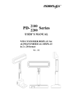
PD- 7100 Series 7200 USER’S MANUAL LCD CUSTOMER DISPLAY Rev. : A1 SOME IMPORTANT NOTES FCC NOTICE This equipment generates, uses, and can radiate radio frequency energy and, if not installed and used in accordance with the instructions manual, may cause interference to radio communications. It has been tested and found to comply with limits for a Class A digital device pursuant to subpart J of Part 15 of FCC Rules, which are designed to provide reasonable protection against interference when operated in a commercial environment. Operation of this equipment in a residential area is likely to cause interference in which case the user at his own expense will be required to take whatever measures to correct the interference. WARRANTY LIMITS Warranty will terminate automatically when the machine is opened by any person other than the authorized technicians. The user should consult his/her dealer for the problem happened. Warranty voids if the user does not follow the instructions in application of this merchandise. The manufacturer is by no means responsible for any damage or hazard caused by improper application. ABOUT THIS MANUAL This manual assists the user to utilize the LCD customer display PD-7100 / 7200 series. Both series provide versatile font formats and support various instruction sets. These series of products receive instructions in serial communication protocols and is capable of entering pass through mode so that all instructions received pass on to next connected serial device if properly configured. The manufacturer of the PD-7100 / 7200 series heartily apologizes to the user for reserving the right to change or to modify this manual without notice due to the rapid and constant progress and improvement on science and technology. The user may always obtain the most up to date information through any of our web sites: http://www.posiflex.com.tw, http: //www.posiflexuk.com, http://www.posiflexusa.com. Copyright Posiflex Inc. 2005 All rights are strictly reserved. No part of this documentation may be reproduced, stored in a retrieval system, or transmitted in any form or by any means, electronic, mechanical, photocopying, or otherwise, without the prior written consent of Posiflex Inc. the publisher of this documentation. TRADE MARKS AND SERVICE MARKS POSIFLEX is a registered trademark of Posiflex Inc.. Other brand and product names are trademarks and registered trademarks and service marks of their respective owners. P/N: 19440900020 TABLE OF CONTENTS GENERAL DESCRIPTION · · · · · · · · · · · · · · · · · · · · · 1 Introduction · · · · · · · · · · · · · · · · · · · · · · · · · 1 Application · · · · · · · · · · · · · · · · · · · · · · · · · · 1 Special Features · · · · · · · · · · · · · · · · · · · · · · · 1 Description · · · · · · · · · · · · · · · · · · · · · · · · · · 1 Model Numbers · · · · · · · · · · · · · · · · · · · · · · · 1 ACCESSORIES · · · · · · · · · · · · · · · · · · · · · INSTALLATION · · · · · · · · · · · · · · · · · · · · 2 3 Signal Connection · · · · · · · · · · · · · · · · · · · · · · 3 Power Connection · · · · · · · · · · · · · · · · · · · · · · 3 Using Power Adaptor · · · · · · · · · · · · · · · · · · · 3 Using Power from PC · · · · · · · · · · · · · · · · · · · 3 Using Power from POS System · · · · · · · · · · · · · · · 3 Using printer power adaptor · · · · · · · · · · · · · · · · 3 Connect for Pass Through Operation · · · · · · · · · · · · · 3 After Powering Up · · · · · · · · · · · · · · · · · · · · · · 3 - 1 1 1 1 2 2 - 1 - 1 1 1 1 1 3 3 3 4 OPERATION - 4 4 4 5 5 5 6 MECHANICAL SPECIFICATIONS · · · · · · ·4 - 1 - 1 - 1 ·······················3 Displaying Data · · · · · · · · · · · · · · · · · · · · · · · ·3 Command Codes · · · · · · · · · · · · · · · · · · · · · · · 3 DIP Switch & Jumper Settings · · · · · · · · · · · · · · · · 3 On control board in display head · · · · · · · · · · · · · · 3 On I/O board in base · · · · · · · · · · · · · · · · · · · · 3 Serial Data and Self Test · · · · · · · · · · · · · · · · · · · 3 Mechanical Drawings · · · · · · · · · · · · · · · · · · · · · 4 Mechanical Function · · · · · · · · · · · · · · · · · · · · · 4 ELECTRICAL CHARACTERISTICS ····· 5 Power ON/OFF Sequence · · · · · · · · · · · · · · · · · · · 5 Interface Signals · · · · · · · · · · · · · · · · · · · · · · · 5 i - 1 - 1 - 1 Normal Operation Ratings · · · · · · · · · · · · · · · · · · 5 - 1 OPTICAL CHARACTERISTICS · · · · · · · · · 5 - 1 - 1 - 2 Character Format · · · · · · · · · · · · · · · · · · · · · · 5 Fundamental Specification · · · · · · · · · · · · · · · · · · 5 ENVIRONMENTAL CHARACTERISTICS ii ·5 - 2 I. GENERAL DESCRIPTION A. Introduction This documentation describes the features and requirements of the product series of PD-7100 / 7200, a Liquid Crystal Display which is a wide customer display. It displays alphanumerical characters in 2 lines of 20 large sized characters and is able to display in 4 lines of 26 alphanumerical characters per line to show more information at a time. In this series, there are also models capable of displaying 2 lines of 10 oriental language characters per line in addition to the standard displaying capability. The alphanumerical characters are formed in a 8 x 16 dot matrix for 2 x 20 display and in a 6 x 8 dot matrix for 4 x 26 display, the oriental language characters are displayed in a format of 16 x 16 dot matrix. 2 x 20 4 x 26 2 x 10 Display Capacity Display Characters Alphanumerical Alphanumerical Oriental Language 6x8 16 x 16 Character Format 8 x 16 B. Application This unit may be used as a console display which provides alphanumeric information that is easily readable in wide range of ambient light. It is ideal for point-of-sale terminals, and a wide range of business and industrial equipment. C. Special features • • • • • • • • • • • Large character font size with backlight for easy readability Large amount of information display 3 different power supply choices Support pass through function on UART interface Wide operating temperature range (0°C to 50°C) 3 User defined characters (16 x 16 dot) US-ASCII Character (8 x 16 or 6 x 8 dot) Chinese GB or BIG-5 Character (16 x 16 dot) RS-232C data interface Software self test Versatile power source 1-1 D. Description This LCD is a self-contained multiplexed unit which provides a simple interface to a microprocessor system. The display is available with one I/O connector for both the RS232 interfacing and the power supply. This unit consists of a liquid crystal display cell and a minimal amount of electronic hardware. All display characters and control codes can be accessed in a 8-bit format. Primary complexity is contained within the microprocessor software, which controls all display functions. Data is entered serially at 9600 baud rate as default and can be changed to 19200 baud rate per jumper setting. The large characters are easily readable, and provide comfortable short or long-term viewing. E. Model numbers Model Number PD-7100/7200 PD-7110/7210 PD-7120/7220 16 x 16 or 8 x 16 16 x 16 or 8 x 16 Character Format 8 x 16 or 6 x 8 or 6 x 8 or 6 x 8 GB-Chinese or BIG-5-Chinese or Display Characters Alphanumerical Alphanumerical Alphanumerical 2 x 10 or 2 x 20 or 2 x 10 or 2 x 20 or Display Capacity 2 x 20 or 4 x 26 4 x 26 4 x 26 IEE or Epson or IEE or Epson or Command Set Epson or Noritake Noritake Noritake User-defined 3 characters max. 3 characters max. 3 characters max. Characters Standard model numbers carry footnote in form of “/X” to indicate the type of power adaptor. (ex. PD-7100/US) A model number without such indication in purchase order will indicate the PD and its signal cable only. A PD in this form can be applied with Posiflex POS system. For application with usual PC without power adaptor, please order the power kit to supply the PD. For application sharing power source with Posiflex POS printer, Please order the special power cable 20863250900. 1-2 II. • • • • ACCESSORIES User’s manual Pass through terminator (already plugged at bottom of PD) Signal cable 20863137210 (CCBLA-372) – a DB-9F to DB-9M RS232 cable 1.8 M Power source (one of the four below): Power adaptor specified per country type Power kit incl. power supply cable (inside PC) 39212001000 (CCBLA-141 on I/O plate) and power supply cable (to PD) 20863041100 (CCBLA-411) Combined in the signal cable mentioned above when the PD is connected to a Posiflex POS system Power cable (20863250900) to share from printer power adaptor 2-1 III. INSTALLATION A. Signal connection Connect the DB9 female connector of the signal cable CCBLA - 372 to the COM port of the host computer or POS system and connect the DB9 male connector of the signal cable CCBLA – 372 to the DB9 female connector in the base of the PD. B. Power connection 1. Using power adaptor Please place the base of the PD-7100/7200 series on a horizontal surface. Check that the power adaptor must meet the specification of the city power and then plug the adapter into city power outlet. Prepare to turn on the power switch at base of the PD. 2. Using power from PC Install the cable CCBLA-141 with I/O plate Switching Power in the power kit into the Supply Unit 4 pin Telephone hosting PC for obtaining Jack DC power as shown in the left drawing. However, it is absolutely important to turn all the power off before removing any case or connecting any cable. 4 pin Power Inside view of Followings are step-by-step CCBLA-141 connector instructions for installing example PC this cable. 1. Make sure the PC to supply power is turned off. 2. Open the case of PC according to its relevant manual. I/O Plate of CCBLA-141 3-1 3. Select one I/O plate position on rear window of PC to install the I/O plate of CCBLA-141. 4. Select one set of large 4 pin connector from the switching power supply unit of PC and connect the male 4 pin connector of CCBLA141 to the connector from power supply. Connect the female 4 pin connector of CCBLA-141 to the I/O device of PC such as a HDD if necessary. 5. Assemble the case of PC back. Then referring to drawing below to complete the basic power and signal cabling. Note the PC should remain OFF during the connection. 9 pin D connector of CCBLA-372 COM port (9 pin serial port) 4 pin Telephone jack of CCBLA-141 Both to bottom of PD 4 pin Telephone plug of CCBLA-411 Rear side of PC 1. Connect the 4 pin telephone plug of CCBLA-411 to the 4 pin telephone jack on the I/O plate of CCBLA-141 which has been mounted as described above. 2. Insert the DC plug of CCBLA-411 into the jack at the bottom of the base of PD in the same way as the power adaptor. Let the cables come out of the bottom of PD7100/7200 series through the opening at the back of base so that the PD can stand securely. 3. Now the user may turn on the PC and the PD for application unless the user wants to use PD for pass through purpose. 3-2 3. Using power from POS system This super convenient power supply method applies only when connected to a Posiflex POS system after proper setting for power in COM port. The power connection is already done when the signal connection is completed. 4. Using printer power adaptor Posiflex POS printer +24 V DC PD7000 +24 V DC Out +24 V DC In Posiflex POS Printer Power Adaptor (24 V DC) Power Cable (20863250900) The PD-7100/7200 series can also be powered by the power adaptor supporting a Posiflex POS printer by using a separately purchased specific power cable (P/N: 20863250900). Follow steps below: 1. Check that the (+24 V DC) power adaptor plug matches the power socket. But please always keep the insertion of the power adaptor into the power socket as the very last step of the whole installation procedure. 2. Insert the 3 pin power connector from the +24 V DC power adaptor to the “+24 V DC In” jack in the PD7000 connector area. Be sure to hear a click to obtain a firm contact. 3. Insert either end of the power cable (20863250900) to “+24 V DC Out” jack in the connector area and insert the other end to the power connector of Posiflex POS printer if needed. Be sure to hear a click at each connection to obtain a firm contact. 4. Now place the base on a horizontal surface and prepare to power on. 5. Please note that when DC power connection is used, there must be no AC power connection at the bottom of the base cabinet on the PD7000. C. Connect for Pass Through Operation In this series the jumper settings are internally set to pass through mode, while the PD is delivered with a COM port terminator on the 9 pin male connector at the bottom of PD. In this way, the PD serves the non-pass-through operation well. For pass through operation, the user has to merely remove this COM port terminator and connect the pass through connected device in stead. 3-3 Please reserve the COM port terminator in a safe place in case the non-passthrough operation would be required in the future. D. After Powering Up A firmware version as power on sign will appear on the screen for a while and the emulation mode will appear for a while after the firmware version display. Then a under-line cursor will appear at the left-most digit of the top row for Noritake and IEE emulation mode and no cursor will appear for other emulation modes. The installation is now completed. IV. OPERATION A. Displaying Data All data in 8-bit format received can be classified into 2 categories as data to display or command codes for the customer display unit to respond. For this series, unless under pass through mode or as part of the command code, any byte between and including <20>h and <FF>h is regarded as alphanumerical data to display according to ASCII table (the <XX>h means the hexadecimal expression). The command codes except the clear pass through flag command in Noritake mode always start with a byte between and including <00>h and <1F>h. For PD-7110/7120/7210/7220, the command codes follow the same rule as PD7100/7200, however, only those between and including <20>h and <7F>h are taken as alphanumerical data to display according to ASCII table in 8 x 16 format. Any two bytes with the first byte between and including <80>h and <FF>h are regarded as the expression for an oriental language character. When these two bytes fall off the content of the valid oriental language code table, an invalid character will be displayed. B. Command Codes For software command codes application. Please visit our web site http://www.posiflex.com.tw for details on software commands if required. 3-4 C. Dip Switch & Jumper Settings 1. On control board in display head Emulation mode (reach the switches from outside of back of the head) SW2 OFF ON SW1 OFF EPSON 2 X 20 NORITAKE 2 X 20 ON EPSON 4 X 26 IEE (CHINESE) 2 X 10 SW1 Push up to switch on SW2 RS232 protocol (Inside display head) Short JP1 19200, n, 8, 1 Open 9600, n, 8, 1 (default) 2. On I/O board in base Board layout J1 P4 P1 RS232 In RS232 Out CN1 JP1 JP2 1 4 1 S1 Posiflex POS system power supply: 1 – 2 Short JP1 +12 V DC for PST series (default) Hardware handshaking control: 3-5 3 –4 Short +5 V DC for TP series 1 –2 Short 2 –3 Short -Busy status of PD sent to host CTS, -Busy status of PD sent handshaking signal of pass through device JP2 to host as CTS and goes to host as DSR directly (default) DSR at the same time Note: There must be the pass through serial output device on the premounted pass through terminator connected to RS232 Out the 9 pin serial pass through port when JP2 is set to 2 –3 Short. Otherwise, the host computer may get a faulty condition in an attempt to write to this serial port. D. Serial Data and Self-test Serial characters are received with data formatted as a 10-bit word. The command set is structured to allow transmission of 8 data bits. The data rate is default at 9600 baud per second and can be changed to 19200 baud per second as described above. There is no parity bit and 1 stop bit. The level is RS-232C stop start b0 b1 b2 b3 b4 b5 b6 b7 bit bit Self-test is a very useful feature and can be activated by sending 1F-40 (HEX). The test may be terminated by sending 1B-40 (HEX). The test sequence is as follows a. b. c. d. e. Clear screen, Cursor home. Vertical scroll mode test, show product ID and version. For PD-7100/7200, it enters Overwrite mode and displays 20 characters of “A” followed by 20 characters of “B”. For PD-7110/7210 and PD-7120/7220, it enters Horizontal scroll mode test, and shows 20 CHINESE characters (addresses: B0A1, B1A2, B2A3, ……, BEAF, BFB0, C0B1, ……, C3B4) For PD-7100/7200, it enters Horizontal Scroll mode after clearing screen, then displays ASCII code font of current page from 21 to FF (HEX). For PD-7110/7210 and PD-7120/7220, it enters Wrap around mode and shows ASCII code font from 21 to 7F (HEX). Go to step a and repeat the test 3-6 V. MECHANICAL SPECIFICATIONS A. Mechanical Drawings 260.0 193.0 70.0 70.0 60.3 36.8 39.4 70.0 104.0 304.0 (Max. height) 200.0 200.0 104.0 Stroke (Lowest height) 41.0 41.0 41.0 220.0 110.0 B. Mechanical Function The pole of this customer display consists of 2 sections enabling adjustment on the height of the pole. The total height of this display is dependent on the pole adjustment, please refer to the drawings of last section The difference between maximal and minimal height is 104 mm. The display unit of this pole display can be rotated horizontally 359° and can also be slid horizontally. At the bottom of this display is a base where an on/off switch is and that the signal/power cable from the host computer and the cable to the pass through connected device can be connected to. The signal/power cable length between the base and the host computer is 1.8 M. This pole display offers 2 tilt angles 14.5° / 30° from vertical position. WARNING: If the user opens the pole display housing to make any change, all the product warranty will be voided. 4-1 VI. ELECTRICAL CHARACTERISTICS A. Power ON / OFF Sequence There are no deleterious effects associated with power ON and OFF of this display; however, rapid ON / OFF sequencing is not recommended. Neither data nor power connectors should be connected / disconnected while power is applied. B. Interface Signals All logic signals abide by the following convention: logic “1” is a “High”, logic “0” is a “Low”. C. Normal Operation Ratings Rated power dissipation: 3.75 W (max.) VII. OPTICAL CHARACTERISTICS A. CHARACTER FORMAT LANGUAGE FORMAT CHARACTER HEIGHT CHARACTER WIDTH CHARACTER SPACING CHARACTER DESIGN CURSOR INDICATOR CHARACTER SET CHINESE 2 lines of 10 characters 17.2 mm 16.75 mm 18.4 / 17.92 mm 16 x 16 dot matrix Under bar Chinese GB or BIG-5 5-1 ENGLISH & NUMERICAL 2 lines of 20 characters 17.2 mm 7.79 mm 18.4 / 8.96 mm 8 x 16 dot matrix Under bar ASCII B. FUNDAMENTAL SPECIFICATION Number of display dot Effective display area Dot size LCD type Viewing angle Response time : : : : : : 160 x 32 179.15 (W) x 36.75 (H) mm 1.07 (W) x 1.10 (H) mm STN with backlight 80 degrees vertically, 60 degrees horizontally 250 ms (typical) VIII. ENVIRONMENTAL CHARACTERISTICS Operating temperature: 0 to +50 (°C) Storage temperature: -20 to +70 (°C) Relative humidity: (≤40°C) 0 to 95 % (non-condensing) (≥40°C) Absolute humidity must be lower than the humidity of 95% RH at 40°C 5-2