1
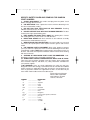
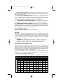
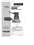
900006 - 02-07-02.qxd
10/15/02
2:25 PM
Page 1
ESPAÑOL: PÁGINA 15
FRANÇAISE : PAGE 29
Instruction
manual
Double Insulated
Random Orbit Sanders
MODEL
332
MODELS 333
and 334
MODEL
333VS
To learn more about Porter-Cable
visit our website at:
http://www.porter-cable.com
IMPORTANT
Please make certain that the person who
is to use this equipment carefully reads
and understands these instructions before
starting operations.
The Model and Serial No. plate is located on the main
housing of the tool. Record these numbers in the
spaces below and retain for future reference.
Model No. ______________________________________
Type ___________________________________________
Serial No. _______________________________________
Copyright © 2001 Porter-Cable Corporation
Part No. 900006 (02-07-02)
900006 - 02-07-02.qxd
10/15/02
2:25 PM
Page 2
WARNING: SOME DUST CREATED BY POWER SANDING, SAWING,
GRINDING, DRILLING, AND OTHER CONSTRUCTION ACTIVITIES
contains chemicals known to cause cancer, birth defects or other
reproductive harm. Some examples of these chemicals are:
· lead from lead-based paints,
· crystalline silica from bricks and cement and other masonry products, and
· arsenic and chromium from chemically-treated lumber.
Your risk from these exposures varies, depending on how often you do this
type of work. To reduce your exposure to these chemicals: work in a well
ventilated area, and work with approved safety equipment, such as those dust
masks that are specially designed to filter out microscopic particles.
GENERAL SAFETY RULES
WARNING: When using electric tools, basic safety precautions should
always be followed to reduce the risk of fire, electric shock and personal injury,
including the following:
SAVE THESE INSTRUCTIONS
WORK AREA
1. Keep your work area clean and well lit. Cluttered benches and dark
areas invite accidents.
2. Do not operate power tools in explosive atmospheres, such as in the
presence of flammable liquids, gases, or dust. Power tools create sparks
which may ignite the dust or fumes.
3. Keep bystanders, children, and visitors away while operating a
power tool. Distractions can cause you to lose control.
ELECTRICAL SAFETY
1. Double insulated tools are equipped with a polarized plug (one blade
is wider than the other). This plug will fit in a polarized outlet only one
way. If the plug does not fit fully in the outlet, reverse the plug. If it still
does not fit, contact a qualified electrician to install a polarized outlet. Do
not change the plug in any way. Double Insulation
eliminates the need
for the three wire grounded power cord and grounded power supply system.
2. Avoid body contact with grounded surfaces such as pipes, radiators,
ranges and refrigerators. There is an increased risk of electric shock if your
body is grounded.
3. Don’t expose power tools to rain or wet conditions. Water entering a
power tool will increase the risk of electric shock.
4. Do not abuse the cord. Never use the cord to carry the tools or pull
the plug from an outlet. Keep cord away from heat, oil, sharp edges or
moving parts. Replace damaged cords immediately. Damaged cords
increase the risk of electric shock.
5. When operating a power tool outside, use an outdoor extension cord
marked “W-A” or “W”. These cords are rated for outdoor use and reduce the
risk of electric shock.
PERSONAL SAFETY
1. Stay alert, watch what you are doing, and use common sense when
operating a power tool. Do not use tool while tired or under the influence
of drugs, alcohol, or medication. A moment of inattention while operating
power tools may result in serious personal injury.
2
900006 - 02-07-02.qxd
10/15/02
2:25 PM
Page 3
2. Dress properly. Do not wear loose clothing or jewelry. Contain long
hair. Keep your hair, clothing, and gloves away from moving parts. Loose
clothes, jewelry, or long hair can be caught in moving parts.
3. Avoid accidental starting. Be sure switch is OFF before plugging in.
Carrying tools with your finger on the switch or plugging in tools that have the
switch ON invites accidents.
4. Remove adjusting keys or wrenches before turning the tool ON. A
wrench or a key that is left attached to a rotating part of the tool may result in
personal injury.
5. Do not overreach. Keep proper footing and balance at all times.
Proper footing and balance enable better control of the tool in unexpected
situations.
6. Use safety equipment. Always wear eye protection. Dust mask, nonskid safety shoes, hard hat, or hearing protection must be used for
appropriate conditions.
TOOLS USE AND CARE
1. Use clamps or other practical way to secure and support the
workpiece to a stable platform. Holding the work by hand or against your
body is unstable and may lead to loss of control.
2. Do not force tool. Use the correct tool for your application. The
correct tool will do the job better and safer at the rate for which it is designed.
3. Do not use tool if switch does not turn it ON or OFF. A tool that cannot
be controlled with the switch is dangerous and must be repaired.
4. Disconnect the plug from the power source before making any
adjustments, changing accessories, or storing the tool. Such preventive
safety measures reduce the risk of starting the tool accidentally.
5. Store idle tools out of reach of children and other untrained persons.
Tools are dangerous in the hands of untrained users.
6. Maintain tools with care. Keep cutting tools sharp and clean. Properly
maintained tools, with sharp cutting edges are less likely to bind and are
easier to control.
7. Check for misalignment or binding of moving parts, breakage of
parts, and any other condition that may affect the tool’s operation. If
damaged, have the tool serviced before using. Many accidents are caused
by poorly maintained tools.
8. Use only accessories that are recommended by the manufacturer for
your model. Accessories that may be suitable for one tool may become
hazardous when used on another tool.
SERVICE
1. Tool service must be performed only by qualified repair personnel.
Service or maintenance performed by unqualified personnel may result in a
risk of injury.
2. When servicing a tool, use only identical replacement parts. Follow
instructions in the Maintenance Section of this manual. Use of
unauthorized parts or failure to follow Maintenance Instructions may create a
risk of electric shock or injury.
3
900006 - 02-07-02.qxd
10/15/02
2:25 PM
Page 4
SPECIFIC SAFETY RULES AND SYMBOLS FOR RANDOM
ORBIT SANDERS
1. ALWAYS DISCONNECT the sander cord plug from the power circuit
before changing abrasive sheets.
2. USE DUST MASK. Wear a protective mask to minimize breathing in the
fine dust created while sanding.
3. DO NOT RUN TOOL WITH BACK-UP PAD REMOVED. Resulting
vibration could cause loss of control.
4. DO NOT OPERATE TOOL WITH DUST SHROUD REMOVED. The dust
shroud covers high-speed rotating parts.
5. KEEP HANDS AND BODY PARTS AWAY from rotating disc. Contact
with rotating disc may cause severe cuts and abrasions.
6. NEVER RUN SANDER with dust container or dust collector assembly
removed. Dust could be blown into eyes.
7. WEAR EYE AND FACE PROTECTION. Injury to face and eyes can result
if disc flies off or pad ruptures. Wear impact resistant glasses and full face
shield.
8. USE PROPER SAFETY EQUIPMENT. Wear safety goggles to protect
your eyes and wear a protective mask to minimize breathing in the fine dust
created while sanding. NOTE: Some wood contains preservatives which can
be toxic. Take extra care to prevent inhalation and skin contact when working
with these materials.
9. SANDING OF LEAD-BASED PAINT IS NOT RECOMMENDED. Leadbased paint should only be removed by a professional.
10. SOME WOOD CONTAINS PRESERVATIVES WHICH CAN BE TOXIC.
Take extra care to prevent inhalation and skin contact when working with
these materials. Request, and follow, any safety information available from
your material supplier.
11.
WARNING: There are certain applications for which this tool was
designed. Porter-Cable strongly recommends that this tool NOT be modified
and/or used for any application other than for which it was designed. If you
have any questions relative to its application DO NOT use the tool until you
have written Porter-Cable and we have advised you.
Technical Service Manager
Porter-Cable Corporation
4825 Highway 45 North
Jackson, TN 38305
SYMBOL
V
A
Hz
W
kW
µF
l
kg
N/cm2
Pa
h
min
s
........................
........................
........................
........................
........................
........................
........................
........................
........................
........................
........................
........................
........................
DEFINITION
volts
amperes
hertz
watts
kilowatts
microfarads
liters
kilograms
newtons per square centimeter
pascals
hours
minutes
seconds
4
900006 - 02-07-02.qxd
10/15/02
2:25 PM
Page 5
........................ alternating current
3
........................ three-phase alternating current
3N
........................ three-phase alternating current with neutral
n0
........................ direct current
........................ no load
........................ alternating or direct current
........................ Class II Construction
........................ splash-proof construction
........................ watertight construction
…/min
........................ revolutions or reciprocation per minute
SAVE THESE INSTRUCTIONS
ADDITIONAL SAFETY RULES FOR PAINT REMOVAL
WARNING: Extreme care should be taken when removing paint. The
peelings, residue, and vapors of paint may contain lead, which is
poisonous. Exposure to even low levels of lead can cause irreversible
brain and nervous system damage; young and unborn children are
particularly vulnerable.
Before beginning any paint removal process you should determine whether the
paint you are removing contains lead. This can be done by your local health
department or by a professional who uses a paint analyzer to check for lead.
LEAD-BASED PAINT SHOULD ONLY BE REMOVED BY A PROFESSIONAL.
Persons removing paint should follow these guidelines:
1. KEEP THE WORK AREA WELL VENTILATED. Open the windows and
put an exhaust fan in one of them. Be sure the fan is moving air from inside to
outside.
2. REMOVE OR COVER any carpets, rugs, furniture, clothing, cooking
utensils and air ducts.
3. PLACE DROP CLOTHS in the work area to catch any paint chips or
peelings. Wear protective clothing such as extra work shirts, overalls and hats.
4. WORK IN ONE ROOM AT A TIME. Furnishings should be removed or
placed in the center of the room and covered. Work areas should be sealed
off from the rest of the dwelling by sealing doorways with drop cloths.
5. CHILDREN, PREGNANT OR POTENTIALLY PREGNANT women and
nursing mothers should not be present in the work area until the work is done
and all cleanup is complete.
6. WEAR A DUST RESPIRATOR or a dual filter (dust and fume) respirator
mask which has been approved by the Occupational Safety and Health
Administration (OSHA), the National Institute of Safety and Health (NIOSH), or
the United States Bureau of Mines. These masks and replaceable filters are
readily available at major hardware stores. Be sure the mask fits. Beards and
facial hair may keep the masks from sealing properly. Change filters often.
DISPOSABLE PAPER MASKS ARE NOT ADEQUATE.
5
900006 - 02-07-02.qxd
10/15/02
2:25 PM
Page 6
7. KEEP FOOD AND DRINK out of the work area. Wash hands, arms, and
face and rinse mouth before eating or drinking. Do not smoke or chew gum or
tobacco in the work area.
8. CLEAN UP ALL REMOVED PAINT and dust by wet mopping the floors.
Use a wet cloth to clean all walls, sills and any other surfaces where paint or
dust is clinging. DO NOT SWEEP, DRY DUST OR VACUUM. Use a high
phosphate detergent or trisodium (TSP) to wash and mop areas.
9. AT THE END OF EACH WORK SESSION put the paint chips and debris in
a double plastic bag, close it with tape or twist ties and dispose of properly.
10. REMOVE PROTECTIVE CLOTHING and work shoes in the work area to
avoid carrying dust into the rest of the dwelling. Wash work clothes separately.
Wipe shoes off with a wet rag that is then washed with the work clothes. Wash
hair and body thoroughly with soap and water.
REPLACEMENT PARTS
When servicing use only identical replacement parts.
MOTOR
Many Porter-Cable tools will operate on either D.C., or single phase 25 to 60
cycle A.C. current and voltage within plus or minus 5 percent of that shown
on the specification plate on the tool. Several models, however, are designed
for A.C. current only. Refer to the specification plate on your tool for proper
voltage and current rating.
CAUTION: Do not operate your tool on a current on which the
voltage is not within correct limits. Do not operate tools rated A.C.
only on D.C. current. To do so may seriously damage the tool.
EXTENSION CORD SELECTION
If an extension cord is used, make sure the conductor size is large enough to
prevent excessive voltage drop which will cause loss of power and
possible motor damage. A table of recommended extension cord sizes will be
found in this section. This table is based on limiting line voltage drop to 5 volts
(10 volts for 230 volts) at 150% of rated amperes.
If an extension cord is to be used outdoors it must be marked with the
suffix W-A or W following the cord type designation. For example – SJTW-A
to indicate it is acceptable for outdoor use.
Nameplate Ampere Rating
RECOMMENDED EXTENSION CORD SIZES FOR USE WITH PORTABLE ELECTRIC TOOLS
115V
230V
25 Ft.
50 Ft.
50 Ft.
100 Ft.
0-2
2-3
3-4
4-5
5-6
6-8
8-10
10-12
12-14
14-16
16-18
18-20
18
18
18
18
18
18
18
16
16
16
14
14
18
18
18
18
16
16
14
14
12
12
12
12
Length of Cord in Feet
100 Ft. 150 Ft. 200 Ft. 250 Ft.
200 Ft. 300 Ft. 400 Ft. 500 Ft.
18
16
16
14
14
12
12
10
10
10
8
8
16
14
14
12
12
10
10
8
8
8
8
6
6
16
14
12
12
10
10
8
8
6
6
6
6
14
12
12
10
10
8
8
6
6
6
4
4
300 Ft.
600 Ft.
14
12
10
10
8
6
6
6
6
4
4
4
400 Ft. 500 Ft.
800 Ft. 1000 Ft.
12
10
10
8
8
6
6
4
4
4
2
2
12
10
8
8
6
6
4
4
2
2
2
2
900006 - 02-07-02.qxd
10/15/02
2:25 PM
Page 7
FUNCTIONAL DESCRIPTION
FOREWORD
The Porter-Cable Random Orbit Sanders provide rapid stock removal with 80
to 100 grit paper and swirl-free finishing with 120-150 grit paper. Model 332 is
equipped to accept 5" diameter STIKIT™ adhesive paper backed abrasives.
Model 333 is equipped to accept 5" hook & loop backed abrasives with five
dust extraction holes. Model 333VS is equipped to accept 5" hook & loop
backed abrasives with five or eight dust extraction holes. Model 334 is
equipped to accept 5" diameter STIKIT™ adhesive backed abrasives with five
dust extraction holes.
TO START AND STOP SANDER
1. CAUTION: Make certain the switch is in the “OFF” position, and the
power source is the same as that specified on the tool’s nameplate.
2.
Connect the tool to the power source.
CAUTION: Keep hands and body parts away from rotating disc.
Contact with rotating disc can cause severe cuts and abrasions.
3. The switch button, (A) Fig. 1, is labeled “ON” and “OFF”. Depress the
“ON” end of the switch button to start motor. Depress the “OFF” end of the
switch button to stop motor.
SPEED CONTROL (333VS)
Model 333VS is equipped with a variable speed control. Operating speed is
adjustable between 5000 OPM (Orbits Per Minute) and 12000 OPM.
Adjust speed by turning thumbwheel (B) Fig. 1A. Thumbwheel position #1
provides the slowest operating speed (5000 OPM) and position #6 the fastest
(12000 OPM). Speed may be changed while motor is running or while it is
stopped.
B
A
A
Fig. 1
Fig. 1A
ASSEMBLY
INSTALLING/REMOVING ABRASIVE DISC
Models 332 and 334:
1.
2.
3.
CAUTION: DISCONNECT TOOL FROM POWER SOURCE.
Place machine on workbench with pad up (see Fig. 2).
Clean dust from pad face.
7
900006 - 02-07-02.qxd
10/15/02
2:25 PM
Page 8
Fig. 3
Fig. 2
4. Tear a new abrasive disc from roll and position disc to the sander pad.
Align the dust extraction holes in paper with holes in pad (334 ONLY).
5. Press disc firmly onto pad.
6. Position machine with abrasive contacting scrap material. Start machine
and operate momentarily while exerting firm pressure to seat disc to pad.
CAUTION: Failure to properly seat disc to pad may result in disc
being thrown from pad causing personal injury.
7.
To remove disc, peel disc away from pad.
NOTE: Do not store machine with an abrasive disc installed. Heat
generated by the sanding operation increases the adhesive bond
between the disc and pad. If disc is left on pad for an extended time
after use, it can become difficult to remove.
Models 333 and 333VS:
1. CAUTION: DISCONNECT TOOL FROM POWER SOURCE.
2. Place machine on workbench with pad up (see Fig. 3).
3. Clean dust from pad face.
4. Position Hook & Loop Abrasive Disc onto sander pad, aligning the dust
extraction holes in paper with holes in pad. NOTE: When using 8-hole
abrasive on model 333VS, align the hole pattern in the abrasive with the
groove in the sander pad.
CAUTION: Do not use PSA (Pressure Sensitive Adhesive) disc with
Hook & Loop pad as the disc may be thrown from the pad causing
personal injury.
5.
Press disc firmly onto pad.
CAUTION: Failure to properly seat disc to pad may result in disc
being thrown from pad causing personal injury.
6.
To remove disc, peel disc away from pad.
DUST COLLECTOR (Models 333, 333VS and 334)
1. CAUTION: DISCONNECT TOOL FROM POWER SOURCE.
2. Position dust collector to sander nozzle as shown in Fig. 4. Seat collector
onto nozzle.
8
900006 - 02-07-02.qxd
10/15/02
2:25 PM
Page 9
DUST
COLLECTOR
NOZZLE
Fig. 4
3. Periodically remove dust
container from flange and empty
collected dust, Fig. 5.
DUST
CONTAINER
NOTE: A slight twisting
action will ease removal and
reassembly.
Tap container lightly to remove
compacted dust. DO NOT WASH
CONTAINER. Dry compressed air
may be used to blow out
container.
FLANGE
Fig. 5
C A U T I O N : We a r s a f e t y glasses while using compressed air.
CAUTION: Never run sander with dust container or dust collector
assembly removed. Dust could be blown into eyes.
The dust collector can be rotated around the body of the sander. It may be
used in any convenient position, Fig. 6.
The dust collector may be replaced with Accessory Hose so that tool can be
used with a remote vacuum system.
Fig. 6
9
900006 - 02-07-02.qxd
10/15/02
2:25 PM
Page 10
OPERATION
HOW TO HOLD SANDER
These sanders are designed to be held either around the main housings, Fig.
7, or by the top of the main housings, Fig. 8. When sanding for long periods,
it is recommended you periodically alternate between the two holding
positions.
Fig. 7
Fig. 8
PAD BRAKE
These sanders are equipped with a pad brake that prevents over-speeding of
the pad. If the tool is lifted off the work surface while the motor is running, the
brake will limit pad rotation to no more than 400 RPM.
The pad brake uses a belt to provide the braking action. Eventually, this belt
may require replacement. If the brake fails to limit pad rotation, send the sander
to a Porter-Cable service facility or replace the belt yourself as explained under
BELT REPLACEMENT in the MAINTENANCE SECTION of this manual.
USING THE SANDER
1. CAUTION: Secure work to prevent it from moving during the sanding
operation. Friction between the sanding disc and work will try to spin work
away from sander and may cause bodily injury.
2.
CAUTION: WEAR SAFETY GLASSES AND DUST MASK.
3. Place sander pad in light contact with the work before switching the
motor “ON”.
4.
Grasp sander firmly and move switch to “ON” position.
5. Move sander in long overlapping strokes. Tipping sander or stopping in
one spot can produce an uneven finish.
6. When finished, keep pad in contact with work, move switch to “OFF”
position and lift sander from the work. Allow pad rotation to stop completely
before setting sander down.
10
900006 - 02-07-02.qxd
10/15/02
2:25 PM
Page 11
PAD
RETAINING
SCREWS
Fig. 9
CHANGING BACK-UP PAD
1.
CAUTION: DISCONNECT TOOL FROM POWER SOURCE.
2. Grasp pad with hand and use phillips screwdriver to remove three pad
retaining screws, Fig. 9 (turn screws counterclockwise to remove).
3.
Lift pad from sander.
4. Reverse procedure to install new pad. Tighten pad retaining screws 25 to
30 in-lbs.
MAINTENANCE
KEEP TOOL CLEAN
Periodically blow out all air passages with dry, compressed air. Remove
buildup of grime resulting from working with green or sappy wood. All plastic
parts should be cleaned with a soft damp cloth. NEVER use solvents to clean
plastic parts.
CAUTION: Wear safety glasses while using compressed air.
FAILURE TO START
Should your tool fail to start, check to make sure the prongs on the cord plug
are making good contact in the outlet. Also, check for blown fuses or open
circuit breakers in the line.
BRUSH INSPECTION AND LUBRICATION
For your continued safety and electrical protection, brush inspection and
replacement on this tool should ONLY be performed by an AUTHORIZED
PORTER-CABLE SERVICE STATION or a PORTER-CABLE/DELTA FACTORY
SERVICE CENTER.
At approximately 100 hours of use, take or send your tool to your nearest
authorized Porter-Cable Service Station to be thoroughly cleaned and
inspected. Have worn parts replaced and lubricate with fresh lubricant. Have
new brushes installed, and test the tool for performance.
Any loss of power before the above maintenance check may indicate the need
for immediate servicing of your tool. DO NOT CONTINUE TO OPERATE TOOL
UNDER THIS CONDITION. If proper operating voltage is present, return your
tool to the service station for immediate service.
11
BELT REPLACEMENT
1. CAUTION: DISCONNECT TOOL FROM POWER SOURCE.
2. Remove back-up pad (see CHANGING BACK-UP PAD).
3. Remove the old belt and clean the belt mounting area.
4. Position the new belt around pulley (A) Fig. 10, and start it onto the
shoulder of the pad support (B).
5. Rotate the pad support as you “walk” the belt onto it (see Fig. 11).
6. Reassemble back-up pad (see CHANGING BACK-UP PAD).
SERVICE AND REPAIRS
All quality tools will eventually require servicing or replacement of parts due to
wear from normal use. These operations, including brush inspection and
replacement, should ONLY be performed by either an AUTHORIZED
PORTER-CABLE SERVICE STATION or a PORTER-CABLE/DELTA FACTORY
SERVICE CENTER. All repairs made by these agencies are fully guaranteed
against defective material and workmanship. We cannot guarantee repairs
made or attempted by anyone other than these agencies.
Should you have any questions about your tool, feel free to write us at any
time. In any communications, please give all information shown on the
nameplate of your tool (model number, type, serial number, etc.).
ACCESSORIES
A complete line of accessories is available from your Porter-Cable
12
900006 - 02-07-02.qxd
10/15/02
2:25 PM
Page 13
PORTER-CABLE LIMITED
ONE YEAR WARRANTY
Porter-Cable warrants its Professional Power Tools for a period of one year from the date of original
purchase. We will repair or replace at our option, any part or parts of the product and accessories
covered under this warranty which, after examination, proves to be defective in workmanship or
material during the warranty period. For repair or replacement return the complete tool or accessory,
transportation prepaid, to your nearest Porter-Cable Service Center or Authorized Service Station.
Proof of purchase may be required. This warranty does not apply to repair or replacement required
due to misuse, abuse, normal wear and tear or repairs attempted or made by other than our Service
Centers or Authorized Service Stations. NOTE: THIS WARRANTY WILL BE VOID IF THE TOOL IS
USED ON DRYWALL.
ANY IMPLIED WARRANTY, INCLUDING THE IMPLIED WARRANTIES OF MERCHANTABILITY AND
FITNESS FOR A PARTICULAR PURPOSE, WILL LAST ONLY FOR ONE (1) YEAR FROM THE DATE
OF PURCHASE.
To obtain information on warranty performance please write to: PORTER-CABLE CORPORATION,
4825 Highway 45 North, Jackson, Tennessee 38305; Attention: Product Service. THE FOREGOING
OBLIGATION IS PORTER-CABLE’S SOLE LIABILITY UNDER THIS OR ANY IMPLIED WARRANTY
AND UNDER NO CIRCUMSTANCES SHALL PORTER-CABLE BE LIABLE FOR ANY INCIDENTAL OR
CONSEQUENTIAL DAMAGES. Some states do not allow limitations on how long an implied warranty
lasts or the exclusion or limitation of incidental or consequential damages, so the above limitation or
exclusion may not apply to you.
This warranty gives you specific legal rights and you may also have other legal rights which vary from
state to state.
13
900006 - 02-07-02.qxd
10/15/02
2:25 PM
Page 14
NOTES
14