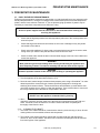
1
Model #: ___________________________ Serial #: ___________________________ Date Purchased: ____________________ Installation & Operation Manual SSPG14: Floor Model Gas Pasta Cooker SSRS14: Floor Model Rinse Station C E E S I G N D D CERT I F I ED E R T I F I L20-331, rev.02 (08/11) ENGLISH IMPORTANT FOR FUTURE REFERENCE Please complete this information and retain this manual for the life of the equipment: TO THE PURCHASER, OWNER AND STORE MANAGER Please review these warnings prior to posting them in a prominent location for reference. TO THE PURCHASER WARNING Post in a prominent location the instructions to be followed in the event that an operator smells gas. Obtain this information from your local gas supplier. WARNING DO NOT store or use gasoline or other flammable vapors and liquids in the vicinity of this or any other appliance. WARNING Improper installation, alteration, service or maintenance can cause property damage, injury or death. Read the installation, operating and maintenance instructions thoroughly before installing or servicing this appliance. WARNING Installation, maintenance and repairs should be performed by a Pitco Authorized Service and Parts (ASAP) company technician or other qualified personnel. Installation, maintenance or repairs by an unauthorized and unqualified personnel will void the warranty. The appliance is NOT jet stream approved. DO NOT clean the appliance with a water jet. WARNING DO NOT attempt to move this appliance or transfer hot liquids from one container to another when the unit is at operating temperature or filled with hot liquids. Serious personal injury could result if skin comes in contact with the hot surfaces or liquids. WARNING DO NOT sit or stand on this appliance. The appliance’s front panel, tank, splash back, tank cover, workshelf, drain board is not a step. Serious injury could result from slipping, falling or contact with hot liquids. WARNING NEVER use the appliance as a step for cleaning or accessing the ventilation hood. Serious injury could result from slips, trips or from contacting hot liquids. WARNING WARNING Installation and all connections must be made according to national and local regulations and codes in force. WARNING During the warranty period if a customer elects to use a nonoriginal part or modifies an original part purchased from Pitco and/or its Authorized Service and Parts (ASAP) companies, this warranty will be void. In addition, Pitco and its affiliates will not be liable for any claims, damages or expenses incurred by the customer which arises directly or indirectly, in whole or in part, due to the installation of any modified part and/or received from an unauthorized service center. WARNING This appliance, when installed, must be electrically grounded in accordance with local codes, or in the absence of local codes, with the National Electrical Code, ANSI/NFPA 70, or the Canadian Electrical Code, CSA C22.2, as applicable. WARNING Adequate means must be provided to LIMIT the movement or this appliance without depending on the gas or electrical cord connection. Single appliances equipped with legs must be stabilized by installing anchor straps. All appliances equipped with casters must be stabilized by installing restraining chains. The water level should be maintained at the level line. DO NOT turn the appliance on until the heat tubes are fully covered with water at all times. Serious injury could result from hot steam vapors off the heat tubes. WARNING If overflow drain is not equipped or if overflow drain stop is used, do not leave appliance unattended while filling with water. Over filling the appliance can cause serious injuries and damage the equipment. WARNING Completely shut the appliance down when the water is being drained from the appliance. This will prevent the appliance from heating up during the draining and filling process. Serious injury can occur. WARNING This appliance is intended for indoor use only. WARNING DO NOT operate appliance unless all panels and access covers are attached correctly. WARNING It is recommended that this appliance be inspected by a qualified service technician for proper performance and operation on a yearly basis. WARNING In North America an appliance equipped with casters and a flexible gas line must be connected to the gas supply with a quick disconnect device. This quick disconnect must comply with ANSI Z24.41. WARNING There is an open flame inside this appliance. The unit may get hot enough to set nearby materials on fire. Keep the area around the appliance free from combustibles. WARNING WARNING DO NOT alter or remove structural material on the appliance to accommodate placement under a ventilation hood. WARNING This appliance is not intended for persons (including children) with reduced physical, sensory or mental capabilities, or lack of experience or knowledge, unless they have been given supervision or instruction concerning use of the appliance by a person responsible for their safety. Do not allow children to operate, or play on or around the appliance. WARNING If the appliance is equipped with a power cord and it is damaged, it must be replaced by a Pitco Authorized Service and Parts (ASAP) company technician, or a similarly qualified person in order to avoid a hazard. DO NOT supply the appliance with a gas that is not indicated on the data plate. If you need to convert the appliance to another type of fuel, contact your dealer. WARNING DO NOT use an open flame to check for gas leaks! WARNING If gas flow to appliance is interrupted, or pilots extinguish, wait 5 minutes before attempting to relight the pilot to allow any residual gas in appliance to dissipate. WARNING Ensure that the appliance can get enough air to keep the flame burning correctly. If the flame is starved for air, it can give off a dangerous carbon monoxide gas. Carbon monoxide is a clear odorless gas that can cause suffocation. WARNING The power supply must be disconnected before servicing, maintaining or cleaning this appliance. ii L20-331, rev.02 (08/11) SSPG14: Floor Model High Efficiency Gas Pasta Cooker TABLE OF CONTENTS 1. INSTALLATION ........................................................................................................ 1 1.1. CHECKING YOUR NEW APPLIANCE ........................................................................................................1 1.2. INSTALLATION CLEARANCES .................................................................................................................2 1.3. LEG/CASTER INSTALLATION AND LEVELING .......................................................................................3 1.4. PLUMBING CONNECTIONS.......................................................................................................................4 1.4.1. 1.4.2. 1.5. WATER INLET CONNECTIONS ..........................................................................................................4 DRAIN CONNECTIONS .......................................................................................................................4 GAS CONNECTION ....................................................................................................................................5 1.5.1. 1.5.2. 1.5.3. 1.5.4. QUICK DISCONNECT CONNECTION ................................................................................................5 FUEL SUPPLY LINE LEAK AND PRESSURE TESTING ....................................................................5 CE GAS TABLE ....................................................................................................................................6 NON CE GAS TABLE ...........................................................................................................................7 1.6. ELECTRICAL CONNECTIONS ...................................................................................................................8 1.7. VENTILATION AND FIRE SAFETY SYSTEMS ..........................................................................................8 1.8. INSPECTION ...............................................................................................................................................9 1.9. INITIAL ADJUSTMENTS .......................................................................................................................... 10 1.9.1. 1.9.2. 1.9.3. 1.9.4. 1.9.5. 1.10. FILLING THE APPLIANCE ................................................................................................................ 10 LIGHTING INSTRUCTIONS .............................................................................................................. 10 SELF CLEANING BURNER SYSTEM .............................................................................................. 11 PILOT FLAME ADJUSTMENT .......................................................................................................... 11 MAIN BURNER SYSTEM ADJUSTMENT ......................................................................................... 12 INITIAL CLEANING .............................................................................................................................. 13 2. OPERATION ........................................................................................................... 14 2.1. OPERATIONAL FEATURES .................................................................................................................... 14 2.2. FILLING THE APPLIANCE ....................................................................................................................... 16 2.2.1. 2.2.2. FILLING THE COOKER TANK .......................................................................................................... 16 FILLING THE RINSE TANK............................................................................................................... 16 2.3. APPLIANCE START UP ........................................................................................................................... 16 2.4. COOKING ................................................................................................................................................. 17 2.4.1. 2.4.2. 2.4.3. 2.4.4. 2.4.5. 2.4.6. 2.4.7. 2.5. SIMMER MODE ................................................................................................................................. 17 BOIL MODE ....................................................................................................................................... 17 TIMER OPERATION.......................................................................................................................... 17 BASKET LIFT OPERATION .............................................................................................................. 17 ADDITIONAL CONTROLLER FUNCTIONS...................................................................................... 17 MANUAL WATER FILL ...................................................................................................................... 18 COOKING TIPS ................................................................................................................................. 18 APPLIANCE SHUTDOWN ....................................................................................................................... 18 2.5.1. 2.5.2. STANDBY MODE .............................................................................................................................. 18 COMPLETE SHUTDOWN ................................................................................................................. 18 3. PREVENTATIVE MAINTENANCE .......................................................................... 19 L20-331, rev.02 (08/11) iii TABLE OF CONTENTS 3.1. DAILY PREVENTATIVE MAINTENANCE ............................................................................................... 19 3.1.1. 3.1.2. 3.1.3. 3.2. APPLIANCE INSPECTION ................................................................................................................ 19 CLEANING THE COOK TANK (RINSE TANK IF EQUIPPED) ......................................................... 19 CLEANING THE CABINET ................................................................................................................ 19 MONTHLY PREVENTATIVE MAINTENANCE ........................................................................................ 20 3.2.1. 3.3. DE-LIMING ........................................................................................................................................ 20 ANNUAL/PERIODIC PREVENTATIVE MAINTENANCE AND INSPECTION ......................................... 20 3.3.1. 3.3.2. 3.3.3. 3.3.4. 3.3.5. 3.3.6. 3.4. TEMPERATURE PROBE & HIGH LIMIT PROBE ............................................................................. 20 CONTROLLER .................................................................................................................................. 20 CONTROL BOX & ELECTRICAL COMPONENTS ........................................................................... 20 TANK.................................................................................................................................................. 21 DRAIN SYSTEM ................................................................................................................................ 21 GAS COMBUSTION SYSTEM .......................................................................................................... 21 VENTILATION HOOD ............................................................................................................................... 21 4. TROUBLESHOOTING ............................................................................................ 22 4.1. POWER FAILURE .................................................................................................................................... 22 4.2. HIGH TEMPERATURE LIMIT SWITCH .................................................................................................... 22 4.2.1. 4.2.2. Cook Tank Temperature Limit Switch ................................................................................................ 22 Self Cleaning Burner System Temperature Limit Switch................................................................... 22 4.3. DRAIN VALVE INTERLOCK .................................................................................................................... 22 4.4. TROUBLESHOOTING CHART ................................................................................................................ 23 4.5. CONTROLLER WARNING DISPLAYS .................................................................................................... 23 iv L20-331, rev.02 (08/11) INSTALLATION SSPG14: Floor Model High Efficiency Gas Pasta Cooker 1. INSTALLATION 1.1. CHECKING YOUR NEW APPLIANCE Your new Pitco appliance has been carefully packed into one crate. Every effort has been made to ensure that it is delivered to you in perfect condition. As you unpack your new appliance, inspect each of the pieces for damage. If something is damaged, DO NOT sign the bill of lading. Contact the shipper immediately; the shipper is only responsible for 15 days after delivery. Check the packing list enclosed with your appliance to ensure that you have received all the parts to the appliance. If you are missing any parts, contact the dealer from whom the appliance was purchased. As you unpack the appliance and its accessories be careful to keep the weight of the appliance evenly distributed. Refer to the table below to identify which accessories should be included with your appliance. Locate your Pitco model number and serial number on the inner door of the appliance and the find the date purchased. Write this information on the front cover of this manual for future reference. If you have completed the above steps that are applicable to the appliance you purchased, the appliance is now ready to be installed. Although it may be possible for you to install and set up your new appliance, it is STRONGLY recommended that you have this done by qualified professionals. A qualified professional will ensure that the installation is safe and meets local building and fire codes. Accessories ITEM DESCRIPTION SSPG14 SSRS14 1 Basket Hanger Standard Standard 2 Tube Rack Standard N/A 3 Drain Cleanout Rod Standard Standard 4 Small Bulk Pasta Basket Optional Optional 5 Large Bulk Pasta Basket Optional Optional 6 Small Round Pasta Basket Optional Optional 7 Large Round Pasta Basket Optional Optional 8 Oblong Pasta Basket Optional Optional 9 Individual Portion Cups/Rack Optional Optional L20-331, rev.02 (08/11) 1 INSTALLATION WARNING DO NOT sit or stand on this appliance. The appliance’s front panel, tank, splash back, tank cover, workshelf, drain board is not a step. Serious injury could result from slipping, falling or contact with hot liquids. 1.2. INSTALLATION CLEARANCES The clearances shown below are for combustible and non-combustible installations and will allow for safe and proper operation of your appliance. Unit Combustible Construction Inches (centimeters) Non-Combustible Construction Inches (centimeters) Back Sides 6.0" (15.24cm) 6.0" (15.24cm) 0.0" (0.0cm) 0.0" (0.0cm) In addition to the above clearances there must also be at least 16 inches (40.64cm) of aisle space in front of the unit. WARNING DO NOT obstruct the flow of ventilation or air openings around the appliance. Adequate clearance around the appliance is necessary for servicing and proper component ventilation. Ensure that you meet the minimum clearance requirements specified in this manual. WARNING DO NOT install this appliance next to a deep fat fryer. A splash over of water into the hot oil may cause a flash fire. CAUTION To prevent equipment damage and/or personal injury, do not tilt the appliance onto any two of its casters or legs, or pull the appliance by the splash back. 2 L20-331, rev.02 (08/11) SSPG14: Floor Model High Efficiency Gas Pasta Cooker INSTALLATION 1.3. LEG/CASTER INSTALLATION AND LEVELING When you receive your appliance it is completely assembled with the possible exception of the legs (or casters). This appliance must be installed with legs or casters; it cannot be curb mounted. Curb mounting will seriously inhibit this appliance’s ability to effect proper component ventilation. The legs/casters must be installed before connecting the appliance to the gas supply. The legs provide the necessary height to meet sanitation requirements and assure adequate air supply to the combustion system. Use the following procedure Required tools: 7/16 “ wrench and socket and a large pair of water pump pliers. 1. Remove all loose accessories and carefully place the appliance on its back to avoid damage to the cabinet and splash back. Protect the outside of the appliance with cardboard or a drop cloth when laying it down. Take care not to pinch any electrical cords between the cabinet and the floor. 2. Attach each leg/caster with the hex head screws and nuts supplied. Each leg/caster requires four 1/4-20 x 5/8” hex head screws and nuts. Insure that all screws are tight. 3. Mount the screws from the inside of the appliance with the nut on the outside (bottom, see diagram below) of the appliance. The nuts have lock washers attached to them, therefore it is not necessary to use separate lock washers. 4. When all four legs/casters are securely mounted, stand the unit upright, being careful not to put too much weight on any one leg or caster. Adjust the height and level the appliance by adjusting the leveling devices (B) with water pump pliers. Rotating the leveling device in a Clockwise (CW) direction will reduce the height of the appliance, Counter Clockwise rotation will increase the height of the appliance. For casters, loosen 2 set screws (A) before leveling, adjust the height, then retighten. WARNING This appliance must be installed with the legs or casters provided by the manufacturer. WARNING DO NOT install legs or casters, or perform leveling procedure when appliance is in operation or full of hot liquids. Serious injury could result. L20-331, rev.02 (08/11) 3 INSTALLATION 1.4. PLUMBING CONNECTIONS The plumbing installation should be done by a licensed plumber and must comply with local and national codes. The instructions for appliances connected to the water mains by detachable hose sets shall state that new hose sets will be used and that the old hose sets should not be reused (if applicable). 1.4.1. WATER INLET CONNECTIONS If your appliance is equipped with a faucet or a water fill option connections to a potable water supply will be required. If a single water connection is required it is recommended that the appliance is connected to hot water supply. This will greatly decrease the time and energy required for the appliance to reach operating temperature. Prior to installation, a water treatment specialist should inspect the water supply. Water hardness should contain no more then 2.0 grains/gallon. The pH level should be between 6.5 and 8.0. These conditions can be obtained with the use of a properly maintained water softener. The incoming water pressure should be between 20 psi (138 kPa) to 60 psi (414 kPa). For higher water pressures, a high-pressure regulator must be installed to inlet plumbing to avoid damage caused by water hammer. The maximum allowable incoming water temperature is 180°F (82°C). Have your water tested and record the measured values below. WARNING When water is at a high temperature and high pressure, excessive splashing of hot water may occur that could result in injury. Temperature Hardness pH Pressure Water Quality Checklist Measured Max Limit or Range 180°F (82°C) Max. 2.0 Grains/Gal. Max. 6.5 to 8.0 20 psi (138 kPa) to 60 psi (414 kPa) OK 1.4.2. DRAIN CONNECTIONS Each tank has a drain that can be connected to a drainage system. Each tank also has an overflow line. The overflow connection is after the drain valve to provide an unobstructed overflow path. The tank drain and overflow line for each tank is connected together to form a common drain line. When there are more than 2 appliances joined together the common drains can be connected together with a manifold that has a 1-1/4” NPT outlet connection. The outlet on the can be mounted so it can drain under the left or right hand unit. 4 L20-331, rev.02 (08/11) SSPG14: Floor Model High Efficiency Gas Pasta Cooker INSTALLATION 1.5. GAS CONNECTION Your appliance will give you peak performance when the gas supply line is of sufficient size to provide the correct gas flow. The gas line must be installed to meet the local building codes or National Fuel Gas Code ANS Z223.1 and NFPA 54 (latest editions). In Canada, install the appliance in accordance with CSA B149.1 or .2 and local codes. Gas line sizing requirements can be determined by a qualified installation professional, your local gas company or by referring to the National Gas Fuel Code, Appendix C, Table C-4 (for natural gas) and Table C-16 (for propane). The gas line needs to be large enough to supply the necessary amount of fuel to all appliances without losing pressure to any appliance. A properly sized and installed gas line will deliver a supply pressure between 7.0” W.C. (17.4 mbars, 1.74 kPa) and 10.0” W.C. (24.9 mbars, 2.49 kPa) natural gas or between 11.0” W.C. (27.4 mbars, 2.74 kPa) and 13.0” W.C. (32.4 mbars, 3.25 kPa) propane to all appliances connected to the supply line, operating simultaneously at full demand. The pressure at the gas valve must not exceed 1/2 PSI. Each appliance is equipped to operate on one certain fuel type. The type of fuel with which the appliance is intended to operate is stamped on the data plate, which is attached to the inside of the door. WARNING NEVER supply the appliance with a gas other than the one that is indicated on the data plate. Using the incorrect gas type will cause improper operation and could result in serious injury or death. If you need to convert the appliance to another type of fuel, contact the dealer you purchased it from. NOTICE NEVER use an adapter to make a smaller gas supply line fit the appliance connection. This may not allow proper gas flow for optimum burner operation, resulting in poor performance and improper operation. 1.5.1. QUICK DISCONNECT CONNECTION In North America gas appliances equipped with casters must be installed with connectors that comply with the Standard for Movable Gas Appliances, ANSI Z21.69 • CSA 6.16 latest edition. This connection should include a quick disconnect device that complies with the Standard for Quick Disconnect Devices for Use With Gas Fuel, ANSI Z21.41 • CSA 6.9 latest edition. When installing the appliance you must also install adequate means for limiting the movement of the appliance without depending on the connector or quick-disconnect device or it’s associated piping to limit the movement of the appliance. The restraining device should be attached to the appliance on the back panel. 1.5.2. FUEL SUPPLY LINE LEAK AND PRESSURE TESTING The fuel supply system must be tested before the appliance is used. If the fuel line is going to be tested at a pressure greater than 1/2 PISG (3.45 kPa), insure that that appliance is disconnected from the fuel line. If the fuel line is to be tested at a pressure equal to or less than 1/2 PSIG (3.45 kPa), the appliance can be connected during the test, but the unit’s gas valve must be shut. Test all gas line connections for leaks with leak detection solution, or a solution of soap and water when pressure is applied. L20-331, rev.02 (08/11) 5 INSTALLATION * Natural gas models for Belgium require a 3.45 mm restrictor orifice. Continued on next page…… 6 L20-331, rev.02 (08/11) Nom rate (M3/HR) Pilot Orifice Burner Orifice Burner Pressure (mbar) Supply Pressure (mbar) Input Net (kW) 17.5 15.8 20 10 2.05 mm N22 MODEL NOT APPROVED FOR USE WITH LP GAS 15.8 20/25 10 2.05/2.25 mm N22 17.5 16.1 50/37 25.4 1.25 mm LP16 15.8 20 10 2.05 mm N22 17.5 16.1 50/37 25.4 1.25 mm LP16 15.8 20 10 2.05 mm N22 17.5 16.1 50/37 25.4 1.25 mm LP16 THIS COUNTRY DOES NOT USE NATURAL GAS 17.6 16.1 50/37 25.4 1.25 mm LP16 15.8 20 10 2.05 mm N22 17.5 16.1 50/37 25.4 1.25 mm LP16 15.8 20/25 10 2.05/2.25 mm N22 17.5 16.1 50/37 25.4 1.25 mm LP16 17.5 15.8 20 10 2.05 mm N22 MODEL NOT APPROVED FOR USE WITH LP GAS 17.5 15.8 20 10 2.05 mm N22 MODEL NOT APPROVED FOR USE WITH LP GAS 15.8 20 10 2.05 mm N22 17.5 16.1 50/37 25.4 1.25 mm LP16 17.5 15.8 20 10 2.05 mm N22 MODEL NOT APPROVED FOR USE WITH LP GAS 15.8 20/25 10 2.05/2.25 mm N22 17.5 16.1 50/37 25.4 1.25 mm LP16 15.8 20 10 2.05 mm N22 17.5 16.1 50/37 25.4 1.25 mm LP16 15.8 20 10 2.05 mm N22 17.5 16.1 50/37 25.4 1.25 mm LP16 15.8 20 10 2.05 mm N22 17.5 16.1 50/37 25.4 1.25 mm LP16 Governor NAT G20 I2H LP NAT G20/G25 I2E+ BE* LP G31 I3P NAT G20 I2H BG LP G31 I3P NAT G20 I2H CH LP G31 I3P NAT CY LP G31 I3P NAT G20 I2H CZ LP G31 I3P NAT G20/G25 I2ELL DE LP G31 I3P NAT G20 I2H DK LP NAT G20 I2H EE LP NAT G20 I2H ES LP G31 I3P NAT G20 I2H FI LP NAT G20/G25 I2Esi FR LP G31 I3P NAT G20 I2H GB LP G31 I3P NAT G20 I2H GR LP G31 I3P NAT G20 I2H HU LP G31 I3P AT Input Gross (kW) Appliance Category Gas Fuel Type Country 1.5.3. CE GAS TABLE Refer to the following table for gas specifications for the country of use. If the country of use is NOT listed, refer to the information stamped on the data plate. YES 1.7 NO YES YES YES YES YES 1.7/1.9 0.7 1.7 0.7 1.7 0.7 YES YES YES YES YES YES 0.7 1.7 0.7 1.7/1.9 0.7 1.7 YES 1.7 YES YES YES 1.7 0.7 1.7 YES YES YES YES YES YES YES YES 1.7/1.9 0.7 1.7 0.7 1.7 0.7 1.7 0.7 INSTALLATION SSPG14: Floor Model High Efficiency Gas Pasta Cooker LV MT NL NO PL PT RO SE SI SK TR 1.5.4. I2H I3P I2H I3P I2H I3P I2H G20 G31 G20 G31 G20 G31 I2H I3P I2H I3P I2H I3P Pilot Orifice G20 G31 G20 G31 G20 G31 G20 Burner Orifice I3P I2L I3P I2H Burner Pressure (mbar) G31 G25 G31 G20 Supply Pressure (mbar) I2E I3P I2H Input Net (kW) G20 G31 G20 Input Gross (kW) I2H I3P I2H I3P I2H 15.8 20 10 2.05 mm N22 16.1 50/37 25.4 1.25 mm LP16 15.8 20 10 2.05 mm N22 17.5 16.1 50/37 25.4 1.25 mm LP16 17.5 15.8 20 10 2.05 mm N22 MODEL NOT APPROVED FOR USE WITH LP GAS 15.8 20 10 2.05 mm N22 17.5 16.1 50/37 25.4 1.25 mm LP16 17.5 15.8 20 10 2.05 mm N22 MODEL NOT APPROVED FOR USE WITH LP GAS THIS COUNTRY DOES NOT USE NATURAL GAS 17.5 16.1 50/37 25.4 1.25 mm LP16 15.8 25 10 2.25 mm N22 17.5 16.1 50/37 25.4 1.25 mm LP16 17.5 15.8 20 10 2.05 mm N22 MODEL NOT APPROVED FOR USE WITH LP GAS 15.8 20 10 2.05 mm N22 17.5 16.1 50/37 25.4 1.25 mm LP16 15.8 20 10 2.05 mm N22 17.5 16.1 50/37 25.4 1.25 mm LP16 15.8 20 10 2.05 mm N22 17.5 16.1 50/37 25.4 1.25 mm LP16 17.5 15.8 20 10 2.05 mm N22 MODEL NOT APPROVED FOR USE WITH LP GAS 15.8 20 10 2.05 mm N22 17.5 16.1 50/37 25.4 1.25 mm LP16 15.8 20 10 2.05 mm N22 17.5 16.1 50/37 25.4 1.25 mm LP16 15.8 20 10 2.05 mm N22 17.5 16.1 50/37 25.4 1.25 mm LP16 17.5 Nom rate (M3/HR) LU G20 G31 G20 G31 G20 Governor LT Appliance Category IT NAT LP NAT LP NAT LP NAT LP NAT LP NAT LP NAT LP NAT LP NAT LP NAT LP NAT LP NAT LP NAT LP NAT LP NAT LP Gas IE Fuel Type Country CE Gas table Continued YES YES YES YES YES 1.7 0.7 1.7 0.7 1.7 YES YES YES 1.7 0.7 1.7 YES YES YES YES 0.7 1.9 0.7 1.7 YES YES YES YES YES YES YES 1.7 0.7 1.7 0.7 1.7 0.7 1.7 YES YES YES YES YES YES 1.7 0.7 1.7 0.7 1.7 0.7 NON CE GAS TABLE NON CE Gas Information Table Natural Gas Propane(LP) Gas 7" WC 11" WC Supply Pressure Burner Pressure 4" WC 10" WC Main Burner Orifice #46 dms #55 dms L20-331, rev.02 (08/11) 7 INSTALLATION 1.6. ELECTRICAL CONNECTIONS It is advised that this appliance be plugged into a wall receptacle that is controlled by the ventilation control. This will prevent the appliance from being operated without the ventilator on. If your appliance requires an electrical connection, the power requirements are listed below. Input Voltage Current/Unit Electrical Requirements North America International 120 VAC, 50/60 Hz 220,230 or 240 VAC, 50/60 Hz 1.0 Amp(s) 0.5 Amp(s) CAUTION Connecting the appliance to the wrong power supply may damage the appliance and void the warranty. WARNING DO NOT attempt to connect the appliance to an electrical supply other then that indicated on the data plate. WARNING The electrical connection used by this appliance must comply with local codes. If there are no local codes that apply, refer to the National Electrical Code (NEC), ANSI/NFPA 70 for installation in the US. In Canada, refer to CSA Standard C22.2 and local codes. In all other cases, refer to local and national codes and regulations. WARNING This equipment must be installed so that the plug is accessible unless other means for disconnection from the power supply (e.g. a circuit breaker) is provided. WARNING If your appliance uses line current, it is equipped with an oil proof, electrical supply cord with a three-prong safety plug. This is to protect operators from electrical shock hazard in the event of an equipment malfunction. DO NOT cut or remove the grounding (third) prong from this plug; it should be plugged into a properly grounded three-prong receptacle. 1.7. VENTILATION AND FIRE SAFETY SYSTEMS Your new appliance must have proper ventilation to function safely and properly. Exhaust gas temperatures can reach as high as 750 °F (398 °C). Therefore, it is very important to install a fire safety system. Your ventilation system should be designed to allow for easy cleaning. Frequent cleaning and proper maintenance of the ventilation system and the appliance will reduce the chances of fire. Ventilation and fire safety systems must comply to local and national codes. In North America refer to ANSI Z83.11-CSA 1.8 for a list of reference documents that will provide guidance on ventilation and fire safety systems. For installations in U.S. and Canada, additional information can be obtained from CSA International, 8501 East Pleasant Valley Road, Cleveland, OH, 44131 or visit their website at www.csainternational.org. It is essential that the appliance be operated only when adequate ventilation is provided. Your ventilation hood should be properly maintained. A qualified installation professional should ensure that the hood is operating properly in conjunction with the appliance. Inadequate ventilation may not properly evacuate appliance all emissions. Excessive or unbalanced ventilation may cause drafts, which could interfere with proper operation of the pilot and burners. Leave at least 18 inches (45.72cm) of open space between the flue of the appliance and the intake of the exhaust hood. 8 L20-331, rev.02 (08/11) SSPG14: Floor Model High Efficiency Gas Pasta Cooker INSTALLATION WARNING Ensure that your ventilation system does not cause a down draft at the appliance’s flue opening. A down draft will not allow the appliance to exhaust properly and will cause overheating, which may cause permanent damage. Damage caused by down drafts will not be covered by the warranty. NEVER allow anything to obstruct the flow of combustion air or ventilation air entering or exiting the appliance. NEVER place anything on top of the flue exhaust area, or block the flue in any way. Never place a hood grease condensating drip pan over the flue opening. WARNING NEVER connect the ventilation blower or hood directly to the flue of this appliance. The resulting increased flow of air through the combustion system will cause improper operation, poor temperature recovery, poor ignition and could extinguish the pilot. 1.8. INSPECTION Before you begin filling and adjusting the appliance, perform the following visual checks: After the appliance is in its permanent location, check the levelness. Any additional leveling that is necessary can be performed as previously described. Ensure that the temperature probe (2), and high temperature limit sensing bulb (1) is in place and secure. Check the high limit bulb mounting wing nut(s) (3) to ensure that they are tight. Review the installation portion of this manual and ensure that all steps have been followed and executed properly. L20-331, rev.02 (08/11) 9 INSTALLATION 1.9. INITIAL ADJUSTMENTS After your appliance has been properly installed as described in the installation section of this manual, it will need to be adjusted to ensure that it will perform as designed. A qualified person must perform these adjustments. To perform these adjustments the following tools will be needed: • Manometer(WC”) • Digital Thermometer (Temperature Probe) • Voltmeter 1.9.1. FILLING THE APPLIANCE Refer to the following procedure to fill the cook tank prior to operation. 1. Ensure that the drain valve handle(1) is closed. 2. Fill the tank with water until the water reaches the water level line, approx. 12 Gals.. WARNING Water must completely cover the heat tubes at all times while appliance is on. CAUTION This appliance is not designed for cooking with oil. Fill with potable water only. WARNING During operation there is an open flame inside this appliance. The unit may get hot enough to set near by materials on fire. Keep the area around the appliance free from combustibles. 1.9.2. LIGHTING INSTRUCTIONS Refer to the following instructions to light the appliance. FIGURE 1 WARNING If pilot extinguishes, wait 5 minutes before attempting to relight the pilot to allow any excess gas to dissipate. 1. Open the shut off valve (2) for each cooking appliance. 2. Make sure that the appliance is turned OFF, the digital control will display the word “OFF”. If there is nothing in the controller’s display, make sure the appliance is plugged in to a grounded outlet. 3. Turn the gas valve control knob (3) to the “ON” position. Press the On/Off (I/O) button (4), on the Digital control once to light the appliance. The matchless ignition system will automatically light the pilot (5). The first time you start the unit excess air may have to be purged from the gas lines, this may cause the ignition control to exceed the 90 second ignition cycle. If you hear the ticking of the pilot stop, turn off the digital control by pressing and holding the (I/O) key (4) for 2 second(s). 4. If the pilot (5) goes out, or does not ignite, wait 5 minutes and repeat step 3. If after three tries the pilot will not remain lit, refer to the operator troubleshooting section of this manual. 5. Once a pilot flame has been established, the digital control will automatically start the heating cycle. 6. The main burners will light and be controlled by the thermostat after the Self Cleaning Burner cycle. 10 L20-331, rev.02 (08/11) INSTALLATION SSPG14: Floor Model High Efficiency Gas Pasta Cooker 1.9.3. SELF CLEANING BURNER SYSTEM The Self Cleaning Burner System (SCBS) is a self contained system inside your appliance which operates automatically once each time the appliance is turned “ON”. The Pitco Self Cleaning Burner System is designed to help maintain proper operation and efficiency of your appliance’s combustion system by minimizing the build up of any foreign material inside the burner housings. Proper installation of this upgrade and periodic maintenance of the appliance are critical to safe, reliable and efficient operation. 1.9.4. PILOT FLAME ADJUSTMENT Perform this procedure with the pilot lit. 1. Connect the DC microampmeter between the Pilot flame sensor terminal (11) and the ignition wire (Not Shown). Observe proper polarity: if the meter needle goes below 0, reverse the leads. The current reading must be 1.0 µA or greater, (0.15 µA or greater for CE units). 2. If the current reading is below the required µA level, the level can be increased by adjusting the pilot flame. Remove the pilot adjustment cap screw (6) to expose the pilot adjustment needle screw. Turn the needle screw counter clockwise (CCW) to increase the size of the pilot flame and flame sense current. Turning the pilot adjustment needle screw clockwise (CW) will decrease the pilot flame size and the flame sense current. 3. Rotate the screw in the direction needed to achieve a reading of 1.0 µA or greater, (0.15 µA or greater for CE units). Note: Allow 3 to 5 minutes between flame adjustments to allow the reading to stabilize. 4. Once the pilot flame has been adjusted properly, replace the pilot adjustment screw cap screw and remove the microammeter. Note: This procedure requires the use of a DC microammeter. FIGURE 2 L20-331, rev.02 (08/11) 11 INSTALLATION 1.9.5. MAIN BURNER SYSTEM ADJUSTMENT For the main burners to operate the manual gas supply valve (1, Figure 2) must be open, the gas valve control knob (5, Figure 2) must be on, and the appliance must be turned on by the digital control (4, Figure 1). The main burners receive gas from the main gas supply through the thermostatically controlled gas valve. When the water temperature drops below the preset temperature the gas control valve opens. The main burners must be adjusted to the nominal burner pressure to deliver optimum flame. Refer to the following procedure to adjust the main burners. 1. Ensure that the shut off valve (1,Figure 2) is shut off, remove the steel plug from the manifold pressure tap (7, Figure 2) and connect an accurate pressure gauge (range of 0-16 “W.C. (39.85 mbar, 3.98 kPa) in 0.1” (.25 mbar, .02 kPa) increments) or manometer. 2. Open the shut off valve, turn on the appliance and all other appliances connected to the gas supply line and light their main burners. The pressure reading should be taken when all the appliances main burners are operating. The pressure reading of the appliance should not drop from the nominal burner pressure. Any loss of pressure indicates inadequate supply line installation, which will cause poor performance of all appliances during peak usage. The main gas supply pressure should only be checked by an authorized professional. 3. The pressure reading of the appliance should be within ±0.1” W.C. (.25 mbar, .02 kPa) of the nominal pressure setting marked on the data plate located on the inside of the appliance door. If the pressure is correct, go to step 6, if the pressure needs to be adjusted, continue to step 4. 4. To adjust the pressure, remove the cap on the regulator adjustment screw (3) and, with a flat head screwdriver, adjust the regulator screw until the proper burner pressure is reached. Turning the screw clockwise (CW) will increase the burner pressure. Turning the screw counterclockwise (CCW) will decrease the burner pressure. Refer to the gas table (s) in Sec. 1.5.3 & 1.5.4 of this manual. 5. When the pressure is correct, replace the cap for the regulator adjustment screw (3). 6. Turn off the ALL appliances, shut the main gas valve (1) to your Pitco appliance and remove the pressure gauge. Apply pipe joint compound to the Plug for the manifold pressure tap (7), and replace it insuring that it is tight and leak free. A soap and water solution can be used to check for leaks during normal operation. 7. No further adjustment is required. The burner system has been designed to operate at peak performance with the optimum burner pressure, and the SCB system cleaning the main burners. 12 L20-331, rev.02 (08/11) SSPG14: Floor Model High Efficiency Gas Pasta Cooker INSTALLATION CAUTION DO NOT leave the appliance unattended during cleaning. Never let the water level go below the heat tubes. WARNING Wear protective gloves and clothing when cleaning and draining the appliance and when disposing of water. The water is extremely hot and can cause severe injuries. CAUTION Be careful not to disturb the probe and high temperature limit during operation and cleaning of this appliance. 1.10. INITIAL CLEANING When your appliance is shipped, many of its parts may be covered with a thin coat of oil for protection. Before the appliance is used for cooking it must be cleaned. This will remove the oil coating and any foreign matter that may have accumulated during storage and shipment. Refer to the following procedure to clean the appliance. 1. Read the “operation” section of this manual prior to filling or operating the appliance. 2. The following steps should be followed using a grease dissolving commercial cleaner. 3. Following the manufacturer’s directions, clean the tank interior and all other food contact surfaces. 4. When cleaning is complete, rinse the inside of the tank thoroughly with cool water. Continue to rinse the tank until the cleaner has been completely and thoroughly rinsed from the tank. 5. Using a clean dry cloth, wipe out all of the water. 6. Repeat the previous steps to clean the rinse station if equipped. WARNING Use a commercial grade cleaner formulated to effectively clean and sanitize food contact surfaces. Read the directions and precautionary statements before use. Particular attention must be paid to the concentration of cleaner and the length of time the cleaner remains on the food contact surfaces. L20-331, rev.02 (08/11) 13 OPERATION 2. OPERATION An operator’s manual for your appliance’s specific control type should be included with this manual. Refer to that manual prior to operating this appliance. 2.1. OPERATIONAL FEATURES The diagram below outlines some of the key operational components of your appliance, see Figure 3. Refer to the following sections of this manual to learn more about these features. 1. Cook Tank 2. Controller (Digital 2 Button Control) Controls the water temperature inside the cook tank. Programmable timers are located on the controller, Buttons 1 & 2. Soft ON/OFF Press once for ON, Press & Hold for Off When Control is ON, Press the ON/OFF button once to Toggle between Boil and Simmer Mode. 3. Door (Shown Open) Provides access to the drain valve handle, high temperature reset button(s) and gas valve, pilot, burners and shutoff valves. 4. Drain Valve Handle (Shown in the closed position) Opens the drain valve so water can be drained from the cook tank. This unit is standard with a drain valve interlock feature, the appliance will stop heating if the drain valve is opened. 5. Drain Outlet Water exits the cook tank through the drain outlet when draining or overflowing. 6. Overflow Line When the cook tank water level reaches the overflow, water will flow unobstructed through the overflow line and eventually exit the appliance through the drain outlet. 7. High Temperature Reset Button This button may need to be pressed in the event that the high temperature limit has tripped. 8. Basket Hanger For hanging and/or draining baskets when they are outside of the cook tank. 9. Manual Water Fill Knob (Optional Equipment) Fills the cook tank with water from an optional rear water connection. 10. Gas Supply Shut Off Valve Manual valve to control off the gas supply to the appliance. 11. Gas Valve Knob The gas valve controls the flow of gas to the pilot and burners. Turning the gas valve knob to the OFF position shuts off the gas supply to the pilot and burners. 12. Self Cleaning Burner System (SCBS) Runner Tube The runner tube supplies a small amount of gas to the entrance of the main burners to activate the self cleaning feature. 13. Pilot The pilot lights the burners when the water in the cook tank requires more heat. 14. Burners These main burners provide flame to heat the water inside the cook tank. 14 L20-331, rev.02 (08/11) OPERATION SSPG14: Floor Model High Efficiency Gas Pasta Cooker FIGURE 3 L20-331, rev.02 (08/11) 15 OPERATION 2.2. FILLING THE APPLIANCE 2.2.1. FILLING THE COOKER TANK It is recommended that the cooker tank is filled with hot water. This will greatly decrease the time it takes for the appliance to reach operating temperature. Refer to the following procedure to fill the cook tank prior to operation. WARNING Water must completely cover the heat tubes at all times while appliance is on. Model SSPG14 SSRS14 CAUTION This appliance is not designed for cooking with oil. Fill with potable water only. Tank Capacity Description Cook Station Rinse Station Water Capacity 12 Gals. (45.5 Ltr.) 10 Gals. (37.9 Ltr.) 1. Ensure that the drain valve is closed, See Figure 3. 2. Fill the tank with water until the water reaches the water level line(s). 2.2.2. FILLING THE RINSE TANK Once pasta is cooked to the desired doneness it will continue to cook after being removed from the cook tank until its internal temperature is lowered. Submerging the pasta into cold water or rinsing it with cold water will lower the pasta’s internal temperature and stop the cooking process. Rinsing or submerging will also prevent sticking and remove dissolved starch. If the appliance is equipped with a rinse tank, it may be filled with cold (or ice) water for submerging the pasta after it leaves the cook tank. Refer to the following procedure to fill the cook tank prior to operation. 1. Ensure that the drain valve is closed, Drain handle has the same closed position as the cook station. 2. Fill the tank with cold water (and ice if desired) until the water reaches the water level line(s). If the rinse tank does not have level lines, fill the tank so that the water is 4 inches (10.16cm) below the overflow. The tank can be filled up beyond the desired level but water may be lost through the overflow once pasta is placed into the tank. 2.3. APPLIANCE START UP Refer to the following procedure to start the appliance prior to operation. 1. 2. 3. 4. 5. Ensure that the drain valve is closed, See Figure 3. Fill the cook tank with water. (See section 2.2.1 “Filling the Appliance”) Light the appliance. (See section 1.9.2 “Lighting Instructions”) The appliance is now on and heating the water in the cook tank. Press the ON/OFF (I/O) Button once to Toggle to between Boil and Simmer Mode, see Sections 2.4.1 and 2.4.2. WARNING NEVER operate the appliance with an empty cook tank. It may void the warranty. Adding water after the heat tubes have been heated may cause injuries from hot splattering liquids and steam. WARNING Water must completely cover the heat tubes at all times while appliance is on. *The specified button may appear slightly different than shown. Refer to the operator’s manual for your appliance’s specific control type to determine the exact appearance of each button and display. 16 L20-331, rev.02 (08/11) OPERATION SSPG14: Floor Model High Efficiency Gas Pasta Cooker 2.4. COOKING It is important to keep the cook tank full of water to minimize the chance of boiling the appliance dry and to keep the water at a level that will provide optimum cooking performance. To keep the water at its normal operating temperature, it is best to add water in small amounts. WARNING Dry fired heat tubes are extremely hot, will shorten its service life and may void your warranty. 2.4.1. SIMMER MODE Simmer mode maintains the water temperature to just below boiling. This mode can be used to reheat pasta or as a “stand by” mode. To enter simmer mode: Press the ON/OFF (1) Button once. * The Digital Control will display in the display window. If you are not ready to cook, stay in simmer mode. This will conserve energy and maintain the water level in the tank longer than when in boil mode. 2.4.2. BOIL MODE Boil mode consistently heats the water so that the water will boil. Once the water starts to boil the appliance is ready to cook pasta. To enter boil mode: Press the ON/OFF (1) Button once. The Digital Control will display * in the display window. To toggle between simmer and boil mode, simply press the ON/OFF (1) button to change modes. 2.4.3. TIMER OPERATION Timers provide accurate cook times for multiple product quantities and types. Refer to the operator’s manual for your appliance’s specific control type to determine how to set the cook timers for your 4 Button Digital Control. To start a timer: Press the appropriate timer button (2). The control displayed above shows for timer buttons which allows you to cook/reheat up to 4 different items at one. 2.4.4. BASKET LIFT OPERATION This appliance can be ordered with a single basket, or twin basket basket lift option. If the appliance is equipped with basket lift(s), place the pasta basket(s) onto the basket lift prior to starting the timer(s). The basket(s) will be lowered into the cook tank when the timer cycle starts. At the end of the preset cooking time, the basket lift will raise the basket out of the cook tank. 2.4.5. ADDITIONAL CONTROLLER FUNCTIONS Some controllers may have additional functions not described in this manual. If your appliance’s controller is equipped with these functions, refer to the controller’s operation manual to access these functions. L20-331, rev.02 (08/11) 17 OPERATION 2.4.6. MANUAL WATER FILL If the appliance is equipped with manual water fill or mixing valve, it is recommended that the knob is set so that water enters the tank slowly during cooking. Turn the knob counterclockwise to increase the flow of water into the tank. Some appliances are equipped with a regulated mixing valve where the left knob is for regular filling and the right knob has a regulated flow rate specifically for refilling the tank during cooking and reheating. Manual Fill Valve Mixing Valve 2.4.7. COOKING TIPS Rinse pasta after cooking only if it is for cold dishes or if the pasta will NOT be served immediately. For best results when cooking dry pasta, use at least 1 gallon of water for every 1 lb. of dry pasta. Sticky cooked pasta can be avoided by increasing the quantity of water per pound or use of the manual fill option while cooking (if equipped). The manual fill should be set to a trickle while cooking to allow the water continue boiling. When storing pasta, keep the sauce separate because the pasta will continue to absorb liquids after cooking. Cooking oil can be added to cooked pasta prior to storage to prevent sticking. 1-2 tsp. of oil per pound (cooked) is typical. Cooked Pasta Volumes 1lb. Dry = Pasta Type Cooked Spaghetti 10 cups Angel Hair 8 cups Fettuccine 7 cups Ziti 9 cups Shells 8 cups Bow Ties 10 cups This table is for reference only. Please refer to the pasta manufacturer’s specifications to determine exact cooked quantity. 2.5. APPLIANCE SHUTDOWN There are two shutdown modes of appliance operation: STANBY and COMPLETE. The standby mode removes the ability of the appliances main burners to operate. Complete shutdown turns off the gas supply to the appliance. Refer to the following procedures to enter the appropriate shutdown mode. 2.5.1. STANDBY MODE 1. Press and hold the ON/OFF (I/O) button on the Digital Control (2) for 2 seconds, the Display WARNING NEVER leave the appliance in standby mode for prolonged periods or overnight. will read “OFF”, See Figure 3. 2. There is no pilot running, and the main burners will not come on until the control is turned on. 2.5.2. COMPLETE SHUTDOWN 1. Press and hold the ON/OFF (I/O) button on the Digital Control (2) for 2 seconds, the Display will read “OFF”, See Figure 3. 2. Turn the gas valve control knob (11), to the “Off” position. 3. Turn the manual shut off valve (10), to the “Closed” position, closed is when the handle is perpendicular to the gas line. 4. The appliance is now completely shut down and can be cleaned if desired. 18 L20-331, rev.02 (08/11) SSPG14: Floor Model High Efficiency Gas Pasta Cooker PREVENTATIVE MAINTENANCE 3. PREVENTATIVE MAINTENANCE 3.1. DAILY PREVENTATIVE MAINTENANCE Performing the preventative maintenance steps below on a daily basis will keep your equipment safe and at peak performance. During the cooking process, starch build up will form on the temperature probes, and the inner surfaces of the tank. If you are producing high quantities of pasta it may be necessary to clean these components more then once a day. WARNING All fuel or power supplies must be shut down or disconnected before cleaning and servicing this appliance! 3.1.1. APPLIANCE INSPECTION Check that the high temperature limit and temperature probe are in the correct position and secured in place. Check that all gas and electrical connections are not loose or damaged in any way inside and outside of the cabinet. Check around the appliance for loose parts or accessories that need to be secured or other foreign items (ex: Aerosol cans) that should be removed from the area. Check for water leaks around the drain lines and water supply in and out of the cabinet and around the appliance. WARNING Wear protective gloves and clothing when cleaning and draining the appliance and when disposing of water. The water is extremely hot and can cause severe injuries. WARNING Read the operation section of this manual prior to filling or operating the appliance. 3.1.2. CLEANING THE COOK TANK (RINSE TANK IF EQUIPPED) 1. Turn the appliance off as described in Section 2.5.2. 2. Scrub the tank, basket hanger, baskets and temperature probe using a Scotchbrite™ or other abrasive pad with a commercial type cleanser specifically designed for cleaning and sanitizing food contact surfaces. Follow the directions and familiarize yourself with the safe use of this cleanser prior to using it to clean the appliance. Care must be taken to remove all the foreign material on the tank and on components in the tank. WARNING DO NOT leave the appliance unattended during cleaning. 3. When cleaning is complete, rinse the inside of the tank and its components thoroughly with cool water. Continue to rinse at least twice or until the cleaner has been completely and thoroughly rinsed from the tank. 3.1.3. CLEANING THE CABINET 1. The inside of the cabinet should be cleaned with a clean dry cloth removing oil, dust, dirt and cooking debris on all accessible surfaces and components. 2. The outside of the cabinet should be cleaned with a wetted cloth and mild detergent to remove oil, dust, dirt and debris. Be careful not to introduce the detergent into the tank and food zone regions of the appliance. L20-331, rev.02 (08/11) 19 PREVENTATIVE MAINTENANCE 3.2. MONTHLY PREVENTATIVE MAINTENANCE Water can leave mineral deposits inside the tank. Performing the monthly preventative maintenance steps below will keep your equipment safe and at peak performance. If you are producing high quantities of pasta or your water is heavily mineral based, then it may be necessary to clean these components more then once a month. 3.2.1. DE-LIMING 1. Read the “operation” section of this manual prior to filling or operating the appliance. 2. Following the manufacturer’s de-liming instructions, remove deposits from the tank’s interior. 3. When cleaning is complete, rinse the inside of the tank and its components thoroughly with cool water. Continue to rinse at least twice, or until the cleanser has been completely and thoroughly rinsed from the tank. 4. Using a clean dry cloth, wipe out all of the water. 5. Repeat the previous steps to clean the rinse tank (if equipped). 3.3. ANNUAL/PERIODIC PREVENTATIVE MAINTENANCE AND INSPECTION This section should ONLY be performed by a qualified service technician as part of a regular kitchen maintenance program. This inspection should take place a minimum of once a year by an Authorized Service Technician recommended by Pitco. It may be necessary perform this inspection more then once a year. WARNING The power supply must be disconnected before cleaning and servicing this appliance! 3.3.1. TEMPERATURE PROBE & HIGH LIMIT PROBE Verify probes are in good working condition. Check for damage and that the fasteners are tightly secured to the tank. Verify compression fittings are leak free. Check wiring for loose electrical connections. 3.3.2. CONTROLLER Perform the following inspection if the appliance is equipped with a temperature controller. Verify that the controller is in good mechanical condition. Check all lights, displays and switches to assure that they are working properly. Examine overlay for damage that could allow moisture to enter. Check for loose electrical connections. Verify simmer temperature. Check temperature 1” above controller probe, if necessary check probe resistance. Check drain valve interlock to ensure that the appliance stops heating when the drain valve is open. 3.3.3. CONTROL BOX & ELECTRICAL COMPONENTS Verify that all components (transformer, relays, drain switches, etc…) are in good condition. Verify that wires are tight and in good condition. Verify enclosures are free of leaks. Check for water stains and wet surfaces. Verify that the covers and panels are in tact and provide a safe condition. Check for loose parts. Verify power cord is in good condition. Check for frayed or exposed wires. Verify that the insulation is in good condition and the attachment to the appliance is tight. 20 L20-331, rev.02 (08/11) SSPG14: Floor Model High Efficiency Gas Pasta Cooker PREVENTATIVE MAINTENANCE 3.3.4. TANK Verify that the tank is in good condition. Check for scale build up and inspect for signs of corrosion. Verify that tank is leak free. Check drain overflow for scale build up and debris blockage. 3.3.5. DRAIN SYSTEM Verify that drain valve is in good condition. Check for leaks in the seal area and fitting region. Verify that drain lines are leak free, kink free and in good condition. Check for scale build up and debris blockage. Verify that the clamps and connections are securely tightened. 3.3.6. GAS COMBUSTION SYSTEM Check for gas leaks. Check and clean vent tube on gas valve pressure regulator. Check burners, clean debris and grease from pilot and pilot orifice tips. Check and adjust burner manifold gas pressure to nameplate reading. Check incoming gas pressure when all gas appliances are on. Check ignition system and adjust pilot flame as required. Check flame sensor reading. Recheck for gas leaks after inspection. 3.4. VENTILATION HOOD Proper ventilation hood operation is very important for the correct operation of this appliance and the safety of personnel. The ventilation hood should be inspected at the time of installation of this appliance to insure that it will operate properly in conjunction with the appliance. A regular schedule of examination, in accordance with ANSI/NFPA 96 latest edition and/or local codes must be followed. L20-331, rev.02 (08/11) 21 TROUBLESHOOTING 4. TROUBLESHOOTING 4.1. POWER FAILURE If electric power is removed for any reason, the appliance will shut down. Wait five minutes after the power is restored before attempting to restart the appliance. This will allow time for any gas that may have accumulated in the burner or tubes to dissipate. To restart the appliance, follow the appliance start up procedure in section 2.2. CAUTION DO NOT attempt to operate this appliance during a power outage. 4.2. HIGH TEMPERATURE LIMIT SWITCH This appliance is equipped with a high temperature limit switch. The high temperature limit switch will stop the appliance from functioning if the internal cook tank reaches an unsafe temperature. In the event that the high temperature limit has tripped, Please refer to the following procedure to reset the switch. 4.2.1. Cook Tank Temperature Limit Switch 1. Turn the appliance off. 2. Allow the appliance ample time to cool to room temperature. 3. Add water to the cook tank as needed. 4. Press the high limit reset button(7), See Figure 3. 5. The high limit switch is now reset and the appliance is ready for start up. 6. If the high temperature limit switch continues to trip, have the appliance inspected by an Authorized Professional. SCBS Reset Button FIGURE 4 WARNING DO NOT add water to the tank until it has been given ample time to cool down. Failure to do so may result in damage to the appliance and/or injury to the operator. 4.2.2. Self Cleaning Burner System Temperature Limit Switch 1. Turn the appliance off. 2. Allow the appliance ample time to cool to room temperature. 3. Press the SCBS high limit reset button(1), See Figure 4. The reset button is located behind the front panel at the top of the main burners. 4. The SCBS high limit switch is now reset and ready for startup. 5. If the SCBS high temperature limit switch continues to trip, have the appliance inspected by an Authorized Professional. 4.3. DRAIN VALVE INTERLOCK This appliance is equipped with a drain valve interlock circuit, the appliance will stop heating if the tank drain valve is opened. In some cases the appliance will turn off. Refer to the following procedure to resume operation after the drain valve interlock is tripped. 1. Turn the appliance OFF (if not already OFF). 2. Close the tank drain valve and fill the tank with water. 3. Turn the appliance ON. 22 L20-331, rev.02 (08/11) TROUBLESHOOTING SSPG14: Floor Model High Efficiency Gas Pasta Cooker 4.4. TROUBLESHOOTING CHART Problem Controller does not activate. Controller displays that it is heating but water will not heat. Probable Causes Corrective Actions Check power cord and main No power to appliance. building power supply. Circuit Breaker tripped. Reset circuit breaker. Press I/0 button to to turn on I/0 button not pressed On. controller. Controller not turned on. Turn on controller. Power Cord loose or not connected. Connect power cord. High temperature limit(s) has tripped Allow appliance to cool and reset High temperature limit(s). 4.5. CONTROLLER WARNING DISPLAYS If your appliance is equipped with a temperature controller it may display the following warnings on its display. Display Problem Water temperature is low. Action Wait for appliance to heat up. Incorrect probe reading. Contact Authorized Service Company. Water level is low. Turn off appliance. Allow ample time for appliance to cool before filling with water and turning on. Incorrect probe reading. Contact Authorized Service Company. Drain valve is open Turn off appliance. Close drain valve before turning while controller is appliance back on. on. L20-331, rev.02 (08/11) 23 In the event of problems with or questions about your order, please contact the Pitco Frialator factory at: (603) 225-6684 World Wide Website Address: www.pitco.com In the event of problems with or questions about your equipment, please contact the Pitco Frialator Authorized Service and Parts representative (ASAP) covering your area, or contact Pitco at the numbers listed to the left. MAILING ADDRESS – P.O. BOX 501, CONCORD, NH 03302-0501 SHIPPING ADDRESS – 10 FERRY ST., CONCORD, NH 03301 L20-331, rev.02 (08/11)