1
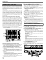
DJ MIXER
DJM-1000
Operating Instructions
Thank you for buying this Pioneer product.
Please read through these operating instructions so you will know how to operate your model properly. After you have finished
reading the instructions, put them away in a safe place for future reference.
In some countries or regions, the shape of the power plug and power outlet may sometimes differ from that shown in the explanatory
K015 En
drawings. However the method of connecting and operating the unit is the same.
WARNING
IMPORTANT
This equipment is not waterproof. To prevent a fire
or shock hazard, do not place any container filed
with liquid near this equipment (such as a vase or
flower pot) or expose it to dripping, splashing, rain
D3-4-2-1-3_A_En
or moisture.
CAUTION
RISK OF ELECTRIC SHOCK
DO NOT OPEN
The lightning flash with arrowhead symbol,
within an equilateral triangle, is intended to
alert the user to the presence of uninsulated
"dangerous voltage" within the product's
enclosure that may be of sufficient
magnitude to constitute a risk of electric
shock to persons.
READ INSTRUCTIONS — All the safety and
operating instructions should be read before the
product is operated.
RETAIN INSTRUCTIONS — The safety and
operating instructions should be retained for
future reference.
HEED WARNINGS — All warnings on the product
and in the operating instructions should be
adhered to.
FOLLOW INSTRUCTIONS — All operating and use
instructions should be followed.
CLEANING — The product should be cleaned only
with a polishing cloth or a soft dry cloth. Never
clean with furniture wax, benzine, insecticides
or other volatile liquids since they may corrode
the cabinet.
ATTACHMENTS — Do not use attachments not
recommended by the product manufacturer as
they may cause hazards.
WATER AND MOISTURE — Do not use this
product near water — for example, near a
bathtub, wash bowl, kitchen sink, or laundry
tub; in a wet basement; or near a swimming
pool; and the like.
ACCESSORIES — Do not place this product on an
unstable cart, stand, tripod, bracket, or table.
The product may fall, causing serious injury to a
child or adult, and serious damage to the
product. Use only with a cart, stand, tripod,
bracket, or table recommended by the
manufacturer, or sold with the product. Any
mounting of the product should follow the
manufacturer’s instructions, and should use a
mounting accessory recommended by the
manufacturer.
CART — A product and cart combination should be
moved with care. Quick stops, excessive force,
and uneven surfaces may cause the product
and cart combination to overturn.
VENTILATION — Slots and openings in the cabinet
are provided for ventilation and to ensure
reliable operation of the product and to protect
it from overheating, and these openings must
not be blocked or covered. The openings should
never be blocked by placing the product on a
bed, sofa, rug, or other similar surface. This
product should not be placed in a built-in
installation such as a bookcase or rack unless
proper ventilation is provided or the
manufacturer’s instructions have been adhered
to.
POWER SOURCES — This product should be
operated only from the type of power source
indicated on the marking label. If you are not
sure of the type of power supply to your home,
consult your product dealer or local power
company.
LOCATION – The appliance should be installed in a
stable location.
NONUSE PERIODS – The power cord of the
appliance should be unplugged from the outlet
when left un-used for a long period of time.
CAUTION:
TO PREVENT THE RISK OF ELECTRIC
SHOCK, DO NOT REMOVE COVER (OR
BACK). NO USER-SERVICEABLE PARTS
INSIDE. REFER SERVICING TO QUALIFIED
SERVICE PERSONNEL.
The exclamation point within an equilateral
triangle is intended to alert the user to the
presence of important operating and
maintenance (servicing) instructions in the
literature accompanying the appliance.
D3-4-2-1-1_En-A
GROUNDING OR POLARIZATION
• If this product is equipped with a polarized
alternating current line plug (a plug having one
blade wider than the other), it will fit into the
outlet only one way. This is a safety feature. If
you are unable to insert the plug fully into the
outlet, try reversing the plug. If the plug should
still fail to fit, contact your electrician to replace
your obsolete outlet. Do not defeat the safety
purpose of the polarized plug.
• If this product is equipped with a three-wire
grounding type plug, a plug having a third
(grounding) pin, it will only fit into a grounding
type power outlet. This is a safety feature. If you
are unable to insert the plug into the outlet,
contact your electrician to replace your obsolete
outlet. Do not defeat the safety purpose of the
grounding type plug.
POWER-CORD PROTECTION — Power-supply
cords should be routed so that they are not likely
to be walked on or pinched by items placed
upon or against them, paying particular
attention to cords at plugs, convenience
receptacles, and the point where they exit from
the product.
OUTDOOR ANTENNA GROUNDING — If an
outside antenna or cable system is connected to
the product, be sure the antenna or cable
system is grounded so as to provide some
protection against voltage surges and built-up
static charges. Article 810 of the National
Electrical Code, ANSI/NFPA 70, provides
information with regard to proper grounding of
the mast and supporting structure, grounding of
the lead-in wire to an antenna discharge unit,
size of grounding conductors, location of
antenna-discharge unit, connection to
grounding electrodes, and requirements for the
grounding electrode. See Figure A.
LIGHTNING — For added protection for this
product during a lightning storm, or when it is
left unattended and unused for long periods of
time, unplug it from the wall outlet and
disconnect the antenna or cable system. This
will prevent damage to the product due to
lightning and power-line surges.
POWER LINES — An outside antenna system
should not be located in the vicinity of overhead
power lines or other electric light or power
circuits, or where it can fall into such power
lines or circuits. When installing an outside
antenna system, extreme care should be taken
to keep from touching such power lines or
circuits as contact with them might be fatal.
OVERLOADING — Do not overload wall outlets,
extension cords, or integral convenience
receptacles as this can result in a risk of fire or
electric shock.
OBJECT AND LIQUID ENTRY — Never push
objects of any kind into this product through
openings as they may touch dangerous voltage
points or short-out parts that could result in a
fire or electric shock. Never spill liquid of any
kind on the product.
SERVICING — Do not attempt to service this
product yourself as opening or removing covers
may expose you to dangerous voltage or other
hazards. Refer all servicing to qualified service
personnel.
DAMAGE REQUIRING SERVICE — Unplug this
product from the wall outlet and refer servicing
to qualified service personnel under the
following conditions:
• When the power-supply cord or plug is
damaged.
• If liquid has been spilled, or objects have fallen
into the product.
• If the product has been exposed to rain or water.
• If the product does not operate normally by
following the operating instructions. Adjust only
those controls that are covered by the operating
instructions as an improper adjustment of other
controls may result in damage and will often
require extensive work by a qualified technician
to restore the product to its normal operation.
• If the product has been dropped or damaged in
any way.
• When the product exhibits a distinct change in
performance — this indicates a need for service.
REPLACEMENT PARTS — When replacement parts
are required, be sure the service technician has
used replacement parts specified by the
manufacturer or have the same characteristics
as the original part. Unauthorized substitutions
may result in fire, electric shock, or other
hazards.
SAFETY CHECK — Upon completion of any service
or repairs to this product, ask the service
technician to perform safety checks to
determine that the product is in proper
operating condition.
WALL OR CEILING MOUNTING — The product
should not be mounted to a wall or ceiling.
HEAT — The product should be situated away from
heat sources such as radiators, heat registers,
stoves, or other products (including amplifiers)
that produce heat.
IMPORTANT NOTICE – THE SERIAL NUMBER FOR
THIS EQUIPMENT IS LOCATED IN THE REAR.
PLEASE WRITE THIS SERIAL NUMBER ON YOUR
ENCLOSED WARRANTY CARD AND KEEP IN A
SECURE AREA. THIS IS FOR YOUR SECURITY.
D1-4-2-6-1_En
Information to User
Alteration or modifications carried out without
appropriate authorization may invalidate the user’s
right to operate the equipment.
D8-10-2_En
CAUTION: This product satisfies FCC regulations
when shielded cables and connectors are used to
connect the unit to other equipment. To prevent
electromagnetic interference with electric appliances
such as radios and televisions, use shielded cables
D8-10-3a_En
and connectors for connections.
This Class B digital apparatus complies with
Canadian ICES-003.
Cet appareil numérique de la Classe B est conforme
à la norme NMB-003 du Canada.
D8-10-1-3_EF
CAUTION
– PREVENT ELECTRIC SHOCK DO
NOT USE THIS (POLARIZED) PLUG
WITH AN EXTENSION CORD.
RECEPTACLE OR OTHER OUTLET
UNLESS THE BLADES CAN BE
FULLY INSERTED TO PREVENT
BLADE EXPOSURE.
ATTENTION – POUR PREVENIR LES CHOCS
ELECTRIQUES NE PAS UTILISER
CETTE FICHE POLARISEE AVEC UN
PROLONGATEUR UNE PRISE DE
COURANT OU UNE AUTRE SORTIE
DE COURANT, SAUF SI LES LAMES
PEUVENT ETRE INSEREES A FOND
SANS EN LAISSER AUCUNE PARTIE
D2-4-4-1_EF
A DECOUVVERT.
WARNING: Handling the cord on this product or
cords associated with accessories sold with the
product will expose you to lead, a chemical known to
the State of California and other governmental
entities to cause cancer and birth defects or other
reproductive harm.
Wash hands after handling
D36-P4_En
ANTENNA
LEAD IN
WIRE
GROUND
CLAMP
ANTENNA
DISCHARGE UNIT
(NEC SECTION 810-20)
ELECTRIC
SERVICE
EQUIPMENT
GROUNDING CONDUCTORS
(NEC SECTION 810-21)
GROUND CLAMPS
Fig. A
POWER SERVICE GROUNDING
ELECTRODE SYSTEM
(NEC ART 250, PART H)
NEC — NATIONAL ELECTRICAL CODE
D1-4-2-2_En
NOTE: This equipment has been tested and found to comply with the limits for a Class B digital device, pursuant to
Part 15 of the FCC Rules. These limits are designed to provide reasonable protection against harmful interference in
a residential installation. This equipment generates, uses, and can radiate radio frequency energy and, if not
installed and used in accordance with the instructions, may cause harmful interference to radio communications.
However, there is no guarantee that interference will not occur in a particular installation. If this equipment does
cause harmful interference to radio or television reception, which can be determined by turning the equipment off
and on, the user is encouraged to try to correct the interference by one or more of the following measures:
–
–
–
–
2
Reorient or relocate the receiving antenna.
Increase the separation between the equipment and receiver.
Connect the equipment into an outlet on a circuit different from that to which the receiver is connected.
D8-10-1-2_En
Consult the dealer or an experienced radio/TV technician for help.
POWER-CORD CAUTION
Handle the power cord by the plug. Do not pull out the
plug by tugging the cord and never touch the power
cord when your hands are wet as this could cause a
short circuit or electric shock. Do not place the unit, a
piece of furniture, etc., on the power cord, or pinch the
cord. Never make a knot in the cord or tie it with other
cords. The power cords should be routed such that they
are not likely to be stepped on. A damaged power cord
can cause a fire or give you an electrical shock. Check
the power cord once in a while. When you find it
damaged, ask your nearest PIONEER authorized
service center or your dealer for a replacement. S002_En
FEATURES
1 High sound quality design
Analog signals are transmitted via the shortest path and converted
to digital signals by a 96 kHz sampling, 24 bit, high-quality A/D
converter, thus passing the signals to the digital mixing stage
under optimum conditions.
Through the use of a 32 bit DSP, mixing is achieved with zero
sound quality degradation, and together with simultaneous ideal
filtering, optimum sound is produced for professional DJs
working in clubs.
To get the most from these features, a great deal of care has been
paid to perfecting the sound quality, including a high-rigidity
chassis to cut down unnecessary vibrations that might affect the
sound, together with a high-performance power section using an
R-core transformer that supports bass quality, thus creating clear
and powerful sound ideal for club performances.
2 3 band isolator
Built-in 3-band isolator capable of producing level control
+6 dB to –∞ on each bandwidth.
The sharp operation feel allows the realization of a wide variety of
DJ performances.
3 2-system, 3-type SEND/RETURN
A 2-system, 3-type SEND/RETURN (PRE INSERT/POST INSERT/
AUX) is provided to allow multiple connection variations with
other external devices, such as effectors and samplers, thus
widening the range of DJ play potential.
4 Fader curve adjust
The fader curve adjust allows adjustment not only the cross fader
curve (as on former models), but also of channel fader curve.
Both faders’ functions can be adjusted within 17 steps, so that DJs
can customize the settings to their own preferred settings.
5 Digital IN/OUT
Using digital input connectors provided for each of the sampling
rates (44.1/48/96 kHz), a system can be built in which no sound
quality degradation occurs when connecting to external digital
devices.
A DIGITAL OUT connector with 24 bit/96 kHz sampling rate is
provided, facilitating recording at studios and other situations
demanding high sound quality.
Supports only linear PCM.
CONTENTS
FEATURES ................................................................... 3
CONFIRM ACCESSORIES ........................................... 3
CAUTIONS REGARDING HANDLING ........................ 4
BEFORE USING
CONNECTIONS ............................................................
CONNECTION PANEL ...........................................
POWER CORD CONNECTION ...............................
CONNECTING TO THE INPUT CONNECTORS ...
CONNECTING TO THE EFFECTOR AND
OUTPUT CONNECTORS .......................................
MIDI CONNECTORS ..............................................
CONNECTING MICROPHONES, HEADPHONES ...
DIGITAL LINK CONNECTIONS .............................
PART NAMES AND FUNCTIONS ...............................
5
5
6
6
7
7
8
8
9
OPERATIONS
OPERATIONS .............................................................
BASIC OPERATIONS ...........................................
FADER CURVE ADJUSTMENTS .........................
FADER START FUNCTION ..................................
USING EXTERNAL EFFECTORS .........................
DIGITAL LINK FUNCTION ...................................
13
13
13
14
14
15
OTHER
TROUBLESHOOTING ................................................ 16
SPECIFICATIONS ....................................................... 17
BLOCK DIAGRAM ...................................................... 18
CONFIRM ACCESSORIES
Operating Instructions ........................................................... 1
Power cord ............................................................................. 1
Warranty ................................................................................. 1
6 MIDI OUT
MIDI signals can be output to allow MIDI control of external
devices.
7 Digital link function
Multiple functions can be performed by using digital link cables to
connect other PIONEER DJ CD players, DJ effectors and AV
mixers.
8 Other features
÷ By using a control cable to connect the unit to a PIONEER DJuse CD player, playback can be started on the CD player in
automatic linkage to operation of the fader (“fader start play”).
÷ Built-in “3-band equalizer” enabling level control within range
+6 dB to –26 dB at each bandwidth.
÷ Features “2-band booth EQ” for control of booth monitor
response, thus facilitating booth monitoring by the DJ.
÷ Built-in “cross fader assign” function, enabling more flexible
assigning of each channel’s input to the cross fader.
÷ Built-in “TALK OVER function” automatically lowers track
volume during MIC-input.
3
CAUTIONS REGARDING HANDLING
Location
Install the unit in a well-ventilated location where it will not
be exposed to high temperatures or humidity.
÷ Do not install the unit in a location which is exposed to
direct rays of the sun, or near stoves or radiators. Excessive
heat can adversely affect the cabinet and internal
components. Installation of the unit in a damp or dusty
environment may also result in a malfunction or accident.
(Avoid installation near cookers etc., where the unit may be
exposed to oily smoke, steam or heat.)
÷ When the unit is used inside a carrying case or DJ booth,
separate it from the walls or other equipment to improve
heat radiation.
Installing the DJM-1000 in an EIA rack
The screw holes on the front panel of the DJM-1000 are
designed for use in attaching the unit to a 19-inch EIA rack.
÷ Attach the unit to the rack using screws of the appropriate
size (screws not provided with the unit).
÷ When installing the unit in a rack, take care to avoid
pinching your fingers.
Note
÷ Never place this unit directly above a power amplifier, as
the heat given off by the amplifier might result in damage
to the unit. Placing the unit directly above a power
amplifier might also result in ham radio signals being
picked up or in other types of interference.
÷ Allow at least 1U (43.7 mm) space between this component
and the one mounted above it, so as to assure that the
cords connected to this unit’s input/output connectors and
terminals do not touch the component above.
÷ Always be sure to remove the unit from its rack before
shipping.
÷ When moving the unit while still installed in its rack,
exercise caution to avoid subjecting the unit to shocks or
vibration.
4
Condensation
When this unit is brought into a warm room from previously
cold surroundings or when the room temperature rises
sharply, condensation may form inside, and the unit may not
be able to attain its full performance. In cases like this, allow
the unit to stand for about an hour or raise the room
temperature gradually.
Cleaning the Unit
÷ Use a polishing cloth to wipe off dust and dirt.
÷ When the surfaces are very dirty, wipe with a soft cloth
dipped in some neutral cleanser diluted five or six times
with water and wrung out well, then wipe again with a dry
cloth. Do not use furniture wax or cleaners.
÷ Never use thinners, benzene, insecticide sprays or other
chemicals on or near this unit, since these will corrode the
surfaces.
BEFORE USING (CONNECTIONS)
CONNECTIONS
CONNECTION PANEL
1
2
3
4
5
6
7
8
9
OUTPUT
3
2
HOT
OFF
INPUT
SIGNAL GND.
COLD MASTER ATT.
0dB
1
GND –3dB
6
–6dB
–12dB
POWER
10
MASTER 2
PHONO CD / LINE
SIGNAL GND.
5
PHONO CD / LINE
4
PHONO CD / LINE
SIGNAL GND.
3
PHONO CD / LINE
2
PHONO CD / LINE
1
2
SEND
1
PHONO CD / LINE
L
(MONO)
REC
MIDI OUT
ON
L
L
L
L
L
L
R
R
R
R
R
R
L
R
L
R
MASTER 1
L
BOOTH
(TRS)
R
SUBMIC
L
L
L
L
(MONO)
(MONO)
(MONO)
(MONO)
LINE
LINE
LINE
LINE
L
(MONO)
VISUAL
SUBMIC
R
R
R
R
R
R
2 RETURN 1
AC IN
DIGITAL OUT
CONTROL
DIGITAL
CONTROL
DIGITAL
CONTROL
DIGITAL
CONTROL
DIGITAL
CONTROL SOUND 2
CONTROL
EFX 2
SOUND 1
EFX 1
fs(Hz)
48k
22
21
96k
20
19 18
17
16
1. POWER switch
2. MASTER output connector 1 (MASTER 1)
XLR type balanced output (male connector).
3. MASTER output connector 2 (MASTER 2)
RCA type unbalanced output.
4. MASTER output attenuator dial (MASTER ATT.)
Attenuates the output level of MASTER 1 and MASTER 2 output.
The level of attenuation can be chosen from 0 dB, –3 dB, –6 dB,
–12 dB.
5. Recording output connectors (REC)
RCA type output connector for recording.
6. PHONO input connectors
RCA type phono level (for MM cartridge) input connectors.
Do not use for input of line level signals.
7. Signal grounding terminal (SIGNAL GND)
Use to connect grounding wire from analog player.
Not a terminal for safety grounding.
8. CD/LINE input connectors
15
14
13
12
11
13. EFX link input/output connectors (EFX 1, 2)
When a digital-link cable is used to connect the unit to a PIONEER
DJ effector supporting digital linkage (EFX-1000), SEND/RETURN
connections are performed at once digitally, and functions such as
fader effect are also enabled.
14. LINE input connectors
Ø6.3 mm phone type line level connectors.
When only the L channel is connected, the input to the L channel
will also be input into the R channel.
15. CDJ link input connectors (SOUND 1, 2)
When a digital-link cable is used to connect the unit to a PIONEER
DJ CD player supporting digital linkage, the digital audio
connections and control cable connections are performed at once,
and functions such as BPM synchro are also enabled.
16. DIGITAL input connectors
RCA type digital coaxial input connectors.
Connect to digital coaxial output connectors of DJ CD player, etc.
17. SUBMIC input connectors
RCA type line level input connectors.
Use to connect DJ CD players and/or line level output devices.
Ø6.3 mm phone type microphone input connectors.
Utilizes the DJM-1000’s channels 5 and 6 as microphone input
channels.
9. SEND output connectors (SEND 1, 2)
18. CONTROL connectors
Ø6.3 mm phone type output connectors.
Use to connects input connectors from external effectors, etc.
When only the L channel is connected, a monaural signal of L+R is
output.
Ø3.5 mm mini phone-type input connector for connecting control
cable to DJ CD player.
Allows use of the DJM-1000’s fader function to control start/stop
of a connected DJ CD player.
10. MIDI output connector (MIDI OUT)
19. BOOTH monitor output connectors
DIN type output connector.
Connects with other MIDI devices (P.7).
Ø 6.3 mm phone type output connectors for booth monitor.
Changes the volume with the BOOTH MONITOR dial (LEVEL),
unaffected to the MASTER fader (since output is TRS, both
balanced and unbalanced outputs are supported).
11. VISUAL link connector
When a digital link cable is used to connect the unit to a PIONEER
video mixer (switcher) supporting digital-linkage, the video
mixer’s cross fader can be controlled using the cross fader of the
DJM-1000.
20. Digital output connector (DIGITAL OUT)
RCA type digital coaxial output connector.
Digital master output.
12. RETURN connectors (RETURN 1, 2)
21. Sampling frequency selector switch (48k/96k)
Ø6.3 mm phone type output connectors.
Connect to input connectors of external effectors, etc.
When only the L channel is connected, the input in the L channel
will be input into the R channel.
Chooses the sampling frequency of the digital output (96 kHz or
48 kHz).
22. Power inlet connector (AC IN)
Connect to AC outlet plug with the provided power cord.
5
BEFORE USING (CONNECTIONS)
Before making or changing connections, switch off the power and disconnect the power cord from the AC outlet.
POWER CORD CONNECTION
Connect the power cord last.
÷ When all other connections are completed, connect the supplied power cord to the AC inlet located on the rear panel of this unit, and
connect the power plug to an AC outlet or auxiliary power socket on an amplifier.
÷ Be sure to use only the supplied power cord.
CONNECTING TO THE INPUT CONNECTORS
PIONEER DJ CD players
Other line level output devices
Connect the DJ CD player’s audio output connectors to one of the
sets of CD/LINE input connectors on the DJM-1000, and connect
the control cable to the corresponding channel’s CONTROL
connector. Switch the input selector switch of the connected
channel to [CD/LINE].
When using digital connections, connect the digital coaxial output
connector to one of the DIGITAL input connectors of the DJM1000, and switch the input selector switch of the connected
channel to [DIGITAL] (no digital input connectors are provided for
channel 1 and channel 2).
When connecting cassette decks or CD players, connect the audio
output connectors to one of the CD/LINE input connectors of the
DJM-1000, and switch the input selector switch of the connected
channel to [CD/LINE].
When the connection plug is a Ø6.3 mm phone plug, connect to
one of the LINE input connectors of the DJM-1000, and switch the
input selector switch of the connected channel to [LINE] (no LINE
input connectors are provided for channel 5 and channel 6). When
only the L channel is connected, the input in the L channel will be
input to the R channel as well.
Analog turntables
Digital output devices
Connect the audio output cables of the analog turntable to one set
of PHONO input connectors on the DJM-1000, and switch the input
selector switch of the connected channel to [PHONO]. The PHONO
input of the DJM-1000 supports MM cartridges.
The ground cable of an analog turntable is connected to one of the
SIGNAL GND terminals.
When using digital connections to devices such as CD players,
connect the device’s digital coaxial output connector to one of the
DIGITAL input connectors of the DJM-1000, and switch the input
selector switch of the connected channel to [DIGITAL] (no DIGITAL
input connectors are provided for channel 1 and channel 2).
DJ CD player
DJ CD player
Analog turntable
R
L
R
L
R
OUTPUT
3
2
HOT
OFF
6
–6dB
–12dB
MASTER 2
L
L
R
INPUT
SIGNAL GND.
COLD MASTER ATT.
0dB
1
GND –3dB
POWER
Analog turntable
PHONO CD / LINE
SIGNAL GND.
5
4
PHONO CD / LINE
PHONO CD / LINE
SIGNAL GND.
3
2
PHONO CD / LINE
1
PHONO CD / LINE
2
SEND
1
PHONO CD / LINE
L
(MONO)
REC
L
L
L
L
L
L
R
R
R
R
R
R
L
R
L
R
MASTER 1
L
L
L
L
L
(MONO)
(MONO)
(MONO)
(MONO)
LINE
LINE
LINE
LINE
R
R
R
R
BOOTH
(TRS)
R
SUBMIC
L
(MONO)
VISUAL
SUBMIC
R
R
2 RETURN 1
AC IN
DIGITAL OUT
CONTROL
DIGITAL
CONTROL
DIGITAL
CONTROL
DIGITAL
CONTROL
DIGITAL
CONTROL SOUND 2
CONTROL
SOUND 1
EFX 2
fs(Hz)
48k
96k
L
CD player, etc.
6
MIDI OUT
ON
R
R
L
Cassette deck, etc.
EFX 1
BEFORE USING (CONNECTIONS)
CONNECTING TO THE EFFECTOR AND OUTPUT CONNECTORS
Master output
External effector
There is an XLR plug correspondent balanced output MASTER 1,
and a RCA plug correspondent unbalanced output MASTER 2. Set
the output level using the MASTER ATT. dial to match the input
sensitivity of the connected power amplifier.
Use a cable with Ø6.3 mm phone plugs to connect the DJ mixer’s
SEND connectors to the input connectors of an external effector.
When using a monaural input effector, connect only the L channel
output. In this way, the mixed L/R audio signal will be sent to the
effector.
In the same way, use a cable with Ø6.3 mm phone plugs to
connect the DJ mixer’s RETURN connectors to the output
connectors of the external effector.
When the effector has only monaural output, connect the L
channel input only. In this way, the signal from the effector will be
input to both L/R channels.
Booth monitor output
Unbalanced output supporting Ø6.3 mm phone plug. Volume can
be adjusted with the BOOTH MONITOR dial (LEVEL), regardless of
the setting of the MASTER fader.
Recording output
Output connectors for recording, supports RCA plug.
Digital output
Coaxial digital output connector, supports RCA plug. Sampling
frequency can be selected (96 kHz/48 kHz) in accordance with
connected device.
Power amplifier
(RCA plug input connector)
Cassette deck, etc.
(analog input recording device)
External effector (2)
MASTER
ATT.
R
L
L
R
OUTPUT
3
2
HOT
6
–6dB
–12dB
POWER
OFF
INPUT
SIGNAL GND.
COLD MASTER ATT.
0dB
1
GND –3dB
MASTER 2
PHONO CD / LINE
SIGNAL GND.
5
PHONO CD / LINE
4
PHONO CD / LINE
SIGNAL GND.
3
2
PHONO CD / LINE
PHONO CD / LINE
1
2
SEND
1
PHONO CD / LINE
L
(MONO)
REC
MIDI OUT
ON
L
L
L
L
L
L
R
R
R
R
R
R
L
R
L
R
MASTER 1
L
BOOTH
(TRS)
R
SUBMIC
L
L
L
L
(MONO)
(MONO)
(MONO)
(MONO)
LINE
LINE
LINE
LINE
L
(MONO)
VISUAL
SUBMIC
R
R
R
R
R
R
2 RETURN 1
AC IN
DIGITAL OUT
CONTROL
DIGITAL
CONTROL
DIGITAL
CONTROL
DIGITAL
CONTROL
DIGITAL
CONTROL SOUND 2
CONTROL
SOUND 1
EFX 2
EFX 1
fs(Hz)
48k
96k
48k/96k
External effector (1)
Power amplifier
(XLR plug input
connector)
Digital input AV amplifier
(Digital input
recording device)
Power amplifier
(For booth monitor)
MIDI CONNECTORS
MIDI (Musical Instrument Digital Interface) is a unified standard for transmitting data between electrical musical instruments and
computers.
Data can be transmitted between devices with MIDI connectors using a MIDI cable.
The DJM-1000 can send operating data to external MIDI devices using the MIDI protocol.
DJM-1000 control
MIDI control code
MIDI control name
MIDI Channel
Cross fader operation
CC11
Expression
1
* 0-127 MIDI data is output by operating the cross fader.
* When using the visual link function, MIDI data is not output.
7
BEFORE USING (CONNECTIONS)
CONNECTING MICROPHONES, HEADPHONES
Headphones
Sub microphone
Headphones with Ø6.3 mm stereo phone plugs can be connected
to the PHONES plug in the operation panel (top panel).
A Ø6.3 mm phone plug microphone can be connected to the
SUBMIC input connectors on channel 5 and channel 6 of the DJM1000.
Switch the input selector switch of the connected channel to
[SUBMIC].
Main microphone
A microphone with either a Ø6.3 mm phone plug or XLR plug can
be connected to the MIC plug in the operation panel (top panel).
Headphones
Sub microphone
Main microphone
HEADPHONES
LINK
MONO
SPLIT
MIC
VISUAL
STEREO
V
MIXING
SOUND 1
S1
SOUND 2
CUE
MIC LEVEL
S2
MASTER
LEVEL
EFX 1
E1
EFX 2
0
E2
0
HI
FADER START
CH-1
PHONES
1
–6
CH-2
+6
LOW
2
EQ
CH-3
3
CH-4
OUTPUT
3
2
HOT
POWER
OFF
6
–6dB
–12dB
PHONO CD / LINE
MASTER 2
SIGNAL GND.
5
PHONO CD / LINE
4
PHONO CD / LINE
–6
+6
4
INPUT
SIGNAL GND.
COLD MASTER ATT.
0dB
1
GND –3dB
3
PHONO CD / LINE
2
PHONO CD / LINE
MIC
CH-5
SIGNAL GND.
1
2
SEND
15
CH-6
PHONO CD / LINE
6
REC
L
(MONO)
OFF ON TALK
MIDI OUT OVER
ON
L
L
L
L
L
L
R
R
R
R
R
R
L
R
L
R
MASTER 1
L
BOOTH
(TRS)
R
SUBMIC
L
L
L
L
(MONO)
(MONO)
(MONO)
(MONO)
LINE
LINE
LINE
LINE
R
R
R
R
L
(MONO)
VISUAL
SUBMIC
R
R
2 RETURN 1
AC IN
DIGITAL OUT
CONTROL
DIGITAL
CONTROL
DIGITAL
CONTROL
DIGITAL
CONTROL
DIGITAL
CONTROL SOUND 2
CONTROL
SOUND 1
EFX 2
EFX 1
fs(Hz)
48k
96k
DIGITAL LINK CONNECTIONS
(Includes connections to future components supporting digital link.)
AV mixer supporting
digital link
SIGNAL GND.
2
PHONO CD / LINE
1
2
SEND
VISUAL link connector
1
PHONO CD / LINE
L
(MONO)
L
L
R
R
MIDI OUT
R
L
L
(MONO)
(MONO)
LINE
LINE
L
(MONO)
VISUAL
Effector supporting
digital link (EFX-1000)
R
R
R
CONTROL
SOUND 1
EFX 2
When a digital link cable is used to connect the
unit to a PIONEER video mixer (switcher)
supporting digital linkage, the cross fader
function of the video mixer can be operated by
using the cross fader of the DJM-1000. (P.15)
EFX link input/output connectors
(EFX 1, 2)
2 RETURN 1
CONTROL SOUND 2
By connecting a single dedicated cable
(digital link cable), exchange of audio signals
and control signals can be performed digitally
(The connection of audio cables or control
cables is unneeded).
EFX 1
Effector supporting
digital link (EFX-1000)
When a digital link cable is used to connect the
unit to a PIONEER DJ effector supporting digital
linkage (EFX-1000), SEND/RETURN connections
are performed at once digitally, thus allowing
the use of fader effect functions and BPM sync
functions when sound link connections are
used. (P.15)
CDJ link input connectors
(SOUND 1, 2)
DJ CD player
supporting digital link
8
DJ CD player
supporting digital link
When a digital link cable is used to connect the
unit to a PIONEER DJ CD player supporting digital
linkage, digital audio connections and control
cable functions are performed at once, and
functions such as BPM synchro are also enabled.
Switch the input selector switch of the channel 1
and 2 to [SOUND 1] and [SOUND 2]. (P.15)
BEFORE USING (PART NAMES AND FUNCTIONS)
PART NAMES AND FUNCTIONS
Operation Panel
1
7
LINK
9
10
11
12 28
29
MIC
CD/LINE
LINE
PHONO
SOUND 1
VISUAL
44
8
V
CD/LINE
LINE
PHONO
SOUND 2
CD/LINE
LINE
PHONO
DIGITAL
CD/LINE
LINE
PHONO
DIGITAL
CD/LINE
SUBMIC
PHONO
DIGITAL
HI
CD/LINE
SUBMIC
PHONO
DIGITAL
ISOLATOR
ON
30
SOUND 1
S1
45
2
SOUND 2
MIC LEVEL
S2
13
TRIM
OVER
13
TRIM
OVER
13
TRIM
OVER
13
TRIM
OVER
13
TRIM
OVER
13
TRIM
OVER
MASTER LEVEL
EFX 1
46
10
EFX 2
FADER START
3
10
7
0
E2
HI
+9
HI
4
10
7
14
+9
HI
4
10
7
14
+9
HI
4
10
7
14
+9
HI
4
10
7
14
7
14
+9
HI
4
+9
HI
4
14
10
10
7
7
4
4
2
2
2
2
2
2
2
2
CH-1
1
1
1
1
1
1
1
1
1
0
0
0
0
0
0
0
0
1
1
2
2
3
3
5
5
–6
CH-2
+6
LOW
4
2
EQ
1
CH-3
3
47
+6
MID
OVER OVER
E1
–26
+6
MID
2
15
3
EQ
1
5
CH-4
–6
4
7
15
3
EQ
5
16
+6
MID
2
15
3
EQ
1
5
16
+6
MID
2
15
3
EQ
1
5
16
+6
MID
2
15
3
EQ
1
5
16
+6
MID
2
15
3
EQ
5
16
7
7
10
10
15
15
24
24
24
24
24
24
24
24
+6
LOW
–26
+6
LOW
10
–26
+6
LOW
10
7
16
15
–26
10
7
–26
15
+6
LOW
7
–26
15
–26
10
7
–26
15
+6
LOW
7
–26
15
–26
10
OFF ON TALK
OVER
6
MID
2
1
–26
+6
LOW
10
+6
LOW
32
+6
MIC
5
CH-6
+6
15
+6
5
CH-5
–26
31
6
dB
–26
+6
dB
17 18
1 — SEND/RETURN — 2
–26
+6
dB
17 18
–26
dB
+6
17 18
–26
+6
dB
17 18
–26
dB
+6
17 18
–26
L
+6
17 18
dB
BOOTH MONITOR
HI
33
R
MASTER
–6
+6
LOW
18
CUE
CUE
PRE POST AUX
INSERT
PRE POST AUX
INSERT
CUE
40
CUE
CUE
CUE
CUE
CUE
18
2
3
5
6
MIC
3
2
4
1
5
6
MIC
MASTER
MASTER
41
LEVEL
MIN
42
4
1
LEVEL
MAX
ON
MIN
MAX
18
–6
+6
LEVEL
10
10
10
10
10
10
10
9
9
9
9
9
9
9
8
8
8
8
8
8
8
7
7
7
7
7
7
7
6
6
6
6
6
6
6
5
5
5
5
5
5
5
4
4
4
4
4
4
4
3
3
3
3
3
3
3
2
2
2
2
2
2
2
1
1
1
1
1
1
1
0
0
0
0
0
0
0
ON
43
34
CUE
25
21
25
21
25
21
25
21
21
25
21
35
0
HEADPHONES
MONO
SPLIT
STEREO
MIXING
25
26
CUE
36
37
MASTER
LEVEL
38
CURVE ADJUST
CH FADER
CROSS FADER
BALANCE
0
A THRU B
A THRU B
A THRU B
A THRU B
A THRU B
A THRU B
CROSS FADER ASSIGN
L
R
39
PROFESSIONAL 6 CHANNEL MIXER
19
20
22
23
Main microphone input control section
1. Main MIC input connector
Connect to microphones with XLR type or phone type
connector.
2. MIC LEVEL adjustment dial
Adjusts the volume of the main microphone.
(Adjustable range: –∞ to 0 dB)
3. Microphone equalizer high-range sound adjust
dial (EQ HI)
Adjusts the high-range sound of the main microphone.
(Adjustable range: –6 dB to +6 dB)
4. Mic equalizer low-range sound adjust dial
(EQ LOW)
Adjusts the low-range sound of the main microphone.
(Adjustable range: –6 dB to +6 dB)
5. Microphone function indicator
Lights when MIC selector switch is set to [ON]. Flashes
when selector switch is set to [TALK OVER].
24
PHONES
27
6. MIC function selector switch
OFF:
Main microphone audio is not output.
ON:
Main microphone audio is output.
TALK OVER:
Main microphone audio is output. When a sound is input to
the main microphone input, the TALK OVER function
operates and the output of all sound except for the main
microphone audio is attenuated 20 dB.
Channel input control section
7. Channel 1 input selector switch
SOUND 1:
Dedicated input for DJ CD players supporting digital link
(mini DIN connector).
LINE:
Phone type connector (When a monaural signal is
connected to only the L channel, the signal is input to both
L and R channels).
CD/LINE:
RCA type connector with line level input.
PHONO:
RCA type connector with phono level input.
9
BEFORE USING (PART NAMES AND FUNCTIONS)
8. Channel 2 input selector switch
SOUND 2:
Dedicated input for DJ CD players supporting digital link
(mini DIN connector).
LINE:
Phone type connector (when a monaural signal is
connected to only the L channel, the signal is input to both
L and R channels).
CD/LINE:
RCA type connector with line level input.
PHONO:
RCA type connector with phono level input.
9. Channel 3 input selector switch
DIGITAL:
RCA type connector with coaxial cable digital input.
LINE:
Phone type connector (when a monaural signal is
connected to only the L channel, the signal is input to both
L and R channels).
CD/LINE:
RCA type connector with line level input.
PHONO:
RCA type connector with phono level input.
10. Channel 4 input selector switch
DIGITAL:
RCA type connector for coaxial cable digital input.
LINE:
Phone type connector (when a monaural signal is
connected to only the L channel, the signal is input to both
L and R channels).
CD/LINE:
RCA type connector with line level input.
PHONO:
RCA type connector with phono level input.
11. Channel 5 input selector switch
DIGITAL:
RCA type connector for coaxial cable digital input.
SUBMIC:
Phone type connector for sub microphone input
(monaural).
CD/LINE:
RCA type connector with line level input.
PHONO:
RCA type connector with phono level input.
12. Channel 6 input selector switch
DIGITAL:
RCA type connector for coaxial cable digital input.
SUBMIC:
Phone type connector for sub microphone input
(monaural).
CD/LINE:
RCA type connector with line level input.
PHONO:
RCA type connector with phono level input.
13. Channel 1-6 TRIM adjustment dials
Adjusts each channel’s input level.
(Adjustable range: –∞ to +9 dB, approaches 0 dB at midpoint)
10
14. Channel equalizer high-range sound adjust dials
(EQ HI)
Adjusts each channel’s high-range sound.
(Adjustable range: –26 dB to +6 dB)
15. Channel equalizer mid-range sound adjust dials
(EQ MID)
Adjusts each channel’s mid-range sound.
(Adjustable range: –26 dB to +6 dB)
16. Channel equalizer low-range sound adjust dials
(EQ LOW)
Adjusts each channel’s low-range sound.
(Adjustable range: –26 dB to +6 dB)
17. Channel level indicators
Displays each channel level. The display provides 2
seconds peak hold.
18. Headphone CUE button/indicators
The selected source to be monitored by headphones is
chosen by pressing the CUE button for RETURN 1, RETURN
2, channel 1-6, or MASTER. When multiple buttons are
pressed at once, the selected audio sounds are mixed.
When a button is pressed again, the selection is canceled.
The buttons of unselected sources light dimly, and the
buttons of the selected sources light brightly.
Fader control section
19. Curve adjust channel fader dial
(CURVE ADJUST CH FADER)
Adjusts the curve characteristics of the channel fader.
(P.13)
20. Curve adjust cross fader dial
(CURVE ADJUST CROSS FADER)
Adjusts the curve characteristics of the cross fader. (P.13)
21. CROSS FADER ASSIGN switches/indicators
Selects which side of the cross fader the output from each
channel is directed to. (When multiple channels have been
selected in the same side, the combined sum is assigned to
that side.)
A:
The channel output is directed to the A side (left side) of the
cross fader. The A indicator will light.
THRU:
The channel output is directed to the master output without
going through the cross fader. Both A and B indicators will
go out.
B:
The channel output is directed to the B side (right side) of
the cross fader. The B indicator will light.
22. Cross fader assign A indicator (A)
Lights orange when power is ON.
23. Cross fader slider
The audio directed to either the A side or B side by the
CROSS FADER ASSIGN switch for each channel is output in
accordance with the cross fader curve set by the CURVE
ADJUST dial (CROSS FADER).
BEFORE USING (PART NAMES AND FUNCTIONS)
24. Cross fader assign B indicator (B)
Lights green when power is ON.
25. Channel fader slider
Adjusts volume of each channel.
(Adjustable range: –∞ to 0 dB)
Outputs according to the channel fader curve set by the
CURVE ADJUST dial (CH FADER).
Master output control section
26. MASTER fader slider
Headphone output section
36. Headphone output selector switch
(HEADPHONES — MONO SPLIT/STEREO)
MONO SPLIT:
The audio source selected by the headphone CUE button is
output from the left channel, and the master audio is
output from the right channel (Only when MASTER is
selected with the headphone CUE button).
STEREO:
The selected audio is output in stereo.
Adjusts the volume of the master output.
(Adjustable range: –∞ to 0 dB)
The master output is the combination of the channel whose
audio has been set to [THRU] by the CROSS FADER
ASSIGN switch, together with the audio passed through
the cross fader and the audio from the main microphone
(depending on the mode, RETURN input will also be
added).
37. Headphone MIXING dial (HEADPHONES MIXING)
27. MASTER BALANCE dial
38. Headphone LEVEL adjust dial
(HEADPHONES LEVEL)
Adjusts the L/R channel balance of the master output,
booth monitor output, recording output, and digital output.
28. MASTER LEVEL indicators (L, R)
When turned clockwise (MASTER direction) the master
output audio is output (only when MASTER is selected with
the headphone CUE button); when turned counterclockwise
(CUE direction), the audio output will be a mixture of the
sound from the channel selected with the headphone CUE
button, and the sound coming from the external effector
(RETURN).
Adjusts the output volume of the headphone connector.
(Adjustable range: –∞ to 0 dB)
Displays output levels of the L channel and the R channel.
Each segment provides 2 seconds of peak hold.
39. Headphone jack (PHONES)
29. MASTER ISOLATOR button/indicator (ON)
SEND/RETURN section
40. SEND/RETURN type selector switches
Turns master isolator function ON/OFF.
The isolator function operates with respect to master
output 1, master output 2, booth monitor output, recording
output and digital output.
Turns off when OFF, and lights when ON.
30. MASTER ISOLATOR high-range sound adjust
dial (HI)
Use to adjust the high-range sound of the master output
signal.
(Adjustable range: –∞ to +6 dB)
Use to switch between the sending stage (SEND) and input
stage (RETURN) for signals when connected to an external
effector (P.14).
[Pre-Insert type]
Input
EQ
31. MASTER ISOLATOR mid-range sound adjust dial
(MID)
Used to adjust the mid-range sound of the master output
signal.
(Adjustable range: –∞ to +6 dB)
SEND
RETURN
S/R ON
32. MASTER ISOLATOR low-range sound adjust dial
(LOW)
CH
FADER
Used to adjust the low-range sound of the master output
signal.
(Adjustable range: –∞ to +6 dB)
CROSS
FADER
S/R LEVEL
MASTER
FADER
Output
MASTER
FADER
Output
[Post-Insert type]
Booth monitor control section
33. BOOTH MONITOR equalizer high-range sound
adjust dial (HI)
Used to adjust the high-range sound of the booth monitor
output signal.
(Adjustable range: –6 dB to +6 dB)
Input
EQ
CH
FADER
34. BOOTH MONITOR equalizer low-range sound
adjust dial (LOW)
Used to adjust the low-range sound of the booth monitor
output signal.
(Adjustable range: –6dB to +6 dB)
35. BOOTH MONITOR LEVEL adjust dial
Adjusts the volume of the booth monitor output.
Adjustable regardless of setting of master fader.
(Adjustable range: –∞ to 0 dB)
SEND
RETURN
S/R ON
CROSS
FADER
S/R LEVEL
11
BEFORE USING (PART NAMES AND FUNCTIONS)
46. Effector LINK buttons 1, 2 (EFX 1, 2)/Indicator
(E 1, 2)
[AUX type]
Input
When a digital link cable (mini DIN connector) is used to
connect this unit to a PIONEER DJ effector with digital link
support (EFX-1000), setting these buttons to ON enables
fader effect functions.
The indicator lights when the function is turned ON.
EQ
CH
FADER
SEND
RETURN
Fader start/stop ON/OFF section
47. Fader start button/indicators
(FADER START CH-1 to CH-6)
S/R LEVEL
S/R ON
CROSS
FADER
MASTER
FADER
Output
41. SEND channel selector switches
Use to select the send audio from MIC, channels 1-6, and
MASTER.
42. RETURN input level adjust dials (LEVEL)
Adjusts the level of the signal returned.
(Adjustable range: –∞ to +6 dB)
43. SEND/RETURN buttons/indicators (ON)
Use to switch ON/OFF the SEND/RETURN operation of the
selected type on the selected channel.
Lights when a plug is inserted to the RETURN connector, or
when a component supporting digital link is connected to
the EFX connector. If the button is pressed when lighted,
the function turns ON and the indicator flashes. When
indicator is ON, input signal to RETURN connector is
enabled. When a digital-link component is connected to the
EFX connector, the digital link component (digital signal) is
given priority.
Link function ON/OFF section
44. VISUAL LINK button/Indicator (V)
When a digital link cable (mini DIN connector) is used to
connect a PIONEER video mixer/switcher supporting digital
link, the video mixer’s cross fader can be operated using
the cross fader of the DJM-1000.
The indicator lights when the function is turned ON.
45. SOUND LINK buttons 1, 2 (SOUND 1, 2)/
indicator (S1, 2)
When this unit is connected via digital link to a PIONEER DJ
effector with digital link support (EFX-1000), and a
PIONEER DJ CD player with digital link support is also
connected via digital link cable (mini DIN connector),
setting these buttons to ON enables BPM sync functions.
The indicator lights when the function is turned ON.
12
When the CROSS FADER ASSIGN switches for each
channel are used to select [A] or [B], the cross fader start/
stop function of that channel’s DJ CD player are turned ON/
OFF.
When [THRU] is selected by the CROSS FADER ASSIGN
switch for each channel, the channel fader start/stop
function for that channel’s DJ CD player is turned ON/OFF.
The button for each channel lights up when the fader start/
stop function is turned ON, and is turned off when the fader
start/stop function is turned OFF.
OPERATIONS
OPERATIONS
[Headphones output]
BASIC OPERATIONS
1. Choose the source with the headphone CUE button
(channel 1-6, MASTER, RETURN 1, RETURN 2).
Booth monitor output
Main microphone input
÷ The chosen headphone CUE button will light brightly.
2. Use the HEADPHONES selector switch (MONO SPLIT/
STEREO) to select the format of the audio output.
1
2
7
3
4
–26
+6
5
8
6
Fader curve
Headphone output
1. Set the POWER switch located on the rear panel (connection panel) to ON.
2. Set the input selector switches for the channels used to
the devices connected to those channels.
3. Use the TRIM dial to adjust the input level.
4. Adjust the tone using the EQ dials (HI, MID, LOW).
5. Adjust the volume of the channel with the channel fader
slider.
6. When cross fading between channels, use the CROSS
FADER ASSIGN switch to choose between channel [A] and
channel [B] of the cross fader, and operate the cross fader.
÷ When not using the cross fader, choose [THRU] with the
CROSS FADER ASSIGN switches.
7. When using the isolator, switch the MASTER ISOLATOR
button ON, and adjust the level of each bandwidth with
the MASTER ISOLATOR dials (HI, MID, LOW).
÷ When [MONO SPLIT] is chosen, the audio chosen with the CUE
button will be output from the left channel, and the master
audio (enabled only when the CUE button for the MASTER is
turned ON) will be output from the right channel.
÷ When [STEREO] is chosen, the audio chosen with the CUE
button will be output in stereo.
3. When [MONO SPRIT] is chosen, use the HEADPHONES
dial (MIXING) to adjust the balance of the left channel
(chosen by the headphone CUE button), and the right
channel (master audio—supported only when the
headphone CUE button for MASTER is turned ON).
÷ When turned clockwise (MASTER direction) the master output
(only when CUE button for MASTER is turned ON) will be
output, and when turned counterclockwise (CUE direction) the
audio chosen by the CUE button will be output.
4. Adjust the volume of the headphones with the
HEADPHONES dial (LEVEL).
FADER CURVE ADJUSTMENTS
This allows adjustment of the sound volume change characteristics
corresponding to the movement of the fader operation.
7 Turn the CURVE ADJUST dial (CH FADER), and adjust the
curve characteristics of the channel fader.
÷ When turned fully to the right, raising the fader will cause
the volume to change in a nearly linear fashion (equivalent
to B-curve).
÷ When turned fully to the left, the volume curve will change
so that sound volume increases slowly until the fader is
raised almost fully.
÷ The curve of the channels 1-6 will all change at the same time.
CH FADER
10
8. Use the MASTER fader slider to adjust the overall
volume, and adjust the left and right volume balance by
using the MASTER BALANCE dial.
e
÷ The MASTER ISOLATOR button will light when switched
ON.
cu
rv
9
B-
8
7
6
5
CH FADER
4
3
2
[Main microphone input]
1
0
1. When using the main microphone, either set the MIC
selector switch to [ON] or set to [TALK OVER].
÷ When set to [TALK OVER], the output of all sound except for
the main microphone audio is attenuated 20 dB when a
sound higher than –15 dB is input to the main microphone
input.
2. Adjust the volume with the MIC LEVEL dial, and adjust
the tone with the MIC EQ dials (HI, LOW).
[Booth monitor output]
1. Adjust the volume with the BOOTH MONITOR dial
(LEVEL).
÷ The volume can be adjusted with the BOOTH MONITOR dial
(LEVEL), regardless of the setting of the MASTER fader
slider.
2. Adjust the tone using the BOOTH MONITOR dial (HI
“high-range sound”) and BOOTH MONITOR dial (LOW
“low-range sound”).
7 Turn the CURVE ADJUST dial (CROSS FADER), and adjust
the curve characteristics of the cross fader.
÷ When turned all the way to the right, the cross fader
becomes a steep rising curve in which moving the fader
from the side causes instant appearance of the sound on the
opposite side.
÷ When turned all the way to the left, the cross fader becomes
an almost linier volume change curve.
÷ Both curves of the A and B side will change at once.
CROSS FADER
A
B
B
A
CROSS FADER
A
B
13
OPERATIONS
[Starting playback with cross fader]
FADER START FUNCTION
1 Press the FADER START button for the channel (CH-1 to
CH-6) connected to the CD player you wish to control.
By using a control cable to connect the unit to an optional
PIONEER CD player, playback on the CD player can be
started using the channel fader or cross fader functions (if a
digital link connection is made, use of the control cable is
unnecessary).
The CD player’s pause function is canceled when the
mixer’s channel fader slider or cross fader slider is moved,
and the playback of the track starts automatically and
instantly. In addition, by returning the fader to it’s former
position, the CD player’s playback can be returned back to
the cue point (back cue), so that sampler-like playback can
be performed.
[Cross fader start play & back cue play]
During cue point standby on the CD player assigned to
channel A of the cross fader, moving the cross fader slider
from the right side (B side) to the left side (A side) causes
the CD player connected to channel A to start playback.
When the cross fader slider reaches the left side (A side),
the CD player assigned to channel B will back cue (return to
cue point). When the CD player assigned to channel B is in
cue point standby mode, moving the cross fader slider
from the left side (A side) to the right side (B side), causes
playback on the CD player assigned to channel B to begin.
When the cross fader slider reaches the right side (B side),
the CD player assigned to channel A will back cue.
* Back cue will occur even if the input selector switch is
not set to [CD/LINE].
÷ The button of the selected channel will light.
2 Set the CROSS FADER ASSIGN switch of the selected
channel to either [A] or [B].
÷ When assigning to channel A (left side) of the cross fader,
set to [A].
÷ When assigning to channel B (right side) of the cross fader,
set to [B].
3 Move the cross fader slider as far as it will go to the
opposite side of the channel you wish to start.
4 Set a cue point on the CD player, and set to standby at
the cue point.
÷ If a cue point has already been set, the CD player does not
have to be set to standby at the cue point.
5 Move the cross fader slider at the desired timing to start
playback.
÷ CD player will start playback.
÷ After playback has started, by moving the cross fader slider
all the way, the CD player assigned at the opposite side will
return to cue point and enter standby mode (back cue).
* The fader start function may not operate properly when
digital connections are made alone. In this event, connect
the CD player's analog connectors as well.
USING EXTERNAL EFFECTORS
Two effectors can be connected if desired.
1. Use the SEND channel selector switch to choose the
source to be sent to the effector.
÷ Select from either [MIC], channel [1]-[6], or [MASTER].
2. Use the SEND/RETURN selector switch to choose the
stage to which the effector is connected.
–26
+6
External effector
÷ When the send channel is set to [MIC], [INSERT] and [AUX]
switching only are enabled from the same point for both
[PRE] and [POST]. When send channel is set to [MASTER],
only [INSERT] is enabled.
PRE INSERT:
Equalizer output, sent from before the channel fader and
returned to same point.
POST INSERT:
Channel fader output, sent from before the cross fader
assign, and returned to the same point.
AUX:
Channel fader output, sent from before the cross fader
assign and returned to the point before the master fader,
and then added to any other output. The original sound
which has been sent will also be passed through the cross
fader assign and added.
3. Set the SEND/RETURN button to ON.
÷ The SEND/RETURN button flashes.
[Starting playback with channel fader]
1 Press the FADER START button for the channel (CH-1 to
CH-6) connected to the CD player you wish to control.
÷ The button of the selected channel will light.
2 Move the channel fader slider to the [0] position.
3 Set a cue point in the CD player, and set to standby at
cue point.
÷ If a cue point has already been set, the CD player does
not have to be set to standby at the cue point.
4 Move channel fader slider at the desired timing to start
playback.
÷ CD player will start playback.
÷ After playback has started, moving the channel fader
slider back to [0] causes the CD player to return to cue
point and enter standby mode (back cue).
* Channel fader is enabled for control only when CROSS
FADER ASSIGN switch is set to [THRU].
14
4. Adjust the RETURN volume with the RETURN dial
(LEVEL).
Position
PRE POST AUX
INSERT
Source
MIC
CH-1 — CH-6
MASTER
EQUALIZER
PRE POST AUX
INSERT
PRE POST AUX
INSERT
INSERT
PRE
POST
INSERT
CH. FADER
C. F. ASSIGN
SEND/RETURN
SEND/RETURN
ON
CROSS FADER
ON
LEVEL
LEVEL
POST INSERT
PRE INSERT
AUX
SEND
PRE
INSERT
AUX
AUX
MASTER FADER
ON
SEND/RETURN
POST
INSERT
AUX
RETURN
LEVEL
OPERATIONS
DIGITAL LINK FUNCTION
Link system diagram
DJ effecter supporting digital link
AV mixer supporting
digital link
Fad
e
(EF r effe
X li
c
nk) t link
EFX-1000
Vis
Aud
io s
BPM
(So link
und
Lin
k
EFX 1 (2)
ign
(
al
–26
ign
orp
ua
Vis
hin
l Li
SOUND 1
g
nk)
+6
Fad
t
DJ CD player supporting
tar
er s
digital link
d
a
F
A
VISUAL
DJM-1000
)
os
udi
m
ual
SOUND 2
Au
al
dio
er s
sig
tar
t
DJ CD player supporting
digital link
nal
BPM
(So link
und
Lin
k)
link nk)
BPM nd Li
u
(So
Digital link connections for EFX-1000
Digital link connections for the digital link DJ CD player
Use a digital link cable to connect a PIONEER DJ effector (EFX1000) to the EFX 1 or 2 connectors of this unit.
This link provides a high-fidelity digital connection and enables
use of the EFX-1000’s effects functions.
Operations following connection are the same as those when
“USING EXTERNAL EFFECTORS” (P.14). If the SEND/RETURN
connectors (phone plug cable) are connected simultaneously, the
EFX link input/output connection (via the digital link cable) is
automatically given priority.
For more information regarding settings, consult the EFX-1000
Operating Instructions.
A digital link cable can be used to connect a digital link DJ CD
player to the SOUND 1, 2 connectors of this unit.
This link provides a high-fidelity digital connection for mixing of
sounds from the DJ CD player.
The fader start function is also enabled by means of this single
digital link.
EFX operate at
BPM of CDJ
(with BPM AUTO)
EFX
3
When the connections described above have been made, moving
the channel fader slider produces the same effects as when
operating the EFX-1000’s jog dial.
1. Set EFX-1000’s digital jog break to ON.
2. Use the SEND channel selector switches to select the channel
to be used for fader effects (channel [1]-[6] can be selected).
3. Set the effector LINK buttons (EFX 1, 2) to ON.
÷ The effector LINK buttons will light.
Note: The sound volume for the channel selected will become
the same as that set with the maximum channel fader; as
a result, make your selection after confirming the level of
sound produced when the channel fader is set to
maximum.
4. Turn the SEND/RETURN button ON.
÷ The SEND/RETURN button will flash.
5. Operate the fader for the selected channel.
÷ The EFX-1000’s digital job break meter and sound will
change in response to the position of the channel fader.
÷ When the selected channel is assigned to the cross fader,
the effect sound will change in accordance with the position
of the cross fader.
÷ When the SEND channel selector switch setting is changed,
the fader effect link is canceled, and the effector LINK button
indicator goes out.
When a digital link cable is used to connect a supported DJ CD
player to the SOUND 1, 2 connectors, and the DJ effector EFX1000 is connected via digital link cable to the EFX 1 or 2
connectors, the effects can be added at the more accurate BPM
value measured with the DJ CD player.
Connect to
channel 1
Connect to
channel 2
3 MIXER 2
CDJ
CDJ
Assign channel [1] or [2] with SEND
channel selector switch
Visual morphing (Visual Link)
When a digital link cable is used to connect the DJ mixer’s VISUAL
connector to an AV mixer supporting digital link (and with the link
function enabled),the AV mixer’s cross fader can be moved
automatically in linkage with the cross fader of the DJ mixer, thus
allowing both audio and video to be modified together.
Video signal
Audio signal
3 AV MIXER
3
3
3
3 3
Fader effect link (EFX Link)
BPM link (Sound Link)
3 Output
Link cable
MIXER
3 Output
15
OTHER (TROUBLESHOOTING)
TROUBLESHOOTING
Incorrect operations are often mistaken for trouble and malfunctions. If you think there is something wrong with this component,
check the points below. Sometimes the trouble may originate from another component. Thus, also check the other electrical appliances also in use.
If the trouble cannot be rectified even after checking the following items, contact your dealer or nearest PIONEER service center.
Symptom
Possible Cause
Countermeasure
Power does not turn on.
÷ The power cord has not been connected.
÷ Connect the cord to a power outlet.
Little or no sound.
÷ Input selector switch is in the wrong
position.
÷ Connection cable hasn’t been connected
properly or has been disconnected.
÷ Connector or plug is dirty.
÷ MASTER ATT. dial on rear panel is set
too low ([–12 dB], etc.).
÷ Choose the device currently playing with the
input selector switch.
÷ Connect properly.
÷ Master output level is too high.
÷ Input level is too high.
÷ Adjust the MASTER ATT. dial in the rear
panel.
÷ Adjust the TRIM dial so that the input level
approaches 0 dB on the CHANNEL LEVEL
indicators.
Cannot cross fade.
÷ The setting of the CROSS FADER ASSIGN
switch ([A], [THRU], [B]) is incorrect.
÷ Set the CROSS FADER ASSIGN switch of the
channel desired to cross fade properly.
Cannot fader start the CD player.
÷ The fader start switch is set to OFF.
÷ The rear panel’s player CONTROL
connector hasn’t been connected.
÷ Set the fader start switch to ON.
÷ Use the control cable to connect the unit and
CD player.
External effector’s sound is
distorted.
÷ The input level from the external effector
is too high.
÷ Lower the external effector’s output level, or
adjust the return level using the RETURN
dial (LEVEL).
External effector doesn’t operate.
÷ The SEND/RETURN button is turned OFF.
÷ The effector is not connected to the
RETURN connector or EFX connector
located in the rear panel.
÷ The SEND channel selector switch setting
is mistaken.
÷ Turn the SEND/RETURN button ON.
÷ Connect the effector to either the SEND/
RETURN connector or the EFX 1 or EFX 2
connectors in the rear panel.
÷ Select the source to which you want to
apply effects with the SEND channel selector
switch.
Link function doesn’t work.
÷ A device supporting digital link is not
connected to the digital link connectors
(EFX 1, EFX 2, SOUND 1, SOUND 2,
VISUAL) in the rear panel.
÷ Use a digital link cable to connect the DJM1000 to a supported device.
Sound is distorted.
÷ Clean and reconnect.
÷ Adjust the setting of the MASTER ATT. dial
in the rear panel.
Static electricity or other external interference may cause the unit to malfunction. To restore normal operation, turn the power off and
then on again.
Check the following items if the link connection is not established properly:
CAUTION Indicators
Meaning
Countermeasure
Each link indicator flashes twice.
Unsupported components are connected at
the link input/output connectors.
Check the connections at the link input/output
connectors.
Each link indicator flashes three
times.
The link connectors of a single DJM-1000
are connected together, or the link
connectors from two DJM-1000s are
connected together.
Check connections.
Each link indicator flashes four
times.
Communication error occurred at the link
input/output connectors.
Check connections and connector cables.
16
OTHER (SPECIFICATIONS)
SPECIFICATIONS
1. General Specifications
3. Input output connectors
Power supply voltage ............................................... AC 120 V, 60 Hz
Power consumption .................................................................... 63 W
Operating temperature ................... +5 ˚C to +35˚C (+41 ˚F to +95˚F)
Operating humidity ......................... 5 % to 85 % (no condensation)
Weight ................................................................. 12.1 kg (26 lb 11 oz)
External dimensions ................. 482 (W) x 359.3 (D) x 187.5 (H) mm
(19 (W) x 14-5/32 (D) x 7-3/8 (H) in)
PHONO input connectors
RCA pin jack ................................................................................... 6
CD/LINE, LINE input connectors
RCA pin jack ................................................................................... 6
Phone jack (Ø6.3 mm) ................................................................... 4
MIC, SUBMIC input connectors
XLR connector/Phone jack (Ø6.3 mm) ........................................ 1
Phone jack (Ø6.3 mm) ................................................................... 2
DIGITAL coaxial input connectors
RCA pin jack ................................................................................... 4
RETURN input connectors
Phone jack (Ø6.3 mm) ................................................................... 2
MASTER output connectors
XLR connector ................................................................................ 1
RCA pin jack ................................................................................... 1
BOOTH output connectors
RCA pin jack ................................................................................... 1
REC output connectors
RCA pin jack ................................................................................... 1
SEND output connectors
Phone jack (Ø6.3 mm) ................................................................... 2
DIGITAL coaxial output connector
RCA pin jack ................................................................................... 1
Digital link connectors (EFX 1, 2, SOUND 1, 2, VISUAL)
Mini DIN .......................................................................................... 5
MIDI OUT connector
5P DIN ............................................................................................. 1
2. Audio Section
Sampling rate ............................................................................ 96 kHz
A/D, D/A converter .................................................................... 24 bits
Frequency response .................................................. 20 Hz to 20 kHz
S/N ratio (at full scale)
LINE ....................................................................................... 105 dB
PHONO .................................................................................... 88 dB
MIC .......................................................................................... 84 dB
Distortion (LINE-MASTER1) ................................................... 0.005 %
Headroom .................................................................................... 19 dB
Input level
PHONO .................................................................. –52 dBu (47 kΩ)
MIC, SUBMIC ........................................................... –52 dBu (3 kΩ)
CD/LINE, LINE ....................................................... –12 dBu (22 kΩ)
RETURN ................................................................ –12 dBu (22 kΩ)
Output level
MASTER1 ................................................................ +2 dBu (600 Ω)
MASTER2 ................................................................ +2 dBu (10 kΩ)
REC ........................................................................... –8 dBu (10 kΩ)
BOOTH .................................................................... +2 dBu (600 Ω)
SEND ...................................................................... –12 dBu (10 kΩ)
PHONES ................................................................. +8.5 dBu (32 Ω)
Crosstalk (LINE) ........................................................................... 88 dB
Channels .............................................................................................. 6
Channel equalizer
HI ............................................................. –26 dB to +6 dB (13 kHz)
MID ............................................................ –26 dB to +6 dB (1 kHz)
LOW ........................................................... –26 dB to +6 dB (70 Hz)
Microphone equalizer
HI ............................................................... –6 dB to +6 dB (10 kHz)
LOW ........................................................... –6 dB to +6 dB (100 Hz)
Booth monitor equalizer
HI ............................................................... –6 dB to +6 dB (10 kHz)
LOW ........................................................... –6 dB to +6 dB (100 Hz)
4. Accessories
Operating instructions ....................................................................... 1
Power cord .......................................................................................... 1
Warranty .............................................................................................. 1
Appearance and specifications are subject to change without
notice.
17
OTHER (BLOCK DIAGRAM)
BLOCK DIAGRAM
DSP
MIC LEVEL
MIC AMP
MIC
A/D
MIC
DUAL PORT
RAM
BUS
-COM
PHONO AMP
CH1
PHONO
TRIM
BUF.
MIC
A/D
LINE/CD
D/A
HP
CH1
PHONES
MUTE
BUF.
CH2
LINE
DIR
SOUND
MASTER1
ATT
CH3
SRC
CH2
same as CH1
PHONO AMP
CH3
D/A
MASTER
CH4
MUTE
MASTER2
MUTE
CH5
BOOTH
D/A
CH6
REC
D/A
BOOTH
MUTE
REC
MUTE
PHONO
DIT
TRIM
BUF.
DIGITAL OUT
A/D
LINE/CD
BUF.
SEND1 RETURN1
LINE
DIGITAL
DIR
SRC
CH4
same as CH3
RETURN 1
SEND 1
D/A
RETURN 2
SEND 2
D/A
A/D
SEND2 RETURN2
A/D
PHONO AMP
CH5
PHONO
TRIM
BUF.
A/D
LINE/CD
DIT
EFX1 (1/2)
DIT
EFX2 (1/2)
SEND RETURN1
SUBMIC
MIC AMP
EFX1
SRC
DIGITAL
DIR
CH6
same as CH5
SRC
DIR
SRC
DIR
SEND RETURN2
EFX2
DSP
CHn IN
Digital Trim CH1 — CH6 Common
Digital 3-Band
CHn
EQ
Analog
MIC IN
CHn Fader
Cross Fader
Master Fader
A/D Bus
12
Bit
DUAL Bus
PORT
RAM
Send Send
Ret1 Ret2
Pre
Pre
CHn CHn
CHn
Fader
Send Send Send Send
Ret1 Aux Ret2 Aux
Post CHn Post CHn
CHn
CHn
A/D
Input
Logic
Variously Fader Volumes’ value
A/D
Input
Logic
CHn Level LED detect
Master Level LED detect
Fader Start/CUE Back Trimming
Variously Volumes’ & SWs’ value
CHn
Cross Fader
Thru
A
B
A
Talk
Over
CHn
CH
Fader
Curve
2-Band
MIC
EQ
Talk
Over
CF Assign CHn
3-Band
CHn
EQ
Send
Ret1
Pre
Post
Aux
Mast
Send
Ret2
Pre
Post
Aux
Mast
Send Send Send Send
Ret1 Aux Ret2 Aux
Post MIC Post MIC
MIC
MIC
MASTER
DIGITAL OUT
Talk Over
REC OUT
Ret1
Aux
CHn
Ret2
Aux
CHn
Ret1
Aux
MIC
Ret2
Aux
MIC
Cross
Fader
Curve
MIC On
MIC Off
Booth Level
2-Band
Booth
EQ
Master Fader
On
CHn CUE
On
Off
Return1,2 Selector
Return2 CUE
Return1 CUE
Pre
On
Aux
Post
Return1
Level
Return2
Level
RETURN
IN1
RETURN
IN2
Send / Ret1,2 (AuxXXX)
IN
Send/Return SW XXX OUT
CMP
Off
Pre
PreXXX
PreXXX
SEND
OUT2
SEND
OUT1
Send / Ret1,2 (PreXXX)
On
Aux
to Send1,2 Selector from Return1,2 Selector
Post
Send / Ret1,2 (PostXXX)
IN
Send/Return SW XXX OUT
CMP
Off
Pre
On
Aux
Post
PostXXX
PostXXX
to Send1,2 Selector from Return1,2 Selector
18
AuxXXX
AuxXXX
to Send1,2 Selector from Return1,2 Selector
XXX : CHn (n=1 – 6), MIC, Mast
HP Level
Master
HP
Mix
CUE
CHn CUE
Send1,2 Selector
Send1,2 Selector
Return1,2 Selector
CHn
Pre CHn
Post CHn
Aux CHn
Pre MIC
Post MIC
Aux MIC
Pre Mast
Post Mast
Aux Mast
CHn
SEND
OUT1,2
RETURN
IN1,2
BOOTH OUT
Master CUE
Off
Send Send Send Send Send Send
Ret1 Ret2 Ret1 Ret2 Ret1 Ret2
Pre
Pre Post Post Aux Aux
Mast Mast Mast Mast Mast Mast
Send Send Send Send Send Send
Ret1 Ret2 Ret1 Ret2 Ret1 Ret2
Pre
Pre Post Post Aux Aux
MIC MIC MIC MIC MIC MIC
Send Send Send Send Send Send
Ret1 Ret2 Ret1 Ret2 Ret1 Ret2
Pre
Pre Post Post Aux Aux
CHn CHn CHn CHn CHn CHn
Send/Return SW XXX OUT
CMP
Off
MASTER
OUT
B
CHn level LED detect
IN
Master LED detect
Master balance Master Fader
Pre CHn
Post CHn
Aux CHn
Pre MIC
Post MIC
Aux MIC
Pre Mast
Post Mast
Aux Mast
On
Off
On
Off
HP Mix
L
Master IN R
Master
R
CUE
L
Mono Split
Stereo
L
CUE IN R
Mix OUT
L
Mix L
Mono Split
Mix R
Stereo
Mix OUT
R
HP OUT
19
We Want You Listening For A Lifetime
Selecting fine audio equipment such as the unit
you’ve just purchased is only the start of your
musical enjoyment. Now it’s time to consider how
you can maximize the fun and excitement your
equipment offers. This manufacturer and the
Electronic Industries Association’s Consumer
Electronics Group want you to get the most out of
your equipment by playing it at a safe level. One that
lets the sound come through loud and clear without
annoying blaring or distortion-and, most importantly,
without affecting your sensitive hearing.
Sound can be deceiving. Over time your hearing
“comfort level” adapts to higher volumes of sound.
So what sounds “normal” can actually be loud and
harmful to your hearing. Guard against this by
setting your equipment at a safe level BEFORE your
hearing adapts.
To establish a safe level:
• Start your volume control at a low setting.
• Slowly increase the sound until you can hear it
comfortably and clearly, and without distortion.
Once you have established a comfortable sound
level:
• Set the dial and leave it there.
Used wisely, your new sound equipment will
provide a lifetime of fun and enjoyment. Since
hearing damage from loud noise is often
undetectable until it is too late, this manufacturer
and the Electronic Industries Association’s
Consumer Electronics Group recommend you avoid
prolonged exposure to excessive noise. This list of
sound levels is included for your protection.
Decibel
Level Example
30
40
50
60
70
80
Quiet library, soft whispers
Living room, refrigerator, bedroom away from traffic
Light traffic, normal conversation, quiet office
Air conditioner at 20 feet, sewing machine
Vacuum cleaner, hair dryer, noisy restaurant
Average city traffic, garbage disposals, alarm clock
at two feet.
THE FOLLOWING NOISES CAN BE DANGEROUS
UNDER CONSTANT EXPOSURE
90 Subway, motorcycle, truck traffic, lawn mower
100 Garbage truck, chain saw, pneumatic drill
120 Rock band concert in front of speakers,
thunderclap
140 Gunshot blast, jet plane
180 Rocket launching pad
Information courtesy of the Deafness Research Foundation.
Taking a minute to do this now will help to prevent
hearing damage or loss in the future. After all, we
want you listening for a lifetime.
S001_En
Should this product require service in the U.S.A. and you wish
to locate the nearest Pioneer Authorized Independent Service
Company, or if you wish to purchase replacement parts,
operating instructions, service manuals, or accessories, please
call the number shown below.
(800) 421-1404
Please do not ship your product to Pioneer without first calling
the Customer Support Division at the above listed number for
assistance.
PIONEER ELECTRONICS (USA), INC.
CUSTOMER SUPPORT DIVISION
P.O. BOX 1760, LONG BEACH,
CA 90801-1760, U.S.A.
For warranty information please see the Limited Warranty
sheet included with your product.
Should this product require service in Canada, please contact a
Pioneer Canadian Authorized Dealer to locate the nearest Pioneer Authorized Service Company in Canada.
Alternatively, please contact the Customer Service Department
at the following address:
Pioneer Electronics of Canada, Inc.
300 Allstate Parkway
Markham, ON L3R OP2
(905) 479-4411
1 (877) 283-5901
For warranty information please see the Limited Warranty
sheet included with your product.
Published by Pioneer Corporation.
Copyright © 2004 Pioneer Corporation.
All rights reserved.
PIONEER CORPORATION
1-1, Shin-ogura, Saiwai-ku, Kawasaki-shi, Kanagawa 212-0031, Japan
PIONEER ELECTRONICS (USA) INC.
P.O. BOX 1540, Long Beach, California 90801-1540, U.S.A.
TEL: (800) 421-1404
PIONEER ELECTRONICS OF CANADA, INC.
Industrial Products Department: 300 Allstate Parkway, Markham, Ontario L3R OP2, Canada
TEL: 905-479-4411
Printed in
<DRB1371-D>