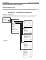
1
Instructions For Use
LTC 2600 Series
Video Multiplexers
IMPORTANT SAFEGUARDS
1. Read Instructions - All the safety and operating instructions should be
read before the unit is operated.
16.
Servicing - Do not attempt to service this unit yourself as opening or
removing covers may expose you to dangerous voltage or other
hazards. Refer all servicing to qualified service personnel.
17.
Damage Requiring Service - Unplug the unit from the outlet and
refer servicing to qualified service personnel under the following
conditions:
2. Retain Instructions - The safety and operating instructions should be
retained for future reference.
3. Heed Warnings - All warnings on the unit and in the operating
instructions should be adhered to.
a. When the power-supply cord or plug is damaged.
4. Follow Instructions - All operating and use instructions should be
followed.
c. If the unit has been exposed to rain or water.
b. If liquid has been spilled, or objects have fallen into the unit.
d. If the unit does not operate normally by following the operating
instructions. Adjust only those controls that are covered by the
operating instructions, as an improper adjustment of other
controls may result in damage and will often require extensive
work by a qualified technician to restore the unit to its normal
operation.
5. Cleaning - Unplug the unit from the outlet before cleaning. Do not
use liquid cleaners or aerosol cleaners. Use a damp cloth for cleaning.
6. Attachments - Do not use attachments not recommended by the
product manufacturer as they may cause hazards.
7. Water and Moisture - Do not use this unit near water - for example,
near a bath tub, wash bowl, kitchen sink, or laundry tub, in a wet
basement, near a swimming pool, in an unprotected outdoor
installation, or any area which is classified as a wet location.
e. If the unit has been dropped or the cabinet has been damaged.
f. When the unit exhibits a distinct change in performance--this
indicates a need for service.
8. Accessories - Do not place this unit on an unstable stand, tripod,
bracket, or mount.The unit may fall, causing serious injury to a person
and serious damage to the unit. Use only with a stand, tripod, bracket,
or mount recommended by the manufacturer, or sold with the
product. Any mounting of the unit should follow the manufacturer's
instructions, and should use a mounting accessory recommended by
the manufacturer.
An appliance and cart combination should be moved with
care. Quick stops, excessive force, and uneven surfaces may
cause the appliance and cart combination to overturn.
18.
Replacement Parts - When replacement parts are required, be sure
the service technician has used replacement parts specified by the
manufacturer or have the same characteristics as the original part.
Unauthorized substitutions may result in fire, electric shock or other
hazards.
19.
Safety Check - Upon completion of any service or repairs to this unit,
ask the service technician to perform safety checks to determine that
the unit is in proper operating condition.
20.
Coax Grounding - If an outside cable system is connected to the unit,
be sure the cable system is grounded. U.S.A. models only--Section 810
of the National Electrical Code, ANSI/NFPA No.70-1981, provides
information with respect to proper grounding of the mount and
supporting structure, grounding of the coax to a discharge unit, size
of grounding conductors, location of discharge unit, connection to
grounding electrodes, and requirements for the grounding electrode.
21.
Lightning - For added protection of this unit during a lightning storm,
or when it is left unattended and unused for long periods of time,
unplug it from the wall outlet and disconnect the cable system.This
will prevent damage to the unit due to lightning and power-line
surges.
9. Ventilation - Openings in the enclosure, if any, are provided for
ventilation and to ensure reliable operation of the unit and to protect
it from overheating.These openings must not be blocked or covered.
This unit should not be placed in a built-in installation unless proper
ventilation is provided or the manufacturer's instructions have been
adhered to.
10.
Power Sources - This unit should be operated only from the type of
power source indicated on the marking label. If you are not sure of
the type of power supply you plan to use, consult your appliance
dealer or local power company. For units intended to operate from
battery power, or other sources, refer to the operating instructions.
11.
Grounding or Polarization - This unit may be equipped with a
polarized alternating-current line plug (a plug having one blade wider
than the other).This plug will fit into the power outlet only one way.
This is a safety feature. If you are unable to insert the plug fully into
the outlet, try reversing the plug. If the plug should still fail to fit,
contact your electrician to replace your obsolete outlet. Do not
defeat the safety purpose of the polarized plug.
FCC & ICES INFORMATION
(U.S.A. and Canadian Models Only)
WARNING - This equipment has been tested and found to comply with
the limits for a Class A digital device, pursuant to Part 15 of the FCC Rules
and ICES-003 of Industry Canada.These limits are designed to provide
reasonable protection against harmful interference when the equipment is
operated in a commercial environment. This equipment generates, uses,
and can radiate radio frequency energy and, if not installed and used in
accordance with the instruction manual, may cause harmful interference to
radio communications. Operation of this equipment in a residential area is
likely to cause harmful interference in which case the user will be required
to correct the interference at his own expense. Intentional or unintentional
changes or modifications not expressly approved by the party responsible
for compliance shall not be made. Any such changes or modifications could
void the user's authority to operate the equipment.
Alternately, this unit may be equipped with a 3-wire grounding-type
plug, a plug having a third (grounding) pin.This plug will only fit into a
grounding-type power outlet.This is a safety feature. If you are unable
to insert the plug into the outlet, contact your electrician to replace
your obsolete outlet. Do not defeat the safety purpose of the
grounding-type plug.
12.
Power-Cord Protection - Power-supply cords should be routed so
that they are not likely to be walked on or pinched by items placed
upon or against them, paying particular attention to cords and plugs,
convenience receptacles, and the point where they exit from the
appliance.
13.
Power Lines - An outdoor system should not be located in the
vicinity of overhead power lines or other electric light or power
circuits, or where it can fall into such power lines or circuits.When
installing an outdoor system, extreme care should be taken to keep
from touching such power lines or circuits as contact with them
might be fatal. U.S.A. models only - refer to the National Electrical
Code Article 820 regarding installation of CATV systems.
14.
Overloading - Do not overload outlets and extension cords as this
can result in a risk of fire or electric shock.
15.
Object and Liquid Entry - Never push objects of any kind into this
unit through openings as they may touch dangerous voltage points or
short-out parts that could result in a fire or electric shock. Never
spill liquid of any kind on the unit.
If necessary, the user should consult the dealer or an experienced
radio/television technician for corrective action .The user may find the
following booklet prepared by the Federal Communications Commission
helpful: "How to Identify and Resolve Radio-TV Interference Problems".
This booklet is available from the U.S. Government Printing Office,
Washington, DC 20402, Stock No.004-000-00345-4.
Warning: This is a Class A product. In a domestic environment this
product may cause radio interference in which case the user may be
required to take adequate measures.
3
SAFETY PRECAUTIONS
SECURITE
C A U T IO N
A T T E N T IO N
R IS K O F E L E C T R IC
S H O C K . D O N O T O P E N !
R IS Q U E D E C H O C E L E C T R IQ U E .
N E P A S O U V R IR .
Danger: Pour ‚éviter tout risque d'électrocution, ne pas
ouvrir le boîtier. Il n'y a pas de pièces remplaçables à
l'intérieur. Pour toute révision, s'adresser à un
technicien spécialisé.
Caution: To reduce the risk of electrical shock,
do not open covers. No user serviceable parts inside.
Refer servicing to qualified service personnel
This label may appear on the bottom of the unit due to space limitations.
En raison de limitation de place, cette étiquette peut être placée sur le
dessous de l'appareil.
The lightning flash with an arrowhead symbol, within an
equilateral triangle, is intended to alert the user to the presence
of uninsulated "dangerous voltage" within the product's
enclosure that may be of sufficient magnitude to constitute a
risk of electric shock to persons.
L'éclair fléché dans un triangle équilatéral, avertit l'utilisateur de
la présence d'une "tension dangereuse" non isolée à l'intérieur
de l'appareil et d'une valeur suffisante pour constituer un risque
d'électrocution.
The exclamation point within an equilateral triangle is intended
to alert the user to presence of important operating and
maintenance (servicing) instructions in the literature
accompanying the appliance.
Le point d'exclamation contenu dans un triangle équilatéral,
avertit l'utilisateur de la présence, dans la documentation qui
accompagne l'appareil, de consignes d'utilisation et de
maintenance importantes.
Attention: Pour éviter le risque
d'électrocution ou d'incendie, ne pas exposer
à la pluie ou à l'humidité un appareil non
conçu pour une utilisation extérieure.
Warning:To prevent fire or shock hazard, do not
expose units not specifically designed for
outdoor use to rain or moisture.
Attention: Installation should be performed by qualified
service personnel only in accordance with the National
Electrical Code or applicable local codes.
Attention: L'installation doit être effectuée uniquement par du
personnel de service qualifié conformément à la réglementation
du Code Electrique National ou à la réglementation locale.
Power Disconnect. Units with or without ON-OFF switches
have power supplied to the unit whenever the power cord is
inserted into the power source; however, the unit is operational
only when the ON-OFF switch is in the ON position. The
power cord is the main power disconnect for all units.
Disjonction de l'alimentation. Les appareils avec ou sans
commutateurs ON-OFF sont alimentés à chaque fois que le
cordon d'alimentation est branché à la source d'alimentation;
toutefois, les appareils disposant de commutateurs ON-OFF ne
fonctionnnent que lorsque le commutateur ON-OFF est sur la
position ON. Le cordon d'alimentation est la disjonction
d'alimentation principale pour tous les appareils.
4
SICHERHEITSVORKEHRUNGEN
PRECAUCIONES DE SEGURIDAD
V O R S IC H T
P R E C A U C IO N
R IE S G O D E C H O Q U E
E L E C T R IC O . ¡N O A B R IR !
R IS IK O E IN E S E L E K T R IS C H E N
S C H L A G E S N IC H T Ö F F N E N !
Precaucion: Para Reducir El Riesgo De Choque Eléctrico,
Favor No Abrir La Cubierta. Este Equipo No Consta De
Piezas O Partes Que Requieren Servicio O Mantenimiento.
Para Reparaciones Favor Referirse A Un Técnico Calificado.
VORSICHT: Um einen elektrischen schlag zu vermeiden,
abdeckung nicht entfernen. Wartungen aller art
qualifiziertem personal überlassen.
Debido a limitaciones de espacio, esta etiqueta puede aparecer en la parte
inferior de la unidad.
Aus Platzgründen kann diese Warnung auf der Unterseite des Gerätes
angebracht sein.
El símbolo representado por un relámpago con punta de flecha
dentro de un triángulo equilátero, se muestra con el objetivo de
alertar al usuario que existen "voltages peligrosos" sin
aislamiento, dentro de la cubierta de la unidad. Dichos voltages
pueden ser de tal magnitud que constituyen un riesgo de
choque eléctrico a personas.
Das Blitzsymbol im gleichseitigen Dreieck soll den Benutzer auf
nicht isolierte “Hochspannung” im Gehäuse aufmerksam
machen, die eventuell stark genug ist, um einen elektrischen
Schlag zu verursachen.
Das Ausrufezeichen im gleichseitigen Dreieck soll den Benutzer
auf wichtige Bedienungs- und Wartungsanleitungen in der dem
Gerät beigefügten Literatur aufmerksam machen.
El símbolo de exclamación dentro de un triángulo equilátero, se
muestra con el objetivo de alertar al ususario de que
instrucciones de operación y mantenimiento importantes
acompañan al equipo.
Warnung
Um Feuer oder elektrische Schläge zu vermeiden, setzen
Sie das Gerät niemals Regen oder Feuchtigkeit aus.
Peligro
Para evitar el peligro de incendio ó choque eléctrico, no
exponga a la lluvia ó humedad, equipos que no han sido
para uso exterior.
Achtung! Die Installation sollte nur von qualifiziertem
Kundendienstpersonal gemäß jeweilig zutreffender
Elektrovorschriften ausgeführt werden.
Atención: La instalación de este equipo debe ser realizada por
personal capacitado, solo en acuerdo, y en cumplimiento de
normas del "National Electric Code" (Código Eléctrico
Nacional) ó las normas del Gobierno Nacional Local.
Netzanschluß. Geräte mit oder ohne Netzschalter haben
Spannung am Gerät anliegen, sobald der Netzstecker in die
Steckdose gesteckt wird. Das Gerät ist jedoch nur
betriebsbereit, wenn der Netzschalter (EIN/AUS) auf EIN steht.
Wenn man das Netzkabel aus der Steckdose zieht, dann ist die
Spannungszuführung zum Gerät vollkommen unterbrochen.
Para Desconectar la Alimentación: Unidades no equipadas
con interruptores ON/OFF, son alimentadas cuando el cable de
alimentación es conectado a la corriente eléctrica. Las unidades
equipadas con interruptores son alimentadas de igual forma,
pero adicionalmente requieren que el interruptor esté
posicionado en ON. El cable de alimentación es el medio
principal de desconexión del equipo.
WARNING: Electrostatic-sensitive device. Use
proper CMOS/MOSFET handling precautions to avoid
electrostatic discharge.
A T T E N T IO N
O B S E R V E
F O R
E L E C
S E N S IT
P R
H A N
T R O
IV E
E C A U T IO N S
D L IN G
S T A T IC
D E V IC E S
NOTE: Grounded wrist straps must be worn and
proper ESD safety precautions observed when
handling the electrostatic-sensitive printed circuit boards.
5
LTC 2600 Series
Contents
Section IMPORTANT SAFEGUARDS . . . . . . . . . . . . . . . . . . . . . . . . . . . . . .3
Safety Precautions . . . . . . . . . . . . . . . . . . . . . . . . . . . . . . . . . . . . . . . . . . . . . . . . . . . . . . . . . . . . . . . . . .4
Section 1: introduction to the ltc 2600 series video multiplexer . . . . . . . . . .7
1.1 Unpacking . . . . . . . . . . . . . . . . . . . . . . . . . . . . . . . . . . . . . . . . . . . . . . . . . . . . . . . . . . . . . . . . . . . . .7
1.2 Service . . . . . . . . . . . . . . . . . . . . . . . . . . . . . . . . . . . . . . . . . . . . . . . . . . . . . . . . . . . . . . . . . . . . . . .7
1.3 Understanding Video Multiplexers . . . . . . . . . . . . . . . . . . . . . . . . . . . . . . . . . . . . . . . . . . . . . . . . . . .7
Section 2: INSTALLING THE VIDEO MULTIPLEXER . . . . . . . . . . . . . . . . . .9
2.1
2.2
2.3
3.2
Mounting . . . . . . . . . . . . . . . . . . . . . . . .
Connecting the Video Multiplexer System
Programming . . . . . . . . . . . . . . . . . . . . .
Live (Display) . . . . . . . . . . . . . . . . . . . . .
..
.
..
..
.
.
.
.
.
.
.
.
.
.
.
.
.
.
.
.
.
.
.
.
.
.
.
.
.
.
.
.
.
.
.
.
.
.
.
.
.
.
.
.
.
.
.
.
.
.
.
.
.
.
.
.
.
.
.
.
.
.
.
.
.
.
.
.
.
.
.
.
.
.
.
.
.
.
.
.
.
.
.
.
.
.
.
.
.
.
.
.
.
.
.
.
.
.
.
.
.
.
.
.
.
.
.
.
.
.
.
.
.
.
.
.
.
.
.
.
.
.
.
.
...........
...........
...........
...........
.
.
.
.
.
.
.
.
.9
.9
.11
.17
SECTION 3: OPERATING THE LTC 2600 SERIES VIDEO MULTIPLEXER .17
3.1
3.2
3.3
3.4
3.5
3.6
3.7
Guide to Multiplexer Operation
Live (Display) . . . . . . . . . . . . . .
Record . . . . . . . . . . . . . . . . . .
Playback . . . . . . . . . . . . . . . . . .
Combined Modes . . . . . . . . . .
Security Lockout . . . . . . . . . . .
VCR Mode . . . . . . . . . . . . . . .
.
.
.
.
.
.
.
.
.
.
.
.
.
.
.
.
.
.
.
.
.
.
.
.
.
.
.
.
.
.
.
.
.
.
.
.
.
.
.
.
.
.
.
.
.
.
.
.
.
.
.
.
.
.
.
.
.
.
.
.
.
.
.
.
.
.
.
.
.
.
.
.
.
.
.
.
.
.
.
.
.
.
.
.
.
.
.
.
.
.
.
.
.
.
.
.
.
.
.
.
.
.
.
.
.
.
.
.
.
.
.
.
.
.
.
.
.
.
.
.
.
.
.
.
.
.
.
.
.
.
.
.
.
.
.
.
.
.
.
.
.
.
.
.
.
.
.
.
.
.
.
.
.
.
.
.
.
.
.
.
.
.
.
.
.
.
.
.
.
.
.
.
.
.
.
.
.
.
.
.
.
.
.
.
.
.
.
.
.
.
.
.
.
.
.
.
.
.
.
.
.
.
.
.
.
.
.
.
.
.
.
.
.
.
.
.
.
.
.
.
.
.
.
.
.
.
.
.
.
.
.
.
.
.
.
.
.
.
.
.
.
.
.
.
.
.
.
.
.
.
.
.
.
.
.
.
.
.
.
.
.
.
.
.
.
..........
..........
..........
..........
..........
..........
..........
.
.
.
.
.
.
.
.
.
.
.
.
.
.
.
.
.
.
.
.
.
.
.
.
.
.
.
.
.17
.17
.18
.18
.19
.19
.19
SECTION 4: ADVANCED PROGRAMMING & OPERATION . . . . . . . . . . . .20
4.1 Guide to Advanced Functions . . . . . . . . . . . . . . . . . . . . . . . . . . . . . . . . . . . . . . . . . . . . . . . . . . . . .
4.2 VCR Output (From the VCR Setup Menu) . . . . . . . . . . . . . . . . . . . . . . . . . . . . . . . . . . . . . . . . . . . .
4.3 Action Setup . . . . . . . . . . . . . . . . . . . . . . . . . . . . . . . . . . . . . . . . . . . . . . . . . . . . . . . . . . . . . . . . . .
4.4 Alarm Setup . . . . . . . . . . . . . . . . . . . . . . . . . . . . . . . . . . . . . . . . . . . . . . . . . . . . . . . . . . . . . . . . . . .
4.5 Camera Titles . . . . . . . . . . . . . . . . . . . . . . . . . . . . . . . . . . . . . . . . . . . . . . . . . . . . . . . . . . . . . . . . .
4.6 Sequences . . . . . . . . . . . . . . . . . . . . . . . . . . . . . . . . . . . . . . . . . . . . . . . . . . . . . . . . . . . . . . . . . . . .
4.7 Configure Setups . . . . . . . . . . . . . . . . . . . . . . . . . . . . . . . . . . . . . . . . . . . . . . . . . . . . . . . . . . . . . . .
4.8 Configure Display . . . . . . . . . . . . . . . . . . . . . . . . . . . . . . . . . . . . . . . . . . . . . . . . . . . . . . . . . . . . . .
4.9 Video Loss . . . . . . . . . . . . . . . . . . . . . . . . . . . . . . . . . . . . . . . . . . . . . . . . . . . . . . . . . . . . . . . . . . .
4.10 Default Settings . . . . . . . . . . . . . . . . . . . . . . . . . . . . . . . . . . . . . . . . . . . . . . . . . . . . . . . . . . . . . . .
4.11 Languages . . . . . . . . . . . . . . . . . . . . . . . . . . . . . . . . . . . . . . . . . . . . . . . . . . . . . . . . . . . . . . . . . . .
...............................................................................
.20
.20
.21
.23
.23
.23
.24
.24
.25
.25
.25
.25
SECTION 5: System4 MODEL FUNCTIONS . . . . . . . . . . . . . . . . . . . . . . . . .26
5.1
5.2
5.3
5.4
5.5
5.6
5.7
5.8
Guide to System4 Model Functions
Camera Sequences . . . . . . . . . . .
RS-232 Setup for PC/Printer/VCRs
LOG . . . . . . . . . . . . . . . . . . . . . .
Password . . . . . . . . . . . . . . . . . . .
Expand System Setup . . . . . . . . . .
System Keyboards . . . . . . . . . . . .
Keyboard Operation . . . . . . . . . .
. . . . . . . . . . . . . . . . . . . . . . . . . . . . . . . . . . . . . . . . . . . . . . . . . .26
. . . . . . . . . . . . . . . . . . . . . . . . . . . . . . . . . . . . . . . . . . . . . . . . . . .26
. . . . . . . . . . . . . . . . . . . . . . . . . . . . . . . . . . . . . . . . . . . . . . . . . .26
. . . . . . . . . . . . . . . . . . . . . . . . . . . . . . . . . . . . . . . . . . . . . . . . . . .26
. . . . . . . . . . . . . . . . . . . . . . . . . . . . . . . . . . . . . . . . . . . . . . . . . . .27
. . . . . . . . . . . . . . . . . . . . . . . . . . . . . . . . . . . . . . . . . . . . . . . . . . .27
. . . . . . . . . . . . . . . . . . . . . . . . . . . . . . . . . . . . . . . . . . . . . . . . . . .27
. . . . . . . . . . . . . . . . . . . . . . . . . . . . . . . . . . . . . . . . . . . . . . . . . . .28
Appendix A . . . . . . . . . . . . . . . . . . . . . . . . . . . . . . . . . . . . . . . . . . . . . . . . . . .30
Appendix B: SPECIAL APPLICATIONS . . . . . . . . . . . . . . . . . . . . . . . . . . . . .31
Appendix C: FACTORY DEFAULT SETTINGS . . . . . . . . . . . . . . . . . . . . . . . .35
Appendix D: PROGRAMMING REFERENCE . . . . . . . . . . . . . . . . . . . . . . . . .38
Appendix E: QUICK FUNCTION KEYS . . . . . . . . . . . . . . . . . . . . . . . . . . . . .45
6
LTC 2600 Series
Section 1 Introduction
SECTION 1: INTRODUCTION TO THE LTC 2600 SERIES
VIDEO MULTIPLEXER
1.1 Unpacking
Unpack carefully.This is electronic equipment and should be handled carefully.
Check for the following items:
• LTC 2600 Series Video Multiplexer
• Instuctions for use
• Quick Reference Guide
• One shielded cable with a 25-pin D-Type connector on one end. Used for Alarm/Accessory connections.
• Rack mount kit is included.
• One shielded cable with 15-pin D-type connector on one end. Use for Biphase output (LTC 2672, LTC 2680
Series only).
If an item appears to have been damaged in shipment, replace it properly in its carton and notify the shipper. If any
items are missing, notify your Philips Communication & Security Systems Sales Representative or Customer Service.
The shipping carton is the safest container in which the unit may be transported. Save it for possible future use.
1.2 Service
If the unit ever needs repair service, the customer should contact the nearest Philips Communication & Security
Systems Service Center for return authorization and shipping instructions.
Service Centers
U.S.A. & Canada: 800-366-2283
Mexico & Central America: 52-5-564-2726
Europe & Middle East: 44-1932-765666
South America: 54-1-956-0837
Austrailia: 61-2-888-9000
New Zealand: 64-4-237-7297
1.3 Understanding Video Multiplexers
The LTC2600 Series Video Multiplexers are designed to control multichannel recording and playback with the added
capability of multiscreen viewing. The units allow monitoring of multiple camera sites without the need for multiple
monitors and VCRs. They can be programmed easily via front panel control keys and on-screen display menus.
Video multiplexers are available in the following main categories:
• Standard Models provide high quality multiplexing. They are designed to be plug-and-play, therefore simplifying
installation.
• System4 Models provide a variety of advanced system features such as control via remote keypad, PC control,
system camera control, as well as enhanced multiplexing (e.g. two multiscreen outputs and two VCRs to increase
recording speed).
• Simplex Models allow live multiscreen monitor viewing or playback or VCR recording.
• Duplex Models allow live multiscreen monitor viewing or playback and at the same time, recording all video.
Note: See Appendix A for a detailed list of features.
7
LTC 2600 Series
Section 1 Introduction
Power
Model
No.
Mode
Rated
Voltage
Voltage
Range
Power
6 Channel
Standard Color Models
LTC 2622/50 Duplex
220 VAC, 50/60 Hz
LTC 2622/60 Duplex
120 VAC, 50/60 Hz
195.5 to 253
108 to 132
30 W
30 W
9 Channel
Standard Monochrome
LTC 2631/50 Simplex
LTC 2631/60 Simplex
LTC 2632/50 Duplex
LTC 2632/60 Duplex
Models
230 VAC, 50/60
120 VAC, 50/60
230 VAC, 50/60
120 VAC, 50/60
Hz
Hz
Hz
Hz
195.5 to 253
108 to 132
195.5 to 253
108 to 132
30 W
30 W
30 W
30 W
Standard Color Models
LTC 2641/50 Simplex
LTC 2641/60 Simplex
LTC 2642/50 Duplex
LTC 2642/60 Duplex
230 VAC, 50/60
120 VAC, 50/60
230 VAC, 50/60
120 VAC, 50/60
Hz
Hz
Hz
Hz
195.5 to 253
108 to 132
195.5 to 253
108 to 132
30 W
30 W
30 W
30 W
System4 Color Models
LTC 2672/50 Duplex
LTC 2672/60 Duplex
230 VAC, 50/60 Hz
120 VAC, 50/60 Hz
195.5 to 253
108 to 132
30 W
30 W
16 Channel
Standard Monochrome
LTC 2651/50 Simplex
LTC 2651/60 Simplex
LTC 2652/50 Duplex
LTC 2652/60 Duplex
Models
230 VAC, 50/60
120 VAC, 50/60
230 VAC, 50/60
120 VAC, 50/60
Hz
Hz
Hz
Hz
195.5 to 253
108 to 132
195.5 to 253
108 to 132
30 W
30 W
30 W
30 W
Standard Color Models
LTC 2661/50 Simplex
LTC 2661/60 Simplex
LTC 2662/50 Duplex
LTC 2662/60 Duplex
230 VAC, 50/60
120 VAC, 50/60
230 VAC, 50/60
120 VAC, 50/60
Hz
Hz
Hz
Hz
195.5 to 253
108 to 132
195.5 to 253
108 to 132
30 W
30 W
30 W
30 W
System4 Color Models
LTC 2681/50 Simplex
LTC 2681/60 Simplex
LTC 2682/50 Duplex
LTC 2682/60 Duplex
230 VAC, 50/60
120 VAC, 50/60
230 VAC, 50/60
120 VAC, 50/60
Hz
Hz
Hz
Hz
195.5 to 253
108 to 132
195.5 to 253
108 to 132
30 W
30 W
30 W
30 W
Video
PIR Sensor
Video
Video
Spot Monitor
Main Monitor
Philips
Philips
Up to 16 cameras
VCR
VCR
IN
OUT
MON B
MON A
1
2
3
4
5
6
7
8
9
10
11
12
13
VEXT In
ALARM
Out
In
Head Switching Pulse
VCR
Head Switching Pulse
Gnd
LTC 2600 Series
PIN 21 VEXT Input
Pin 25
Figure 1A:Typical Video Multiplexer System
8
14
15
16
LTC 2600 Series
Section 2 Installation
SECTION 2: INSTALLING THE VIDEO MULTIPLEXER
2.1 Mounting
The multiplexer is supplied as a desktop unit. If desired the unit may be rack mounted using the included rack
mount kit.
2.2 Connecting the Video Multiplexer System
1. Refer to Figures 2A and 2B for details on the input/output connections supplied by the multiplexer.
(Be sure to reference the appropriate drawing for your multiplexer model.)
2. Review the typical installation diagrams provided in Appendix B at the back of the manual, and determine
the number of cameras, monitors, and VCRs to be incorporated into the system.
3. Connect all peripherals (e.g. cameras, monitors,VCRs) to the corresponding inputs/outputs on the multiplexer
rear panel.
VCR
IN
Cameras
1-16
Mon A
VCR Out
VCR IN
Mon B
MON B
VCR
OUT
MON A
1
2
3
4
5
6
7
8
9
10
11
12
ALARM
Power
3032724-703
Alarm In/Out (Cable Supplied)
Pin
1
2
3
4
5
6
7
8
9
10
11
12
13
Color
Black
Brown
Red
Orange
Yellow
Green
Blue
Violet
Grey
White
White/Black
White/Brown
White/Red
Function
Alarm 1
Alarm 2
Alarm 3
Alarm 4
Alarm 5
Alarm 6
Alarm 7
Alarm 8
Alarm 9
Alarm 10
Alarm 11
Alarm 12
Alarm 13
Pin
14
15
16
17
18
19
20
21
22
23
24
25
Color
White/Orange
White/Yellow
White/Green
White/Blue
White/Violet
White/Greg
Wht/Blk/Brn
Wht/Blk/Red
Wht/Blk/Org
Wht/Blk/Yel
Wht/Blk/Grn
Wht/Blk/Blu
Function
Alarm 14
Alarm 15
Alarm 16
Video Loss Relay 1
Video Loss Relay 1
Alarm Relay 1
Alarm Relay 1
Vext Input 1
N/C
N/C
N/C
Gnd
Figure 2A: 16-Channel Back Panels
V C R
V C R
K E Y B D
V C R
IN
IN
M o n A
O u t
C a m e ra s
1 -1 6
M o n B
V C R
O U T
M O N B
M O N A
1
2
3
4
5
6
A L A R M /S D A
K e y B o a rd
A L A R M /S D A
P in
1
2
3
4
5
6
7
8
9
1 0
1 1
1 2
1 3
F u n
A la
A la
A la
A la
A la
A la
G n
V e
A la
A la
V id
V id
C o
c t
rm
rm
rm
rm
rm
rm
io n
1
2
3
4
5
6
x t
rm
rm
e o
e o
d e
In p u
R e
R e
L o s
L o s
1 -
d
t 1
la y
la y
s R
s R
1
1
e la y 1
e la y 1
P in
1 4
1 5
1 6
1 7
1 8
1 9
2 0
2 1
2 2
2 3
2 4
2 5
F u n c tio
C o d e 1
S h ie ld
C o d e 2
C o d e 2
S h ie ld
C o d e 3
C o d e 3
S h ie ld
C o d e 4
C o d e 4
S h ie ld
G n d
Figure 2B: 6-Channel Back Panels
9
n
+
+
-
+
-
+
13
14
15
16
LTC 2600 Series
Section 2 Installation
** When using Remote Keyboard LTC 2601/00 or LTC 2602/00,
to control Philips VCRs, please use the following connections.
From Console Port of System4 to RS-232 Port of Philips VCRs
Function
9 Pin D sub
Rx
2
Gnd
5
Tx
3
or purchase a S1383 cable.
*
Figure 2C: 16-Channel System4 Back Panels
* S-VHS (IN/OUT)
Limited Distance Need S-VHS VCR and S-VHS Tape
10
to
25 Pin D sub
2
1+7
3
LTC 2600 Series
Section 2 Installation
2.3 Programming
1. When all connections have been successfully completed, apply power to the system.
2. Upon power up, the multiplexer will be using the factory-set default parameters. (See Appendix C for a
complete listing of the Factory Default Settings.)
3. Refer to Figures 2D, 2E and 2F for a detailed review of the multiplexer front panel controls which will be used
in programming. Summaries of the control functions (primary and secondary) and the LED indicators are
provided in the adjacent tables.
FREEZE
LED INDICATOR
CAMEO
QUAD
MULTI
FULL
ACTION
CLEAR
ZOOM
CAMEO
ALARM
CLEAR
ALT
CAMERA
KEYBOARD
#
Video Multiplexer
ACT
ALM
1
2
3
4
5
6
VCR
9
10
SEQ
PLAY
REC
11
12
MENU
DOWN
LEFT
8
7
MON B
RIGHT
Figure 2D: 16-Channel Front Panel
#
Video Multiplexer
ACT
ALM
1
2
3
4
VCR
5
6
7
SEQ
PLAY
REC
Figure 2E: 9-Channel Front Panel
V id e o M u ltip le x e r
A L T
A C T
14
15
16
POWER LED
SELECT
UP
13
#
A L M
1
2
V C R
3
4
5
.6
S E Q
P L A Y
R E C
Figure 2F: 6-Channel Front Panel
11
8
9
LTC 2600 Series
Section 2 Installation
Indicators
LED
POWER
ALT
RECORD
PLAYBACK
VCR Test
MON B
SEQ
CAMEO
CAMERA
KEYPAD
ZOOM
ACT
ALM
Indication
Power supplied to unit
Primary indication: Alternate
functions (Flashing): Camerato cameo mode (ALT + SELECT)
Record mode enabled
Playback mode enabled
VCR Test enabled
Monitor B enabled (Front panel keys
control monitor B display)
Sequence mode enabled
Cameo mode enabled
(Camera keys control cameo images
Camera mode enabled
(Camera keys control camera images)
Numeric mode enabled
(Camera keys act as numeric keys)
Enlarge/zoom mode enabled
Steady:Action is enabled
Flashing: Action has occurred
Steady:Alarm is enabled
Flashing:Alarm has occurred.
Primary Selections
Description
Icon
FULL
QUAD
MULTI
CAMEO
ZOOM
FREEZE
ALT
ACTION CLEAR
ACT
ALARM CLEAR
ALM
12
Controls
Secondary Selections
Description
Icon
LEFT
UP
DOWN
RIGHT
MENU
SELECT
LTC 2600 Series
Section 2 Installation
4. The multiplexer is programmed through on-screen menus which include access to on-screen HELP information.
The menus will be displayed on Monitor A in the system.
5. To access the menu screens, press the ALT key
followed by the MENU key
.
6. The Main Menu (as shown below) displays two setup options: Quick Setup and Advanced Setup.
- Quick Setup will provide all the basic programming necessary for typical systems
- Choose Advanced Setup when configuration requires such functions as alarm, motion, etc.
To perform the Advanced Setup for customized system configurations, first select Advanced Setup from the
main menu; then program the Time/Date, Autoset, and VCR setups as described in the following paragraphs; and
then refer to Section 4 for additional programming instructions.
MAIN MENU 1.00
SETUP 1
>QUICK SETUP
ADVANCED SETUP
Choose:SELECT More:V
Exit:ZOOM
Each menu screen includes two lines at the bottom showing the options that can be selected. These options
are:
CHOOSE
Press SELECT key
MORE
Use direction keys
EXIT
Press ZOOM key
HELP
Press ALT key
DEFAULT
Press FREEZE key
ENTER CHARACTER
Use direction keys to scroll through characters
When the SELECT key
is pressed, all programmed settings are saved into non-volatile memory.
NOTE: A complete listing of all menu trees is provided at the back of the manual in Appendix D.
7. For typical video multiplexer system operations, select the Quick Setup option from the Main Menu.
QUICK SETUP
SETUP 1
>TIME/DATE
AUTOSET
VCR SETUP
Choose:SELECT More:V
Exit:ZOOM
NOTE: The Quick Setup program includes: Time/Date, AutoSet, and VCR setup. Quick Setup guides you
through all of these steps. If for any reason you need further information, consult the built-in HELP feature by
pressing the ALT key .
13
LTC 2600 Series
Section 2 Installation
8. Select Time/Date from the Quick Setup menu. Enter the time format (12 or 24 hours), time, date format
(dd/mm/yyyy; mm/dd/yyyy; yyyy/mm/dd) and date information as requested. Use the direction (arrow) keys to
move the cursor and to scroll through parameter settings. Use the SELECT key
to choose the parameter
you want to program and to save your selections. When you have finished programming all time/date
parameters, use the ZOOM key
to return to the Quick Setup menu.
TIME/DATE
>TIME FORMAT
12hr
TIME
01:00:00AM
DATE FORMAT MM/DD/YYYY
DATE
01/01/1998
Choose:SELECT
More:V
Edit: ><
Exit:ZOOM
NOTE: The multiplexer encodes the time/date onto each field of video sent to the VCR. In the Live Display mode,
the time/date is displayed on the monitor. If the VCR's time/date display is ON, each screen in the playback mode
will also show the time/date. (You may want to switch the VCR time/date display OFF.)
9. Select AutoSet from the Quick Setup menu to automatically configure the video multiplexer for the number of
cameras connected. (A sample AutoSet menu is shown below.) Recording, sequence, and video loss list are also
configured via this menu.
10. Selecting AUTOSET ALL BELOW will automatically set the record list, sequence, and video loss list (according
to the number of camera inputs detected by the multiplexer). Selecting any of the other options in this menu
will set only the selected option.
AUTOSET
SETUP 1
>AUTOSET ALL BELOW
RECORD LIST
VIDEO LOSS LIST
SEQUENCES
Choose:SELECT More:V
Exit:ZOOM
11. When Autoset is completed, a message indicating so will be displayed for nine seconds. The camera inputs
detected in the setup process are also displayed as shown in this sample screen.
AUTOSET ALL
SETUP 1
01 02 03 04 05 06 -- -- --- -- -- -- -- -- -- -- -- -- -The above cameras were
included in selected system
list(s).
HIT ANY KEYTO CONTINUE
14
LTC 2600 Series
Section 2 Installation
12. Return to the Quick Setup main menu by pressing the zoom key. Continue by selecting VCR Setup (menu
shown below).
VCR SETUP
SETUP 1
>RECORD SETUP *VCR OUT*
PLAYBACK FORMAT LTC2600
RECORD LOCK
OFF
VCR SETUP
SETUP 1
>RECORD SETUP *VCR OUT*
RECORD SETUP *MON B*
PLAYBACK FORMAT LTC2600
RECORD FORMAT
LTC2600
RECORD LOCK
OFF
Choose:SELECT
Choose:SELECT
More:V
Exit:ZOOM
Standard Model Display.
More:V
Exit:ZOOM
LTC 2672 and LTC 2682 Series Display
(System4 Duplex) only.
NOTE: The LTC 2600 Series multiplexers are configured to record and playback from a wide range of VCRs.
The VCR provides a pulse (VEXT) each time a video field is recorded to tape. This signal lets the multiplexer
know that it can switch to a new camera. This feature also simplifies installation by synchronizing the normal
and alarm recording speeds. You will need to decide how you are going to synchronize the multiplexer and the
VCR. The options are:
(a) Connect and enable the VEXT output from the VCR and then choose the recording speed of the VCR. This
is the simplest and recommended method of synchronizing the multiplexer to the VCR. (Follow steps 13-14).
(b) If VEXT is not available, specify the VCR model and time lapse mode. Begin at step 15 (skip 13-14).
13. Connect the VEXT output from the VCR (CAM SW Out or Record Out) to Pin 21 (White/Black/Red) and
Ground to Pin 25 (White/Black/Blue) of the Alarm In/Out (cable supplied).
14. From the VCR Setup menu, select RECORD SETUP, then move to the VEXT INPUT selection. Switch it to the
ON setting (the factory default is OFF).
RECORD SETUP
*VCR OUT* SETUP 1
>VEXT INPUT
SELECT VCR
TIME LAPSE
Choose:SELECT
OFF
More:V
Exit:ZOOM
15.The alternate method for synchronization of the multiplexer and the VCR requires (a) selecting the appropriate
VCR model, and then (b) selecting the identical setting in the VCR time-lapse menu.
15
LTC 2600 Series
Section 2 Installation
16. From the VCR Setup menu, select RECORD SETUP, then SELECT VCR. Scroll through the different selections
listed with the TYPE parameter until you find your VCR model.
SELECT VCR
*VCR OUT* SETUP 1
>TYPE:PHILIPS TC3991 HD
EDIT CUSTOM VCR
Choose:SELECT More:V
Edit: ><
Exit:ZOOM
17. After you select a VCR model, use the SELECT key
to move to the TIMELAPSE Mode menu.
NOTE: When you specify the VCR model, the multiplexer will present the time-lapse settings in the same
format as the VCR. Ensure the same setting is entered in the VCR timelapse menu.
NOTE: If the type of VCR that is being used is not listed in the SELECT VCR menu, choose the CUSTOM VCR
option. Up to six custom setups can be stored in the VCR list. The field rate must be determined for each of the
VCR timelapse modes. This figure may be available in the VCR's instruction manual or by contacting the VCR
manufacturer's technical support. Enter this information in the timelapse menu.
18. Optional Programming: Playback Format
To playback a tape recorded on another multiplexer manufacturer, set the Playback Format option accordingly.
From the VCR Setup menu, select the PLAYBACK FORMAT option, and then select the appropriate tape
format. (The factory-set default for this option is LTC 2600 format.)
PLAYBACK FORMAT options are:
- LTC 2600 (Same as TC82XXC,TC 825X-X Series)
- TC8298B Series (Same as TC82XXA Series)
- 7 Bit (Same as UniplexII, Sprite Series)
- 12 Bit (Same as MV90X Series)
19. Optional Programming: Record Lock
When enabled (ON), this feature locks the multiplexer in the record mode; recording cannot be stopped from
the front panel or keyboard unless the lock option is turned OFF in the VCR Setup menu.
20. Optional Programming: Record Format
System4 provides the capability of recording in two types of teletext formats. this allows for reverse
compatibility to the TC82XX Series multiplexers.The two types are TC8298B and LTC 2600.
TC8298B (Includes TC82XXA,TC82XXB Series)
LTC 2600 (Includes TC82XXC Series)
Note: For information regarding quick function keys enabling “instant access” to the programming lists on the
LTC 2600 Video Multiplexer, please refer to Appendix E at the back of this book.
16
LTC 2600 Series
Section 3 Operation
SECTION 3: OPERATING THE LTC 2600 SERIES VIDEO
MULTIPLEXER
3.1 Guide to Multiplexer Operation
Operating the LTC 2600 Series Video Multiplexer requires a general knowledge of basic and combined operating
modes as described in this section. Basic operating modes are: LIVE (Display), RECORD, and PLAYBACK. Duplex
multiplexer models provide combinations of the basic modes (e.g. simultaneous recording plus playback).
When operating access is a concern, the multiplexer's security lockout feature can be enabled. Three levels of
access are provided as described at the end of this section.
3.2 Live (Display)
Live camera pictures can be displayed on monitors A and B.
Monitor A is the main functional monitor and can be displayed in FULL , QUAD , MULTI
. All alarm, action,
and video loss warnings are displayed on this monitor.
Monitor B Under normal operating modes, Monitor B will display the selected camera in full screen or sequencing
only. When an alarm or action input is detected, the corresponding camera picture with the flashing Alarm/Action
indicator will be displayed on Monitor B for the programmed dwell time. When multiple alarms or actions occur,
camera pictures will be sequenced on Monitor B at the two second dwell time.
For LTC 2672 and LTC 2682 series (System4 Duplex) Only: Multiscreen display modes can be displayed on
both Monitors (A and B). All alarm action and video loss warnings are displayed on both monitors.The alarm/action
callup will occur only when monitor B is in full screen mode.
Displaying Live Camera Pictures
Full Screen Display: Shows one camera, full screen on one monitor. Press the FULL SCREEN key
on the
front panel, and then press the appropriate camera number key for the camera you wish to be displayed.
Quad Screen Display: Divides the screen into four separate areas. Press the QUAD key
once to enable the
feature. Press the key repeatedly to toggle through different viewing configurations. Pressing
ALT,
then SEQ will sequence through all quad screens.
Multiscreen Display: Enabling this feature shows different multiscreen configuration.
6 channel: 5+1
9 channel: 4+3, 3X3
16 channel: 4+3, 8+2, 12+1, 3X3, and 4X4
Press the MULTI key
repeatedly to toggle through the different selections. (When the MULTI key is pressed
and the multiplexer is already in the multiscreen mode, the screen display advances to the next type of multiscreen
display.)
Cameo Mode: When in MULTI or QUAD modes, the screen area where a camera is displayed is called a
CAMEO. Note that the numbered front panel keys can refer to either cameras or cameos. Press the CAMEO key
to toggle the operation of these keys to the cameo function. (The CAMEO LED is illuminated when the
multiplexer is in the CAMEO mode.) Press the CAMEO key again to revert to the camera function.
Cameras can be assigned to any selected cameo and can be changed as often as required. This can be done by one
of the following:
• Assigning all cameras: Press the ALT key
.The ALT LED will flash, then press the SELECT key
. The
first cameo will be selected and show a flashing camera title. By pressing the desired camera key, that camera
will be assigned to the cameo, and the next cameo is automatically selected (shown by the flashing camera
titles). Again press the selected camera key, this is assigned and the process repeated until all cameos have been
assigned a camera. Press the ALT key to exit.
• Individual assignments: In the MULTI or QUAD mode, the Camera keys are assigned as Cameo keys
automatically. Select relevant cameo key, 1 to 16. The relevant cameo is selected. Press the CAMEO key
.
The cameo keys revert back to selecting cameras. Press camera key to assign the selected camera to cameo.
17
LTC 2600 Series
Section 3 Operation
Zoom
: Enables the active camera display (a cameo in multi or quad display) to be digitally enlarged by a factor
of 2:1. "Zoom" will be displayed on the monitor screen. Selecting any other camera (using the camera keys) will
display that camera image in full screen enlarged mode. Use the arrow keys to pan/tilt the enlarged picture to
allow closer inspection of any part of the selected image.
Freeze
: Holds the selected camera picture on either full screen or cameo. The currently selected camera
image will be frozen, and "FREEZE" will be displayed on the screen. This feature allows closer inspection of any part
of the selected image. Press the FREEZE key again to release the image from this function. Freeze a different
camera image by selecting another camera with the camera keys and pressing the FREEZE key again. Changing the
display screen mode releases the freeze mode from all cameos.
Alarms and Actions: When an alarm or action condition occurs, the corresponding camera picture is displayed in
full screen on Monitor B, the ALM
or ACT
LED flashes, "ALARM"/"ACTION" will also flash on Monitor A.
Clearing an Alarm/Action will stop any recording associated with that function. The method of clearing alarms or
action conditions depends on your multiplexer model.
Clearing Alarm/Action:
Standard Models: Press the ALM
or ACT
key, and all alarms/actions will be reset.
System4 Models:
Manual Reset Enabled: Press the ALM
or ACT key, and all alarms/actions will be reset.
Manual Reset Disabled: All alarms/actions will follow the Action Dwell Time as programmed in the
Alarm/Action Setup menu.
Camera History Enabled: Alert the operator that an action or alarm has occurred even if the action
condition has cleared.When enabled, press the ALM
or ACT
key. The front panel keys will flash
for cameras that are in Alarm/Action mode. The Alarm/Action condition can now be cleared by pressing
the individual camera keys, or all can be cleared simultaneously by pressing the ALM
or ACT
key
again.
NOTE: To better understand the parameters that affect how alarms/actions can be handled, refer to Advanced
Programming, Section 4.
3.3 Record
After the VCR format has been set up (as described in Section 2.3), the camera images that are to be recorded can
be programmed via the RECORD LIST. Enable this function from the AUTOSET or the VCR Setup menu, and
follow the screen prompts. Note that for System4 duplex multiplexer models, two record lists can be programmed,
enabling cameras to be recorded to two VCRs.
Any camera input can be recorded to a VCR after it has been listed in the multiplexer's RECORD LIST.
For Standard models, the RECORD LIST feature is programmed by enabling/disabling individual cameras
(up to 9 or 16). For System4 models, the RECORD LIST feature is customizable with up to 32 steps per list (i.e.
any camera, any order on the list).
To record live pictures:
1. Press the green ALT key
and then press REC. This key combination toggles on or off the record mode.
2. The designated camera video inputs from the record list will be recorded onto the VCR and will be available for
playback.
3.4 Playback
Recorded video can be played back on Monitor A in either FULL, QUAD, or MULTI screen modes. To playback the
recorded pictures:
1. Press the green ALT
key and then press PLAY.
2. The recorded camera video pictures will be displayed on Monitor A. You can alter the cameras displayed by
using the multiscreen display keys as described in Section 3.2.
18
LTC 2600 Series
Section 3 Operation
3.5 Combined Modes
The Duplex multiplexer models also provide combinations of the basic modes of operation as described in this
section.
Record Plus Multiscreen Display: (See Appendix B, Figure B1)
Allows live pictures to be displayed on Monitor A in either FULL, QUAD or MULTI screen mode, FULL screen or
sequencing of all cameras can be displayed on Monitor B while recording selected cameras onto the VCR.
Simultaneous Record plus Playback: (See Appendix B, Figure B2)
Allows recorded camera pictures to be played back and displayed on Monitor A in either FULL, QUAD or MULTI
screen mode, live FULL screen display of the selected camera picture or sequencing all cameras on Monitor B, and
at the same time, record the selected live camera pictures onto VCR.Two VCRs are required for this operation.
Simultaneous Record to Two VCRs: (See Appendix B, Figure B3)
System4 duplex models allow:
• Display of full screen live video on Monitor A.
• Record the selected camera pictures (as defined in the VCR1 RECORD LIST) to VCR 1.
• Record the selected camera pictures (as defined in VCR2 RECORD LIST) to VCR 2.
Two VCRs are required for this operation--one to record the output from the VCR OUT connector and one to
record the output from the MON B connection (Monitor B becomes a VCR output for VCR 2). By using two
recorders, customized record lists can be generated for each VCR. For example, while the first VCR is recording
normally, the second VCR can be set-up to record only alarm or action video pictures.
To program the unit to operate in this mode, press ALT
, then 2, and then REC key.This will engage the
multiplexer to send video to both vcrs. ALT, REC will disable this option.
When not recording, the following mode can be programmed: (See Appendix B, Figure B4)
Live Multiscreen on Monitor A and Monitor B: The duplex unit provides two independent output monitors,
each with the capability to provide FULL, QUAD or MULTI screen display.
Simultaneous Playback plus Multiscreen Display: The System4 duplex models allow live pictures to be
displayed on Monitor B in either FULL, QUAD or MULTI screen mode, and playback recorded camera pictures to
be displayed on Monitor A in either FULL, QUAD or MULTI screen mode.
Simultaneous Playback on Monitor A and Monitor B: The System4 duplex models allow simultaneous
playback on both Monitors A and B of multiple recorded images. Monitor A is selectable for any screen display
mode, while Monitor B can select any of the recorded cameras in full screen display only. To perform simultaneous
playback, press ALT
, then 2, then PLAY.
3.6 Security Lockout
The LTC 2600 Series Multiplexer provides three levels of access to operation: (1_ Full Access, (2) Limited Access,
and (3) Lockout (i.e. No access/no front panel manipulation possible).
The key commands controlling this feature are:
QUAD + ZOOM + ALM
All user functions and menus.
QUAD + CAMEO + ALT
All user functions except menus.
QUAD + CAMEO + FREEZE
Lock out the front panel.
3.7 VCR Mode
Toggles between viewing the output of the VCR (the VCR monitor mode) and viewing a camera input. Press
ALT
, then VCR key and the VCR LED will light.The VCR mode is used to examine the video which will be
recorded by the VCR during recording, or adjusting the tracking for optimal playback picture of the VCR. It should
only be used if both the input and output of a single VCR are connected to the multiplexer.
19
LTC 2600 Series
Section 4 Advanced Programming
SECTION 4: ADVANCED PROGRAMMING & OPERATION
4.1 Guide to Advanced Functions
The following information is provided for advanced multiplexer system and customized system configurations. This
information is not necessary for typical, day-to-day operations of the multiplexer (see Sections 2 and 3).
Information is also provided in this section for changing factory-set default parameters (e.g. camera titles, display
configuration, etc.) to suit your specific recording/display needs. These advanced functions are accessed through the
Advanced Setup menu which is shown below. A complete listing of menu selections for Advanced Setup is included
in Appendix D.
ADVANCED SETUP
SETUP 1
>TIME/DATE
AUTOSET
VCR SETUP
ACTION SETUP
ALARM SETUP
CAMERA TITLES
SEQUENCES
CONFIGURE SETUP
CONFIGURE DISPLAY
VIDEOLOSS
DEFAULT SETTINGS
LANGUAGE
Choose:SELECT More:V
Exit:ZOOM
NOTE: Additional Advanced Setup menu selections are offered for System4 models. These include: PC
PRINTER, LOG, PASSWORD, and EXPAND SYSTEM. These functions are explained in Section 5 which contains
information that pertains only to System4 multiplexer models. This section also includes special programming
information for the Sequencing function.
NOTE: Since Time/Date, Autoset, and VCR Setup are covered in Section 2 as part of Quick Setup, this chapter
describes only the remaining advanced functions.
4.2 VCR Output (From the VCR Setup Menu)
The VCR OUTPUT relay controls external devices such as changing the recording speed when an action and/or
alarm occurs. The VCR output relay will remain active while there are active alarms or action. The following
functions can be programmed:
• Output: The output relay can be activated on an action, alarm, action and alarm or off, enabling the installer to
prioritize the recording of camera pictures.
• Output relay: The output relay can be set to operate as normally closed or normally open contacts.
• Alarm speed: The VCR recording speed can be set to match the alarm recording speed of the VCR for an
action/alarm input, ensuring that no part of any incident is missed.
Note that the System4 Duplex units provide two VCR output relays.
20
LTC 2600 Series
Section 4 Advanced Programming
4.3 Action Setup
<
The LTC 2600 Series multiplexer includes a Digital Motion Detection feature that detects movement within the
camera scene. When this feature is programmed and motion is detected, the record/display rates will increase.
Using the ACTION LIST facility, the priority of recording can be changed to include recording of camera pictures
and at the same time prioritize picture display on the monitor.
• Action Dwell: The action will be held for monitor display (full video on monitor B, when applicable) and
recording for the programmed duration (3 to 60 seconds).
• Action List: Selects cameras to have motion detection. Entering the ACTION LIST menu enables this list to
be customized to a specific configuration.
• Action Record: Defines if a selected camera is recorded to the VCR when an action input is detected. Action
camera(s) can be set to record in Exclusive or Interleave mode (refer to VCR setup section for programming
VCR response to action).
Exclusive mode allows recording only the camera inputs in which an action has been detected.
Interleave mode, all camera(s) in the record list are recorded; however, the camera(s) that are in action are
alternated between the non-action cameras.
• Action Zones: The screen is divided into a 14 X 16 grid (224 zones). Enabling or Disabling zones will allow
the installer to specify which areas of the scene will detect action. For example, for an outdoor application,
some of the scene includes a view of the sky. In this case the grid areas covering the sky can be disabled.
Once in the Action Zone setup, select the camera requiring Action Zone setup by depressing the
corresponding camera number.
To Enable zones, select the Menu key, ensure ZONE (EDIT:MENU) = ENABLE (X) is displayed. Move the
cursor using the up, down, left, and/or right arrow keys to enable zones. Enabled zones will display an X.
To Disable zones, select the Menu key, ensure ZONE (EDIT:MENU) = DISABLE (O) is displayed. Move
the cursor using the up, down, left, and/or right arrow keys to disable zones. Disabled zones will be
blank.
To select the Default Enabled Zones, select the FREEZE key (12 X 14 grid, 168 zones).
To exit the Action Zone setup, select the ZOOM key.
To edit the enabled zones Sensitivity and Number of Zones for Alarm, proceed to the Walkthrough
setup.
• Walkthrough: The Walkthrough section of the Action Alarm Setup will be required to set Action Zone
Sensitivity and Number of Zones for Alarm within the scene which require activation before the system will
acknowledge an Action Alarm. Sensitivity and zone activation settings may be tested and adjusted from this
menu screen.
Once in the Walkthrough setup, select the camera requiring Action Alarm setup by depressing the
corresponding camera number.
To adjust the Action Alarm zone Sensitivity requirement, selecting the key will decrease and using the
key will increase the zone sensitivity.
To establish Number of Zones for Alarm, selecting the < will decrease and using the > will increase the
amount of zones required to initiate an Action Alarm. Note:The Number of Zones for Alarm must be
equal to or less than the number of enabled zones.
Default settings for Sensitivity (MED) and Number of Zones for Alarm (10) can be achieved by
depressing the FREEZE key.
To exit the Walkthrough Program, select the ZOOM key.
<
21
LTC 2600 Series
•
•
•
•
•
Section 1 Introduction
Manual Reset (System4 models only):
Enable: Press ACT
key, and all action(s) will be reset.
Disable: All actions will follow the action dwell time as programmed.
Camera History (System4 models only): By switching on CAMERA HISTORY, the front panel keys will
flash for cameras that were in Action once the ACT
key is pressed. The Action can now be cleared by
pressing individual camera keys or all can be cleared at once by pressing the ACT key again.
Audible Alarm: The LTC 2600 Series provides an Audible alarm.
Enable: When an action occurs, the beeper will sound for the duration of the action. Press any key to turn
the beeper Off.
Disable: Beeper disable.
Action Output Relay: The multiplexer has one output relay for standard models and two for System4
models.These relays can be programmed to switch on for actions (refer to VCR Setup section for programming
relay response to action).
Multiple Actions: Individual actions will be recorded for the programmed ACTION DWELL time or until the
action is cleared. If two or more actions are active at the same time, video is alternately recorded until the
dwell time expires or the action conditions are cleared.
Action call-up is only viewed on MON B. For multiple actions, MON B will sequence the action video at
two-second intervals.
LTC 2622 series only: Action call-up is automatically viewed in cameo 1 of the multiscreen display mode.
For multiple actions, cameo 1 will sequence the action video at two-second intervals.
22
LTC 2600 Series
Section 4 Advanced Programming
4.4 Alarm Setup
Depending on your multiplexer model, up to 9 or 16 alarm inputs can be connected to the multiplexer and are
associated with their corresponding video input. Alarm inputs can be configured as normally open or normally
closed. These inputs correspond to the camera inputs so that when an alarm input is initiated, the respective
camera picture is displayed or recorded. (Figures in Section 2 illustrate the Alarm In/Out connections.)
• Alarm Dwell: The alarm will be held for monitor display (Full video on monitor B, when applicable) and
recording for the programmed duration (3 to 60 seconds).
• Transparent Alarm: If Alarm Dwell is set to FOLLOWS, Alarms will follow the alarm input.These alarms
cannot be cleared until the Alarm contact is reset.
• Alarm Lists: The alarm record list defines which cameras are recorded when there is an alarm.
• Alarm Recording: On receiving alarms, the multiplexer will adjust the Record List to record cameras in
alarm at a higher rate. Cameras in alarm can be recorded Exclusively or Interleaved with standard recording
(refer to VCR setup section for programming VCR response to alarm).
Exclusive mode allows recording only the camera inputs in which an alarm has occurred.
Interleave mode, all camera(s) in the record list are recorded; however, the camera(s) that are in alarm are
alternated between the non-alarm camera(s).
NOTE: Exclusive recording is recommended where near real-time recording of alarm events is required.
Recording of non-alarmed cameras cannot take place while alarms are present. To only record alarms,
set up desired Alarm Recording configuration as described above (Alarm List, Alarm Recording) and enable the
VCR Output Relay to activate the VCR (LTC 2600 Series must be in the Recording mode.)
• Audible Alarm: The LTC 2600 Series provides an audible alarm
Enable: When an alarm occurs, the beeper will sound for the duration of alarm. Press any key to turn
beeper off.
Disable: Beeper disable.
• Alarm Output Relay: The multiplexer has one output relay for standard models and two for System4
models. These relays can be programmed to switch on for alarms (refer to VCR Setup section for programming
relay response to alarms)
• Alarm Recording: Individual alarms will be recorded for the programmed ALARM DWELL time or until the
alarm is cleared. If two or more alarms are active at the same time, video is alternately recorded until the dwell
time expires or the alarm conditions are cleared.
• Manual Reset (System4 models only):
Enable: Press ALM
key, and all alarm(s) will be reset.
Disable: All alarms will follow the alarm dwell time as programmed.
• Camera History (System4 models only): By switching on CAMERA HISTORY, the front panel keys will
flash for cameras that were in Alarm once the ALM
key is pressed. Alarm can now be cleared by pressing
individual camera keys or all can be cleared at once by pressing the ALM
key again.
• Alarm Display:
Alarm call-up is only viewed on MON B. For multiple alarms, MON B will sequence the alarm video at
two-second intervals.
LTC 2622 series only. Alarm call-up is automatically viewed in cameo 1 of the multiscreen display mode.
For multiple alarms, cameo 1 will sequence the alarm video at two-second intervals.
4.5 Camera Titles
Each camera can be designated with a 16-character name, if desired. The factory-set default name for each camera
is simply a numerical designation (e.g. camera 01).
4.6 Sequences
•
•
•
Camera sequencing on Monitor A and Monitor B is a function available to all standard multiplexer models.
However, sequencing is a factory-set, non-programmable function for standard models (simply enable or disable
the function for each camera via the Advanced Setup menu).
Quad sequencing is a function available on Monitor A on standard model.There are four Quad screens available
and each Quad page can be customized to suit each application.
Camera sequencing is programmable for cameo 1 of the 5+1 multiscreen display mode of the LTC 2622 series.
23
LTC 2600 Series
Section 4 Advanced Programming
4.7 Configure Setups
The LTC 2600 Series multiplexer has the capability to provide up to six individually configured setups that are
retained in the multiplexer memory. By using these setups, the multiplexer can be programmed to automatically
change its mode of operation based on a timer setting. This allows different configurations to be used (e.g. day,
night, weekend and holidays).The timer provides seven days of programming with six individual programmable
windows per day. The following options can be programmed for each Setup:
Load Setup
• The setup can be configured and then loaded into memory.
Copy Setup
• A setup can be copied and then saved as another setup.
Setup Title
• Each setup can have an individual title of 12 characters. (This title will displayed on line two of the multiplexer
menus).
Time Events
• The Time Event function in the Configuration Setup menu allows each of the six setups to be programmed for
several parameters including: start time, duration, and frequency (daily schedule) of recording. A sample menu is
shown below. Note that these parameters must be set for each setup (1-6.)
TIME EVENTS
SETUP 1
>SETUP ON/OFF
ON
START TIME
12:00AM
DAYS
SMTWTFS
RUN ONE TIME
ON
RECORD
ON
Choose:SELECT More:V
Exit:ZOOM
The setup program can be set to run only once. This allows for individual events to be programmed and then run
only one time. After the event, the multiplexer reverts to its "normal" programmed setup(s).
4.8 Configure Display
The monitor displays can be configured to show time/date and camera titles.The format of the text can be
changed, as well as the border of the cameo picture.
• Time/Date: Each monitor can have the time/date display selected on or off. Note that the time and date are
only displayed per screen and not per cameo picture.
• Text: Each monitor can have the camera title display selected on or off. This ensures that the text can be
viewed regardless what type of background is shown, (i.e. very dark backgrounds can have white text displayed).
The text can be displayed in a number of formats as shown in the following chart.
Background
Clear
Clear
Clear
White
White
White
Gray
Gray
Gray
Black
Black
Black
Text
White
Gray
Black
Clear
Gray
Black
Clear
White
Black
Clear
White
Gray
24
LTC 2600 Series
•
•
•
Section 4 Advanced Programming
Cameo borders: The cameo border format can be selected, enabling easy definition of the picture. The
border can be set to: white, gray or black.
Screen position: Use the position command to select top, middle, or bottom of display for the location of the
time/date/camera title information.
Gain Control: To maintain constant video quality, each camera input has individual automatic gain circuits that
are suitable for most applications. Each input can manually adjust to optimize performance when desired.
4.9 Video Loss
The LTC 2600 Series detects loss of video from any camera input by monitoring the camera sync signal. When a
loss of video input occurs, the multiplexer provides an output which can be used to activate a warning device (e.g.
buzzer, warning light, videoloss message on screen) to alert the operator that a video signal from one of the system
cameras has been lost. Select the VIDEOLOSS function from the Advanced Setup menu to program the following
parameters:
• Videoloss List: Enable/disable individual cameras for the videoloss list.
• Videoloss Output: The videoloss output can be enabled or disabled.
• Videoloss Relay: The videoloss output relay can be set to operate as normally closed contacts or normally
open contacts.
4.10 Default Settings
The multiplexer is supplied with default parameters that are set up at the factory (see appendix). These settings
allow normal operation of the multiplexer, enabling easy installation, setup and use. However, any parameter can be
changed to suit local conditions or customized configurations.
If changes are made, you always have the option of returning to the default settings by selecting the DEFAULT
SETTINGS command in the Advanced Setup menu.
4.11 Languages
To simplify the setup process, the menus of the LTC 2600 Series can be displayed in any one of six different
languages.These are:
English
French
German
Spanish
Dutch
Italian
Simply choose LANGUAGES from the Advanced Setup menu, and make your selection.
25
LTC 2600 Series
Section 5 Enhanced Model Functions
SECTION 5: SYSTEM4 MODEL FUNCTIONS
5.1 Guide to System4 Model Functions
The following information pertains to System4 multiplexer models only. These advanced programming and
operating functions, which are accessed through the Advanced Setup menu, include: CAMERA SEQUENCES, PC
PRINTER SETUP, LOG, PASSWORD, and EXPAND SYSTEM.
System4 multiplexer models also support System Keyboards. Instructions for connecting keyboards and operating
the system with keyboards are also provided in this Section.
5.2 Camera Sequences
The System4 models allow sequential display of cameras on the monitor in any available format. In the Full screen
display mode, all cameras can be sequenced. In Quad mode there are 8 individual quad displays that can be
programmed. Cameras can be repeated in sequencing displays to enable important scenes to be viewed at greater
frequency.
Sequences can be set for monitor A and monitor B.
• FULL screen display can be set for normal viewing or sequencing with programmable dwell time from 1 to 60
seconds. The camera pictures can be sequenced in any order in 32 sequence steps, for example 1, 5, 8, 4, 1, 2, 3,
1, 6, 8, 1. In this sequence camera 1 is viewed every fourth time of the sequence.
• QUAD screen display can be set for normal viewing or sequencing with programmable dwell time from 1 to 60
seconds. Note that each quadrant can be programmed to show any individual camera(s). And, the camera(s)
(programmed for each quad) can be sequenced in any order. For example, the following sequences could be
set-up for monitor A:
CAMEO 1:
01, 05, 09, 13
CAMEO 2:
02, 06, 10, 14
CAMEO 3:
03, 07, 11, 15
CAMEO 4:
04, 08, 12, 16
NOTE: If this feature is not programmed for a custom configuration, the factory default setting takes the cameras
in order (e.g. first quad - cameras 1,2,3,4; second quad - cameras 5,6,7,8, etc.)
5.3 RS-232 Setup for PC/Printer/VCRs/Camera ID
The System4 model multiplexer has a console port which can be configured for a PC, ECL, printer, Camera ID, or
connected to a VCR.
• When connected to a PC, new software can be downloaded to the multiplexer. Additionally, the LTC 2650
Graphical User Interface software and a PC running Windows 95, 98, or NT can be used to control the
Multiplexer.
• CCL command for programming and controlling the multiplexer.
• When connected to selected Philips CSS VCRs, LTC 2601/00 or LTC 2602/00 keyboard will control primary
VCR functions (Record, Play, Stop, Fast Forward, Rewind).
• When a printer is connected, a copy of the logged events can be printed.
• Autoprint: Can be enabled to automatically print log events as they occur.
NOTE: The print commands are not displayed in the PC/Printer menu until the CONNECT TO parameter is set to
PRINTER.
• Camera ID:This feature allows the transfer of camera identification, based on the record list setup through the
console port to an external digital recording device.
NOTE: Camera ID available only for the VCR output of the multiplexer (Does not provide Camera ID for Mon B
Record Out).
26
LTC 2600 Series
Section 5 Enhanced Model Functions
5.4 LOG
The Log option allows the operator to view a history of action, recording, and alarm activity. Up to 300 events are
retained in the log. The AUTOPRINT command will automatically print log events, therefore providing a larger
event history. When the log is full, the oldest events are overwritten.
The LOG option includes:
• View log: view the list of logged events.
• Log set-up: select which events are recorded to the log, these can be alarm, action, event, and videoloss.5.5
Password
In System4 multiplexer models, access to the multiplexer setup menus can be password protected to prevent
unauthorized entry. By including a number between 5 and 9 at the beginning of the password, the quick edit key
operation can also be disabled (See Appendix E for more information on the Quick Function Keys.)
5.6 Expand System Setup
In installations requiring multiple video multiplexers, System4 models provide the capability to use camera numbers
up to 999 and to control up to 30 multiplexers from LTC 2601 and LTC 2602 system keyboards. (See Appendix B,
Figure B6)
Expanded System: Cameras
To provide unique identification of cameras in a large installation, camera numbering can be redesignated up to 999.
Cameras are selected using camera numbers 1 to 16 via the front panel. Selected monitor will show the
redisgnated camera number. Camera numbers may be redesignated by selecting the CAMERA RENUMBER option
available from the EXPAND SYSTEM menu.
Expanded System: Multiplexers
To control multiple multiplexers from a system keyboard, a unique number must be assigned to each multiplexer.
This number is then used to select the multiplexer from any system keypad. This number is entered via the MUX
ID command selected from the EXPAND SYSTEM MENU.
Note:To ensure a proper operation, use the LTC 2608/00 white supplied cable when making a connection from
mux to mux.
5.7 System Keyboards
The LTC 2601/00 and LTC 2602/00 are full function keyboards designed for system control, programming, and
Pan/Tilt/Zoom (Philips Allegiant R/D or AutoDome) operation with the LTC 2600 Series System4 Model
multiplexers. By using the keyboard port expander LTC 2604 Series unit, purchased separately, up to four
keyboards may be connected. Optional hardware for remote location of keyboards includes:
LTC 8558/00 Keyboard Extension Cable
Six conductor extension cable provides data/power for remote LTC 2601 and LTC 2602 keyboards to 30 meters
(100 feet) away from the multiplexer unit.
LTC 8557 Series Keyboard Extension Kits
Interface kits used to permit remote LTC 2601 and LTC 2602 keyboards up to 1.6 km (5000 ft) away from the
multiplexer. Customer supplied 24 gauge shielded twisted pair (Belden 9841 or equivalent) required between the
multiplexer and the keyboard. Kits provide two junction boxes, interface cable, and appropriate power supply (in
each version).
27
LTC 2600 Series
Section 5 Enhanced Model Functions
STATUS DISPLAY
CAMEO
ZOOM
FULL
QUAD
FOCUS
MULTI
ACTION CLEAR
MENU
IRIS
ALARM
CLEAR
FREEZE
ALT
SELECT
LTC 2601/00 Keyboard
Note:
Italic Font
for VCR Functions
STATUS DISPLAY
CAMEO
FULL
FOCUS
MULTI
ACTION CLEAR
IRIS
ALARM/
CLEAR
FREEZE
ALT
SELECT
LTC 2602/00 Keyboard
5.8 Keyboard Operation
Numeric Display
The numeric display is a three-digit display that shows the number of the multiplexer that the keyboard is currently
controlling.There are two modes for this display.
1. The first mode displays the multiplexer number (default mode).
2. The second mode is called the keyboard test mode which displays the key code for the individual key pressed.
Status Display
The status display indicators are located on either side of the numeric display at the top of the keyboard. On the
right side of the numeric display, there are three status display indicators: Camera
, Cameo
, Pound
. On
the left side of the numeric display, there are six status display indicators: VCR, Monitor B, Sequence, Allplex,
Record, and Playback.
28
LTC 2600 Series
Section 5 Enhanced Model Functions
LED Display
Certain keys have an LED indicator to light up or flash to indicate that the function is either enabled or in the
alarm state. The keys that are tied to an LED are: Cameras 1 -- 16, ALT
, ACT
, ALM
. The operation of
these LEDs is identical to those on the front panel of the multiplexer
Numeric Keypad
The numeric keypad is designed to serve three purposes: selecting cameras, selecting cameos, and numeric entry.
The operation of the numeric keypad keys is identical to the multiplexer front panel.
Additional Function Keys
The system keyboards contain additional function keys not available on the front panel of the multiplexer. These
are:
Allplex Selection - (Requires two-key combination: "Allplex" + Select
) then #, then SELECT key to select
new Allplex number, and the system accepts only valid Allplex number 1 through 30.
SET - Set is a preposition function of a AutoDome or Pan/Tilt and Zoom lens. Press SET to record a preset scene
at remote camera site. (up to 99 presets can be recorded for Philip’s R/D or AutoDome.)
Set a preset function of a camera: Press Full then camera number (1-16). Using the joystick to move
the camera to the scene that you want to store then press SET (1-99) then Select
.
SHOT - Press SHOT to call up a preset scene at remote camera site.
Call up a preset function of a camera: Press SHOT (1-99) then Select
.
AUX+ - Press AUX+ to select a receiver/driver auxiliary function at the camera location.
AUX- - Press AUX- to deselect any receiver/driver auxiliary functions currently in the 'ON' state.
(Note: Refer to Philips R/D or AutoDome Instruction Manual for Auxiliary function)
MultiKey Access Functions
Simultaneously Press
QUAD + CAMEO + Allplex: Set the keyboard user level to NO ACCESS.
QUAD + CAMEO + ALT: Set the keyboard user level to LIMITED ACCESS.
QUAD + ENTER + ENLARGE: Set the keyboard user level to FULL ACCESS.
VCR Control
VCR + SELECT
- To toggle the VCR CONTROL mode ON and OFF.
Use the following keys for VCR functions:
VCR Function
Press Key
RECORD
REC/SET
PLAYBACK
PLAY/SHOT
STOP
ZOOM
PAUSE
FREEZE
FAST FORWARD
CAMEO/>
FAST REWIND
FULL/<
Allplex + SELECT
- To switch control to another multiplexer.
Allplex + ALT - To Enter and Exit the keyboard TEST mode.
Pan/Tilt Control
The pan/tilt function is controlled by the joystick located on the right side of the keyboard (or four directional keys
on the LTC 2601). Move it in any one of eight directions to make the camera indicated by the number in the
camera display tilt up or down, pan left or right, or move diagonally. The joystick of the LTC 2602 keyboard is also
used to provide zoom control by rotating the knob in either a clockwise or counterclockwise direction.
Lens Control - The lens control keys are located on the right side of the keyboard. Push to make the lens zoom in
or out, focus near or far, and open or close the iris (on applicable lenses). Zoom and focus may be operated
simultaneously. For the LTC 2602 keyboard, the zoom function is controlled by rotating the knob on the joystick.
29
LTC 2600 Series
Appendix A
APPENDIX A
FEATURES
Camera Inputs
LTC 2622 LTC 2631 LTC 2632 LTC 2641 LTC 2642 LTC 2672 LTC 2651 LTC 2652 LTC 2661 LTC 2662 LTC 2681 LTC 2682
6
9
9
9
9
9
16
16
16
16
16
16
Duplex Operation
Yes
**
Yes
**
Yes
Yes
**
Yes
**
Yes
**
Yes
Simplex Operation
**
Yes
**
Yes
**
**
Yes
**
Yes
**
Yes
**
Color
B/W
B/W
Color
Color
Color
B/W
B/W
Color
Color
Color
Color
Multiscreen Display Mode
Digital Monitor Outputs
1
1
1
1
1
2
1
1
1
1
1
2
Secondary Monitor Output
Yes
Yes
Yes
Yes
Yes
**
Yes
Yes
Yes
Yes
Yes
**
Record + Multiscreen Display
Yes
**
Yes
**
Yes
Yes
**
Yes
**
Yes
**
Yes
Simul. Record/Playback
Yes
**
Yes
**
Yes
Yes
**
Yes
**
Yes
**
Yes
Playback + Multiscreen Display
**
**
**
**
**
Yes
**
**
**
**
**
Yes
Digital Motion Detection
Yes
Yes
Yes
Yes
Yes
Yes
Yes
Yes
Yes
Yes
Yes
Yes
Custom Record List
**
**
**
**
**
18 Steps
**
**
**
**
32 Steps
32 Steps
Custom Sequence List
**
**
**
**
**
18 Steps
**
**
**
**
32 Steps
32 Steps
Sequence in 5+1 mode
Yes
**
**
**
**
**
**
**
**
**
**
**
Auto-Terminating Inputs
Yes
Yes
Yes
Yes
Yes
Yes
Yes
Yes
Yes
Yes
Yes
Yes
VCR In
1
1
1
1
1
1
1
1
1
1
1
1
Programmable VCR Outputs
1
1
1
1
1
2
1
1
1
1
1
2
S-VHS In/Out
**
**
**
**
**
Yes
**
**
**
**
Yes
Yes
Remote K-B With P/T/Z (RJ11)
Yes
**
**
**
**
Yes
**
**
**
**
Yes
Yes
RS-232 Control (9 Pin D)
**
**
**
**
**
Yes
**
**
**
**
Yes
Yes
Alarm Input (25 Pin D)
**
Yes
Yes
Yes
Yes
Yes
Yes
Yes
Yes
Yes
Yes
Yes
Alarm/SDA (Bi-Phase Output)
Yes
**
**
**
**
**
**
**
**
**
**
**
Alarm Output (Relay closure)
1
1
1
1
1
2
1
1
1
1
1
2
Vid-Loss Output (Relay closure)
1
1
1
1
1
1
1
1
1
1
1
1
Vext Input (5-12 Volt DC)
Yes
Yes
Yes
Yes
Yes
Yes (2)
Yes
Yes
Yes
Yes
Yes
Yes (2)
Bi-Phase Output (15 Pin D)
**
**
**
**
**
5
**
**
**
**
5
5
** Not available.
Table A1: LTC 2600 Series Model Features
30
LTC 2600 Series
Appendix B: Special Applications
APPENDIX B: SPECIAL APPLICATIONS
Video
PIR Sensor
Video
Video
Spot Monitor
Main Monitor
Philips
Philips
Up to 16 cameras
VCR
VCR
IN
OUT
MON B
MON A
1
2
3
4
5
6
7
8
9
10
11
12
13
14
15
16
VEXT In
ALARM
Out
In
Head Switching Pulse
VCR
Head Switching Pulse
Gnd
LTC 2600 Series
PIN 21 VEXT Input
Pin 25
Figure B1: Record Plus Multiscreen Display
Video
Video
Video
Spot Monitor
P h ilip s
Main Monitor
P h ilip s
Up to 16 cameras
VCR
VCR
IN
OUT
MON B
MON A
1
2
3
4
5
6
7
8
9
10
11
12
13
14
15
16
ALAR M
In
Out
P la yba ck VCR
R ecorded VCR
Figure B2: Simultaneous Record Plus Playback
31
LTC 2600 Series
Appendix B: Special Applications
AutoDome
Video
Video
Au toDom e
BUR
LE
V id eo
Video
PI R S ensor
V id eo
B UR
LE
R ecord/P la yba ck VCR
Philip s
Out
Data
In
Up to 16 cameras
KE YB D
S VHS IN
CONS OLE
S VHS OUT
A L L PL E X ---
VCR
IN
MON B
VCR
OUT
S DA
MON A
1
2
3
4
5
6
7
8
9
10
11
12
13
14
15
16
ALAR M
The LTC 2672 and LTC 2682 models provide two independent VCR outputs.
Each output can be programmed to record camera sequences. Using the models
in this mode offers the flexibility to distribute the number of cameras between
two VCRs to provide a fast update rate for each camera.
In
PHIL IP S
R ecording VCR
Two VCR s ma y a ls o be prog ra mmed s o tha t one VCR ma y be us ed
for norma l recording while the other us ed for a ction/a la rm recording
In this mode of opera tion Mon.A will a llwa ys dis pla y ca mera
either in full s creen or multiple ca mera in a s equence mode.
Figure B3: Simultaneous Record to Two VCRs
V id eo
AutoDome
V id eo
Au toDom e
PI R Sensor
V id eo
Data
V id eo
P hilip s
P hilip s
Up to 16 cameras
KE YBD
S VHS IN
S VHS OUT
CONS OLE
VCR
IN
MON B
VCR
OUT
S DA
MON A
1
2
3
4
5
6
7
8
9
10
11
12
13
14
15
16
ALAR M
Terminated
resister
RS-232
AL L PL EX - - -
Out
In
PHIL IP S
Figure B4: Mon B Can Display Multiscreen When Operating in Live or Playback Mode
32
LTC 2600 Series
Appendix B: Special Applications
V id eo
AutoDome
V id eo
Au toDom e
BUR
LE
PI R Sensor
BUR
Data
LE
V id eo
P hilip s
P hilip s
Up to 16 cameras
KE YBD
CONS OLE
S VHS IN
S VHS OUT
VCR
IN
MON B
VCR
OUT
S DA
MON A
1
2
3
4
5
6
7
8
9
10
11
12
13
14
15
16
ALAR M
Termina ted
res is ter
In
Out
AL L PL EX - - -
PHIL IP S
Figure B5: LTC 2672, LTC 2681, and LTC 2682 Series with LTC 2650 GUI
Video
AutoDome
Video
AutoDome
Video
E
BURL
Video
Video
Philips
Philips
Data
Up to 16 cameras
Keyboard Terminated
KEYBD
SVHS IN
CONSOLE
VCR
VCR
IN
OUT
MON B
MON A
1
2
3
4
5
6
7
8
9
10
11
12
13
14
15
16
Video
SVHS OUT
SDA
ALARM
3032724-703
LTC 2682 Series
Out
Video
In
LE
BUR
Video
Video
LE
BUR
Philips
Philips
Up to 16 cameras
LTC 2608/00
LTC 8557 Series up to 5000 feet.
KEYBD
SVHS IN
SVHS OUT
CONSOLE
MON B
VCR
VCR
IN
OUT
SDA
MON A
1
2
3
4
5
6
7
8
9
10
11
12
13
14
ALARM
3032724-703
LTC 2681 Series
Out
ALLPLEX - - -
In
PHILIPS
Figure B6: Control of Multiple Multiplexers from a Single Keyboard
33
15
16
LTC 2600 Series
Appendix B: Special Applications
BU
RL
E
V ideo
V ideo
V ideo
P I R S ensor
Up to 16 cameras
Philip s
Philip s
VCR
IN
VCR
M ON B
M ON A
1
2
3
4
5
6
7
8
9
10
11
12
OUT
ALAR M
13
14
15
16
S ite A
3032724-702
Connected to " V CR Out"
of M ultip lexer
Multiplexer in the R ecord
(E ncode) mode
M ultiplexer is in the DE CODE (playback) mode of
operation. Any information from site A or the V CR
video can be viewed on the playback monitor as
full or multi-screen display.
Philip s
VCR
IN
Mu ltip le xed Vid eo
Coax
F ib er
M icrowave
M ON B
VCR
M ON A
1
2
3
4
5
6
7
8
9
10
OUT
ALAR M
3032724-702
VCR In
In
Out
V CR in the R ecord
or Pla yback M ode.
This a pplica tion uses two 16 cha nnels multiplexers to a llows the video from one loca tion to be s ent
a s a multiplexed s ig na l to a nother s ite via a s ing le tra ns mis s ion link s uch a s (coa x, fiber, or microwa ve).
Any or a ll of the ca meras ma y be decoded a t the monitor (s ite B ) loca tion.
Us ing this config ura tion minimizes the number of video links between the s ites .
Figure B7:Transmitting 16 Videos Over One Single Coax
34
11
12
13
14
15
16
S ite B
LTC 2600 Series
Appendix C: Factory Default Settings
APPENDIX C: FACTORY DEFAULT SETTINGS
ITEM
DATE/TIME:
Date
Time
Time Format
Date Format
VCR SETUP:
Time Lapse
Record List
Playback Format
Record Format
Record Lock
VEXT
CREATE VCR SETUP:
VCR Title
VCR/Field Table
DEFAULT
OPTIONS
01/01/1998
12/00/00
24 H
dd/mm/yy (PAL)
mm/dd/yy (NTSC)
12 hr, 24 hr.
mm/dd/yy
dd/mm/yy yy/mm/dd
3 Hr (PAL)
PAL: 3 to 720 hrs. or as programmed.
2 Hr (NTSC)
NTSC: 2 to 720 hrs. or as programmed.
01-16, 01-16.
Any camera in a 32 camera sequence. i.e. 1,5,8,4,2,3,4
LTC2600
LTC2600,TC8298B, 7-bit, 12-bit
LTC2600
LTC2600,TC8298B
ON
(standard duplex models) OFF, ON
OFF (all others)
OFF
OFF, ON for both VCR OUT and MON B.
VCR SETUP 1
3 Hr (PAL)
2 Hr (NTSC)
PAL: 3 to 720 hrs. or as programmed.
NTSC: 2 to 720 hrs. or as programmed.
Alarm Record
Action Record
OFF
N/C
3 (PAL)
2 (NTSC)
INTERLEAVE
INTERLEAVE
OFF, ACT, ALM, ACT/ALM
N/O, N/C
3 to 720 hrs.
2 to 720 hrs.
INTERLEAVE, Exclusive
INTERLEAVE, Exclusive
ALARM SETUP:
Alarm Dwell
Alarm List
Alarm Inputs
Manual Reset
Camera History
Beeper
5 sec
all off
N/O
ENABLE
OFF
DISABLE
3 - 60 sec. FOLLOWS
Select any camera
N/O, N/C
ENABLE, DISABLE
ON,OFF
ENABLE, DISABLE
5 sec
all off
ON Except Outer
Rows (1/16 of video)
MED, 10
ENABLE
OFF
DISABLE
3 - 60 sec.
VCR OUTPUT
Output
Output Relay
ALM/ACT Speed
ACTION SETUP:
Action Dwell
Action List
Action Zones
Walkthrough
Manual Reset
Camera History
Beeper
ON/OFF (All Zones)
for System4 models
MIN, LOW, MED, HI (1, 150) System4 only
ENABLE, DISABLE
ON,OFF
ENABLE, DISABLE
35
LTC 2600 Series
Appendix C: Factory Default Settings
ITEM
DEFAULT
CAMERA TITLE:
Camera Title
CAMERA 1
SEQUENCES:
Seq dwell full A
Seq dwell quad A
Seq dwell full B
Seq dwell quad B
Mon A full
Mon A quad
OPTIONS
5 sec
5 sec
5 sec
5 sec
1-16, 1-16
1,2,3,4
5,6,7,8
9,10,11,12
13,14,15,16
1,2,3,4
5,6,7,8
9,10,11,12
13,14,15,16
1 - 60 sec.
1 - 60 sec.
1 - 60 sec.
1 - 60 sec.
Any camera in a 32 camera sequence. i.e. 1,5,8,4,2,3,4
Any camera to cameo assignment is allowed.
Note: 9 channel product has only 3 quads instead of 8.
1-16, 1-16
5,6,7,8
9,10,11,12
13,14,15,16
1,2,3,4
5,6,7,8
9,10,11,12
13,14,15,16
Any camera in a 32 camera sequence. i.e. 1,5,8,4,2,3,4
Any camera to cameo assignment is allowed.
Note: 9 channel product has only 3 quads instead of 8.
SETUP 1
Any 12 character title
PC/PRINTER/VCR:
Connect to
Serial port
VCR RS232
96,n,8,1
Autoprint
DISABLE
printer; GUI, CCL,VCR, Camera ID.
baud: 6,12,24,48,96,192.
parity: o(odd), e(even), n(none).
data bits: 7,8.
stop bit 1
ENABLE,DISABLE
LOG:
Log setup
all off.
act, alm, evt, vl,err - all can be either selected or not selected.
PASSWORD:
Password
1111
1111 - 9999
EXPAND SYSTEM:
Number mux
01
01 to 30
TIME EVENTS:
Setup on/off
Start time
Days
Run once only
Record
OFF
00:00
SMTWTFS
OFF
OFF
ON, OFF
Mon B full
Mon B quad
CONFIGURE SETUPS:
Setup title
System4 models ONLY:
SMTWTFS
ON, OFF
ON,OFF
36
where 1111 = no password
..any day or days of the week.
LTC 2600 Series
Appendix C: Factory Default Settings
ITEM
DEFAULT
OPTIONS
CONFIGURE DISPLAY:
Time/Date mon A
Time/Date mon B
Show Text mon A
Show Text mon B
Text
ON
ON
ON
ON
White:Black
Cameo borders
Menu Timeout
Gain Control
BLACK
ON
AUTO
ON,OFF
ON,OFF
ON, OFF
ON, OFF
Clear:White, Clear:Grey, Clear:Black
White:Clear,White:Grey,White:Black
Grey:Clear, Grey:White, Grey:Black
Black:Clear, Black:White, Black:Grey
White, Grey Black
ON,OFF
Manual
VIDEOLOSS:
Vid Loss o/p
Vid Loss Relay
Video Loss List
ENABLE
N/C
No Cameras Selected
ENABLE, DISABLE
N/C, N/O
Any Camera Or Cameras.
LANGUAGE:
Language
ENGLISH
ENGLISH, FRENCH, GERMAN, SPANISH, ITALIAN, DUTCH.
37
LTC 2600 Series
Appendix D: Programming Reference
APPENDIX D: PROGRAMMING REFERENCE
Menu Trees: Advanced Setup
The following menu trees are provided for reference in locating advanced programming functions. Descriptions of all
these functions are located in Section 4. (The Quick Setup menus are described and shown in complete detail in Section
APPENDIX C: PROGRAMMING REFERENCE
Menu Trees: Advanced Setup
The following menu trees are provided for reference in locating advanced programming functions. Descriptions of all these
functions are located in Section 4. (The Quick Setup menus are described and shown in complete detail in Section 2).
MAIN MENU
SETUP 1
QUICK SETUP
>ADVANCED SETUP
Choose: SELECT
1.0.0
More
Exit: ZOOM
*
*
*
*
ADVANCED SETUP
SETUP 1
TIME/DATE
AUTOSET
VCR SETUP
ACTION SETUP
ALARM SETUP
CAMERA TITLES
SEQUENCES
CONFIGURE SETUPS
CONFIGURE DISPLAY
PC/PRINTER
VIDEOLOSS
LOG
PASSWORD
EXPAND SYSTEM
DEFAULT SETTINGS
LANGUAGE
ENGLISH
Choose: SELECT
TIME/DATE
TIME FORMAT
TIME
DATE FORMAT
DATE
Choose: SELECT
Edit:
12 hr
04:15:30PM
MM/DD/YYYY
05/07/1998
More
Exit: ZOOM
AUTOSET
SETUP 1
AUTOSET ALL BELOW
RECORD LIST
VIDEOLOSS LIST
SEQUENCES
More
Exit: ZOOM
Choose: SELECT
*
*
More
Exit: ZOOM
VCR SETUP
SETUP 1
RECORD SETUP *VCR OUT*
RECORD SETUP *MON B*
PLAYBACK FORMAT
LTC2600
RECORD FORMAT
LTC2600
RECORD LOCK
OFF
Choose: SELECT
More
Exit: ZOOM
* System4 only.
*
*
*
*
ACTION SETUP
SETUP 1
ACTION DWELL
ACTION LIST
ACTION ZONES
WALKTHROUGH
MANUAL RESET
CAMERA HISTORY
BEEPER
Choose: SELECT
*
*
ALARM SETUP
SETUP 1
ALARM DWELL
ALARM LIST
ALARM INPUTS
MANUAL RESET
CAMERA HISTORY
BEEPER
Choose: SELECT
38
05 sec
ENABLE
More
Exit: ZOOM
05 sec
ENABLE
OFF
DISABLE
More
Exit: ZOOM
LTC 2600 Series
Appendix D: Programming Reference
Menu Trees: Advanced Setup (continued)
MAIN MENU
SETUP 1
QUICK SETUP
>ADVANCED SETUP
Choose: SELECT
1.0.0
More
Exit: ZOOM
*
*
*
*
ADVANCED SETUP
SETUP 1
TIME/DATE
AUTOSET
VCR SETUP
ACTION SETUP
ALARM SETUP
CAMERA TITLES
SEQUENCES
CONFIGURE SETUPS
CONFIGURE DISPLAY
PC/PRINTER
VIDEOLOSS
LOG
PASSWORD
EXPAND SYSTEM
DEFAULT SETTINGS
LANGUAGE
ENGLISH
Choose: SELECT
CAMERA TITLES
SETUP 1
Each camera can be given
a 16 character title.
(1) CAMERA.1 ..............
MOVE CURSOR:<>
Default: FREEZE
Save: SELECT
Edit:
Exit: ZOOM
SEQUENCES
SETUP 1
SEQ DWELL A FULL
SEQ DWELL A QUAD
SEQ DWELL A 5+1
SEQ DWELL B FULL
SEQ DWELL B QUAD
MON A FULL
MON A QUAD
MON A DWELL 5+1
MON B FULL
MON B QUAD
More
Exit: ZOOM
Choose: SELECT
Edit:
05 sec
05 sec
05 sec
05 sec
More:
Exit: ZOOM
CONFIGURE SETUPS
LOAD SETUP
COPY SETUP
SETUP TITLE
TIME EVENTS
Choose: SELECT
More
Exit: ZOOM
CONFIGURE DISPLAY
SETUP 1
TIME/DATE MON A
ON
TIME/DATE MON B
ON
SCREEN POSITION
BOTTOM
CAM TITLE MON A
ON
CAM TITLE MON B
ON
TEXT
WHITE:BLACK
CAMEO BORDERS
BLACK
MENU TIMEOUT
ON
GAIN CONTROL
* System4 only.
† LTC 2622 only.
Choose: SELECT
Edit:
PC/PRINTER
CONNECT TO
SERIAL PORT
Choose: SELECT
Edit:
2
39
More
Exit: ZOOM
CCL
96,N,8,1
More
Exit: ZOOM
LTC 2600 Series
Appendix D: Programming Reference
Menu Trees: Advanced Setup (continued)
MAIN MENU
SETUP 1
QUICK SETUP
>ADVANCED SETUP
Choose: SELECT
1.0.0
More
Exit: ZOOM
*
*
*
*
ADVANCED SETUP
SETUP 1
TIME/DATE
AUTOSET
VCR SETUP
ACTION SETUP
ALARM SETUP
CAMERA TITLES
SEQUENCES
CONFIGURE SETUPS
CONFIGURE DISPLAY
PC/PRINTER
VIDEOLOSS
LOG
PASSWORD
EXPAND SYSTEM
DEFAULT SETTINGS
LANGUAGE
ENGLISH
VIDEOLOSS
SETUP1
VIDEOLOSS LIST
VID LOSS O/P
VID LOSS RELAY
Choose: SELECT
Choose: SELECT
ENABLE
N/C
More
Exit: ZOOM
More
Exit: ZOOM
LOG
VIEW LOG
LOG SETUP
Choose: SELECT
More
Exit: ZOOM
NEW PASSWORD
Setting a password will
limit access to the menus.
.
.
.
.
Choose: SELECT
Exit: ZOOM
EXPAND SYSTEM
NUMBER MUX
CAMERA RENUMBER
Choose: SELECT
Edit:
* System4 only.
01
001
More
Exit: ZOOM
DEFAULT SETTINGS
Yes = Use factory
default settings.
NO
Choose: SELECT
Save: SELECT
More
Exit: ZOOM
LANGUAGE
Select English, German,
French, Spanish,
Italian, or Dutch
ENGLISH
Choose: SELECT
40
More
Exit: ZOOM
LTC 2600 Series
Appendix D: Programming Reference
Menu Trees: Advanced Setup - VCR SETUP
*
*
VCR SETUP
SETUP 1
RECORD SETUP *VCR OUT*
RECORD SETUP *MON B*
PLAYBACK FORMAT
LTC2600
RECORD FORMAT
LTC2600
RECORD LOCK
OFF
Choose: SELECT
More
Exit: ZOOM
RECORD SETUP
*VCR OUT* SETUP 1
VEXT INPUT
SELECT VCR
TIMELAPSE
RECORD LIST
VCR OUT
Choose: SELECT
OFF
2 hr - SP
More
Exit: ZOOM
SELECT VCR
*VCR OUT* SETUP 1
TYPE
PHILIPS TC3990A
EDIT CUSTOM VCR
Choose: SELECT
More
Exit: ZOOM
RECORD LIST
*VCR OUT* SETUP 1
CAMERA 1
01 02 03 04 05 06 07 08
09 10 11 12 13 14 1 5 16
01 01 01 01 01 01 01 01
01 01 01 01 01 01 01 01
Camera: 1 to 16
Default: FREEZE
Save: SELECT
VCR OUTPUT
SETUP 1
OUTPUT
ALM/ACT SPEED
ALARM REC
ACTION REC
OUTPUT RELAY
Choose: SELECT
* System4 only.
41
More
OFF
2 hr - SP
INTERLEAVE
INTERLEAVE
N/C
More
Exit: ZOOM
LTC 2600 Series
Appendix D: Programming Reference
Menu Trees: Advanced Setup - ACTION SETUP
*
*
*
*
ACTION SETUP
SETUP 1
ACTION DWELL
ACTION LIST
ACTION ZONES
WALKTHROUGH
MANUAL RESET
CAMERA HISTORY
BEEPER
Choose: SELECT
Edit:
05 sec
ACTION LIST
SETUP 1
-- -- -- -- -- -- -- --- -- -- -- -- -- -- -Use camera keys to
select camera for list.
ENABLE
ON
ENABLE
More
Exit: ZOOM
Camera: 1 to 16
Default: FREEZE
Save: SELECT
End: MENU
ACTION ZONES
SETUP 1
Zone (Edit: MENU)= ENABLE (X) Move Cursor:
<
Camera: 1 TO 16 Freeze: DEFAULT Exit: ZOOM
>
Camera 1
* System4 only.
SENSITIVITY (EDIT:
) NUMBER OF ZONES FOR ALARM (EDIT: <
Camera: 1 TO 16 Freeze: DEFAULT Exit: ZOOM
42
>) = 10
LTC 2600 Series
Appendix D: Programming Reference
Menu Trees: Advanced Setup - ALARM SETUP
*
*
ALARM SETUP
SETUP 1
ALARM DWELL
ALARM LIST
ALARM INPUTS
MANUAL RESET
CAMERA HISTORY
BEEPER
Choose: SELECT
Edit:
05 sec
ALARM LIST
SETUP 1
-- -- -- -- -- -- -- --- -- -- -- -- -- -- -Use camera keys to
select camera for list.
ENABLE
OFF
DISABLE
More
Exit: ZOOM
Camera: 1 to 16
Default: FREEZE
Save: SELECT
End: MENU
ALARM IINPUTS
SETUP 1
-- -- -- -- -- -- -- --- -- -- -- -- -- -- -Use camera keys to
select normally closed
inputs.
Camera: 1 to 16
Default: FREEZE
Save: SELECT
* System4 only.
43
End: MENU
LTC 2600 Series
Appendix D: Programming Reference
Menu Trees: Advanced Setup - CONFIGURE SETUPS
CONFIGURE SETUPS
LOAD SETUP
COPY SETUP
SETUP TITLE
TIME EVENTS
Choose: SELECT
More
Exit: ZOOM
LOAD SETUP
SETUP 1
SETUP 2
SETUP 3
SETUP 4
SETUP 5
SETUP 6
Choose: SELECT
More
Exit: ZOOM
COPY FROM
Copy a memory setup
(1-6) to a different
memory setup location.
COPY FROM: (1) to (2)
Move Cursor:
Default: FREEZE
Save: SELECT
Edit:
SETUP TITLE
Each setup can be given
a 12 character title.
(1) SETUP.1. . . . .
Move Cursor:
Default: FREEZE
Save: SELECT
Edit:
TIME EVENTS
SETUP 1
SETUP 2
SETUP 3
SETUP 4
SETUP 5
SETUP 6
Choose: SELECT
44
TIME EVENTS
SETUP 1
SETUP ON/OFF
START TIME
DAYS
RUN ONE TIME
RECORD
More
Exit: ZOOM
Choose: SELECT
OFF
12:00AM
SMTWTFS
ON
OFF
More
Exit: ZOOM
LTC 2600 Series
Appendix E: Quick Function Keys
APPENDIX E: QUICK FUNCTION KEYS
The LTC 2600 Series Video Multiplexer provides quick function keys which enable “instant access” to the
programming lists critical for multiplexer operation.To access the list commands, you will have to press a sequence
of keys. First, press the ALT key
, followed by 1 and then one of these additional keys to select the required list:
ALM
ACT
ZOOM
RECORD
FULL
QUAD
MON B , FULL
PLAY
To
To
To
To
To
To
To
To
access
access
access
access
access
access
access
access
the Alarm List
the Action List
the Videoloss List
the Record List
the Sequence List for monitor A in Full Screen mode
the Sequence List for monitor A in Quad mode
the Sequence List for monitor B in Full Screen mode
the Playback Format selection
System4 models provide additional quick function key combinations which apply to the operation of the second
record list. Press ALT followed by 1,
(MON B).
RECORD
MON B , QUAD
MON B , REC
To access the VCR2 Record List
To access the Sequence List for monitor B in Quad mode
To access the Record List on Monitor B
45
3935 890 07114 99-05
Printed In U.S.A.
© 1999 Philips Electronics N.V.
© 1999 Philips Communication & Security Systems Inc.
All Rights Reserved. Philips ® is a registered trademark of
Philips Electronics N.V.
Data subject to change without notice