1
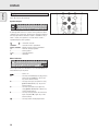
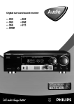
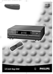
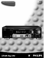
Digital surround sound receiver
FR960
FR970
Important notes for users in the U.K.
Mains plug
This apparatus is fitted with an approved 13 Amp plug.
To change a fuse in this type of plug proceed as follows:
1 Remove fuse cover and fuse.
2 Fix new fuse which should be a
BS1362 5 Amp, A.S.T.A. or BSI approved type.
3 Refit the fuse cover.
If the fitted plug is not suitable for your socket outlets, it
should be cut off and an appropriate plug fitted in its place.
If the mains plug contains a fuse, this should have a value
of 5 Amp. If a plug without a fuse is used, the fuse at the
distribution board should not be greater than 5 Amp.
Note: The severed plug must be disposed of to avoid a
possible shock hazard should it be inserted into a 13 Amp
socket elsewhere.
How to connect a plug
The wires in the mains lead are coloured with the following
code: blue = neutral (N), brown = live (L).
As these colours may not correspond with the colour
markings identifying the terminals in your plug, proceed as
follows:
• Connect the blue wire to the terminal marked N or
coloured black.
• Connect the brown wire to the terminal marked L or
coloured red.
• Do not connect either wire to the earth terminal in the
plug, marked E (or e) or coloured green (or green and
yellow).
Before replacing the plug cover, make certain that the cord
grip is clamped over the sheath of the lead - not simply over
the two wires.
Copyright in the U.K.
Recording and playback of material may require consent.
See Copyright Act 1956 and The Performer’s Protection Acts
1958 to 1972.
2
Italia
DICHIARAZIONE DI CONFORMITA’
Si dichiara che gli apparecchi FR 960 e FR 970 Philips
rispondono alle prescrizioni dell’art. 2 comma 1 del D. M.
28 Agosto 1995 n. 548.
Fatto a Eindhoven, il 01/06/1999
Philips Consumer Electronics
Philips, Glaslaan 2
5616 JB Eindhoven, The Netherlands
Norge
Typeskilt finnes på apparatens bakside.
Observer: Nettbryteren er sekundert innkoplet. Den
innebygde netdelen er derfor ikke frakoplet nettet så lenge
apparatet er tilsluttet nettkontakten.
For å redusere faren for brann eller elektrisk støt, skal
apparatet ikke utsettes for regn eller fuktighet.
English
Français
English ....................................................4
Español
Français.................................................24
Deutsch
Español .................................................44
Nederlands
Deutsch.................................................64
Italiano
Nederlands ...........................................84
Italiano................................................104
3
GENERAL INFORMATION
English
General information
Scope of supply..................................................................................4
Maintenance ......................................................................................4
Setup ..................................................................................................4
Environmental information.................................................................4
Trademark acknowledgment..............................................................4
Controls .................................................................................................5
Remote control
Remote control usage........................................................................6
Remote control buttons .....................................................................7
Programming the universal remote control .......................................8
Connectors............................................................................................9
Connections
Audio connections............................................................................10
Digital audio connections ................................................................10
System control bus, CINEMA LINK .................................................11
Video connections............................................................................11
Mains ...............................................................................................12
Speaker connections........................................................................12
TV as the center speaker .................................................................12
Antenna connections .......................................................................12
System setup
Positioning of the speakers .............................................................13
Speaker setup and testing...............................................................13
Power handling ................................................................................13
Headphones .....................................................................................13
Scope of supply
This receiver is supplied including:
– an universal remote control
– 2 batteries for the remote control, size AA
– a system bus cable for the CINEMA LINK connection
– a loop antenna
– a wire antenna
– this instruction booklet
Maintenance
Clean the receiver with a soft,
slightly dampened, lint-free cloth. Do
not use any cleaning agents as they
may have a corrosive effect.
Do not expose the receiver to
humidity, rain, sand or excessive heat
(caused by heating equipment or
direct sunlight).
Display.................................................................................................14
Setup
Menus
Receiver menu..................................................................................15
TV menu ...........................................................................................16
If you have stacked the components of your system, the
receiver must be on top. Place the receiver on a flat, hard,
stabile surface. Do not cover any vents and leave 50 cm
above and 10 cm left and right of the receiver free for
ventilation.
Source selection
SOURCE SELECTOR..........................................................................17
Reassigning a source selection .......................................................17
Using one source selection for two or more appliances ................17
Playback, recording
Playing a source ...............................................................................18
Adjusting the sound .........................................................................18
Recording from a source..................................................................18
Recording from the digital output ...................................................18
For good reception the loop antenna should not be placed on
top of or beneath VCRs, CD recorders, DVD players, TVs and
other radiation sources.
Surround sound
About surround sound......................................................................19
Switching surround sound ...............................................................19
Surround sound settings..................................................................19
Environmental information
Tuner
Tuning to radio stations ...................................................................20
Switching FM sensitivity .................................................................20
Storing radio stations ......................................................................20
Tuning to stored radio stations........................................................21
Resorting stored radio stations .......................................................21
Naming radio stations .....................................................................21
Clearing station names....................................................................21
RDS R..............................................................................................22
RDS News and Traffic Announcement ............................................22
Technical data
Receiver............................................................................................22
Troubleshooting
Warning............................................................................................23
Troubleshooting................................................................................23
All redundant packing material has been omitted. We have
done our utmost to make the packaging easily separable into
three mono materials: cardboard (box), polystyrene foam
(buffer) and polyethylene (bags, protective foam sheet).
Your set consists of materials which can be recycled if
disassembled by a specialized company. Please observe the
local regulations regarding the disposal of packing materials,
exhausted batteries and old equipment.
Trademark acknowledgment
Manufactured under license from Dolby Laboratories.
“DOLBY”, “DOLBY DIGITAL”, “PRO LOGIC” and the double-D
symbol 2 are trademarks of Dolby Laboratories. Confidential
unpublished works. © 1992–1997 Dolby Laboratories. All
rights reserved.
This set complies with the radio interference
requirements of the European Community.
4
CONTROLS
2 3 4 5 6
7
English
1
VOLUME
SOURCE
SELECTO
R
DVD
PHONO
DIG
LINK
CINEMA
POWER /
UN D
EM A SO
ITA L CIN
TUNER
CE NT ER
CD
HALL
8
ROUND
3D SUR
CDR /
TAPE
Y
STANDB
AV
TV
VCR
TUNER
PRESET
MENU TOR
NAVIGA
SAT
PREV. /
TUNER
PHONES
FRONT
ND
ON/OFF
SURR.
AM/FM
3D
MODE
ND
SURROU
RADIO
TEXT
NEWS
LOUDNE
TER / OK
0
MENU
T/A
SING
PROCES
L SOUND
RE
DIGITA
DU ET
9
SS
EXIT
SENS.
SETUP
SURROU
TREBLE
BASS
NEXT
CO
!
ME
AV / GA
≤ £ ™ ¡)( * & ^ % $
1 POWER / STANDBY.......Switches the receiver on and off.
2 CINEMA LINK ................Switches the system control bus
between the receiver and the TV
on and off.
3 ..........................................Sensor for the infrared remote
control.
4 3D SURROUND ..............Control light for virtual 3D
surround.
5 HALL ................................Control light for HALL.
6 ..........................................Display
7 SOURCE SELECTOR ......Selects the different audio and
video connectors.
8 VOLUME..........................Increases and decreases the
volume level.
9 FRONT AV.......................Selects the FRONT AV / GAME
input (FR 970 only).
0 TREBLE............................Adjusts the treble when used in
combination with VOLUME.
! BASS ...............................Adjusts the bass when used in
combination with VOLUME.
@ LOUDNESS .....................Switches LOUDNESS on and off.
# NEXT 2 ...........................TUNER: searches radio stations.
MENU: switches to the next
menu level.
$ ENTER / OK.....................Confirms selected menu values.
#
@
% TUNER PRESET X MENU NAVIGATOR
TUNER: switches to the next and
previous stored radio station.
MENU: moves upwards and
downwards.
^ 1 PREV. / EXIT ...............TUNER: searches radio stations.
MENU: switches to the previous
menu level.
& SETUP MENU ................Switches the menu on and off.
* SENS. ..............................Switches between low and high
tuner sensitivity.
( NEWS/TA........................Switches the RDS news and
RDS traffic announcement on
and off.
) TUNER AM/FM ..............Switches the wavebands of the
tuner.
¡ RADIO TEXT ...................Scrolls through the different RDS
information.
™ SURR. MODE..................Switches through the different
surround effects.
£ 3D SURROUND ..............Switches virtual 3D surround on
and off.
≤ SURROUND ON/OFF .....Switches the surround sound on
and off.
5
REMOTE CONTROL
English
Remote control usage
Open the battery compartment
of the remote control and insert
2 alkaline batteries, type AA
(R06, UM-3).
Remove batteries if they are flat
or the remote control is not going
to be used for a long time.
MUTE
PHONO
TUNER
CD
CDR/TAPE
TV
VCR
SAT
DVD
Batteries contain chemical substances, so they should
be disposed of properly.
The buttons on the remote control work the same way as the
corresponding ones on the receiver.
Important!
You have to press a source button for longer than 2 seconds
to switch the sound source on the receiver. Pressing a source
button for less than 2 seconds will only switch the remote
control to use the commands for the selected product.
2
H
1
2
3
4
5
6
7
8
9
CINEMA LINK
CABLE BOX
0
GUIDE
The remote control remains tuned to the selected source until
another source button on the remote control is pressed. This
enables you to operate additional sources (i. e. winding a
tape) without changing the source on the receiver.
OK
MENU
É
A
ATV
NEWS/TA
Ç
CHANNEL/TRACK LOUDNESS SOUND
±
í
ë
REC
CANCEL
FR.D.
INDEX
Å
T-C
3D SURR.
SURR.
AUDIO
DVD
NIGHT
ON/
OFF
DISC
REAR
+
SUB WOOFER
-
TEST TONE
CHANNEL
6
SURR. MODE
+
Remote control buttons
H MUTE .....................Mutes the sound of the receiver.
2 ................................Switches the receiver to standby.
PHONO, TUNER, CD,
CDR/TAPE, TV,
VCR, SAT, DVD..............Switches the remote control to the
commands of the different products.
Selects the sources if pressed longer
than 2 seconds. SAT only works with
digital satellite receivers.
1–0................................Keys in numbers for tracks, stations or
frequencies. Numbers consisting of
two figures must be keyed in within
2 seconds.
CINEMA LINK...............Switches the system connection
between the receiver and the TV on
and off.
CABLE BOX ...................Without function.
MENU GUIDE ..............TUNER: Switches the receiver menu
on and off.
DVD, TV: Switches the DVD/TV menu
on and off.
OK .................................Confirms menu options.
Arrow buttons ..............TUNER: Moves in the menus.
Right/left arrows are tuning up/down.
CD, CDR: Left/right arrows are
searching backwards/forwards,
up/down arrows are selecting the
next/previous track.
+A ...........................Increases the receiver volume.
-A ...........................Decreases the receiver volume.
NEWS/TA.................Switches the functions NEWS and
TRAFFIC ANNOUNCEMENT on and off.
TV: Switches teletext on and off.
SAT: Switches the information text on
and off.
ÉATV ......................Increases the TV volume.
CD, CDR, VCR, DVD: Starts playback.
ÇATV ......................Decreases the TV volume.
CD, CDR, VCR, DVD: Stops playback.
í CHANNEL/TRACK ...Selects the previous preset tuner
station.
VCR: Rewinds the tape.
CD, CDR, DVD: Selects the previous
track.
TV: Selects the previous channel.
ë CHANNEL/TRACK ...Selects the next preset tuner station.
VCR: Fast forwards the tape.
CD, CDR, DVD: Selects the next track.
TV: Selects the next channel.
i
LOUDNESS ...................Switches LOUDNESS on and off.
±SOUND....................Scrolls through the different smart
sounds.
REC, DVD AUDIO..........CDR, VCR: Starts recording.
DVD: Switches audio tracks.
CANCEL, DVD ...........CD, CDR, SAT, VCR: Clears a
program, cancels selections.
DVD: Switches the view angle.
FR.D., DVD Å .............TUNER: Switches to FREQUENCY
DIRECT.
CD, CDR, VCR, DVD: Pauses playback.
INDEX, DVD T-C............VCR: Switches the index search on
and off.
SAT: Switches the themes on and off.
DVD: Switches between title and
chapter.
DISC..............................CD-, CDR-, DVD-Changers:
Switches to the next disc.
NIGHT ...........................Switches NIGHT MODE on and off.
3D SURR.......................Switches virtual 3D surround on and off.
SURR. ON/OFF..............Switches SURROUND SOUND on and off.
+/- SUBWOOFER...Increases/decreases the subwoofer
volume.
+/- REAR ...............Increases/decreases the volume of the
rear speakers. While test tone is on,
the volume of the speakers you are
hearing can be increased/decreased
with these buttons.
SURR. MODE................Scrolls through the different surround
modes.
TEST TONE ...................Switches the test tone on and off.
While test tone is on, the volume of
the speakers you are hearing can be
increased/decreased with
+/- REAR.
7
English
REMOTE CONTROL
REMOTE CONTROL
English
Programming the universal remote control
You can identify the universal remote control by the
inscription Multibrand/Universal.
The universal remote control must be programmed to use the
codes for your appliances of different brands. This is done by
keying in a 4-digit code or by scanning the codes until the
correct one is found. We recommend to using the 4-digit
code. This method is faster and more reliable. The code
scanning method should only be used if you cannot find the
code for one of your appliances. The code table can be found
at the end of the booklet.
Once you have found and tested the codes for your various
appliances, you may want to write them down here.
PHONO ..........................................
TUNER...........................................
CD .................................................
CDR/TAPE .....................................
TV ..................................................
Important!
VCR ...............................................
The buttons of the remote control must be used for
programming, not the buttons of the receiver or other
appliances.
SAT................................................
DVD ...............................................
Programming with the 4-digit code
1 Keep the source button for the appliance which should be
controlled and2 pressed for 3 seconds.
2 Key in the 4-digit code for the appliance (codetable at the
end of the booklet).
Notes: – If more than 4 digits are entered, the remote
control will recognize only the ones keyed in first.
– If you do not key in a code within 30 seconds the
remote control will switch off the programming
function without changing the code.
– To program a new appliance, simply overwrite the
old code by entering a new one.
Scanning the codetable
1 Switch on the appliance which should be controlled.
2 Keep the source button for the appliance which should be
controlled and2 pressed for 3 seconds.
3 Press and release 2 again.
y The remote control sends the codes for channel up or
standby (depending on the selected source) for one
brand after the other.
4 As soon as the appliance reacts – switches to the next
channel or to standby – press 2 to confirm the code.
y The identified code will be used.
• If the set does not react within 2 minutes, the code for this
appliance is not stored in the remote control. The code of
the remote control will remain unchanged.
Note: When taking out the batteries of the remote control for
more than 1 minute the codes must be reprogrammed.
8
Resetting the remote control
1 Keep one of the source buttons and 2 pressed for 3
seconds.
2 Key in the 3-digit code 981.
y The remote control is now reset to all its original Philips
codes.
CONNECTORS
ª
º
~ 50 Hz
FM 75 Ω
CINEMA
LINK
.
PHONO GND
(
AM LOO
VIDE
IN
FER
SUBWOO
PRE-OUT
O IN/OUT
CENTER
SAT
OUT
IN
COAX 1 IN
OUT
REC
IN
PLAY
UT
AUDIO IN/O SAT
E
CDR/TAP
ND
SURROU S
SPEAKER
CENTER
T
PRE-OU
CD
VCR
PHONO
TV
R
COAX 2 IN
EACH
L
COAX OUT
R
IN
IN
IN
PLAY
OUT
REC
IN
IN
IN
PLAY
SURROUND SPEAKERS
AUDIO IN/OUT
DIGITAL AUDIO IN/OUT
VIDEO IN/OUT
Antenna connectors
Preamplified outputs
System control bus
Mains outlets
(not on all versions)
Mains lead
ON
C ELE
DE CHO
RISQUENE PAS OUVRIR
in the
Philips
ped by
develo
ed and
Design an Community
m Dolby.
ion
nce fro
Europe
er lice Co rpo rat the
und
d
and of
enc ing
acture
Manuf tor ies Lic "PR O-L OG IC"
arks
dem
,
ora
-3"
Lab
are Tra poration.
", "AC bol
ing Cor
"DO LBY
Licenc
e-D Sym
Doubl Laboratories
Dolby
L
SPEAKE
SURROUND
100W
TOTAL
PHONES
CHED
MAX. SWIT
FRONT
ON/OFF
E
AV / GAM
R≥6Ω
OUT
REC
$#@!09876 5
Connectors
6.3 mm headphone socket
at the front
Audio and video inputs
at the front (FR 970 only)
FRONT SPEAKERS
LINK
AV IS
VCR
MON
DVD
CINEMA
STANDBY
POWER /
K
IC SHOC
ELECTR
RISK OF NOT OPEN
E
DO
CTRIQU
L
R
IN
*
&
^
%
CA U TI
P
DIGITAL
AUDIO
IN/OUT
OPTICAL
LET 230V
AC OUT
FRONT RS
SPEAKE
Ω
KER ≥ 6
EACH SPEA
ANTENNA
English
)¡™£≤∞ §≥•
Connectors name
1 PHONES
43
2
1
Connect to:
A headphone with a 6.3 mm plug.
2 FRONT AV / GAME
Audio and video out sockets of appliances such as video cameras
and game consoles.
3 R, L
Right and left front speaker.
4 CENTER
Center speaker.
5 R, L
Right and left surround speaker.
7 CDR/TAPE OUT
Input of a CD recorder or a tape deck.
8 CDR/TAPE IN
Output of a CD recorder or a tape deck.
9 CD IN
Output of a CD player.
0 SAT IN
Output of a satellite system.
! VCR OUT
Input of a video recorder.
@ VCR IN
Output of a video recorder.
# TV IN
Output of a TV.
$ PHONO IN
Output of a turntable with MM coil.
( PHONO GND f
Ground cable of a turntable.
% COAX OUT
Coaxial input of digital appliances such as CD recorders or MD
recorders.
^ COAX 2 IN
Coaxial output of digital appliances.
& COAX 1 IN
Coaxial output of digital appliances.
* OPTICAL IN
Optical output of digital appliances such as DVD players, CD players,
CD recorders or MD players.
) DVD IN
Output of a DVD player.
¡ MON OUT
Input of a monitor (e. g. the TV).
£ VCR IN
Output of a video recorder.
≤ VCR OUT
Input of a video recorder (for recording).
§ SAT IN
Output of a satellite system.
™ AM LOOP
Frame antenna supplied.
∞ FM 75 Ω
Wire antenna supplied or exterior antenna.
6 CENTER PRE-OUT
Input of a TV when it is used as the centre speaker (only possible
when the CINEMA LINK system bus is connected).
≥ SUBWOOFER PRE-OUT Input of a powered subwoofer.
• CINEMA LINK
System control bus sockets of a Philips TV with CINEMA LINK.
ª AC OUTLET
Supplies same voltage as mains. Up to 100 W total permitted load.
º
After all other connections have been made, connect the
mains lead to the wall socket.
9
CONNECTIONS
English
Audio connections
There are analogue and digital connectors available on some
appliances. If possible use the digital connection; usually this
will result in better sound quality. See “Reassigning a source
selection” on how to use the digital connectors of the
receiver.
Because of a different kind of output signal, the use of Dolby
Digital Laserdisc requires an optional AC-3 RF demodulator.
POWERED
SUBWOOFER
MONITOR / TV
AUDIO
OUT
ANTENNA
FM 75 Ω
PHONO GND.
AM LOOP
FRONT
SPEAKERS
DIGITAL
AUDIO
IN/OUT
EACH SPEAKER ≥ 6 Ω
CINEMA
LINK
OPTICAL IN
SUBWOOFER
VIDEO IN/OUT
DVD
MON
IN
OUT
PHONO
TV
VCR
SAT
VCR
AUDIO IN/OUT
SAT
PRE-OUT
CENTER
COAX 1 IN
COAX 2 IN
IN
PLAY
CAUTION
L
R
RISK OF ELECTRIC SHOCK
DO NOT OPEN
IN
OUT
REC
CD
CENTER
PRE-OUT
CDR/TAPE
AVIS
SURROUND
SPEAKERS
L
RISQUE DE CHOC ELECTRIQUE
NE PAS OUVRIR
Designed and developed by Philips in the
European Community
COAX OUT
Manufactured under licence from Dolby
Laboratories Licencing Corporation.
"DOLBY", "AC-3", "PRO-LOGIC" and the
Double-D Symbol
are Trademarks of
Dolby Laboratories Licencing Corporation.
R
IN
IN
IN
PLAY
IN
OUT
REC
IN
PLAY
IN
R
OUT
REC
L
EACH SPEAKER ≥ 6 Ω
TURNTABLE
CD RECORDER
IN
OUT
VCR
AUDIO OUT
CD PLAYER
AUDIO IN
SAT RECEIVER
Digital audio connections
DVD PLAYER
ANTENNA
FM 75 Ω
PHONO GND.
AM LOOP
FRONT
SPEAKERS
DIGITAL
AUDIO
IN/OUT
CD PLAYER
EACH SPEAKER ≥ 6 Ω
CINEMA
LINK
OPTICAL IN
SUBWOOFER
VIDEO IN/OUT
DVD
MON
IN
OUT
PHONO
TV
VCR
SAT
VCR
AUDIO IN/OUT
SAT
PRE-OUT
CENTER
COAX 1 IN
COAX 2 IN
IN
PLAY
OUT
REC
CAUTION
L
R
RISK OF ELECTRIC SHOCK
DO NOT OPEN
IN
CD
CDR/TAPE
CENTER
PRE-OUT
SURROUND
SPEAKERS
L
R
IN
10
RISQUE DE CHOC ELECTRIQUE
NE PAS OUVRIR
Designed and developed by Philips in the
European Community
COAX OUT
CD RECORDER
AVIS
IN
IN
PLAY
OUT
REC
IN
IN
IN
PLAY
OUT
REC
R
L
EACH SPEAKER ≥ 6 Ω
Manufactured under licence from Dolby
Laboratories Licencing Corporation.
"DOLBY", "AC-3", "PRO-LOGIC" and the
Double-D Symbol
are Trademarks of
Dolby Laboratories Licencing Corporation.
System control bus, CINEMA LINK
If the receiver and your Philips TV (or even better in addition
a Philips VCR or DVD player) are connected with the CINEMA
LINK system bus control, some extra system benefits are
offered:
– Upon starting a source the system will automatically
switch to that input.
– You may control the system via the TV screen. Depending
on the language of the TV, this can be done in your
preferred language.
– The TV can function as the center speaker of your system,
making a separate center speaker unnecessary.
– By pressing the standby button, you can switch the
complete Home Theater System to standby.
TV
EXT 1
EXT 2
EXT 3
TV
AUX
DVD PLAYER
DIGITAL
OUT
ANTENNA
FM 75 Ω
PHONO GND.
AM LOOP
FRONT
SPEAKERS
DIGITAL
AUDIO
IN/OUT
VCR
EACH SPEAKER ≥ 6 Ω
CINEMA
LINK
OPTICAL IN
SUBWOOFER
VIDEO IN/OUT
DVD
MON
IN
OUT
VCR
PRE-OUT
SAT
CENTER
COAX 1 IN
COAX 2 IN
PHONO
IN
PLAY
TV
CAUTION
L
R
RISK OF ELECTRIC SHOCK
DO NOT OPEN
IN
OUT
REC
AUDIO IN/OUT
VCR
SAT
CD
CENTER
PRE-OUT
CDR/TAPE
AVIS
SURROUND
SPEAKERS
L
RISQUE DE CHOC ELECTRIQUE
NE PAS OUVRIR
Designed and developed by Philips in the
European Community
COAX OUT
Manufactured under licence from Dolby
Laboratories Licencing Corporation.
"DOLBY", "AC-3", "PRO-LOGIC" and the
Double-D Symbol
are Trademarks of
Dolby Laboratories Licencing Corporation.
R
IN
IN
IN
PLAY
IN
OUT
REC
IN
PLAY
IN
R
OUT
REC
L
EACH SPEAKER ≥ 6 Ω
CINEMA LINK
TO TV IN
TO VCR IN
Video connections
MONITOR / TV
DVD PLAYER
ANTENNA
FM 75 Ω
AM LOOP
FRONT
SPEAKERS
DIGITAL
AUDIO
IN/OUT
EACH SPEAKER ≥ 6 Ω
CINEMA
LINK
OPTICAL IN
SUBWOOFER
VIDEO IN/OUT
DVD
MON
IN
OUT
VCR
PRE-OUT
SAT
CENTER
COAX 1 IN
COAX 2 IN
PHONO
IN
PLAY
OUT
REC
TV
CAUTION
L
R
RISK OF ELECTRIC SHOCK
DO NOT OPEN
IN
AUDIO IN/OUT
VCR
SAT
CD
CDR/TAPE
CENTER
PRE-OUT
SURROUND
SPEAKERS
L
AVIS
RISQUE DE CHOC ELECTRIQUE
NE PAS OUVRIR
Designed and developed by Philips in the
European Community
COAX OUT
R
IN
IN
IN
PLAY
OUT
REC
IN
IN
IN
PLAY
OUT
REC
R
L
EACH SPEAKER ≥ 6 Ω
Manufactured under licence from Dolby
Laboratories Licencing Corporation.
"DOLBY", "AC-3", "PRO-LOGIC" and the
Double-D Symbol
are Trademarks of
Dolby Laboratories Licencing Corporation.
VCR
VIDEO OUT
VIDEO IN
SAT RECEIVER
11
English
CONNECTIONS
CONNECTIONS
English
Mains
Antenna connections
The type plate is located on the rear of the receiver.
AM (MW) antenna
The loop antenna supplied is for indoor use only. Position the
antenna as far away as possible from the receiver, the TV, the
cables, a DVD player, a VCR and other radiation sources.
1 Check whether the mains voltage as shown on the type
plate corresponds to your local mains voltage. If it does not,
consult your dealer or service organization.
1 Fit the plug of the frame antenna to AM LOOP as shown
below.
2 Connect the mains cable to the wall socket.
To disconnect the set from the mains completely, remove the
mains plug from the wall socket.
2 Turn the antenna for optimum reception.
A
For users in the U. K.: please follow the instructions on
page 2.
Speaker connections
ANTENN
P
AM LOO
Some of the speaker connections on the receiver are screw
connectors and some are click-fit connectors. Use them as
shown below.
7m
m
FM antenna
The wire antenna supplied can only be used to receive nearby
stations. For better reception we recommend using a cable
antenna system or an outdoor antenna.
1 Fit the supplied wire antenna to FM 75 Ω as shown below.
1
2
3
2 Move the antenna in different positions for optimum
reception.
• If you are using a cable antenna system or an outdoor
antenna, fit the antenna plug to FM 75 Ω instead of the
wire antenna.
m
8m
1
2
3
FM 75 Ω
1 Always connect the coloured (or marked) wire to the
coloured terminal and the black (or unmarked) wire to the
black terminal.
2 Connect:
– Left front speaker to L (red and black)
– Right front speaker to R (red and black)
– Center speaker to CENTER (blue and black)
– Left surround speaker to SURROUND L (grey and black)
– Right surround speaker to SURROUND R (grey and black)
TV as the center speaker
You may use your Philips TV with CINEMA LINK as the center
speaker. For TVs with a scart connector an additional audio
cinch-to-scart cable is needed. For TV’s with cinch connectors
additional cinch cables are needed. These cables must be
connected to the blue CENTER PRE-OUT connector on the
back. Look into the instruction manual of your TV on how to
use it as the center speaker.
12
FM 75 Ω
NT
CENTER
FR
ON
T
SU
BW
OO
FE
R
FRO
LEFT
SURROUND
(REAR)
LEFT
RIGHT
RIGHT
SURROUND
(REAR)
Positioning of the speakers
General hints for positioning
Avoid positioning the speakers in a corner or on the floor as
this will boost the bass tones too much. Placing the speakers
behind curtains, furniture, etc. will reduce the treble
response. The listener should always be able to ”see” the
speakers.
Each room has different acoustic characteristics and the
positioning possibilities are often limited. You can find the
best position for your speakers by referring to the picture
above.
As a minimum we recommend 5 speakers (2 front, a center,
2 surround) for good surround sound. It is possible to
reproduce some kind of surround sound with fewer speakers.
This is done by redirecting the signals which are foreseen for
the missing speakers to the existing ones. See “Menus” on
how to set up the receiver correctly for the number and size
of the speakers used.
Positioning the front speakers
The front speakers should be placed right and left in front of
the listening position like usual stereo speakers.
Positioning the center speaker
The center speaker should be placed in the center between
the two front speakers, e. g. underneath or on top of the TV.
The best height for the center speaker is the height of the
listener’s ears (while seated).
Positioning the surround speakers
The surround speakers should face each other and be in line
with, or slightly behind the listener.
Positioning the subwoofer
A subwoofer can be used to enhance the bass performance of
your system dramatically. The subwoofer can be positioned
anywhere in the room, because it is not possible to locate the
source of deep tones. Nevertheless, you should not place the
subwoofer in the middle of a room, since the bass could be
severely weakened. Do not place any object on the
subwoofer.
Speaker setup and testing
The relative volume of the speakers must be adjusted for
optimal surround sound. You should be at your usual listening
position when adjusting the speaker volume. See “Receiver
menus” on how to set up the receiver for the used speakers.
1 Press POWER / STANDBY to switch on the receiver.
2 Press TEST TONE on the remote control.
y A test tone coming from the different speakers, except
the subwoofer, is heard.
3 Press +/- REAR on the remote control to
increase/decrease the volume of the actual speaker. The
best result is achieved when all speakers have equal
volume in the listening position.
4 Press TEST TONE on the remote control.
y The test tone stops.
Note: If you are not completely satisfied with the volume
settings, we recommend making minor adjustments to
them during surround sound playback.
Power handling
If the receiver is used at very high power it can produce
distortions which may seriously damage your speakers. If
distortions occur, reduce the volume and the tone controls to
a level where the sound is acceptable again.
To avoid overheating of the set a safety circuit has
been built in. Therefore your set may disconnect under
extreme conditions. If this happens, switch the set off
and let it cool down before reusing it.
Headphones
Connecting headphones to PHONES will switch off the
speakers. The receiver switches to STEREO and surround
sound will be reduced to a stereo signal which is reproducible
by standard headphones.
Disconnecting the headphones switches on the speakers
again. If you wish to enjoy surround sound again, switch the
receiver back to surround sound.
13
English
SYSTEM SETUP
DISPLAY
English
0
Display
The display of the receiver is divided into 4 sections, which
are to be used for the following:
GUIDE
OK
MENU
Speaker diagram
É
A rectangle with a letter in it shows that a speaker has been
selected in the setup menu. However, the subwoofer indicator
will only light when a subwoofer signal is available. If only a
letter is shown, this speaker is not used and its sound is
reproduced by the other speakers.
.......virtual 3D surround
sound is reproduced
DIGITAL SURROUND ....digital surround sound is reproduced
L, R ...........................front left and right speaker
C ...............................center speaker
SL, SR .......................surround speakers
SW ............................subwoofer
SURROUND.................surround
Menu indication
These signs show you if the menu is on or off and indicate in
which direction you may move.
M E N U .......................menu
is on
1..............................You may move backwards to the previous
menu topic using 1 PREV. / EXIT (“left”
key on the remote control).
3 .............................You may move up in an option list using
X MENU NAVIGATOR (“up” key on the
remote control).
4 .............................You may move down in an option list
using X MENU NAVIGATOR (“down” key
on the remote control).
2..............................You may move forward to the next menu
topic using NEXT 2 (“right” key on the
remote control).
O K.............................You may confirm the displayed value.
14
A
ATV
NEWS/TA
Ç
Receiver menu
The receiver is equipped with a menu system. The menu is
used for the setup of the receiver. The different menu options
are related to each other in a logical way. Let’s assume you
have no center speaker connected, and therefore switched
CENTER SPEAKR to NO. If you try to use VOL CENTER,
a message will be scrolled that this is not possible
(INSTALL CENTER SPEAKER).
The menu always works the same way. Arrows in the display
show you the possible moving directions.
1 Press SETUP MENU.
y MENU, and * EFFECTS is displayed.
• You can exit the menu at any time by pressing
SETUP MENU.
2 Turn X MENU NAVIGATOR until the desired option (or a
value) is displayed.
3 Press NEXT 2 to choose the displayed option (or
ENTER / OK to confirm a value).
• You can leave any option (values remain unchanged) by
pressing 1 PREV. / EXIT.
Menu structure
* EFFECTS
Switches sound effects.
3D SURR
virtual 3D surround: 0…100 %
* VOL BALANCE
Adjusts the relative volume balance between the
connected speakers.
TEST TONE
Test tone: on/off
VOL FRONT-L
Volume front left speaker: –50…+50
VOL FRONT-R
Volume front right speaker: –50…+50
VOL CENTER
Volume center speaker: –50…+50
VOL REAR-L
Volume rear left speaker: –50…+50
VOL REAR-R
Volume rear right speaker: –50…+50
VOL SUBWOOFER
Volume subwoofer: –50…+50
* SPEAKR SETUP
Selects the used speakers.
SUBW PRESENT
Subwoofer present: yes/no
CENTER SPEAKR
Center speaker present: yes/no
REAR SPEAKER
Rear speakers present: yes/no
* SPEAKR SIZES
Chooses the speaker sizes of the used speakers, for
optimal sound reproduction. LARGE indicates a speaker
which can reproduce frequencies lower than 50 Hz. If
SUBW PRESENT is set to NO, FRONT SIZE can only
be set to LARGE. If FRONT SIZE is set to SMALL,
CENTER SIZE can only be set to SMALL and
consequently a subwoofer must be connected.
SUBW PRESENT
Subwoofer present: yes/no
FRONT SIZE
Left and right front speakers: small/large
CENTER SIZE
Center speaker: small/large
REAR SIZE
Rear speakers: small/large
* SPK DISTANCE
Distance between the usual listening position and the
speakers. This defines the delay time for the surround sound.
DISTANCE L/ R
Distance to front speakers: 1…10 m
DISTANCE CNTR
Distance to center speaker: 1…10 m
DISTANCE REAR
Distance to rear speakers: 1…10 m
* SELECT INPUT
Assigns the audio input connectors to the different source
selections chosen with SOURCE SELECTOR (see “SOURCE
SELECTION” for details).
COAX1
Digital coaxial input 1, COAX 1 IN
COAX2
Digital coaxial input 2, COAX 2 IN
OPT
Digital optical input, OPTICAL IN
SAT IN
Analogue audio input SAT IN
VCR IN
Analogue audio input VCR IN
TV IN
Analogue audio input TV IN
CDR IN
Analogue audio input CDR IN
CD IN
Analogue audio input CD IN
* TUNER
Setup for preset radio stations (see “TUNER” for details).
AUTO INSTALL
Stores radio stations automatically
MAN INSTALL
Stores radio stations manually
GIVE NAME
Allows to assign names to stored radio stations
RESHUFFLE
Resorts stored radio stations
15
English
MENUS
MENUS
English
TV menu
If the receiver is connected to a Philips CINEMA LINK TV via
the CINEMA LINK system control bus sockets (see
“CONNECTIONS”), you may use the TV to set up the system.
An option called RECEIVER will be added to the TV menu.
If CINEMA LINK is on, adjustments on the receiver will be
shown on the TV screen for a few seconds. Consult the
instruction booklet of your TV on how to use the TV menu.
The options offered may vary by TV model.
Switching the connection
• Press CINEMA LINK to switch the connection between the
receiver and the TV either on or off.
y If the connection is switched on, CINEMA LINK ON is
displayed.
Note: We recommend switching CINEMA LINK off during
recording. This avoids unwanted interruptions due to
switching TV functions.
If CINEMA LINK is switched on and the TV menu is active,
TV MENU is displayed and the menu and sound functions on
the receiver are locked.
16
SOURCE SELECTOR
When selecting a source by turning SOURCE SELECTOR, the
audio and video inputs with the corresponding name are
activated. The incoming signal is reproduced by all audio and
– if the source includes a video signal – video outputs of the
receiver. It is possible to reassign a source selection to other
than these standard inputs.
Source selected........Connectors used
DVD...............................COAX 1 digital audio input and
DVD IN video input
PHONO..........................PHONO IN audio input
TUNER ..........................The tuner part of the receiver is used,
all inputs are switched off.
CD .................................CD IN audio input
CDR/TAPE .....................CDR/TAPE IN audio input
TV..................................TV IN audio input and
no video input
VCR ...............................VCR IN audio input and
VCR IN video input
SAT ...............................SAT IN audio input and
SAT IN video input
Reassigning a source selection
If a source is selected with SOURCE SELECTOR the standard
audio input is used. To change this, the source selection must
be reassigned to another audio input.
Using one source selection for two or more
appliances
You may assign more than one source to a source selection.
This can be useful when products are connected one after the
other in a chain.
Example: A VCR is connected to the TV but only the TV is
connected to the receiver. Both SOURCE SELECTOR
settings, TV as well as VCR, have to use the TV
input connectors.
1 Choose * SELECT INPUT from the menu and press
NEXT 2.
2 Turn SOURCE SELECTOR to select the source which should
be reassigned (e. g. VCR).
y The name of the source is displayed and the light of the
source flashes.
3 Turn X MENU NAVIGATOR to select the input connectors
which should be used (e. g. VCR -> TV IN).
4 Press ENTER / OK to confirm your selection.
y STORED is displayed briefly.
5 This source selection is now using the chosen audio input (e. g.
VCR uses the TV IN input connectors, VCR <TV IN> is
displayed briefly when switching to VCR).
Example: Reassigning CD from the analogue CD IN audio
input to the digital COAX 2 IN audio input.
1 Choose * SELECT INPUT from the menu and press
NEXT 2.
2 Turn SOURCE SELECTOR to select the source which should
be reassigned (e. g. CD).
y The name of the source is displayed and the light of the
source flashes.
3 Turn X MENU NAVIGATOR to select the input connectors
which should be used (e. g. CD -> COAX2).
4 Press ENTER / OK to confirm your selection.
y STORED is displayed briefly.
5 This source selection is now using the chosen audio input
(e. g. CD uses the COAX 2 IN input connectors, COAX 2
lights when switching to CD).
17
English
SOURCE SELECTION
PLAYBACK, RECORDING
English
Playing a source
Recording from a source
1 Press POWER / STANDBY to switch on the receiver.
If you wish to record from a source you must select it with
SOURCE SELECTOR. The incoming signal is reproduced by all
audio and – if the source includes a video signal – video
outputs of the receiver. The sound settings do not affect the
recording.
2 Turn SOURCE SELECTOR to select a source.
y The name of the source is displayed.
• You can select the FRONT AV / GAME input by pressing
FRONT AV (FR 970 only).
3 Start playback of the source as usual.
Adjusting the sound
• Turn VOLUME to adjust the volume.
y VOLUME and the volume level between 0 and 50 is
displayed.
1 Press BASS or TREBLE.
y BASS or TREBLE and the actual value are displayed
briefly. Then TURN VOLUME KNOB TO CHANGE is
scrolled.
2 Turn VOLUME to adjust the bass or treble.
y BASS or TREBLE and the actual value are displayed.
Note : If VOLUME is not turned within 5 seconds or if any
other control is used, the bass or treble adjustment is
switched off.
• Press ±SOUND on the remote control to scroll through
the built-in smart sounds: MOVIE, SPEECH, MUSIC,
MULTIMEDIA and PERSONAL. (PERSONAL is the
userdefined bass and treble setting.)
y SMART SOUND is displayed and the name of the chosen
sound profile is scrolled once if smart sound is on.
• Press LOUDNESS to switch loudness either on or off.
y LOUDNESS is displayed if loudness is on.
1 Turn SOURCE SELECTOR (or press FRONT AV – FR 970 only)
to select the source you want to record from.
y The name of the source is displayed.
2 Prepare the desired recording appliance. It must be
connected to one of the outputs of the receiver.
3 Start recording on the recording appliance.
4 Start the playback of the source as usual.
Notes: – The audio and video signal of VCR IN is not
reproduced by VCR OUT. The same applies to the
audio signal of CDR/TAPE IN to CDR/TAPE OUT.
– We recommend not to use the digital output
COAX OUT of the receiver to record from an
analogue source. Use the analogue output
CDR/TAPE instead.
Recording from the digital output
It is possible to connect a digital recorder to the digital output of
the receiver. In this way, all signals coming from the digital
inputs can be recorded directly on the connected audio recorder.
The receiver will also convert all signals coming from the
analogue inputs to the digital output.
The receiver can be used to record digitally a multichannel
surround sound audio signal (Dolby Digital or MPEG) from, for
example, DVD to CD-R. The receiver will convert the digital
multichannel signal into a stereo signal without loss of relevant
sound information.
Notes: – Do not use the 3D SURROUND feature while making
digital recordings as this will distort the digital
audio signal.
– When recording a Dolby Digital or MPEG signal, each
track must be recorded individually.
18
About surround sound
Surround sound settings
Surround sound gives you a complete new listening
sensation. You will have the feeling of being in the middle of
the action, because sound is coming from everywhere around
you. Look out for TV broadcasts, audio and video tapes and
discs with the 3 1 or
marks which are encoded for multichannel surround sound.
You should prefer Dolby Digital or MPEG Multichannel to get
the best out of your receiver.
HALL
The sound reproduction is enhanced and a slight echo is
added. This gives the impression of being in a large room.
Can only be used in stereo mode.
Notice that DVDs do not always carry full multichannel
surround. To be sure that a disc is multichannel encoded
consult your dealer.
Most ordinary stereo tapes and discs can be replayed using
surround sound settings with good results. If the reproduction
is distorted in surround mode, switch to normal stereo mode.
The availabilty of the various surround sound modes
described depends on the number of speakers used and the
incoming sound information.
Switching surround sound
With surround sound on, you can switch through the different
surround modes. Note that the possibilities are related to
speaker setup defined in the receivers menu.
If a digital surround signal is detected, the receiver will scroll
either DOLBY DIGITAL or MPEG.
1 Press SURROUND ON/OFF to switch on the surround sound.
y The surround mode in use is scrolled.
2 Press SURR. MODE repeatedly to listen to the different
surround modes (if available).
yThe chosen mode and the speakers used are displayed.
If the incoming multichannel signals are reduced to
fewer output signals, DOWNMIX is displayed.
3 Press 3D SURROUND to switch virtual 3D surround either
on or off.
yA light indicates if virtual 3D surround is on.
English
SURROUND SOUND
SURROUND
The surround mode enables normal surround sound reproduction
with 4 or 5 speakers. Depending on the source material, Dolby
Surround Pro Logic, Dolby Digital or MPEG is reproduced.
PRO LOGIC, DOLBY DIGITAL, MPEG
In addition to SURROUND, the surround mode used –
depending on the source material – will be displayed. In case
of digital surround, the sound format AC-3 (for Dolby Digital) or
MPEG (for MPEG 2 Multichannel) will be displayed, followed by
the sound channels, available on the source (e. g. DVD).
Example: AC-3 3/2.1 Dolby Digital, 3 front channels,
2 surround channels and a subwoofer
channel.
MPEG 2/0.0 MPEG Multichannel, stereo sound only.
AC-3 3/1.0 Dolby Digital, 3 front channels, 1
(mono) surround channel without
subwoofer signal.
FRONT-3 STEREO
The surround sound is muted. 3 Stereo lets you listen to
surround sound without using the surround speakers.
3D SURROUND
The sound of the rear channel is simulated by the front
speakers. Surround sound is simulated through the front left,
right and center speakers. The position of the listener
influences the surround effect. The area where the effect is
best is shown in grey.
NT
FRO
LEFT
CENTER
FR
ON
T
RIGHT
4 Press SURROUND ON/OFF to switch off the surround
sound.
y SURROUND OFF is scrolled.
STEREO
All sound is reproduced and played through the front left and
right speakers. This enables standard stereo reproduction.
NIGHT MODE (only on the remote control)
The loud parts of the sound are lowered and the soft
passages are raised. You can enjoy surround sound without
disturbing sleeping children or neighbours. Night mode only
works with Dolby Digital and MPEG, and only if supported by
the source material.
19
TUNER
English
Tuning to radio stations
Storing radio stations
You can search for radio stations by scanning the frequency
band. You can also key in the frequency of a known radio
station. If an FM station is being broadcast and received in
stereo, STEREO is shown.
You may store up to 30 radio stations in the memory. The
receiver can select and program radio stations by itself or you
can choose them yourself.
Searching for radio stations
1 Turn SOURCE SELECTOR to select the tuner.
y TUNER is displayed.
2 Select a waveband by pressing TUNER AM/FM repeatedly.
y The selected waveband is displayed.
3 Keep 1 or 2 pressed for approximately 1 second.
y SEARCH is displayed and the tuner tunes to a station
with sufficient strength.
4 Repeat this procedure until you find the desired station.
Automatic programming
1 Choose * TUNER from the menu and press NEXT 2.
2 Choose AUTO INSTALL and press NEXT 2.
y The preset number where programming will start, the
waveband and AUTO are displayed.
3 Turn TUNER PRESET X to change the preset number where
programming should start.
4 Use TUNER AM/FM to switch to the desired waveband.
• To fine tune to a weak transmitter, briefly press 1 or 2 as
often as necessary for optimum reception.
5 Press ENTER / OK to start programming.
y AUTO INSTALL flashes and all available radio
stations are programmed, this may take a few minutes.
Programming is done when AUTO INSTALL stops
flashing.
Tuning to a radio station by frequency (with the remote
control only)
1 Press TUNER.
y TUNER is displayed.
Manual programming
1 Choose * TUNER from the menu and press NEXT 2.
2 Press FR. D..
y _ is displayed.
3 Use 1–0 to key in the frequency of a radio station.
Note: Only valid numbers within the frequency range of the
tuner can be keyed in.
Switching FM sensitivity
2 Choose MAN INSTALL and press NEXT 2.
y A preset number, the waveband and the frequency are
displayed.
3 Turn TUNER PRESET X to change to the preset number
where the radio station should be stored.
4 Tune to the desired radio station (see “Searching for radio
stations”).
You can switch the tuner to a lower search sensitivity, to
search only for stations with a strong signal (FM only).
5 Press ENTER / OK to confirm your selection.
y STORED is displayed briefly. The radio station is
programmed at the chosen preset number.
1 Turn SOURCE SELECTOR to select the tuner.
y TUNER is displayed.
6 Select and store all desired radio stations this way.
2 Press SENS. on the receiver.
y Either SENS HI or SENS LO is displayed for 5 seconds.
Note: While searching for radio stations, the actual sensitivity
is displayed. In this case, SENS LO means the tuner is
only looking for radio stations with a strong signal.
20
Tuning to stored radio stations
Naming radio stations
1 Turn SOURCE SELECTOR to TUNER to select the tuner.
y TUNER is displayed.
It is possible to assign a name to any of the preset radio
stations. RDS station names also can be overwritten.
2 Turn TUNER PRESET X to select a preset radio station.
y PRESET, the preset number and station are displayed.
1 Choose * TUNER from the menu and press NEXT 2.
Resorting stored radio stations
After programming radio stations, you might want to change
their sequence. RESHUFFLE allows you to exchange the
positions of presets.
1 Choose * TUNER from the menu and press NEXT 2.
2 Choose RESHUFFLE and press NEXT 2.
y PRESET, a preset number and station are displayed.
3 Turn TUNER PRESET X to select a preset station.
4 Press ENTER / OK to confirm the selection.
y The selected preset number SWAP <-> and a second
preset number are displayed.
5 Turn TUNER PRESET X to select the other preset station.
6 Press ENTER / OK to confirm the exchange.
y RESHUFFLED is displayed briefly and these two
preset numbers are swapped.
English
TUNER
2 Choose GIVE NAME and press NEXT 2.
y A preset radio station is displayed.
3 Turn TUNER PRESET X to select the preset to be renamed.
4 Press ENTER / OK to confirm your selection.
yThe existing name or ________ is displayed.
5 Turn TUNER PRESET X to select a letter and NEXT 2 or
1 PREV. to move to the next or previous position.
6 After you have entered the entire name, press ENTER / OK
to confirm.
y STORED is displayed and the name is stored.
Note: If you want to use the transmitted RDS station name
again, simply clear the given name.
Clearing station names
1 Use the menu option * TUNER, choose GIVE NAME.
y A preset radio station is displayed.
2 Turn X MENU NAVIGATOR to select the name to be
cleared.
3 Press ENTER / OK to confirm your selection.
4 Press 1 PREV. while the first letter is flashing.
y CL is flashing to the left of the station name.
5 Press ENTER / OK to clear the station name.
Or, if you have changed your mind,
press 1 PREV. to leave the station name as it is.
21
English
TUNER
TECHNICAL DATA
RDS R
Receiver
Radio Data System is a service that allows FM stations to
send additional information. If you are receiving an RDS
station, R and the station name are displayed.
Subject to modification without notice.
General
Power consumption (FR 960)........................................≈ 170 W
Power consumption (FR 970)........................................≈ 195 W
Standby power consumption ............................................< 2 W
Dimensions, w × h × d ............................435 × 135 × 350 mm
Weight (FR 960) ................................................................8.6 kg
Weight (FR 970) ................................................................9.4 kg
Amplifier part (0.7 % THD, 6 Ω, 1 kHz)
Output power, stereo mode (FR 960) (DIN).................2 × 50 W
Output power, surround mode (FR 960)
Front ......................................................................2 × 50 W
Center ..........................................................................50 W
Surround................................................................2 × 50 W
Output power, stereo mode (FR 970) (DIN)...............2 × 100 W
Output power, surround mode (FR 970)
Front ....................................................................2 × 100 W
Center ........................................................................100 W
Surround................................................................2 × 50 W
Bass ..................................................................±9 dB at 100 Hz
Treble ................................................................±9 dB at 10 kHz
Loudness ....+6 dB at 100 Hz (-30 dB); +3 dB at 10 kHz (-30 dB)
Total harmonic distortion.........................0.05 % at 1 kHz, 1 W
Frequency response ..................................20–30,000 Hz, ±1 dB
S/N ratio ........................................................................≥ 82 dB
Stereo separation (1 kHz) ..............................................≥ 45 dB
Crosstalk (1 kHz) ...........................................................≤ -65 dB
Digital sampling frequency.................32 kHz, 44.1 kHz, 48 kHz
Inputs
Linear inputs ...................................................250 mV at 47 kΩ
Front AV (FR 970 only) ....................................250 mV at 22 kΩ
Phono ..................................................................5 mV at 47 kΩ
Digital coaxial ..............................................75 Ω acc. IEC 958
Outputs
Power supply AC outlets (switched) ...........totally max. 100 W
Linear outputs...................................................250 mV at 1 kΩ
Digital coaxial ..............................................75 Ω acc. IEC 958
Digital optical ..................................................................Toslink
Subwoofer pre-out................................................0.8 V at 1 kΩ
Center pre-out.......................................................0.8 V at 1 kΩ
Headphones....................................8–600 Ω (3 V e.m.f., 60 Ω)
Speakers ...........................................................................≥ 6 Ω
Tuner part
Wave range
FM..............................................................87.5–108.0 MHz
MW...............................................................531–1,602 kHz
LW....................................................................153–279 kHz
Sensitivity
Stereo FM ..................................................................41 dBf
Mono FM....................................................................15 dBf
Total harmonic distortion
Stereo FM ...................................................................0.3 %
Mono FM...................................................................0.85 %
Frequency response ...................................63–12,500 Hz ±1 dB
S/N ratio
Stereo FM....................................................................55 dB
Mono FM.....................................................................60 dB
Channel separation .............................................35 dB at 1 kHz
Switching through different RDS information
• Press RADIO TEXT on the receiver repeatedly to switch
through the following information (if available):
– Radio text messages
– RDS clock
– Frequency
– Station name
Note: The time signal broadcasted from certain RDS stations
may not always be accurate.
RDS News and Traffic Announcement
It is possible to set up the tuner in such a way that any
playback is interrupted by news or traffic information of a
chosen RDS station. Announcement functions only work if the
necessary RDS signals are being broadcast.
If RDS stations are also carrying an EON signal (Enhanced
Other Networks), EON is displayed. This signal enables the
tuner to search not only the chosen RDS station, but the
whole EON station network for news and traffic information.
1 Tune to the desired RDS station.
2 Press NEWS/TA:
Once to display NEWS, this switches on the news
announcement function.
Twice to display TA, this switches on the traffic
announcement function.
Three times to display TA and NEWS, this switches on both
announcement functions.
3 Select and play any other source as usual.
y While news or traffic information is being broadcast
the receiver will switch to tuner and NEWS or TA will
flash.
4 Press NEWS/TA until the display indication disappears to
switch off the function(s).
or
Press NEWS/TA during an announcement to switch off the
function(s).
Note: Be sure to switch the news and traffic announcement
off during recording, otherwise these announcements
also will be recorded.
22
WARNING
Under no circumstances should you try to repair the
set yourself as this will invalidate the guarantee. Do
not open the set as there is a risk of electric shock.
If a fault occurs, first check the points listed, before taking
the set for repair.
If you are unable to solve a problem by following these hints,
consult your dealer or service centre.
PROBLEM
POSSIBLE CAUSE
SOLUTION
No sound
VOLUME is not correctly adjusted.
Adjust the VOLUME.
Headphones are connected.
Disconnect headphones.
The wrong source is selected.
Turn SOURCE SELECTOR to select the correct
source.
One speaker is wrongly connected.
Connect the speaker properly.
A speaker cable is damaged.
Replace the cable.
Volume balance in the receiver menu is
wrongly adjusted.
Adjust VOL FRONT-L and VOL FRONT-R
in the receiver menu.
No sound on the
left or right side
Poor sound or no sound at SURROUND mode is not switched on.
the center or surround
speakers
Surround and/or center speakers are not
(properly) connected.
Press SURROUND ON/OFF to switch on the
surround sound.
Connect the speakers properly.
Surround and/or center speakers are switched Set speaker present to YES.
off in the SPEAKR SETUP menu.
A speaker cable is damaged.
Replace the cable.
Poor bass sound
Speakers are not in phase.
Connect the coloured (or marked) wires to the
coloured terminals and the black (or unmarked)
wires to the black terminals.
Bad sound
Badly matching setting for the given type of
music or sound.
Correct the sound settings on the receiver.
Surround sound level is
too low or too high
The level of the surround sound is not
properly adjusted.
Adjust the level of the surround sound on
the receiver.
Center sound level is too
low or too high
The sound level of the center channel is not
properly adjusted.
Adjust the level of the center channel
on the receiver.
Only center speaker is
heard in Dolby Surround
Pro Logic
A mono signal is reproduced.
Choose a different sound source or switch off
surround sound.
Bad radio reception,
automatic programming
does not work properly
Receiver or antenna is positioned near a
radiation source such as a TV, CD player,
CD recorder, DVD player, etc.
Change the position of the interfering unit
or try to switch it off.
23
English
TROUBLESHOOTING
English
Meet Philips at the Internet
http://www. philips.com
Français
Español
Deutsch
Nederlands
Italiano
W
3104 215 3604.3
FR960
FR970
VieUrs9942