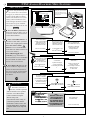
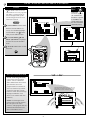
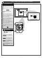
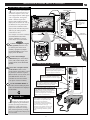
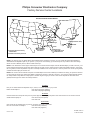
1
Digital Projection Television
64PH9901
Instructions for use
A T S C
C E R T I F I E D
TM
D I G I TA L
T E L E V I S I O N
Return your Warranty Registration card today to ensure you receive
all the benefits you’re entitled to.
Once your PHILIPS purchase is registered, you’re eligible to receive all the privileges of owning a
PHILIPS product. So complete and return the Warranty Registration Card enclosed with your
purchase at once. And take advantage of these important benefits.
Warranty
Verification
Owner
Confirmation
Model
Registration
Registering your product within
10 days confirms your right to
maximum protection under the
terms and conditions of your
PHILIPS warranty.
Your completed Warranty
Registration Card serves as
verification of ownership in the
event of product theft or loss.
Returning your Warranty
Registration Card right away
guarantees you’ll receive all
the information and special
offers which you qualify for as the
owner of your model.
ON N
E
S
Congratulations on your purchase,
and welcome to the “family!”
ED WITH
H
ur
ry
!
REGISTR
TI
ED
A
IN
10 DA
Y
Dear PHILIPS product owner:
Thank you for your confidence in PHILIPS. You’ve selected one of the best-built, best-backed
products available today. And we’ll do everything in our power to keep you happy with your purchase
for many years to come.
As a member of the PHILIPS “family,” you’re entitled to protection by one of the most comprehensive
warranties and outstanding service networks in the industry.
What’s more, your purchase guarantees you’ll receive all the information and special offers for which
you qualify, plus easy access to accessories from our convenient home shopping network.
And most importantly you can count on our uncompromising commitment to your total satisfaction.
All of this is our way of saying welcome–and thanks for investing in a PHILIPS product.
Sincerely,
P.S. Remember, to get the most from your PHILIPS
product, you must return your Warranty
Registration Card within 10 days. So please mail it
to us right now!
Robert Minkhorst
President and Chief Executive Officer
Know these
safetysymbols
CAUTION
RISK OF ELECTRIC SHOCK
DO NOT OPEN
CAUTION: TO REDUCE THE RISK OF ELECTRIC SHOCK, DO NOT
REMOVE COVER (OR BACK). NO USER-SERVICEABLE PARTS
INSIDE. REFER SERVICING TO QUALIFIED SERVICE PERSONNEL.
t
This “bolt of lightning” indicates uninsulated material within your unit which may cause an
electrical shock. For the safety of everyone in your household, please do not remove product
covering.
s
The “exclamation point” calls attention to features for which you should read the enclosed
literature closely to prevent operating and maintenance problems.
WARNING: TO PREVENT FIRE OR SHOCK HAZARD, DO NOT EXPOSE THIS EQUIPMENT
TO RAIN OR MOISTURE.
CAUTION: To prevent electric shock, match wide blade of plug to wide slot, and fully insert.
ATTENTION: Pour éviter les chocs électriques, introduire la lame la plus large de la fiche dans la
borne correspondante de la prise et pousser jusqu’au fond.
INTERNET ADDRESS: http://www.philipsusa.com
2
SAFETY INSTRUCTIONS - Read before operating equipment
This product was designed and manufactured to meet strict quality and
safety standards. There are, however, some installation and operation
precautions which you should be particularly aware of.
1.
Read Instructions - All the safety and operating instructions should
be read before the appliance is operated.
2. Retain Instructions - The safety and operating instructions should
be retained for future reference.
3. Heed Warnings - All warnings on the appliance and in the operating
instructions should be adhered to.
4. Follow Instructions - All operating and use instructions should be
followed.
5. Water and Moisture - The appliance should not be used near water
- for example, near a bathtub, washbowl, kitchen sink, laundry tub,
in a wet basement or near a swimming pool, etc.
6. Carts and Stands - The appliance should be used only with a cart or
stand that is recommended by the manufacturer.
6A.
An appliance and cart combination should be moved
with care. Quick stops, excessive force, and uneven
surfaces may cause the appliance and cart combination
to overturn.
6B. Tilt/Stability - All televisions must comply with recommended
international global safety standards for tilt and stability properties
of its cabinet design.
•
Do not compromise these design standards by applying excessive pull force to the front, or top, of the cabinet which could
ultimately overturn the product.
•
Also, do not endanger yourself, or children, by placing electronic equipment/toys on the top of the cabinet. Such items
could unsuspectingly fall from the top of the set and cause
product damage and/or personal injury.
7. Wall or Ceiling Mounting - The appliance should be mounted to a
wall or ceiling only as recommended by the manufacturer.
8. Ventilation - The appliance should be situated so that its location or
position does not interfere with its proper ventilation. For example,
the appliance should not be situated on a bed, sofa, rug, or similar
surface that may block the ventilation openings; or, placed in a
built-in installation, such as a bookcase or cabinet that may impede
the flow of air through the ventilation openings.
9. Heat - The appliance should be situated away from heat sources
such as radiators, heat registers, stoves, or other appliances
(including amplifiers) that produce heat.
10. Power Sources - The appliance should be connected to a power
supply only of the type described in the operating instructions or as
marked on the appliance.
11. Power-Cord Protection - Power supply cords should be routed so
that they are not likely to be walked on or pinched by items placed
upon or against them, paying particular attention to cords and
plugs, convenience receptacles, and the point where they exit from
the appliance.
12. Cleaning - The appliance should be cleaned only as recommended
by the manufacturer.
13. Power Lines - An outdoor antenna should be located away from
power lines.
14. Outdoor Antenna Grounding - If an outside antenna is connected to
the receiver, be sure the antenna system is grounded so as to
provide some protection against voltage surges and built up static
charges.
Section 810 of the National Electric Code, ANSI/NFPA No. 70-1984,
provides information with respect to proper grounding of the mats
and supporting structure grounding of the lead-in wire to an
antenna discharge unit, size of grounding connectors, location of
antenna-discharge unit, connection to grounding electrodes and
requirements for the grounding electrode. See Fig. below.
15. Non-use Periods - The power cord of the appliance should be
unplugged from the outlet when left unused for a long period of
time.
16. Object and Liquid Entry - Care should be taken so that objects do
not fall and liquids are not spilled into the enclosure through
openings.
17. Damage Requiring Service - The appliance should be serviced by
qualified service personnel when:
A. The power supply cord or the plug has been damaged; or
B. Objects have fallen, or liquid has been spilled into the
appliance; or
C. The appliance has been exposed to rain; or
D. The appliance does not appear to operate normally or exhibits
a marked change in performance; or
E. The appliance has been dropped, or the enclosure damaged.
18. Servicing - The user should not attempt to service the appliance
beyond that described in the operating instructions. All other
servicing should be referred to qualified service personnel.
Note to the CATV system installer: This reminder is provided to call the
CATV system installer's attention to Article 820-40 of the NEC that
provides guidelines for proper grounding and, in particular, specifies that
the cable ground shall be connected to the grounding system of the
building, as close to the point of cable entry as practical.
EXAMPLE OF ANTENNA GROUNDING AS PER NATIONAL ELECTRICAL CODE (NEC)
Example of Antenna Grounding
as per NEC - National Electric Code
GROUND CLAMP
ANTENNA LEAD IN WIRE
ANTENNA DISCHARGE UNIT (NEC SECTION 810-20)
GROUNDING CONDUCTORS (NEC SECTION 810-21)
GROUND CLAMPS
POWER SERVICE GROUNDING ELECTRODE SYSTEM (NEC ART 250, PART H)
ELECTRIC SERVICE EQUIPMENT
3
TABLE OF CONTENTS
11
12
1
2
10
Getting Started
DTV Main Menu
Picture
Sound
Speakers
Features
DTV Setup
Exit
ATSC Digital On-Screen Menu Features
3
9
4
8
7
6
5
Welcome/Product Registration ...................2
DTV SETUP
Safety/Precautions .....................................................3
✧Automatic Programming of area Digital
(over-the-air) Broadcast Channels ...................29
Table of Contents.......................................................4
Features, Model and Cabinet Information .................5
PICTURE MENU
✧Adjusting Color, Brightness, Sharpness,
Tint, and Picture Controls .................................30
MAIN MENU
PICTURE
SOUND
FEATURES
1ST TIME SETUP
EXIT
NTSC Analog On-Screen Menu Features
✧Adjusting DTV Convergence............................31
FIRST TIME SETUP
SOUND MENU
✧Automatic Programming of local NTSC
Channels and other Control Features .................6
✧Surround Sound Speaker Connections..............32
✧Selecting the DPTV Surround Mode Control...33
PICTURE MENU
✧Dolby Digital Internal and External Speaker
System Use and Connections ......................33-34
✧Adjusting Color, Brightness, Sharpness,
Tint, and Picture Controls ...................................7
✧Adjusting Bass and Treble Sound Controls ......35
✧Using the Clearview Control...............................8
✧Using the Auto Volume Control .......................35
✧Adjusting the DPTV's Convergence Control ......9
SPEAKERS MENU
FEATURES MENU
✧Adjusting Speaker Menu Controls for
Front/Center/Rear multi-speaker arrangements36
✧Setting the Smart Picture Controls ..............10-11
✧Setting the DPTV for Closed Captioning..........12
✧Using the Test Tone Audio Signal Control.......37
✧Setting the DPTV for Cable/Antenna Signals...13
✧Adding Channels in Memory (Automatically) .14
FEATURES MENU
✧Adding Channels in Memory (Manually) .........15
✧Using the DPTV for ATSC Closed Captioning 38
✧Setting the DPTV Clock....................................16
✧Adding Channels in Memory (Manually) .........39
✧Adjusting the Channel Display Control............17
Pronto Remote ATSC Features
✧Using the Channel Label Control .....................18
✧Digital ATSC DPTV Features ..........................40
SOUND MENU
✧Adjusting Bass, Treble, and Balance Sound
Controls.............................................................19
BRIGHTNESS
PICTURE
SHARPNESS
SVM
OFF
COLOR
TINT
VOLUME BAR ON
MONITOR On-Screen Features
✧Connection of VGA/SVGA/ and High Definition
(HD) Component Video auxiliary equipment .41
✧Setting the DPTV for Stereo/SAP Programs ...20
✧Using the Volume Display Control...................21
✧Adjusting of DPTV Monitor Display controls
(for VGA/SVGA/EXT HD devices) ................42
✧Using the Automatic Volume Limiter Control .22
Pronto Remote NTSC Features
General Information
✧Analog NTSC DPTV Features..........................23
Tips if Something Isn’t Working ...............43
Audio/Video NTSC Connections
Cleaning and Care....................................................43
✧Auxiliary 1/2/3 Audio/Video Inputs............24-25
Index ........................................................................44
✧S-Video Input....................................................26
Regulatory Notices ..................................................44
✧Audio/Video Outputs ........................................27
Glossary of DPTV Terms ........................................45
✧System Audio Output Connections ..................28
Factory Service Locations ..................................46-47
Warranty ..................................................................48
Copyright © 1998 Philips Consumer Electronics. All rights reserved.
4
FEATURES
ATSC Certified - for full compliance with analog
NTSC and all 18 digital ATSC formats as specified by
the Federal Communications Commission (FCC).
DPTV SET-UP AND QUICK USE GUIDE
Use the Set-Up Guide (supplied with your
DPTV information packet) for details on:
• Antenna Hook-ups
• First Time Use and
Control Descriptions
• Basic DPTV and
Pronto Remote
Operation
• DTV Program Rollout Information
High Definition Digital - with full 1920 x 1080
interlaced image resolution capability to achieve
superior image performance.
DIGITAL PROJECTION TELEVISION
TABLE OF CONTENTS - QUICK USE GUIDE
Getting Started
•
Warning/Precautions . . . . . . . . . . . . . . . . . .1
DPTV Integrated Product Design and Features . .1
Basic DPTV and Remote Control Description of
Controls and Operations . . . . . . . . . . . . . . . . . . .2-3
UP
CH
SOURCE
VOL
M
+
EXIT
VOL
–
CH
DOWN
Digital (ATSC) Menu Control Operations . . . . . . .4-5
Analog (NTSC) Menu Control Operations . . . . . . . .6
64" Widescreen Display - with a super-large 64"
Widescreen 16:9 display format which provides for a
true home theater or cinematic experience. If a 4:3
aspect ratio picture is the primary source, it will be
expanded to fill the screen.
Monitor Menu Control Operations . . . . . . . . . . . . . . .7
64PP9901 Digital Projection Television
TS1001 Pronto Remote Control
Digital TV Rollout - Time/Terms/& Technology .8
TM
AT S C C E R T I F I E D
D I G I TA L T E L E V I S I O N
For details on product safety, registration,
warranty, and service refer to the other literature
included with your TV information packet.
Please retain all these materials and keep them
handy for future reference.
NOTE: Not all features (and drawings) discussed in this
owner’s manual will necessarily match those found with
your television set. This is normal and does not require you
contacting your dealer or requesting service.
WARNING: TO PREVENT FIRE OR SHOCK
HAZARD DO NOT EXPOSE THIS UNIT TO
RAIN OR EXCESSIVE MOISTURE.
INTEGRATED
PRODUCT DESIGN
DPTV/NTSC/MONITOR
T
he Philips
64PP9901 Digital
Projection Television
(DPTV) represents an
advanced first step concept in integrated digital
products. Designed for
discrete and cross-over
system functionality the
64PP9901 will support
traditional NTSC
Television standards,
receive all certified FCC
defined ATSC digital
transmission formats, as
well as perform PC
M it Di l
120-Watt Amplifier - to provide up to 20 watts
amplification for each of the Left/Right front, Center,
Left/Right rear Surround, and Subwoofer channel
speakers.
First Time Set Up - for both NTSC and ATSC
channel programming to automatically preset the
DPTV for available area stations.
digital 1nf0rmation
lease refer to the rear
P
section of this QuickUse guide (page 8) for
additional information on:
¥ scheduled Digital
Broadcast program rollout dates, and what will
be available from the
various netw orks and
program suppliers
¥ the basics on how HDTV,
Digital, and Analog TV
systems differ and how
they can be received
¥ other ATSC (or Advanced
Television System
Committee) new s and
details on digital broad
casting product operations and services
As you unpack your DPTV please note that the
following items have been included with your set:
TV Guide Plus+ Programming - which downloads
NTSC channel program information including onscreen program summaries and sorts by viewing
preference categories (sports, movies, etc.). Microchip
storage capacity and channel availability determine
volume of downloaded data.
™
• Owner's Manual and DPTV Quick Use Guide
- Safety Tip Information
- Factory Service Center Locations
• Warranty Registration Card
• Pronto Remote Control Transmitter
- Product Package contains dedicated Pronto
Owner’s Manual information
Pronto Remote Control - universal, learn remote
which controls virtually all IR devices, learns new
commands as your system expands, and can be
customized according to your personal preferences.
Featuring a large LCD backlit touchscreen, the Pronto
gives you easy access to all key DPTV features.
• Batteries for Remote Control Use
• Guide Plus+ program Setup and Use
information
Dolby® Digital Sound - for multichannel sound
reproduction at its best. Fully compatible DPTV audio
system will replay a received Dolby Digital 5.1 sound
source through internal system amplification, or
function within a home theater sound system.
Please take a few minutes to complete your
registration card. The serial number for the DPTV
is on the back of the product.
Refer to the back of this manual for instructions on
the cleaning and care of the DPTV.
Manufactured under license from Dolby
Laboratories. “Dolby”, “Pro Logic” and the
double-D symbol are trademarks of Dolby
Laboratories. Confidential Unpublished
Works. ©1992-1997 Dolby Laboratories, Inc.
All rights reserved.
Audio/Video Connections - for external sources and
home theater equipment to provide the ultimate in
flexibility. In addition to separate NTSC/ATSC antenna
inputs, connections include inputs formatted for SVideo; composite video; Left/Right audio; six-channel
audio (directly to internal amplifiers); External Center
Channel Audio Amplifier Inputs; VGA; and High
Definition component video.
Output possibilities include Left/Right audio; SPDIF;
rear speaker connections; front speaker connections;
variable and amplified subwoofer speaker connections.
Product End-of-Use disposal
Your new digital projection television and its
packaging contain materials that can be recycled
and reused. Specialized companies can recycle
your product to increase the amount of reusable
materials and minimize the amounts which need
to be properly disposed.
Your product also uses batteries which should not
be thrown away when depleted, but should be
handed in and disposed of as small chemical
waste.
Please find out about the local regulations on how
to dispose of your old products, batteries, and
packaging materials whenever you replace
existing equipment.
VGA/SVGA - 15-pin D-sub female connection for
impressive multimedia display of computer source
material through the DPTV’s Monitor operation mode.
5
NTSC ANALOG ON-SCREEN MENU FEATURES
MAIN MENU
PICTURE
SOUND
FEATURES
1ST TIME SETUP
EXIT
FIRST TIME SETUP
F
irst Time Setup automatically takes
care of some basic control feature
settings for you. Follow the steps in this
section to quickly add area channel
numbers into the DPTV's scan system
memory, and set the DPTV for your
connected signal (Antenna or Cable.)
You can also set-up your TV Guide
Plus+ feature for the first time as well.
Press the Pronto remote’s
“analog TV” (or the “Source”
button on the DPTV’s local
keyboard) to select the NTSC
operating mode.
NTSC
ANALOG MAIN MENU
PICTURE
SOUND
2
3
1
TV
FEATURES
menu
1ST TIME SETUP
EXIT
M
exit
UP
CH
SOURCE
VOL
–
M
+
EXIT
VOL
CH
DOWN
4/4
BEGIN
1
Press the MENU (M) button on
the Pronto remote or DPTV. An onscreen list of NTSC features shows
on the "MAIN MENU".
2
Select "1ST TIME SETUP" on
the DPTV's Main Menu. (Selected
MENU item is highlighted in RED.)
The First-Time Setup
provides a simple method
of adjusting the most
important controls for
this television receiver.
Press the remote's Menu
buttons to move UP/DOWN and
from SIDE-TO-SIDE within the list
of on-screen features.
Press CH(annel)▲ ▼ and
VOLume (+) (-) on the DPTV’s
local keyboard to move UP/DOWN
and from SIDE-TO-SIDE within
the list of on-screen features.
3
Press MENU (M) button on the
remote or DPTV to begin SETUP.
Follow the instructions shown on
the screen to guide you through the
First Time Setup and use of your
new DPTV.
Press "M" To Continue
OR
Please check that your
analog TV antenna or cable is
connected to the plug
marked ANT on
the TV rear input panel.
Press STATUS to Quit
or
Press "M" to Continue
STOP
SMART HELP
17 channels were found
and saved in memory
.
Press "M" to Continue
Press the “exit” button on the
remote or DPTV to stop the
SETUP at any time.
Note: Because of the variety of
connections possible with the
Guide Plus+ feature, refer to the
separate Guide Plus+ manual for
complete details on its setup and
use.
Press STATUS to Quit
or
Press "M" to Continue
DTV
This TV is equipped with
the TV Guide Plus+ feature.
This feature is designed
to operate only on the
analog TV antenna.
Press "M" to Continue
The search for active
channels is complete
for the analog TV antenna.
Remember, SETUP is a
first-use, one-time operation
and will not have to be repeated.
Many of the current TV
control settings will be
modified by continuing
with First-Time Setup.
Analog
* Please Wait *
System is testing for
correct tuning mode
for the analog TV antenna.
1
PRESS
* Please Wait *
System is searching for
all active channels
for the analog TV antenna.
Testing channel 2
in cable mode.
TO ALIGN RED
PRESS MENU TO RETURN
PRESS
TO ALIGN BLUE
PRESS MENU TO RETURN
STOP
PLEASE TVREFER
GUIDE PLUS +
Setup
TO YOUR
TV GUIDE PLUS +
Where do you live?
USER
MANUAL
B USA
FOR DETAILS
ON
Y CANADA
1st TIME SETUP.
10:17a
Press color key to select
6
- Note After ALL connections
and First-Time Setup
for TV GUIDE PLUS +
are completed, the TV
will have to be turned
OFF overnight to receive
program information.
This completes the
First-Time Setup.
Press "M" to Exit Setup
2
NTSC ANALOG PICTURE MENU CONTROLS
MAIN MENU
PICTURE
1ST TIME SETUP
COLOR, BRIGHTNESS,
SHARPNESS, TINT, PICTURE
T
o adjust your DPTV color and
picture controls, select a TV
channel and follow the steps shown
below:
NTSC
BEGIN
1
ANALOG MAIN MENU
Select BRIGHTNESS,
PICTURE, COLOR, TINT, or
SHARPNESS picture control.
PICTURE
SOUND
FEATURES
PICTURE MENU
EXIT
1ST TIME SETUP
With the PICTURE MENU onscreen, move the RED highlight
with the MENU (M)
buttons.
Then press the MENU button.
COLOR
TINT
BRIGHT
PICTURE
SHARP
CLEARVIEW
MORE...
EXIT
2
Press the § or © arrow
buttons to adjust the selected
control.
3
Press the “exit” button to clear
the screen.
STOP
1 OF 2
mute
1
channel
TV
+
menu
volume
COLOR
+
M
SMART HELP
MIN
exit
Remember, control
settings are at normal midrange levels when the bar scale is
centered.
4/4
Analog
MAX
NEXT...
EXIT
DTV
1
3
2
Select and then press MENU
(M) button to view additional
controls grouped under same
feature heading. For
Example: Tint, Brightness,
Picture, etc.
COLOR Press (-) or (+) to add or
eliminate color.
BRIGHTNESS Press (-) or (+) until
dark parts of the picture show good
detail.
SHARPNESS Press (-) or (+) to
improve detail in the picture.
TINT Press (-) or (+) to obtain
natural skin tones.
PICTURE Press (-) or (+) until
whitest parts of the picture are as
bright as you prefer.
HOW TO SELECT MENU FEATURES
WITH BUTTONS ON THE PRONTO REMOTE (PAGE 4/4 ANALOG TV MODE)
menu
M
Press MENU or (M)
to select RED
highlighted feature.
exit
Press Up/Down Arrow
buttons ▲ ▼ to move
Up and Down within
the Menu.
7
SOUND
FEATURES
Press Left/Right § ©
Arrow buttons to move
from Side-to-Side within
the Menu.
EXIT
NTSC ANALOG PICTURE MENU CONTROLS
MAIN MENU
PICTURE
SOUND
FEATURES
1ST TIME SETUP
EXIT
CLEARVIEW
C
learview is a sharpness feature
which smoothes out
background snow (or picture noise)
without losing picture image detail
or crispness.
NTSC
BEGIN
1
ANALOG MAIN MENU
Select CLEARVIEW control.
PICTURE
SOUND
FEATURES
With the PICTURE MENU onscreen, move the RED highlight
with the MENU (M)
buttons.
Then press the MENU button.
PICTURE MENU
EXIT
1ST TIME SETUP
COLOR
TINT
BRIGHT
PICTURE
SHARP
CLEARVIEW
MORE...
EXIT
2
Press the MENU ▲▼ buttons
to move the RED highlight. Press
the MENU button to select (U) the
ENHANCED mode.
3
Press the “exit” button to clear
the screen.
1 OF 2
2
1
mute
2
channel
TV
+
CLEARVIEW
menu
volume
STOP
NORMAL
+
M
ENHANCED
exit
4/4
Analog
1
DTV
3
8
EXIT
NEXT...
NTSC ANALOG PICTURE MENU CONTROLS
MAIN MENU
PICTURE
1ST TIME SETUP
RED/BLUE CONVERGENCE
C
onvergence is the correct
lining up of the red and blue
light paths on the DPTV screen.
NOTE: If no color fringing (see
Smart Help) shows, then no
Convergence adjustments are
necessary.
NTSC
ANALOG MAIN MENU
BEGIN
1
PICTURE
Select CONVERGENCE
control.
SOUND
PICTURE MENU
FEATURES
COLOR
1ST TIME SETUP
TINT
EXIT
With PICTURE MENU (2 of 2)
on-screen, move the RED highlight
with the MENU (M)
buttons.
Then press the MENU button.
BRIGHT
PICTURE
SHARP
CLEARVIEW
MORE...
EXIT
1 OF 2
2
3
Press the MENU ▲▼ buttons
to select either the Red or Blue
Convergence control, press the
MENU button to continue.
Press the MENU
buttons
to move the selected red (or blue)
convergence cross directly over the
white cross on the DPTV screen.
The red (or blue) cross is properly
adjusted when it is completely
merged with the white cross. (No
color appears around the edge of
the white cross).
4
2
1
PICTURE MENU
mute
CONVERGENCE
TV
2
channel
+
menu
volume
+
M
2
MORE...
EXIT
2 OF 2
exit
4/4
Analog
1 3
DTV
4
PICTURE MENU
Press the “exit” button to clear
the screen when convergence
adjustments are complete.
RED
CONVERGENCE
BLUE
CONVERGENCE
STOP
EXIT
SMART HELP
Remember, Convergence
has been set at the factory for
best viewing, but if one or more of
the (red or blue) colors appear
around the edges of objects (color
fringing) follow the steps given in
this section.
PRESS
TO ALIGN RED
PRESS MENU TO RETURN
9
SOUND
FEATURES
EXIT
NTSC ANALOG FEATURE MENU CONTROLS
SMART PICTURE
W
ith Smart Picture you can set a
number of video and audio
controls to your own personal
preference. Once the individual
controls have been adjusted to the
levels you desire, use the list of Smart
Picture feature category titles to
quickly reselect these “personalized”
settings contained within the memory
of the DPTV. (See the next page for
more details on the labeling options
and use of Smart Picture.)
NTSC
ANALOG MAIN MENU
PICTURE
SOUND
FEATURES
FEATURE MENU
1ST TIME SETUP
EXIT
BEGIN
1
Select the SMART PICTURE
control.
With the FEATURES MENU onscreen, move the RED highlight
with the MENU (M)
buttons.
Then press the MENU button.
2
4
CLOSED
CAPTION
CHANNEL
MEMORY
MORE...
1 OF 2
3
2
1
SMART PICTURE
mute
2
LABEL 1
LABEL 2
LABEL 3
LABEL 4
LABEL 5
FACTORY SETTINGS
M to SELECT
channel
Press the MENU ▲▼ buttons to
highlight the category list for Smart
Picture. Press the MENU button to
select (U) the desired title.
Press the MENU(M)
buttons
to choose any of the individual
controls you wish to adjust for the
Smart Picture selected title. Then
press the Menu (M) button to select
the highlighted control.
CABLE
TUNING
EXIT
TV
+
menu
volume
+
M
exit
3
SMART
PICTURE
4/4
Analog
EXIT
DTV
5
1
3
4
SMART PICTURE MENU
COLOR
CHANGE LABEL
TINT
SHARP
Press the Menu § or © arrow
(or Menu (M)
) buttons to
adjust the selected control.
BRIGHT
PICTURE
MORE...
EXIT
1 OF 2
5
Press the “exit” button on the
remote to clear the screen after you
have finished with all of your Smart
Picture feature control adjustments.
SMART PICTURE MENU
STOP
CLEARVIEW
SMART HELP
BASS
TREBLE
BALANCE
STEREO
EXIT
Note: Select the
“FACTORY SETTINGS”
category to automatically return the
DPTV to the video and audio control
levels preset at the factory prior to
product shipment.
SAP
MORE...
2 OF 2
10
NTSC ANALOG FEATURE MENU CONTROLS
MAIN MENU
PICTURE
1ST TIME SETUP
SMART PICTURE
F
ollowing your initial setup
adjustments (see previous page),
just select the desired Smart Picture
category in order to place the DPTV
to the personalized set of audio and
video control settings for that title.
FEATURE MENU
BEGIN
1
Select the SMART PICTURE
control.
SMART
PICTURE
CABLE
TUNING
CLOSED
CAPTION
CHANNEL
MEMORY
SMART PICTURE
MORE...
EXIT
LABEL 1
LABEL 2
LABEL 3
LABEL 4
LABEL 5
FACTORY SETTINGS
M to SELECT
1 OF 2
With the FEATURES MENU onscreen, move the RED highlight with
the MENU (M)
buttons. Then
press the MENU button.
EXIT
2
3
Press the MENU (M) ▲▼
buttons with the list of “SMART
PICTURE” categories on the DPTV
screen to highlight the desired
category. Then press the Menu (M)
button to select the audio and video
control settings for that particular
title.
2
1
mute
+
menu
volume
+
M
Press the “exit” button on the
remote to clear the screen.
STOP
2
channel
TV
exit
4/4
Analog
1
DTV
3
CHANGE LABEL
T
he "CHANGE LABEL" control
can be used to update the title of
a SMART PICTURE setting into a
name or label that may be easier for
you to remember.
SMART PICTURE MENU
COLOR
CHANGE LABEL
TINT
SHARP
BRIGHT
PICTURE
MORE...
EXIT
1 OF 2
BEGIN
1
2
With the "SMART PICTURE
LABEL" control on-screen, press
the MENU ▲▼ buttons to spell out
a new label or title for the selected
SMART PICTURE category title.
mute
1
channel
TV
+
menu
volume
3
SMART PICTURE LABEL
M Y
M
Press the MENU § © buttons
to move the red highlight to each
letter space.
+
Press the “exit” button to clear
the screen when the new label is
finished.
STOP
M
exit
4/4
Analog
3
11
DTV
2
SOUND
FEATURES
O W N
or
to SELECT
or
to CHANGE
when FINISHED
EXIT
NTSC ANALOG FEATURE MENU CONTROLS
MAIN MENU
PICTURE
SOUND
FEATURES
1ST TIME SETUP
EXIT
CLOSED CAPTION
C
losed Captioning (CC) allows
you to read the voice content of
NTSC television programs on the
DPTV screen. Designed to help the
hearing impaired this feature uses
on-screen "text boxes" to show
dialogue and conversations while
the TV program is in progress.
CC NOTE: Not all TV programs and product commercials are made for
broadcast with Closed Caption (CC) information included. Neither are all
Closed Caption modes (CAPTION 1-4; or TEXT 1-4) necessarily being used by a
broadcast station during the transmission of a closed caption program. Usually
"CAPTION 1" is the most used mode to view captioned material. Refer to your
area's TV program listings for the stations and times of Closed Caption shows.
BEGIN
1
Select CLOSED CAPTIONING
control.
NTSC
FEATURE MENU
With the FEATURES MENU onscreen, move the RED highlight
with the MENU (M)
buttons.
Then press the MENU button.
ANALOG MAIN MENU
PICTURE
SOUND
FEATURES
1ST TIME SETUP
2
Press the MENU ▲▼ buttons
to move the RED highlight. Press
the MENU button to select (U) the
desired Closed Caption mode - For
Example: "ALWAYS ON" and
"CAPTION 1".
CAPTION 1, 2, 3, 4:
dialogue (and descriptions)
for the action on the captioned
TV program shows on-screen.
(See Important Note on this
page.)
After making your Caption mode
selection, press the “exit” button to
clear the screen. The selected
Closed Caption mode will be active.
CABLE
TUNING
CLOSED
CAPTION
CHANNEL
MEMORY
MORE...
EXIT
1 OF 2
NOTE: The ON DURING
MUTE ONLY control can
be used to set the DPTV to
turn the Closed Caption
mode "ON" whenever the
MUTE button on the
remote is pressed.
2
1
CLOSED CAPTION
ALWAYS ON
ALWAYS OFF
ON DURING MUTE ONLY
CAPTION
CAPTION
CAPTION
CAPTION
mute
2
1
2
3
4
TEXT
TEXT
TEXT
TEXT
1
2
3
4
channel
TV
+
EXIT
menu
volume
+
TEXT 1, 2, 3, 4:
often used for channel guide,
schedules, or bulletin board
information for CC programs.
3
EXIT
SMART
PICTURE
M
exit
4/4
Analog
DTV
1
3
JOHN: Why did they move the
meeting up to this week?
MARSHA: I don't know, but they
are pushing to close the deal.
To cancel, set the Closed Captioned
feature to OFF when finished.
STOP
CAPTION 1 mode
Example Screen Display
CLOSE CAPTION PROGRAMS ON WXYZ
SMART HELP
Remember, broadcast
stations will often use
spelling abbreviations, symbols,
dropouts and other grammatical
shortcuts in order to keep pace
with the on-screen action. These
type factors vary upon the source
of the captioned text material and
do not indicate a need for service
on the part of the DPTV.
ALL ITEMS ARE EASTERN STANDARD TIME (EST)
CHECK LOCAL LISTINGS
FOR TIMES IN YOUR AREA
6:00
Closed Caption information will usually appear
in black and white (although some broadcasters
or networks may occasionally use color to
highlight or draw attention to certain areas.)
10:00
12:00
TOP OF THE MORNING
THE BEST LITTLE CALL-IN SHOW EVER
NOONDAY NEWS
1:30
AS YOUR LIFE TURNS MY WORLD AROUND
6:00
WORLD NEWS FOR TODAY
9:00
PLAYHOUSE MOVIE OF THE WEEK
FULL SCREEN TEXT
will block DPTV screen from viewing
12
NTSC ANALOG FEATURE MENU CONTROLS
MAIN MENU
PICTURE
1ST TIME SETUP
CABLE TUNING
Y
ou need to make sure the
DPTV is set to pick up either
Cable TV or Antenna signals. In
other words, the DPTV needs to
know if you connected a Cable TV
signal or a normal antenna to its
ANTENNA plug.
NTSC
ANALOG MAIN MENU
NOTE: If you went through First
Time Setup (see page 6), this task
has already been completed for
you.
PICTURE
SOUND
FEATURES
EXIT
1ST TIME SETUP
FEATURE MENU
BEGIN
1
Select CABLE CHANNEL
TUNING control.
With the FEATURES MENU onscreen, move the RED highlight
with the MENU (M)
buttons.
Then press the MENU button.
2
Press the MENU ▲▼ buttons
to move the RED highlight. Press
the MENU button to select (U) the
desired mode - For Example:
CABLE.
CABLE-
If you DO have
Cable TV connected
to the DPTV.
Channels 1-125
available.
CABLE
TUNING
CLOSED
CAPTIONS
CHANNEL
MEMORY
MORE...
1 OF 2
mute
2
channel
TV
+
CABLE TUNING
menu
volume
CABLE
+
M
NORMAL
exit
4/4
Analog
DTV
3
NORMAL- If you have an
Antenna connected
to the DPTV.
Channels 2-69
available.
3
SMART
PICTURE
EXIT
2
1
Press the “exit” button to clear
the screen.
STOP
13
1
EXIT
SOUND
FEATURES
EXIT
NTSC ANALOG FEATURE MENU CONTROLS
MAIN MENU
PICTURE
SOUND
FEATURES
1ST TIME SETUP
EXIT
CHANNEL MEMORY
AUTO-PROGRAMMING
our DPTV can automatically set
itself for local area (or Cable TV)
channels. This makes it easy for you
to select only the TV stations in your
area when the CHANNEL ▲▼
buttons are pressed.
Y
NTSC
ANALOG MAIN MENU
PICTURE
NOTE: If you went through First
Time Setup (see page 6), this task has
already been completed for you.
SOUND
FEATURE MENU
FEATURES
1ST TIME SETUP
EXIT
BEGIN
1
Select CHANNEL MEMORY
(START AUTO-PROGRAMMING)
control.
SMART
PICTURE
CABLE
TUNING
CLOSED
CAPTIONS
CHANNEL
MEMORY
MORE...
EXIT
1 OF 2
With the FEATURES MENU onscreen, move the RED highlight with
the MENU (M)
buttons. Then
press the MENU button.
2
Press the MENU ▲▼ buttons to
select the START AUTOPROGRAMMING option, then press
the Menu button to begin.
The TV shows which channel
numbers are "SAVED" (U) as they
are added into memory.
"Auto-programming CHANNEL
MEMORY is finished" shows when
the DPTV is through adding channels.
3
2
1
CHANNEL MEMORY
mute
2
channel
TV
+
menu
volume
+
ADD/DELETE
CHANNELS
START
AUTO-PROGRAMMING
M
EXIT
exit
4/4
Analog
DTV
1
3
AUTO-PROGRAMMING
CHANNEL MEMORY
Press the “exit” (or Menu)
button to clear the screen.
U Channel Numbers are
Saved in Memory
STOP
1
2
3
5
6
7
4
8
9
1O
11
12
13
14
15
16
17
18
19
20
21
22
23
24
Press "M" to
Stop Auto-Program
SMART HELP
Try it out. Press the
CHANNEL▲▼ buttons
and see which channels you can
select.
Remember, an Antenna or Cable
signal must first be connected to
your DPTV so that channels can
be saved.
If you want to delete any
unwanted channels from the
DPTV's memory, see
"ADD/DELETE CHANNELS" on
the next page.
14
NTSC ANALOG FEATURE MENU CONTROLS
MAIN MENU
PICTURE
1ST TIME SETUP
ADD/DELETE CHANNELS
A
uto-Programming (see
previous page) adds all the
channels it can find (on your
Antenna or Cable TV system) into
the DPTV's memory. Add/Delete
Channels makes it easy for you to
add other channels, or drop
unwanted channels, from the list of
channels in the DPTV's memory.
NTSC
ANALOG MAIN MENU
PICTURE
1
SOUND
FEATURE MENU
FEATURES
BEGIN
Select CHANNEL MEMORY
(ADD/DELETE CHANNELS)
control.
EXIT
1ST TIME SETUP
With the FEATURES MENU onscreen, move the RED highlight
with the MENU (M)
buttons.
Then press the MENU button.
2
Press the CHANNEL (+)/(-)
(or number buttons on the Pronto’s
2/4 touchscreen display) to select
the channel you want to add or
delete.
2
mute
CLOSED
CAPTIONS
CHANNEL
MEMORY
+
menu
CHANNEL MEMORY
START
AUTO-PROGRAMMING
+
M
EXIT
exit
4/4
Analog
1
DTV
3
4
Repeat steps 2 and 3 for each
channel you wish to add or delete.
4
MORE...
ADD/DELETE
CHANNELS
channel
TV
Press the MENU © button to
ADD the channel into the DPTV's
memory.
Press the MENU § button to
DELETE the channel from
memory.
CABLE
TUNING
1 OF 2
volume
3
SMART
PICTURE
EXIT
1
ADD/DELETE CHANNEL
Channel 19 Added
Press the “exit” (or Menu)
button to clear the screen when
through.
SELECT CHANNEL
to DELETE CHANNEL
M
STOP
15
SOUND
FEATURES
when FINISHED
EXIT
NTSC ANALOG FEATURE MENU CONTROLS
MAIN MENU
PICTURE
SOUND
FEATURES
1ST TIME SETUP
EXIT
SET CLOCK
Y
our DPTV comes with an onscreen clock. During normal
operation the clock appears on the
screen with every channel change
(and when the STATUS button is
pressed).
NTSC
FEATURE MENU
ANALOG MAIN MENU
BEGIN
1
PICTURE
SOUND
Select SET CLOCK control.
FEATURES
With FEATURES MENU (2 of 2)
on screen, move the RED highlight
with the MENU (M)
buttons.
Then press the MENU button.
2
3
1ST TIME SETUP
EXIT
CABLE
TUNING
CLOSED
CAPTIONS
CHANNEL
MEMORY
MORE...
EXIT
1 OF 2
Press the remote's number
buttons (on the Pronto’s 2/4
touchscreen display) to set the time
clock.
Press the “exit” button to set
the clock in operation and clear the
screen.
SMART
PICTURE
FEATURE MENU
CHANNEL
LABELS
SET
CLOCK
CHANNEL
DISPLAY
mute
1
channel
TV
menu
1
+
MORE...
EXIT
2 OF 2
volume
STOP
3
+
M
exit
SMART HELP
Remember, be sure to
press "0" first and then the
hour number for single digit
entries.
4/4
Analog
TV
DTV
2
SET CLOCK
9 : 19 AM
A/CH
2/4
Analog
DTV
PLEASE ENTER THE
CURRENT HOUR
The remote's MENU (M)
buttons can also be used to set the
hours, minutes and AM/PM
portions of the clock.
DPTV Clock settings may be lost
when the unit is unplugged (or AC
power to the set is interrupted.)
SET CLOCK
9 : 19 AM
PLEASE USE or
TO SET AM/PM
16
NTSC ANALOG FEATURE MENU CONTROLS
MAIN MENU
PICTURE
1ST TIME SETUP
CHANNEL DISPLAY
W
ith the Channel Display
control you can change the
size and location of the on-screen
channel and clock information.
BEGIN
1
NTSC
Select CHANNEL DISPLAY
control.
FEATURE MENU
ANALOG MAIN MENU
PICTURE
With FEATURES MENU (2 of 2)
on-screen, move the RED
highlight with the MENU (M)
buttons. Then press the MENU
button.
2
3
SOUND
FEATURES
EXIT
1ST TIME SETUP
Press the “exit” button to clear
the screen.
SMART
PICTURE
CABLE
TUNING
CLOSED
CAPTION
CHANNEL
MEMORY
MORE...
EXIT
1 OF 2
Press the MENU ▲▼ and
MENU (M) buttons to highlight
and select (U) the LARGE or
SMALL display control.
FEATURE MENU
SET
CLOCK
2
1
mute
2
CHANNEL
LABELS
CHANNEL
DISPLAY
channel
TV
STOP
+
MORE...
EXIT
2 OF 2
menu
volume
+
M
SMART HELP
exit
4/4
Try it out. Press the
CHANNEL ▲▼ buttons
and you should see the Display
Size you selected.
Analog
1
DTV
CHANNEL DISPLAY
3
LARGE
SMALL - CHANNEL/LABEL
Remember, the SMALL SIZE
display shows only the channel
number, not the time (or clock).
EXIT
2
PBS
2
PBS
10:06
CHANNEL DISPLAY OPTIONS
17
SOUND
FEATURES
EXIT
NTSC ANALOG FEATURE MENU CONTROLS
MAIN MENU
PICTURE
SOUND
FEATURES
1ST TIME SETUP
EXIT
CHANNEL LABELS
D
o you ever have trouble
remembering on which
channel a particular station or
network is located? The Channel
Labels Control is a quick way to
view and select channels from a
list of Labeled channels.
NTSC
FEATURE MENU
CHANNEL
LABELS
SET
CLOCK
CHANNEL
DISPLAY
A Label is a four letter callout you
can set to appear with the onscreen channel number. Example
Label: WXYZ - for a TV station's
call letters.
MORE...
EXIT
2 OF 2
CHANNEL LABELS
To create station labels using the
Channel Labels Control:
BEGIN
1
Select CHANNEL LABELS
control.
2
1
MANUAL
Create Your Own
PRESETS
Choose From List
EXIT
mute
2
channel
TV
+
menu
volume
With the FEATURE MENU (2 of
2) on-screen, move the RED
highlight using the MENU (M)
buttons. Then press the MENU
(M) button.
2
Press the MENU ▲▼ and
MENU (M) buttons to highlight
and select either:
+
M
exit
4/4
Analog
1
DTV
3
CHANNEL GUIDE LABEL
Channel
10
CH 10 C BS
"MANUAL" to create your own
label for a channel.
"PRESETS" to choose from a list
of prewritten channel labels.
M
(See instruction details on this
page.)
3
Press the “exit” button to
clear the screen.
STOP
or
to SELECT
CHOOSE CHANNEL
or
to CHANGE
to SELECT LABEL
when FINISHED
M
to EXIT
MANUAL- To create your
own Channel Label:
PRESETS -To pick a Label
from the "LABEL" list:
Press the Channel ▲▼ or
Number buttons to select
desired station.
Press the Channel ▲▼ or
Number buttons to select
desired station.
A red highlight shows the
active letter space for the
channel label.
Press the MENU ▲▼
buttons to move up and
down the Channel Label
list.
Press the MENU ▲ ▼
buttons to pick any of the
letters or symbols that are
given for your use.
18
BRV
CBN
CBS
CNBC
CMT
Just stop on any label you
might want to use.
Press the MENU § ©
buttons to move the red
highlight to the other letter
spaces and repeat.
The selected label
automatically appears with
channel changes and when
the STATUS button is
pressed.
Press the STATUS button
to clear the screen when
finished.
Press the STATUS button
to clear the screen when
finished.
NTSC ANALOG SOUND MENU CONTROLS
MAIN MENU
PICTURE
1ST TIME SETUP
BASS, TREBLE, BALANCE
Y
our DPTV also has individual
sound adjustment controls. The
BASS (low frequency), TREBLE
(high frequency) , and Speaker
BALANCE may all be used to
adjust the sound playback of NTSC
TV programs.
NTSC
ANALOG MAIN MENU
PICTURE
BEGIN
1
SOUND
FEATURES
Select BASS, or TREBLE, or
BALANCE sound control.
SOUND MENU
EXIT
1ST TIME SETUP
With the SOUND MENU onscreen, move the RED highlight
with the MENU (M)
buttons.
Then press the MENU button.
2
Press the MENU § © arrow
buttons to adjust the sound control
to levels you prefer.
3
Press the “exit” button to clear
the screen.
BASS
TREBLE
BALANCE
STEREO
DISPLAY VOLUME
AVL
MORE...
EXIT
1 OF 2
mute
1
channel
TV
+
BASS
menu
STOP
volume
+
MIN
M
EXIT
exit
4/4
Analog
DTV
1
3
19
2
SOUND
FEATURES
MAX
NEXT...
Select and then press MENU
(M) button to view additional
controls grouped under same
feature heading. For
Example: Treble, Balance,
Stereo, etc.
EXIT
NTSC ANALOG SOUND MENU CONTROLS
MAIN MENU
SOUND
FEATURES
EXIT
SMART
HELP
STEREO
Y
our DPTV is able to receive
broadcast stereo TV programs.
The DPTV is equipped with an
internal amplifier and speaker
system through which the stereo
sound can be heard.
NTSC
BEGIN
1
Remember.
If a stereo signal is
not available and
the DPTV is placed
in STEREO, the
sound coming from
the unit will remain
monaural (mono).
ANALOG MAIN MENU
PICTURE
Select STEREO sound control.
SOUND
FEATURES
With the SOUND MENU onscreen, move the RED highlight
with the MENU (M)
buttons.
Then press the MENU button.
Press the MENU ▲▼ and
MENU (M) buttons to highlight
and turn ON (U) the STEREO
mode.
Press the “exit” button to clear
the screen.
TREBLE
BALANCE
STEREO
AVL
MORE...
EXIT
1 OF 2
mute
1
channel
1
TV
STOP
STEREO
+
menu
MONO AT ALL TIMES
volume
+
STEREO IF AVAILABLE
M
exit
Analog
4/4
EXIT
DTV
NEXT...
2
3
SECOND AUDIO PROGRAM
NTSC
SOUND MENU
SECOND AUDIO PROGRAM
SECOND PROGRAM SOUND CAN ONLY BE
SELECTED (U) WHEN SAP INFORMATION
IS PRESENT ON THE CURRENT CHANNEL.
MORE...
EXIT
2 OF 2
SECOND AUDIO PROGRAM
a
s
SECOND PROGRAM SOUND
f
d
f
r
d
an
s
y
d
EXIT
da
n
or
to
a
's
ew
o
20
y
n
NORMAL SOUND
's
NOTE: If a SAP signal is not
present with a selected program,
the SAP option can not be
selected. "This program does not
contain SAP information" will
show on the DPTV screen.
n
d
an
Second Audio Program (SAP)
is part of the stereo broadcast
system. Sent as a additional
audio channel SAP can be heard
apart from the current TV
program sound. TV stations are
free to use SAP for any number
of purposes, but many experts
believe it will be used for foreign
language translations of TV
shows (or for weather and news
bulletins.)
da
3
BASS
DISPLAY VOLUME
to
2
SOUND MENU
EXIT
1ST TIME SETUP
ew
1ST TIME SETUP
n
PICTURE
NTSC ANALOG SOUND MENU CONTROLS
MAIN MENU
PICTURE
1ST TIME SETUP
DISPLAY VOLUME
U
se the DISPLAY VOLUME
control to see program
volume level settings on the DPTV
screen. Once set, the Volume
Display will be seen each time the
VOLUME buttons (on the DPTV
local keyboard or Pronto remote)
are pressed.
NTSC
ANALOG MAIN MENU
BEGIN
1
PICTURE
Select DISPLAY VOLUME
control.
SOUND
3
BALANCE
STEREO
DISPLAY VOLUME
AVL
MORE...
EXIT
1 OF 2
Press the MENU ▲▼ and
MENU (M) buttons to highlight
and turn ON (U) the DISPLAY
VOLUME control.
Press the “exit” button to clear
the screen.
TREBLE
EXIT
With SOUND MENU on-screen,
move the RED highlight with the
MENU (M)
buttons. Then
press the MENU button.
2
SOUND MENU
BASS
FEATURES
1ST TIME SETUP
DISPLAY VOLUME
mute
1
NEVER
1
channel
TV
+
DURING ADJUSTMENT
menu
volume
STOP
+
M
exit
4/4
Analog
DTV
2
3
21
SOUND
FEATURES
EXIT
NEXT...
EXIT
NTSC ANALOG SOUND MENU CONTROLS
MAIN MENU
PICTURE
SOUND
FEATURES
1ST TIME SETUP
EXIT
AUTOMATIC VOLUME
LIMITER
re you tired of the sound of
commercials following you
into the next room or all through
the house? The Automatic Volume
Limiter (AVL) control allows you
to preset a desired volume level
that the DPTV sound will not go
above. This makes for an even,
more consistent sound by reducing
the “peaks” and “valleys” that can
occur during program changes or
commercial breaks.
A
NTSC
ANALOG MAIN MENU
PICTURE
SOUND
1ST TIME SETUP
STEREO
DISPLAY VOLUME
Press the MENU ▲ or ▼ and
then the MENU (M) button to turn
the AVL control ON (or OFF).
1 OF 2
2
AVL
mute
1
ON
1
channel
TV
+
OFF
menu
volume
+
Press the “exit” button to clear
the screen when completed.
exit
4/4
STOP
AVL
MORE...
EXIT
M
3
BALANCE
EXIT
Select AVL (Automatic Volume
Limiter) control.
With SOUND MENU on-screen,
move the RED highlight with the
MENU (M)
buttons. Then
press the MENU button.
2
TREBLE
FEATURES
BEGIN
1
SOUND MENU
BASS
Analog
DTV
3
SMART HELP
Remember, AVL works
for sound levels coming
from either the Antenna/Cable
input on the rear of the DPTV (RF
audio) or the Auxiliary
(VCR/AUX IN) audio inputs.
22
2
EXIT
NEXT...
PRONTO REMOTE NTSC ANALOG FEATURES
PRONTO - ANALOG TV MODE
T
he Pronto remote contains four
display screens of “analog TV”
related controls. Use the
touchscreen controls to access and
adjust NTSC features for Input
selection; Menu feature
adjustments; and Guide Plus+
program functions.
Note: For battery installation and
other details on the initial use of
the Pronto remote control also
refer to the 64PP9901 Quick Use
guide included with your DPTV.
BEGIN
1
Gently tap the Pronto
touchscreen with your finger to
display its control panel for use.
alternate audio
Primarily used for “alt audio” ATSC mode
feature, this button can also be used to
quickly select the NTSC Second Audio
Program (SAP) feature (when available).
power button
status button
Press to turn the DPTV ON and OFF.
Press to see the current channel number on the DPTV screen.
Also press to clear the DPTV screen after control adjustments.
mute button
mute
channel
+
TV
power
status
alt audio
dtv freeze
sleep
ext input
analog TV
DTV
volume
+
Press to turn the sound OFF on the DPTV. Press again to return
the sound to its previous level.
channel scan buttons
Press to scan up (+) or down (-) through any NTSC programmed
channel numbers.
volume buttons
Press to adjust the DPTV sound level up (+) and down (-).
1/4
Analog
ext input button
Press to quickly select NTSC auxiliary input modes
(AUX1/2/3), as well as cycle through the DPTV’s other
input option modes (Monitor VGA, EXT HD, etc.).
DTV
TV
Be sure “TV” is selected for the
current device tab item category.
2
Press the “analog TV” button
on the Pronto to ensure NTSC
mode commands are sent from the
remote.
STOP
number buttons
Press the number buttons to select DPTV channels. Press
two number buttons to select single digit “major” channel
numbers. For example: press "0" then "6" for channel 6.
sleep button
A/CH
Press to set the DPTV to
automatically turn itself OFF.
(15 minutes to 2 hours ahead.)
2/4
Analog
DTV
TV
A/CH button
SMART HELP
Due to the amount of
optional component and
feature uses available with the
Pronto’s Device Reference and
Learn Code lists, please also refer
to the separate full-use Pronto
Owner’s Manual for complete
details on its function and
operations.
TV Guide Plus + buttons
Press to operate the on-screen TV
Guide Plus+ program system. Refer
to your separate TV Guide Plus+
Setup and Users manual for
operating details on the color coded
button functions and system setup
options.
red
Press Alternate Channel (A/CH) to select previously
viewed channels. Enter the desired two channel numbers
(from the Pronto remote’s number buttons), and then
press A/CH to toggle back and forth between the two
channel selections.
info
green
setup
blue
record
3/4
menu
yellow
on/off
Analog
DTV
TV
buttons
Press the Menu (or M) button to show on-screen
controls. Press M ▲ or ▼ buttons to move up (or
down), the M § or © to move left (or right) through
the list of controls.
menu
M
exit
exit button
Press to clear the DPTV screen after control
adjustments. Also press to see the current channel
number on the DPTV screen.
scroll arrows
Press to move to the next (or previous) page of Pronto
controls. The touchscreen will display the current
control screen’s page number, and the total number of
pages available for the selected device (1/4; 2/4; etc.)
23
4/4
Analog
DTV
AUDIO/VIDEO NTSC ANALOG CONNECTIONS
AUX1/2 INPUTS
T
he Analog Audio/Video Input
jacks are for direct NTSC
picture and sound connections
between the DPTV and auxiliary
equipment (VCR, DVD Player,
etc.) that has Audio/Video Output
jacks.
To view the playback of a VCR
tape by using the Analog AUX1
Audio/Video Input jacks:
PICTURE AND SOUND FROM
PLAYBACK OF VCR TAPE
REAR OF DPTV
ANALOG
AUDIO OUT
AUDIO INPUT
AUX 1
ANALOG
AUX 2
L
L
R
R
TV ANT/CABLE
TV
IR BLASTER
S-VIDEO
BEGIN
1
1 2
NTSC
AUX 1
AUX 1
Connect the VIDEO OUT jack
from the VCR to the AUX 1
VIDEO IN jack on the DPTV.
VIDEO OUT
AUX 2
VIDEO INPUT
VIDEO IN
(YELLOW)
AUDIO IN
(RED/WHITE)
2 Connect the AUDIO OUT
jacks R(ight) and L(eft) from the
VCR to the AUX 1 AUDIO IN
jacks on the DPTV.
3
4
Press the “ext input” button
on the Pronto (or the Source button
on the DPTV’s local keyboard) to
select the AUX 1 Audio/Video
Inputs on the rear of the DPTV.
Turn the VCR ON and press
PLAY to view the tape playback
on the DPTV.
AUDIO/VIDEO
OUTPUT JACKS
ON VCR
OUT
OUT
OUT
ANTENNA
VIDEO
R AUDIO L
IN
IN
IN
mute
channel
4
+
TV
power
status
alt audio
dtv freeze
sleep
ext input
analog TV
DTV
volume
1/4
Analog
+
3
DTV
VCR
If you have a single (monaural)
Audio Output VCR, "Y" connectors
are available to complete your
connection. Contact your dealer, or
our Parts Information Center (1800-292-6066) to order any optional
accessories.
STOP
SMART HELP
Remember, connections
and use of the DPTV's
AUX 2 Audio/Video Input jacks
are the same as for the AUX 1
jacks (except "AUX 2" is selected
as the Input Source in step 3).
24
AUDIO/VIDEO NTSC ANALOG CONNECTIONS
AUX 3 INPUTS
or more convenient Direct
playback connections the
DPTV's Front Audio/Video Input
panel can be used. Located on the
DPTV's right front side panel
these Input jacks allow for quick
and easy connections, particularly
for the playback of Camcorder
tape recordings.
F
PICTURE AND SOUND FROM PLAYBACK
OF CAMCORDER TAPE
NTSC
AUX 3
FRONT AUDIO/VIDEO JACKS
AUX3 Inputs located on right
front side panel of DPTV.
To view the playback of a
Camcorder recording using the
AUX3 Analog Audio/Video Input
jacks:
AUX3
BEGIN
VIDEO IN
UP
CH
SOURCE
VOL
–
M
+
EXIT
VOL
CH
DOWN
L
1
2
Connect the VIDEO OUT jack
from the Camcorder to the AUX3
VIDEO IN jack on the DPTV.
AUDIO IN
R
Connect the AUDIO OUT
jacks R(ight) and L(eft) from the
Camcorder to the AUX3 AUDIO
IN jacks on the DPTV.
mute
TV
power
status
alt audio
dtv freeze
4
Press the “ext input” button
on the Pronto (or the Source button
on the DPTV’s local keyboard) to
select the AUX3 Audio/Video
Inputs on the right side of the
DPTV.
sleep
ext input
analog TV
DTV
1/4
Analog
DTV
4
+
volume
3
AUDIO IN
(RED/WHITE)
channel
1 2
+
3
VIDEO IN
(YELLOW)
AUDIO/VIDEO
OUTPUT JACKS
ON CAMCORDER
CAMCORDER
Turn the Camcorder ON and
press PLAY to view the tape on
the DPTV.
If you have a single (monaural)
Audio Output Camcorder, "Y"
connectors are available to complete
your connection. Contact your
dealer, or our Parts Information
Center (1-800-292-6066) to order
any optional accessories.
STOP
25
AUDIO/VIDEO NTSC ANALOG CONNECTIONS
AUX1 - S-VIDEO INPUTS
T
he S(uper)-Video connections
on the rear of the DPTV offer
improved picture detail and clarity
for the playback of S-VHS VCR
tapes or DVDs over a standard
composite video input connection.
PICTURE AND SOUND FROM PLAYBACK OF SVHS VCR TAPE PLAYBACK
REAR OF DPTV
NTSC
S VIDEO
2
ANALOG
Note: The VCR (or DVD Player)
must have a S-VIDEO OUT(put)
jack in order for you to complete the
connections shown on this page.
1
ANALOG
AUDIO OUT
AUDIO INPUT
AUX 1
AUX 2
L
L
R
R
TV ANT/CABLE
TV
IR BLASTER
S-VIDEO
AUX 1
VIDEO OUT
AUX 2
VIDEO INPUT
BEGIN
1
Connect the S-VIDEO (SVHS) OUT jack from the VCR to
the AUX1 S-VIDEO input plug on
the DPTV.
S-VIDEO
CABLE
S-VIDEO OUT
The S-VIDEO connecting cable
will be supplied with the S-VHS
VCR (or DVD Player).
2
3
Connect the AUDIO OUT
jacks R(ight) and L(eft) from the
S-VIDEO VCR to the AUX1
AUDIO input jacks on the DPTV.
Press the “ext input” button
on the Pronto (or the Source button
on the DPTV’s local keyboard) to
select the S VIDEO input on the
DPTV.
OUT
OUT
OUT
OUT
S-VIDEO
ANTENNA
VIDEO
R AUDIO L
IN
IN
IN
mute
channel
+
TV
power
status
alt audio
dtv freeze
sleep
ext input
analog TV
DTV
4
volume
1/4
Analog
+
3
DTV
S-VHS VCR
NOTE: A CD-i (Compact Disc Interactive)
player, Video Game, or other S-VIDEO
accessory can be hooked up to the DPTV
using this type of connection. Please be aware
that such video sources, which show a
constant non-moving pattern on the DPTV
screen, can cause picture tube damage. When
not in use turn your video accessories OFF.
Also, regularly alternate the use of video
sources with normal TV program viewing.
Note: The "S VIDEO" picture
source option appears only when a
S-VIDEO cable has been connected
to the DPTV.
4
AUDIO OUT
(RED/WHITE)
Turn the VCR ON and place it
in the S-VIDEO (or S-VHS)
playback mode. Insert S-VHS
cassette tape and playback in a
normal manner.
STOP
SMART HELP
Remember, connections
and use of the DPTV's SVIDEO AUX2 Input plug is the
same as for the S-VIDEO AUX1
input (except "S-VIDEO 2" is
selected as the Picture Source in
step 3).
26
AUDIO/VIDEO NTSC ANALOG CONNECTIONS
AUDIO/VIDEO OUTPUTS
T
he Audio/Video Output jacks
on the DPTV can be used to
record TV programs on VCRs
which have Audio/Video Input
jacks.
PICTURE AND SOUND BEING RECORDED ON
VCR.
REAR OF DPTV
1 2
NTSC
To record TV programs by using
the Audio/Video Output jacks on
the DPTV:
ANALOG
AUDIO OUT
AUDIO INPUT
AUX 1
ANALOG
AUX 2
L
L
R
R
TV ANT/CABLE
TV
BEGIN
IR BLASTER
S-VIDEO
1
Connect the VIDEO OUT jack
from the DPTV to the VIDEO IN
jack on the VCR.
2
Connect the AUDIO OUT
jacks R(ight) and L(eft) from the
DPTV to the AUDIO IN jacks on
the VCR.
3
Press the “ext input” button
on the Pronto (or the Source button
on the DPTV’s local keyboard) to
place the DPTV in the NTSC
mode.
Select the channel on the DPTV
that you want to record.
4
Turn the VCR ON. Put a
cassette tape in the unit and place
the VCR in the RECORD mode.
AUX 1
VIDEO OUT
AUX 2
VIDEO INPUT
AUDIO
OUT
(RED/
WHITE)
VIDEO OUT
(YELLOW)
AUDIO/VIDEO INPUT
JACKS ON VCR
mute
channel
OUT
OUT
OUT
ANTENNA
VIDEO
R AUDIO L
IN
IN
IN
4
+
TV
power
status
alt audio
dtv freeze
sleep
ext input
analog TV
DTV
volume
1/4
Analog
+
3
DTV
STOP
SMART HELP
Remember, if the VCR
has an INPUT SELECTOR
switch, place it in the LINE or
CAMERA position.
Unattended Timer Recordings
with a VCR are possible, but not
recommended with this
connection since the DPTV must
be left ON for the VCR to record.
27
VCR
AUDIO/VIDEO NTSC ANALOG CONNECTIONS
SYSTEM AUDIO OUTPUTS
The System Audio Out(put) jacks send the DPTV’s current audio
(ATSC, NTSC, or Monitor) to an external amplifier for output. The
advantage of such an additional System Audio Out connection (as
shown in this diagram) is that it could continue to route the supplied
audio signals from the DPTV to an external amplifier or Pro Logic
Receiver (even when the selected program source switches between a
digital ATSC program, NTSC, or Monitor supplied source). In the case
of digital multichannel audio the DPTV downmixes the audio output to a
straight 2-channel stereo signal.
T
he DPTV's System Audio
Output jacks can be used for
sound playback through an
external audio amplifier or Dolby
Pro Logic receiver.
BEGIN
1
2
Connect the R(ight) and L(eft)
SYSTEM AUDIO OUT jacks on
the DPTV to the R and L Audio
Input jacks on your amplifier or
sound system.
REAR OF DPTV
Turn DPTV ON and place the
external amplifier system to the
AUX INPUT mode (if applicable).
Note: For best audio reproduction and playback of Dolby Digital
surround sound through a Pro Logic Receiver (when using the
System Audio Out jacks):
• place the REAR SPEAKER DELAY control (located in the DPTV’s
ATSC Speakers Menu) to the maximum 13 feet/4 meters setting
• place the Center Channel Delay control (located in the DPTV’s
ATSC Speakers Menu) to the “Center Back” position.
R
L
SYSTEM AUDIO OUT
STEREO IN
Note: Dependent upon the audio
information received the DPTV
outputs a straight two channel
Left/Right stereo audio signal for
output.
C
6 CHANNEL
AUDIO IN
RS
LS
SW
L
R
SYSTEM AUDIO OUT
STEREO IN
C
6 CHANNEL
AUDIO IN
RS
LS
SW
DTV ANTENNA
VGA IN
FRONT
SPEAKERS
EXT
STOP
DTV DIGITAL
75 ohm
AUDIO OUT
HIGH
INTERNAL TV SPEAKERS
USED AS CENTER
CHANNEL
INT
NO YES
SUBWOOFER
PREAMP OUT
SYNC
CENTER
CHANNEL INPUT
SUBWOOFER
SPEAKER OUT
H/H + V
+
–
–
+
50 W MAX IN
V
R/Pr
ANALOG
AUDIO OUT
+
R
–
–
L
+
G/Y
AUDIO INPUT
AUX 1
ANALOG
FRONT EXTERNAL SPEAKERS OUT
SURROUND EXTERNAL SPEAKERS OUT
+
AUX 2
L
L
R
R
R
–
–
L
+
B/Pb
All External Speakers 8 ohms Min.
TV ANT/CABLE
TV
IR BLASTER
HD COMPONENT
VIDEO IN
AUDIO INPUT JACKS
S-VIDEO
AUX 1
AUX 2
VIDEO OUT
VIDEO INPUT
SMART HELP
R
Note: To eliminate sound
playback through the DPTV
cabinet speakers when using an
external amplifier audio connection
you can either:
-Press the MUTE button on the
Pronto remote to eliminate sound
through the DPTV speakers
OR
-Place the FRONT SPEAKERS
switch on the rear of the DPTV
to the EXT(ernal) position
(which will also eliminate the
use of the Front External
Speaker Out connection
terminals on the DPTV.)
L
AUDIO INPUT
PHONO INPUT
AUDIO SYSTEM (or Dolby Pro Logic Receiver )
SPEAKERS USED FOR PLAYBACK SOUND
28
ATSC DIGITAL ON-SCREEN MENU FEATURES
DTV Main Menu
Picture
Sound
Speakers
Features
DTV Setup
Exit
DTV SETUP (AUTOPROGRAM)
O
nce connected to receive
digital ATSC broadcast
signals, available area channels
can be added into the DPTV’s
channel scan memory by the use of
the DTV Setup Menu.
Press the Pronto remote’s “DTV” (or the “Source”
button on the DPTV’s local keyboard) to select the
ATSC operating mode.
ATSC
Note: Refer to the 64PP9901
Quick Use guide for additional
information on digital channel
programming and direct ATSC
channel selections or access.
DTV Main Menu
Picture
Sound
Speakers
Features
DTV Setup
Exit
BEGIN
1
DTV Setup
Select DTV Setup control.
Would you like to program DTV channels?
This process may take several minutes.
With the DTV Main Menu onscreen, move the highlight with the
MENU (M) ▲▼ buttons. Then
press the MENU button.
2
3
Press the MENU ▲▼ buttons
to select the Full Installation
option, then press the Menu button.
Press the MENU ▲▼ buttons
to select the “With” (or “Without”)
Program and System Information
option for autoprogramming, and
then press the Menu button.
Note: See the Program and System
Information box to the right for
further explanation and details on
PSIP and how it is to be used.
The DPTV shows an Installing
indicator bar on-screen as the
digital channels are added into
scan memory.
"DTV Setup Complete" shows
when the DPTV is through adding
digital channels into memory.
4
Press the “exit” (or Menu)
button to clear the screen.
SMART HELP
Yes, add new channels
Yes, full installation
No
2
1
mute
channel
TV
+
menu
volume
+
M
Full Installation
Install with Program and System Info
Install without Program and System Info
Cancel
exit
4/4
Analog
1
DTV
2
3
Program and System Information (PSIP)
• Standards were devised as part of the ATSC system
to allow TV stations to transmit Program Service
Information Protocol (or PSIP) for DTV channels.
This information system would allow stations to
broadcast various electronic on-screen program
guides in order to inform digital TV viewers of
station channel locations and availability of
programs.
Not all initial digital broadcast programs contain, or
will be available with, the PSIP program guides. The
64PP9901 DPTV provides two separate Full
Installation digital channel autoprogramming options,
based on whether PSIP information is present or not.
You may want to initially use the “Install Without
Program and System Info” option in order to display
and program the DTV channels, and avoid any
difficulties in first time setup or autoprogramming of
the DPTV.
Note: With the “full
installation” Auto Program
option the DPTV rewrites its entire
digital channel scan “map”
currently held in memory.
The “add new channels” Auto
Program option allows you to retain
the current DPTV channel scan
memory map, and include only the
new digital channel stations as they
become available for selection.
Auto Program
Autoprogramming in progress.
This may take several minutes.
Cancel
Installing
DTV Setup Complete
29
ATSC DIGITAL PICTURE MENU CONTROLS
DTV Main Menu
Picture
Sound
Speakers
Features
DTV Setup
Exit
COLOR, BRIGHTNESS,
SHARPNESS, TINT, PICTURE
T
o adjust your ATSC color and
picture controls, select a digital
channel and follow the steps shown
below:
ATSC
BEGIN
1
Select the ATSC Picture
Menu.
DTV Main Menu
Picture
Sound
Speakers
Features
DTV Setup
With the DTV Main Menu onscreen, move the highlight with
the MENU (M) ▲▼ buttons. Then
press the MENU button.
2
Picture Menu
Exit
Color
Brightness
Sharpness
Picture
Tint
Convergence
Press the Menu § or © arrow
buttons to adjust the selected
picture or color control.
Back
Control settings are at normal mid-range levels when
the bar scale is centered.
Press the Menu (M) ▲▼ buttons
to move up and down the list of onscreen Picture controls.
mute
1
3
channel
Press the “exit” button to clear
the screen.
TV
+
menu
volume
+
STOP
M
exit
4/4
SMART HELP
Color Press (M) § or
© to add or eliminate
Analog
DTV
1
3
color.
Brightness Press (M) § or ©
until dark parts of the picture show
good detail.
Sharpness Press (M) § or © to
improve detail in the picture.
Picture Press (M) § or © until
whitest parts of the picture are as
bright as you prefer.
Tint Press (M) § or © to obtain
natural skin tones.
30
2
ATSC DIGITAL PICTURE MENU CONTROLS
DTV Main Menu
Picture
Sound
Speakers
Features
DTV Setup
Exit
RED/BLUE CONVERGENCE
C
onvergence is the correct
lining up of the red and blue
light paths on the DPTV screen.
NOTE: If no color fringing (see
Smart Help) shows, then no
Convergence adjustments are
necessary.
ATSC
DTV Main Menu
Picture
Sound
Speakers
Features
DTV Setup
BEGIN
1
Select the ATSC Convergence
control.
Picture Menu
Exit
Color
Brightness
Sharpness
Picture
Tint
Convergence
With Picture Menu on-screen,
move the highlight with the
MENU (M) ▲▼ buttons. Then
press the MENU button.
Back
2
Press the MENU ▲▼ buttons
to select either the Align Red or
Align Blue Convergence control,
press the MENU button to
continue.
2
1
mute
channel
3
TV
Press the MENU
buttons
to move the selected red (or blue)
convergence cross directly over the
white cross on the DPTV screen.
The red (or blue) cross is properly
adjusted when it is completely
merged with the white cross. (No
color appears around the edge of
the white cross).
4
+
Convergence
menu
volume
+
Align Red
Align Blue
M
Back
exit
4/4
Analog
DTV
1
4
Press the “exit” button to clear
the screen when convergence
adjustments are complete.
2
3
Press
to align RED
Press MENU to Return
STOP
SMART HELP
Remember, Convergence
has been set at the factory for
best viewing, but if one or more of
the (red or blue) colors appear
around the edges of objects (color
fringing) follow the steps given in
this section.
31
ATSC DIGITAL SOUND MENU CONTROLS
SURROUND SOUND
B
y adding optional external
speakers to the DPTV's sound
system, you can create the feeling
of reflected sound that surrounds
you at a movie theater or concert
hall.
REAR OF DPTV
REAR SURROUND SOUND
SPEAKER TERMINALS
(Operational only in ATSC or
Monitor Diplay modes)
BEGIN
1
Connect both external
speakers to the speaker wire
terminals on the DPTV.
+
Recommended speakers: 25W, 8
ohm minimum. Be sure the (+) and
(-) speaker wires are connected to
the correct R(ight) and L(eft)
speaker terminals on the DPTV.
2
Place the speakers so the
viewing area is between the DPTV
and the rear surround speakers.
(See overhead view drawing on
this page.)
3
Turn DPTV ON. After setup
whenever a stereo signal is
received the audio will be heard in
Surround Sound.
1
SURROUND EXTERNAL SPEAKERS OUT
R
–
–
L
+
Note: The rear Surround
Sound speakers will not be
heard at the same volume level as
the front DPTV speakers. It is
intended for the rear speakers to
give a background noise effect
which requires a lower volume
level than the DPTV's front
speakers.
L
LS
STEREO IN
C
6 CHANNEL
AUDIO IN
SW
DTV ANTENNA
VGA IN
FRONT
SPEAKERS
EXT
DTV DIGITAL
75 ohm
AUDIO OUT
HIGH
INTERNAL TV SPEAKERS
USED AS CENTER
CHANNEL
INT
NO YES
SUBWOOFER
PREAMP OUT
SYNC
CENTER
CHANNEL INPUT
SUBWOOFER
SPEAKER OUT
H/H + V
+
–
–
+
50 W MAX IN
V
R/Pr
ANALOG
+
R
–
–
L
+
G/Y
AUDIO INPUT
AUX 1
FRONT EXTERNAL SPEAKERS OUT
SURROUND EXTERNAL SPEAKERS OUT
ANALOG
AUDIO OUT
+
AUX 2
L
L
R
R
R
–
–
L
+
B/Pb
All External Speakers 8 ohms Min.
TV ANT/CABLE
TV
IR BLASTER
S-VIDEO
AUX 1
+
-
+
AUX 2
-
STOP
SMART HELP
R
RS
SYSTEM AUDIO OUT
All External Speakers
25W, 8 ohms Min.
REAR SURROUND SOUND SPEAKERS
• Note: Surround Sound will not work with only
one speaker connected; or with monaural audio
playback source
DPTV
2
REAR SPEAKER
PRIMARY VIEWING AREA
32
REAR SPEAKER
VIDEO OUT
VIDEO INPUT
HD COMPONENT
VIDEO IN
ATSC DIGITAL SOUND MENU CONTROLS
DTV Main Menu
Picture
Sound
Speakers
Features
DTV Setup
Exit
SURROUND SOUND
T
he Surround Sound control
option allows you to select the
type of sound mode sent to the
DPTV’s speaker system.
ATSC
DTV Main Menu
Picture
Sound
Speakers
Features
DTV Setup
BEGIN
1
Select the ATSC Sound Menu.
With DTV Main Menu on-screen,
move the highlight with the MENU
(M) ▲▼ buttons. Then press the
MENU button.
2
3
4
Press the MENU ▲▼ buttons
to select the Surround Mode
control.
Press the Menu § or ©
buttons to select the Surround (or
Stereo) mode for DPTV sound
playback.
(See the Surround Sound
information box to the right for
further details on the feature and its
use.)
Sound Menu
Surround Mode
Treble
Bass
Auto Volume
Exit
I
n order to receive the full
reproduction capability of true
Dolby Digital Surround Sound
you require the proper use and
arrangement of a Subwoofer and
surround speakers. The DPTV’s
extra speaker connections make it
possible to create a multichannel
soundfield effect previously
available only within a movie
theater or concert hall. With the
new 5.1 discrete digital channel
surround sound system the listener
can now attain a true soundstage
realism for audio signal
separation, imaging, and pinpoint
sound placement.
Note: If the Front External
Speaker Out terminals are used for
Left/Right audio channel playback
of Dolby Digital material, the
FRONT SPEAKER slide switch on
the rear of the DPTV must also be
placed to the EXT(ernal) position
in order for the connection and
signal routing to operate properly.
Stereo
ON-compressed
Back
2
1
Surround Mode • Dolby Digital 5.1 sound is processed normally
directing discrete channel audio sound to 6 speakers
(DPTV Front Right/Center/Left speakers; two rear
Surround speakers; and one Subwoofer low
frequency speaker.)
• For any two channel plain stereo audio (arriving
within the ATSC Dolby Digital carrier signal) the
DPTV processes the audio to play standard stereo in
the Left/Right Front DPTV speakers only.
mute
channel
TV
+
3
menu
volume
+
M
Stereo Mode • Left/Right audio input signals are directed to the
DPTV’s two front L/R speakers.
• ATSC Dolby Digital multichannel sound signals are
downmixed to two channels and sent to the Front
Left/Right DPTV speakers. This is to avoid audio
distortion on any non-Dolby pseudo-surround
programming that may be received.
exit
4/4
Analog
DTV
1
2
4
Press the “exit” button to clear
the screen.
STOP
DOLBY DIGITAL SURROUND
Surround
Subwoofer
Speaker
- (powered) Suggested or
equivalent
optional
subwoofer
speakers for
use:
• Velodyne VAIC120
(12”, 120W)
• Infinity INI BU120
(12”, 120W)
• JBL PSWD110
(10”, 100W)
REAR OF DPTV
INTERNAL TV SPEAKERS
USED AS CENTER
CHANNEL
FRONT
SPEAKERS
EXT
INT
NO YES
SUBWOOFER
PREAMP OUT
+
Sound Menu
CENTER
CHANNEL INPUT
SUBWOOFER
SPEAKER OUT
–
–
+
R
–
–
L
Surround
Surround Mode
Treble
Bass
Auto Volume
+
50 W MAX IN
FRONT EXTERNAL SPEAKERS OUT
+
ON-compressed
SURROUND EXTERNAL SPEAKERS OUT
Back
+
R
–
–
L
+
All External Speakers 8 ohms Min.
TV
UP
CH
SOURCE
VOL
M
+
EXIT
VOL
–
CH
DOWN
Front External
Speaker
(25W, 8Ω Min.)
Front External
Speaker
(25W, 8Ω Min.)
• Left/Right Front External speakers can be used in substitution
for the DPTV internal cabinet speakers if desired. (See the “Front
Speakers Switch” note in the section to the left for an explanation.)
• Subwoofer speaker connections are available on the rear of the
DPTV for either powered, or non-powered, types of optional
Subwoofer speakers. Contact your Philips dealer for further details
on Dolby Digital Surround Sound system speakers and their use.
Subwoofer
Speaker
- (nonpowered) 25W, 8Ω Min.
• Ask your dealer
about subwoofer
and surround
sound speakers
suggested for use
with your your
TV.
Rear Surround
Speaker
33
Rear Surround
Speaker
ATSC DIGITAL SOUND MENU CONTROLS
DTV Main Menu
Picture
Sound
Speakers
Features
DTV Setup
Exit
DOLBY DIGITAL SURROUND
ADDITIONAL CONNECTIONS
Center Channel Input terminal
is also located on the rear of
the DPTV for additional Dolby
Digital Surround sound connection
options. This input can be used to
connect an external Dolby Digital,
or Home Theater Surround Sound,
capable Amplifier (with Center
Channel output) in order to play
Center Channel sound through the
DPTV’s internal cabinet speakers.
REAR OF DPTV
A
FRONT
SPEAKERS
EXT
SUBWOOFER
PREAMP OUT
NO YES
SUBWOOFER
SPEAKER OUT
CENTER
CHANNEL INPUT
+
–
+
50 W MAX IN
+
R
–
–
L
+
SURROUND EXTERNAL SPEAKERS OUT
L
R
SYSTEM AUDIO OUT
STEREO IN
C
6 CHANNEL
+
AUDIO IN
RS
LS
SW
R
–
–
L
+
DTV ANTENNA
VGA IN
FRONT
SPEAKERS
EXT
DTV DIGITAL
75 ohm
HIGH
AUDIO OUT
INTERNAL TV SPEAKERS
USED AS CENTER
CHANNEL
INT
NO YES
SUBWOOFER
PREAMP OUT
SYNC
CENTER
CHANNEL INPUT
SUBWOOFER
SPEAKER OUT
All External Speakers 8 ohms Min.
H/H + V
+
–
–
+
50 W MAX IN
V
R/Pr
AUDIO OUT
+
R
–
–
L
+
G/Y
AUDIO INPUT
AUX 1
ANALOG
FRONT EXTERNAL SPEAKERS OUT
SURROUND EXTERNAL SPEAKERS OUT
ANALOG
+
AUX 2
L
L
R
–
–
L
+
B/Pb
All External Speakers 8 ohms Min.
TV ANT/CABLE
R
R
TV
IR BLASTER
HD COMPONENT
VIDEO IN
S-VIDEO
AUX 1
AUX 2
VIDEO OUT
VIDEO INPUT
SURROUND
SPEAKERS
+R-
CENTR CH
OUT
- L +
_
_
Left Front
External
Speaker
+
+
External Amplifier
(capable of Dolby Digital
5.1 or Home Theater
Surround Sound
Reproduction)
+
-
Right Front
External
Speaker
-
Rear Surround
Speakers
REAR OF DPTV
R
SYSTEM AUDIO OUTPUT JACKS
Note: The Left/Right Audio Out jacks
send the current available system audio
(whether NTSC, ATSC, or Monitor) for
output to an external amplifier. In the
case of digital multichannel audio the
DPTV downmixes the audio output to a
straight 2-channel stereo signal.
L
SYSTEM AUDIO OUT
STEREO IN
C
6 CHANNEL
AUDIO IN
RS
LS
SW
L
R
SYSTEM AUDIO OUT
STEREO IN
C
6 CHANNEL
AUDIO IN
RS
LS
SW
DTV ANTENNA
VGA IN
FRONT
SPEAKERS
EXT
DTV DIGITAL
75 ohm
AUDIO OUT
HIGH
INTERNAL TV SPEAKERS
USED AS CENTER
CHANNEL
INT
NO YES
SUBWOOFER
PREAMP OUT
SYNC
CENTER
CHANNEL INPUT
SUBWOOFER
SPEAKER OUT
H/H + V
+
–
–
+
50 W MAX IN
V
R/Pr
+
R
–
–
L
+
G/Y
AUDIO INPUT
AUX 1
FRONT EXTERNAL SPEAKERS OUT
SURROUND EXTERNAL SPEAKERS OUT
ANALOG
AUDIO OUT
ANALOG
SPDIF is the term used for ATSC
module digital audio that can be
routed to an auxiliary amplifier that
accepts such an input signal. The
DTV Digital Audio Out(put) jack
on the rear of the DPTV is for the
connection of SPDIF audio
compatible external amplifiers or
home theater equipment.
–
(50W Max. Input)
FRONT EXTERNAL SPEAKERS OUT
For example: With the use of an
external Amplifier capable of
Dolby Digital 5.1 (or Home
Theater Surround Sound) the Front
(Left/Right), Center, and Rear
(Left/Right) Surround system
speakers have their signals
supplied by the connections located
on the rear of the Amplifier.
Note: When an external
Amplifier is used as the audio
playback source for the DPTV’s
Center Channel Input terminals:
• Place the DPTV’s “INTERNAL
TV SPEAKERS USED AS
CENTER CHANNEL” switch
and the “CENTER CHANNEL
INPUT” switch to the YES
position in order for the
connection and Center Channel
speaker playback to function
properly.
These two slide switches are
used in tandem and should both
be kept in either the YES
position (when the DPTV is used
for Center Channel Input
playback), or the NO position
(when the DPTV uses its own
internal speaker system for
Surround sound purposes).
SONY-PHILIPS DIGITAL INTERFACE FORMAT
INTERNAL TV SPEAKERS
USED AS CENTER
CHANNEL
INT
+
AUX 2
L
L
R
R
R
–
–
L
+
B/Pb
All External Speakers 8 ohms Min.
TV ANT/CABLE
TV
IR BLASTER
HD COMPONENT
VIDEO IN
S-VIDEO
AUX 1
AUX 2
VIDEO OUT
VIDEO INPUT
DIGITAL AUDIO
SPDIF INPUT
R
L
DTV DIGITAL
AUDIO INPUT
AUDIO OUT
PHONO INPUT
DTV DIGTIAL
AUDIO OUTPUT (SPDIF)
RCA PHONO PLUG CONNECTOR
(SPDIF is active only when the DPTV is
in the ATSC mode)
AMPLIFIER/RECEIVER
(SPDIF INPUT CAPABLE)
34
ATSC DIGITAL SOUND MENU CONTROLS
DTV Main Menu
Picture
Sound
Speakers
Features
DTV Setup
Exit
BASS, TREBLE
T
he DPTV also has individual
sound adjustment controls for
the ATSC system audio. The BASS
(low frequency) and TREBLE
(high frequency) controls may be
used to adjust the sound of ATSC
TV programs, or other external
playback source material.
ATSC
DTV Main Menu
Picture
Sound
Speakers
Features
DTV Setup
Sound Menu
Surround Mode
Treble
Bass
Auto Volume
Exit
BEGIN
1
Select Bass or Treble sound
control.
With the Sound Menu on-screen,
move the highlight with the
MENU (M) ▲▼ buttons. Then
press the MENU button.
Surround
ON-compressed
Back
Treble and Bass are set to factory midpoint or default
levels when the barscale adjustments are placed to the
center detent position.
mute
1
channel
TV
2
Press the MENU § © arrow
buttons to adjust the sound control
to levels you prefer.
+
2
menu
volume
+
M
exit
3
Press the “exit” button to clear
the screen.
STOP
Analog
4/4
1
DTV
3
AUTO VOLUME
P
erforming a function similar to
the AVL sound control (in the
NTSC operating mode) the Auto
Volume control applies certain
value levels to variables within the
Dolby standard in order to achieve
dynamic audio range compression.
This single value setting by the
Auto Volume control allows for a
more consistent, even sound
reproduction in the playback of
ATSC audio.
ATSC
DTV Main Menu
Picture
Sound
Speakers
Features
DTV Setup
Sound Menu
Surround Mode
Treble
Bass
Auto Volume
Exit
Back
BEGIN
1
Select Auto Volume sound
control.
With the Sound Menu on-screen,
move the highlight with the
MENU (M) ▲▼ buttons. Then
press the MENU button.
2
3
Press the MENU § © arrow
buttons to turn the Auto Volume
control to ON-compressed (or
select Full Range to receive a noncompressed ATSC audio signal).
mute
1
channel
TV
+
2
menu
volume
+
M
exit
4/4
Analog
DTV
3
Press the “exit” button to clear
the screen.
STOP
35
1
Surround
ON-compressed
ATSC DIGITAL SPEAKERS MENU CONTROLS
DTV Main Menu
Picture
Sound
Speakers
Features
DTV Setup
Exit
SPEAKERS
T
he Speakers Menu involves
various setup and function
aspects of multichannel speaker
configurations possible within
Dolby Digital Surround Sound
system playback. Basically, the
Speakers Menu controls deal with
distinct “one-time” settings for
such items as speaker volume
levels and sound delay (as related
to speaker distance and listening
room size dimensions).
ATSC
DTV Main Menu
Picture
Sound
Speakers
Features
DTV Setup
Speaker Menu
Center
Front
Rear
Exit
Test Tone
Subwoofer Level
Select the ATSC Speakers
Menu.
With the DTV Main Menu onscreen, move the highlight with the
MENU (M) ▲▼ buttons. Then
press the MENU button.
mute
1
channel
TV
+
2
menu
volume
+
M
2
Press the Menu § or © arrow
buttons to adjust the selected
Speaker adjustment control.
Press the Menu (M) ▲▼ buttons
to move up and down the list of
individual Speaker Menu controls.
(See the Speaker Menu
information box to the right for
detailed descriptions on the select
controls.)
3
Normal - Front in Line
On
3 feet/1 meter
Off
Back
BEGIN
1
Delay
Left
Right
On/Off
Left
Right
Delay
exit
4/4
Analog
DTV
3
1 2
Center
• Delay - control allows the user to adjust center
channel speaker sound for situations where external
Left/Right speakers are in use and their relative
distance/position from the DPTV’s internal cabinet
speakers may vary. (See pages 33 and 34 for further
details on front external speakers, amplifier surround
systems, and the use of the DPTV as a source for
center channel speaker sound.)
- Normal - Front in Line is for the speaker
arrangement where the center, left, and right
speakers are evenly lined up and roughly
equidistant from the user.
- Center Forward setting compensates for a
center speaker being placed a few feet in front of
the external left and right speakers.
- Center Back setting compensates for a center
speaker being placed a few feet behind the
position of the external left and right speakers.
Front
• Left - control adjusts the volume level of the DPTV’s
left front internal cabinet speaker (or the Left Front
External Speakers Output terminal source on the rear
of the DPTV).
• Right - control adjusts the volume level of the
DPTV’s right front internal cabinet speaker (or the
Right Front External Speakers Output terminal
source on the rear of the DPTV).
Press the “exit” button to clear
the screen.
STOP
Rear
• On/Off - control allows the user to turn the rear
surround sound signals On or Off to the Surround
External Speaker Output terminals on the rear of the
DPTV.
• Left - control adjusts the volume level of the DPTV’s
left rear surround sound speaker (as connected
through the Left Surround External Speaker Output
terminal on the rear of the DPTV).
• Right - control adjusts the volume level of the
DPTV’s right rear surround sound speaker
(as connected through the Right Surround External
Speaker Output terminal on the rear of the DPTV).
• Delay - control adjusts rear surround sound to
compensate for room size and how far the rear
surround speakers are located behind the system user
(3feet/1 meter; 6 feet/2 meters, etc.).
SMART HELP
Note: Other speaker
configuration slide switch
controls are also located on the
rear of the DPTV. The FRONT
SPEAKERS and CENTER
CHANNEL INPUT switches
direct the use and audio signal
routing for the DPTV’s internal
cabinet speakers and external
output speaker terminals. (See
pages 33 and 34 for further details
on the location and use of these
additional audio speaker controls.)
Test Tone
• On/Off - allows the use of a test tone signal in order
to help set the volume levels for the individual
channel DPTV audio system speakers. (See the
following page for details on the use of the test tone
speaker adjustment process.)
Subwoofer Level
• Adjusts the volume level of a subwoofer speaker (as
connected through the Subwoofer Speaker Output
terminal on the rear of the DPTV).
Note: The DPTV’s additional Subwoofer Preamp
Output plug provides a variable line level signal
intended for an external “powered” subwoofer
capable of its own volume level adjustments.
36
ATSC DIGITAL SPEAKERS MENU CONTROLS
DTV Main Menu
Picture
Sound
Speakers
Features
DTV Setup
Exit
TEST TONE
T
he Test Tone Speaker Menu
control generates a sound test
signal that can be used to adjust
individual DPTV speakers to
desired volume levels. The Test
Tone signal will be directed to each
audio speaker channel separately
(both internal DPTV cabinet
speakers and external Speaker
Output terminal connections) when
the control is turned On.
Speaker Menu
Center
Front
Rear
Delay
Left
Right
On/Off
Left
Right
Delay
Test Tone
Subwoofer Level
Normal - Front in Line
Speaker Menu
On
Center
Front
3 feet/1 meter
On
Rear
BEGIN
1
Select Test Tone sound control.
Back
Normal - Front in Line
Delay
Left
Right
On/Off
Left
Right
Delay
On
3 feet/1 meter
On
Test Tone
Subwoofer Level
With the Speakers Menu on-screen,
move the highlight with the MENU
(M) ▲▼ buttons.
Back
Speaker Menu
2
3
4
Press the MENU § © arrow
buttons to turn the Test Tone
control ON.
Center
Front
Rear
mute
3 feet/1 meter
On
Back
channel
TV
2
4
+
TV
UP
CH
SOURCE
VOL
M
+
EXIT
VOL
–
CH
DOWN
volume
+
M
exit
4/4
Analog
DTV
Press the MENU § © arrow
buttons on the Pronto remote, or
the Volume (+, -) buttons on the
DPTV’s local keyboard, to adjust
the selected speaker volume levels.
Continue and select the other
DPTV system speakers for
adjustment as desired.
5
On
Test Tone
Subwoofer Level
menu
With the Test Tone speaker
signal active, press the
MENU▲▼ arrow buttons to
select the desired DPTV system
speaker for individual volume level
adjustment (for example:
Front/Left, Rear/Right, etc.).
Normal - Front in Line
Delay
Left
Right
On/Off
Left
Right
Delay
Press the MENU▲▼ arrow
buttons to return to the Test Tone
Menu control when speaker
adjustments are complete and turn
the control Off.
STOP
37
1 3
5
Test Tone signal circulates through the speaker system
in a clockwise direction, and is meant to be used with the
adjustable Speaker Menu “barscale” controls (such as
Front Speaker Left/Right and Rear Speaker Left/Right).
Once turned On, the Test Tone will continue to circulate
through the Front and Rear speakers (even when other
sound controls are selected, such as Subwoofer, which
are not adjustable within the Test Tone mode.)
ATSC DIGITAL FEATURES MENU CONTROLS
DTV Main Menu
Picture
Sound
Speakers
Features
DTV Setup
Exit
CAPTIONS FORMAT
T
he Captions Format control is
used to set the DPTV to receive
the ATSC mode Closed Caption
(CC) feature. ATSC Closed
Caption presents the viewer with
program dialogue and
conversations as written on-screen
“text box” windows.
ATSC
DTV Main Menu
Picture
Sound
Speakers
Features
DTV Setup
BEGIN
1
Select the ATSC Features
Menu.
Exit
With the DTV Main Menu onscreen, move the highlight with the
MENU (M) ▲▼ buttons. Then
press the MENU button.
2
Press the Menu ▲▼ arrow
buttons to select the Captions
Format control.
4
Press the Menu (M) § ©
arrow buttons buttons to select
the desired Closed Caption format
mode. (Captions 1,2,3,4 and Text
1,2,3,4 modes are available for
selection.)
Note: As in the NTSC system not
all CC modes will currently be
active or available for all program
selections. Check your local
listings for CC program details.
Caption 1
Always On
Back
mute
1
channel
TV
3
Features Menu
Captions Format
Captions On/Off
Add/Delete Channel
+
3
menu
Note: The added resolution of active scan lines for
DTV (720p or 1080i) broadcasts, as opposed to analog
NTSC TV (525), can also provide for more defined
Closed Caption system character fonts and objects.
The ATSC display window for CC may be more on
the level of a computer with text windows containing a
variety of colors, size, and other object attributes.
volume
+
M
exit
4/4
Analog
DTV
4
1 2
Features Menu
Captions Format
Captions On/Off
Add/Delete Channel
Caption 1
On during Mute
Back
Note: The “On during Mute” setting under the
Captions On/Off control can be used to set the DPTV
to turn the current selected Closed Caption mode
(example: Caption 1) "ON" whenever the MUTE
button on the remote is pressed.
Press the “exit” button to clear
the screen. The selected Closed
Caption mode will be active (with
the Captions On/Off control also
set to the “Always On” position.
To cancel, set the Captions On/Off
control to “Always Off.”
STOP
SMART HELP
Due to the increased data
capacity within the DTV
broadcast system (10 times the
capacity of the analog NTSC
system) the ATSC version of
Closed Caption will allow for
simultaneous transmission of
multiple languages and offer
various reading level options for
the captioned material (if
available).
38
ATSC DIGITAL FEATURES MENU CONTROLS
DTV Main Menu
Picture
Sound
Speakers
Features
DTV Setup
Exit
ADD/DELETE CHANNEL
T
he DTV Setup Menu control
(see page 30) autoprograms all
available signal ATSC digital
channels into the DPTV’s scan
memory. Use the Add/Delete
Channel control to eliminate or
add to the specific list of “major”
channels contained within the
DPTV’s scan memory.
ATSC
DTV Main Menu
Picture
Sound
Speakers
Features
DTV Setup
Note: Refer to page 5 in the
64PP9901 Quick Use guide for
additional information on “major
and sub-channel” digital channel
selections and how they are used
within the ATSC broadcast system.
Features Menu
Captions Format
Captions On/Off
Add/Delete Channel
Exit
Caption 1
Always On
Back
BEGIN
1
Select the ATSC Features
Menu.
With the DTV Main Menu onscreen, move the highlight with the
MENU (M) ▲▼ buttons. Then
press the MENU button.
4
2
mute
1
3
channel
TV
+
Add/Delete Channel
menu
Add This Major Channel
Delete This Major Channel
volume
+
M
Back
2
Press the Menu (M) ▲▼
buttons to select the Add/Delete
Channel control. Then press the
MENU button.
3
Press the CHANNEL (+)/(-)
(or number buttons on the Pronto’s
2/4 touchscreen display ) to select
the channel you want to add or
delete.
4
Press the MENU(M)
▲▼ buttons to select “Add this
Major Channel” control option,
and then press the Menu button to
add the specific digital channel
into the DPTV's scan memory.
OR
Press the MENU (M) ▲▼ buttons
to select “Delete this Major
Channel” and press the Menu
button to drop the digital channel
from the DPTV’s scan memory.
exit
4/4
Analog
DTV
5
Repeat steps 2, 3 and 4 for each
channel you wish to add or delete.
5
Press the “exit” button to clear
the screen when complete.
STOP
39
1 2
4
PRONTO REMOTE ATSC DIGITAL FEATURES
PRONTO - DIGITAL TV MODE
T
he Pronto remote contains
touchscreen displays for
“DTV” related controls. Use the
Pronto’s touchscreen buttons to
access and adjust the DPTV for
dedicated ATSC mode features, as
well as perform on-screen Menu
adjustments and select other
program functions.
Note: For battery installation and
other details on the initial use of
the Pronto remote control also
refer to the 64PP9901 Quick Use
guide included with your DPTV.
BEGIN
1
Gently tap the Pronto
touchscreen with your finger to
display its control panel for use.
alternate audio*
status button
Press to cycle through the available audio
language tracks for the current DTV program.
(See the additional alternate audio section
information shown below.)
Press to see the current channel number on the DPTV screen.
Also press to clear the DPTV screen after control adjustments.
power button
Press to turn the DPTV ON and OFF.
dtv freeze
Press to freeze or stop the current picture on the DPTV screen.
Program sound will continue to play. Repress the freeze button, or
wait for a 60-second time out, to return to live program action.
mute button
Press to turn the sound OFF on the DPTV. Press again to return
the sound to its previous level.
mute
channel scan buttons
channel
+
TV
power
status
alt audio
dtv freeze
sleep
ext input
analog TV
DTV
volume
1/4
Analog
+
Press to scan up (+) or down (-) through any ATSC programmed
channel numbers.
volume buttons
Press to adjust the DPTV sound level up (+) and down (-).
ext input button
Press to select the auxiliary input connections available on
the rear of the DPTV (analog NTSC - AUX1/2/3; Monitor
-VGA; and External High Definition - EXT HD).
DTV
TV
number buttons
Be sure “TV” is selected for the
current device tab item category.
2
Press the “DTV” button on
the Pronto to ensure ATSC mode
commands are sent from the
remote.
STOP
SMART HELP
Due to the amount of
optional component and
feature uses available with the
Pronto’s Device Reference and
Learn Code lists, please also refer
to the separate full-use Pronto
Owner’s Manual for complete
details on its function and
operations.
sleep button
Press two number buttons to select single digit “major”
DTV channels. Use a four-digit channel entry to select
ATSC system “sub-channel” programs, for example: press
“0, 6, 0, 1” for sub-channel 6.01. (See page 5 in the
64PP9901 Quick Use guide for details on the use and
selection of sub-channels.)
A/CH
Press to set the DPTV to
automatically turn itself OFF.
(15 minutes to 2 hours ahead.)
2/4
Analog
DTV
TV Guide Plus + buttons
TV
A/CH button
TV Guide Plus+ is not available for
use within the DPTV’s ATSC or
digital TV operating mode. (See the
separate TV Guide Plus+ program
instruction guide for details on how
it is used within the analog NTSC
operating system.)
red
Press Alternate Channel (A/CH) to select previously
viewed channels. Enter the desired two channel numbers
(from the Pronto remote’s number buttons), and then
press A/CH to toggle back and forth between the two
channel selections.
info
green
setup
blue
record
3/4
menu
yellow
on/off
Analog
DTV
TV
buttons
Press the Menu (or M) button to show on-screen
controls. Press M ▲ or ▼ buttons to move up (or
down) the list of DTV controls. Press the (M) § or
© buttons to make adjustments to the selected
controls.
menu
M
exit
exit button
Press to clear the DPTV screen after control
adjustments. Also press to see the current channel
number on the DPTV screen.
Alternate Audio preference: English
scroll arrows
* The “alt(ernate) audio” button on the Pronto
remote allows the user to select a language
preference for multilingual or alternate language
audio track programs that may be received for DTV
viewing. (English is the default language setting.)
Press to move to the next (or previous) page of Pronto
controls. The touchscreen will display the current
control screen’s page number, and the total number of
pages available for the selected device (1/4; 2/4; etc.)
When digital broadcast material is received which
contains multiple language soundtracks the DPTV
will identify, find, and then select the preferred
alternate audio language for sound playback. If the
selected language preference is not available within
the received program material, the default audio
language is then selected.
40
4/4
Analog
DTV
MONITOR FEATURES MENU CONTROLS
BRIGHTNESS
PICTURE
SHARPNESS
SVM
OFF
COLOR
TINT
VOLUME BAR ON
VGA/SVGA/HDCOMPONENT
A
nother function of the DPTV is
for the connection and use of
Personal Computers (PCs), and
other High Definition (HD) digital
source equipment, through the
DPTV’s Monitor inputs and
display mode. Dedicated Audio
Input jacks (located on the rear of
the DPTV) are also paired to the
external source Monitor Video
Inputs (VGA and HD Component
Video In) for audio playback
connections as well.
REAR OF DPTV
2
L
R
SYSTEM AUDIO OUT
STEREO IN
VGA
SVGA
EXT HD
C
6 CHANNEL
AUDIO IN
RS
1
SW
LS
Note: The DPTV will
display any Television
compatible VGA or
SVGA (60Hz only)
signal input.
VGA IN
INTERNAL TV SPEAKERS
USED AS CENTER
CHANNEL
FRONT
SPEAKERS
EXT
75 ohm
HIGH
INT
SUBWOOFER
PREAMP OUT
NO YES
SUBWOOFER
SPEAKER OUT
CENTER
CHANNEL INPUT
SYNC
H/H + V
+
–
–
+
50 W MAX IN
FRONT EXTERNAL SPEAKERS OUT
V
+
R/Pr
R
–
–
+
L
UP
CH
SOURCE
VOL
–
M
SURROUND EXTERNAL SPEAKERS OUT
+
EXIT
VOL
CH
DOWN
15 PIN VGA
Connection Cable
G/Y
For example: To connect a Philips
DVX8000 Multimedia Home
Theater (MMHT) for monitor
mode display use on the DPTV:
+
R
–
–
+
L
B/Pb
All External Speakers 8 ohms Min.
Left/Right
Audio IN
HD COMPONENT
VIDEO IN
BEGIN
1
Connect a 15 pin VGA signal
cable (optional) from the VGA
(or SVGA) jack on the select
auxiliary equipment (example:
DVX8000 MMHT) to the VGA
Input jack on the DPTV.
mute
3
4
Connect the Left/Right
STEREO IN jacks on the DPTV
to the (L/R) Audio Output jacks
(labeled Front) on the DVX8000
MMHT.
Press the “ext input” button
on the Pronto remote (or the
Source button on the DPTV’s local
keyboard) to select the required
Monitor mode. (VGA, SVGA, and
EXT HD Monitor modes are
available for selection with the
“ext input” or Source buttons.)
Use the DVX8000 MMHT as
the video (and/or audio) playback
source for material to be displayed
on the DPTV.
STOP
SMART HELP
Note: The DPTV’s video
display may temporarily appear
misconverged during the initialization
of certain VGA input connected PC
programs (i.e., DOS). Once the PC
program has completed its “bootup”
phase, normal signal level processing
will reoccur and the DPTV display will
return to normal.
MULTI
AM
LD
VCR 2
IN-VCR-OUT
ANTENNA
status
R
volume
alt audio
dtv freeze
sleep
ext input
analog TV
OUT
AC-3/
PCM
COAX
L
power
AUDIO OUTPUT
CD
IN-TAPE-OUT
DSS
LD
VCR 2
IN-VCR-OUT
MULTI
SUB
L
WOOFER
TV
MONT
IN
CENTER
R
AC-3 RF
+
TV
REMOTE
IN
GND
DSS
FRONT SURROUND
CENTER
AC-3/PCM
OPT
IN
TV
+
TV/CABLE
ANT
PHONE
R DATA
LINE
RGB
SVGA
(RGB)
ON
DTV
IR
1/4
2
VIDEO
FM
channel
Analog
3
DTV
USB
OFF
2
REAR OF DVX8000 MMHT
HD COMPONENT VIDEO IN
• 6 CHANNEL AUDIO IN(put) jacks paired to
HD Component Monitor Video Inputs (shown
below). For use with external accessory
equipment capable of Dolby Digital 5.1 level
audio output playback connections.
R
L
SYSTEM AUDIO OUT
STEREO IN
C
6 CHANNEL
AUDIO IN
RS
• SYNC(hronization) slide switch used to set
the DPTV for digital HD Component signal
input source impedance (low-75 ohm or High).
SW
LS
VGA IN
FRONT
SPEAKERS
EXT
• H/H + V (for combined Horizontal/Vertical
sync signals) or V(ertical) sync inputs control
the display of a RBG sourced picture in the leftto-right dimension and from top-to-bottom.
75 ohm
HIGH
INTERNAL TV SPEAKERS
USED AS CENTER
CHANNEL
INT
SUBWOOFER
PREAMP OUT
NO YES
SUBWOOFER
SPEAKER OUT
CENTER
CHANNEL INPUT
SYNC
H/H + V
+
–
–
+
50 W MAX IN
V
R/Pr
FRONT EXTERNAL SPEAKERS OUT
+
R
–
–
L
+
SURROUND EXTERNAL SPEAKERS OUT
• Separate Red/Green/Blue (Luminance-Y and
Color Difference-Pr/Pb) Component Video
Inputs provided for improved color bandwidth
information and highest possible picture
resolution for digital source connections. (See
BNC Connector information below.)
• BNC (Bayonet Connectors) are available to
attach a computer to the DPTV for use as a
monitor display. The optional BNC cables
twist and secure to the individual
Red/Green/Blue and Horizontal/Vertical
Sync(hronization) component Video Inputs
on the rear of the DPTV. This type
connection ensures optimum video and color
reproduction performance from a computer,
or other external High Definition playback
source.
41
MIC
LINE IN
1
G/Y
+
R
–
–
L
+
B/Pb
All External Speakers 8 ohms Min.
HD COMPONENT
VIDEO IN
MONITOR FEATURES MENU CONTROLS
BRIGHTNESS
PICTURE
SHARPNESS
SVM
OFF
COLOR
TINT
VOLUME BAR ON
MONITOR MENU CONTROLS
T
he Monitor Menu feature
controls are to aid you in
setting up the DPTV for the best in
display image quality. Generally,
the Monitor feature controls cover
the basics in color and video
image screen adjustments. A
variety of Monitor Audio Input
controls are also available for
various speaker trim adjustments
(dependent upon whether the
externally supplied Monitor input
source is capable of 2-channel
stereo or 6-channel digital sound
replay).
VGA
SVGA
EXT HD
BRIGHTNESS
PICTURE
SHARPNESS
COLOR
TINT
VOLUME BAR ON
(OR OFF)
AUDIO INPUT 6 - CHANNEL (OR STEREO BACK)
BEGIN
1
Press the “ext input” button
on the Pronto’s TV touchscreen, or
SOURCE on the local keyboard, to
place the DPTV in the desired
monitor display mode (VGA,
SVGA, EXTHD).
mute
Press the MENU button to
display the Monitor Feature
Control Menu.
Press the (M) Up/Down ▲▼
Arrows on the Pronto’s
touchscreen display to highlight
items within the Monitor control
screen list.
3
4
Press the Left/Right § ©
Arrows on the Pronto to adjust the
selected on-screen feature control.
5
Press the “exit” button to clear
the screen when complete.
STOP
ON
VGA
PC
RGB
AUTO
(OR
(OR
(OR
(OR
(OR
OFF)
SVGA/AUTO/HD)
16:9 FILL/NORMAL)
YUV/RGB DIRECT)
MODE 1-8)
channel
+
TV
power
status
volume
alt audio
dtv freeze
sleep
ext input
analog TV
2
BASS
TREBLE
BALANCE
TRIM LEFT
TRIM RIGHT
TRIM CENTER
TRIM SUBWFR
TRIM SURR L
TRIM SURR R
INTERNAL AMP
DISPLAY MODE
DISPLAY FORMAT
INPUT TYPE
SYNC TYPE
HOR PHASE
BP WIDTH
ALIGN RED
ALIGN BLUE
1
+
DTV
2
1/4
Analog
DTV
TV
4
menu
M
exit
4/4
Analog
DTV
3
5
• Note: The list of Monitor Menu features (and
their individual control settings) will change
or readjust according to the capabilities of
the selected Display Mode (VGA, SVGA, etc.)
• Also, due to on-going DPTV product design
improvements such Monitor feature controls
as BP (Back Porch) Clamp are soon to be
automated for the sake of customer ease of use
and operation. These features will operationally
still be in place, but their functioning will be
transparent to the end user and will no longer
require any manual adjustments.
SMART HELP
Certain barscale Monitor
Feature Menu adjustments
(such as Brightness, Picture, etc.)
will display separate control panel
screens for individual settings.
Repress the Menu button (on the
Pronto remote or local keyboard)
to return the DPTV to the Monitor
Menu when control adjustments
are complete.
42
• Use the Brightness and other
Monitor picture features (such as
Picture, Sharpness, etc.) to adjust
overall DPTV screen intensity for
optimum light/dark screen areas
and shading details.
• Turn the Volume Bar control
ON to display the volume level
settings for external audio sourced
material on the DPTV screen.
• Select the Bass/Treble/Balance
controls to adjust low/high frequency sound and speaker
balance for external input audio
source material played through
the DPTV’s audio system.
• Use the Trim (Left, Right,
Center, Subwoofer, Surround
Left, Surround Right) controls
when adjusting sound for a 6channel audio input received
externally for playback through
the DPTV’s Monitor display
operating mode.
• Use the Display Mode, Format,
and Input controls to set the
DPTV for the type of external
monitor input source (VGA,
SVGA, EXT HD); the DPTV’s
display screen format used (PC,
Auto, 16:9); and RGB type signal
received.
• Additional Sync Type,
Horizontal Phase, Back Porch
(Clamp & Width), and
Alignment (Red & Blue)
controls can be used to adjust for
color shifts, black level, and
various other display screen
imagery.
TIPS IF SOMETHING ISN'T WORKING
P
lease make these simple
checks before calling for
service. These tips can save you
time and money since charges for
DPTV installation and
adjustment of customer controls
are not covered under your
warranty.
No Power
No Picture or
Autoprogrammin
g Difficulties
No Sound
Remote Does
Not Work
DPTV Displays
Wrong Channel or
incorrect program
CAUTION: A video source (such as a video game, Compact Disc Interactive - CDI, or
TV information channel) which shows a constant non-moving pattern on the DPTV
screen, can cause picture tube damage. When your DPTV is continuously used with
such a source the pattern of the non-moving portion of the game (CDI, etc.) could leave
an image permanently on the picture tube. When not in use, turn the video source OFF.
Regularly alternate the use of such video sources with normal DPTV viewing.
• Check the DPTV power cord. Unplug the DPTV, wait 1 minute for the unit to reset,
then reinsert plug into outlet and push POWER button again.
• Check to be sure power outlet is not on a wall switch.
• Check for proper ATSC or NTSC antenna connections on the rear of the DPTV. Are
they properly secured to the appropriate antenna plug on the DPTV?
• For ATSC Autoprogram check DTV Setup for proper Full Installation option. Use
“Without Program and System Info” selection for initial digital station programming.
• Check the SOURCE, or “ext input” control on the remote, for the correct operating
mode for the DPTV (ATSC, NTSC, Auxiliary Inputs, Monitor, etc.).
• Check the CLOSED CAPTIONS control. Some TEXT modes could block the screen.
• Check the VOLUME and MUTE buttons on the DPTV and Pronto remote.
• Check the INTERNAL SPEAKERS CENTER CHANNEL INPUT switches (on rear of
DPTV) for proper position. Use the “NO” switch position for internal DPTV cabinet
speaker routing; and “YES” position when the DPTV speakers are intended as Center
Channel speakers within an external amplifier supplied Surround Sound system.
• If attempting auxiliary equipment hook-ups, check audio jack connections and ensure
auxiliary equipment is on and in the proper operating modes.
• Check FRONT SPEAKERS switch (on rear of DPTV). Place in INT(ernal) position for
sound playback through the DPTV’s internal speaker system. EXT(ernal) for optional
external speaker playback connections using the Front and Surround Speakers Out(put)
terminals on the DPTV.
• Check for correct battery placement and position in Pronto remote battery compartment.
Replace with AA Heavy Duty (Zinc Chloride) or Alkaline batteries if necessary.
• Check the Device Tab button on the Pronto remote for correct selected device (“TV” to
operate the DPTV). Refer to the separate Pronto Remote Owner’s Manual for complete
details on its operation and use.
• Press the Pronto’s “analog TV” or “DTV” touchscreen button to properly select and
send remote commands to the desired NTSC or ATSC DPTV mode of operation.
• Check and be sure DPTV is in the proper operating mode (ATSC, NTSC, or Monitor).
• Repeat channel selection. In ATSC mode allow time for DTV channel acquistion and
display process to take place. For ATSC sub-channel selections be sure to enter the
desired four-digit channel number using the Pronto remote.
Note: The DPTV is equipped with protective circuitry that shuts the unit off in case of moderate power surges. Should this occur turn the DPTV
back on by pressing the POWER button once or twice, or unplug and then replug the power cord at the AC outlet. This feature is NOT designed to
prevent damage due to high power surges such as those caused by lightning, which is not covered by your warranty.
Cleaning and Care
• To avoid possible shock hazard be sure the DPTV is unplugged
from the electrical outlet before cleaning.
• When cleaning the DPTV screen take care not to scratch or
damage the screen surface (avoid wearing jewelry or using
anything abrasive, do not use household cleaners). Wipe the front
screen with a clean cloth dampened with water. Use even, easy,
vertical strokes when cleaning.
• Specially designed screen cleaning kits are also available which
contain anti-static cleaners and cloths designed to get into the
ridges of the DPTV screen. If interested, ask your dealer or call
our toll-free Accessory Parts ordering number 1-800-292-6066.
• Gently wipe the cabinet surfaces with a clean cloth or sponge
dampened in a solution of cool clear water and a mild soap or
detergent. Use a clean dry cloth to dry the wiped surfaces.
• Occasionally vacuum the ventilation holes or slots in the cabinet
back.
• Never use thinners, insecticide sprays, or other chemicals on or near
the cabinet, as they might cause permanent marring of the cabinet
finish.
43
INDEX
Add/Delete Channels ..................6, 14-15, 29, 39, *Q/U-2, 5, 6
Inputs (Audio and Video) ................................24-26, 33-34, 41
Audio Controls.........................19-22, 35-37, *Q/U-2, 4, 5, 6, 7
Menu...................................................................*Q/U-2, 4, 6, 7
Audio/Video Inputs.........................24-26, 33-34, 41 *Q/U-2, 7
Menu Arrow Buttons.............................................*Q/U-4, 6, 7
Automatic Programming ..................................6, 29, *Q/U-5, 6
Monitor Controls ..................................................42, *Q/U-2, 7
Auxiliarty Inputs .............................24-26, 33-34, 41 *Q/U-2, 7
Programming Channels ........................................6, 29, *Q/U-2
AVL (Automatic Volume Limiter).........................................22
Pronto Remote Control...........................23, 40, *Q/U-3, 4, 6, 7
Balance .......................................................................19, 35, 42
Requesting Service ............................................... 43, 46-47, 48
Bass.............................................................................19, 35, 42
Safety/Precautions ............................................2, 3, 44, *Q/U-1
Battery Installation .........................................................*Q/U-3
Second Audio Program (SAP)................................................20
Cable TV Connections/Settings ...........................13, *Q/U-5, 6
Sensor Remote................................................................*Q/U-2
Channel/Time Display..............................................17, *Q/U-6
Sleep Timer.......................................................................23, 40
Channel Memory.................................................13-14, *Q/U-2
Smart Picture .....................................................................10-11
Channel Label.........................................................................18
SPDIF .......................................................................34, *Q/U-2
Cleaning and Care ....................................................43, *Q/U-3
Speaker Switches ..........................................33-34, 36, *Q/U-2
Clearview..................................................................................8
Status Button.....................................................................23, 40
Clock Setting ......................................................................6, 16
Surround Sound................................................32, 33-34, 36-37
Closed Captioning ..........................................12, 38, *Q/U-5, 6
SVGA..............................................................41-42, *Q/U-2, 7
Color Controls ..............................................7, 30, *Q/U-5, 6, 7
System Audio Out ..............................................28, 34, *Q/U-2
Convergence .........................................................9, 31, *Q/U-5
Time/Channel Display..............................................17, *Q/U-2
Controls DPTV.......................................................*Q/U-2, 4, 6
VCR/DPTV Connections ..................................................24-27
Controls Remote.....................................23, 40, *Q/U-3, 4, 6, 7
Tips for Service ...........................................................43, 46-47
Dolby Digital.....................................5, 33-34, 36, *Q/U-1, 2, 8
Treble..........................................................................19, 35, 42
Exit .........................................................................*Q/U-2, 4, 6
VGA ....................................................................41-42, *Q/U-7
Features.......................................................................5, *Q/U-1
Volume Display ......................................................................21
First Time Set Up .............................................6, 29, *Q/U-5, 6
Volume Limiter ................................................................22, 35
Glossary DPTV Terms ...........................................................45
Warranty .................................................................................48
Guide Plus+ IR Blaster...................................................*Q/U-2
* Information contained in DPTV Quick-Use (Q/U) Guide - page listed
High Definition Component Inputs.................41-42, *Q/U-2, 7
Regulatory Notices - Federal Communications Commission Notice
Modifications The FCC requires the user to be notified that nay changes or
modifications made to this device that are not expressly approved
by Philips Consumer Electronics may void the user’s authority to
operate the equipment.
This equipment has been tested and found to comply with the
limits for a Class B digital device, pursuant to part 15 of the FCC
Rules. These limits are designed to provide reasonable protection
against harmful interference in a residential installation. this
equipment generates, uses, and can radiate radio frequency energy
and , if not installed and used in accordance with the instructions,
may cause harmful interference to radio communications.
However, there is no guarantee that interference will not occur in a
particular installation. If this equipment does cause harmful
interference to radio or television reception, which can be
determined by turning the equipment off and on, the user is
encouraged to try to correct the interference by one or more of the
following measures:
Reorient or relocate the receiving antenna.
Increase the separation between the equipment and receiver.
Connect the equipment into an outlet on a circuit different from
that to which the receiver is connected.
Consult the dealer or an experienced radio or television technician
for help.
Cables Connections to this device must be made with shielded cables with
metallic RFI/EMI connector hoods to maintain compliance with
FCC Rules and Regulations.
Canadian Notice This Class B digital apparatus meets all requirements of the
Canadian Interference-Causing Equipment Regulations.
Avis Canadien Cet appareil numérique de la classe B respecte toutes les exigences
du Règlement sur le matériel brouilleur du Canada.
44
GLOSSARY TO TELEVISION TERMS
Audio/Video Inputs * Located on the rear of the DPTV these
connectors (RCA phono type plug) are used for the input of audio and
video signals. Designed for use with VCRs (or other accessories) in
order to receive higher picture resolution and offer sound connection
options.
Programming * The procedure of adding or deleting channel
numbers into the DPTV’s memory circuits. In this way the DPTV
“remembers’’ only the locally available or desired channel numbers and
skips over any unwanted channel numbers.
PSIP * Program and System Information Protocol.
Aspect Ratio * The proportions of a rectangular display screen. NTSC
television has a 4:3 ratio; HDTV is 16:9.
PTV * Projection Television (Rear and/or Front projection design
systems are available.)
ATSC * Advanced Television Systems Committee established by the
Federal Communications Commission to set standards for digital
television.
Coaxial Cable * A single solid antenna wire normally matched with a
metal plug (F-type) end connector that screws (or pushes) directly onto a
75 Ohm input found on the Television or VCR.
Display * An on screen message or graphics that help the user operate
and adjust DPTV feature controls. See On Screen Displays (OSD).
Dolby Digital * A digital 6-channel compression and surround sound
audio standard developed by Dolby Labs Inc. (also known as 5.1.)
DPTV * Digital Projection Television comprised of ATSC, NTSC, and
Monitor modules.
Remote Sensor Window * A window or opening found on the
DPTV control panel through which infrared remote control command
signals are received.
RF * Radio Frequency or modulated signal design used as the carrier
for television broadcasts.
RGB * Red, Green, Blue color component inputs used for connection
purposes with personal computers (PCs) and other high definition video
devices.
Second Audio Program (SAP) * Another or additional audio
channel provided for in the Multichannel Television Sound (MTS)
broadcast standard. A monaural soundtrack included within the
recorded or video signal (usually containing a second language
translation for the displayed programming.)
DTV * The broadly defined term used to describe the new digital
television system adopted by the Federal Communications Commission
(FCC) in December 1996.
HDTV * High Definition Television which offers approximately twice
the vertical/horizontal resolution of NTSC video, and sound quality
approaching that of compact disc. (Usually taken to mean a picture of
1920 x 1080 pixels in a 16:9 aspect ratio.)
SDTV * Standard Definition Television is a digital television
transmission, but with approximately the picture quality and aspect ratio
equivalent to NTSC video.
Status * Allows the user to quickly confirm what channel number is
currently being viewed. Status can also be used to clear the DPTV of onscreen displays or information (rather than waiting for the displays to
“time out” or automatically disappear from the screen).
LED * Light Emitting Diode or indicator.
Major Channel * The RF transmitted channel on which an ATSC
digital station is broadcast. (Also referred to as virtual channel.)
Subchannel * A complete digital channel number is composed of both
a major and minor (sub-) channel number. Located within the “major”
channel’s transmitted signal the “minor” channel can be used and
selected for additional programming.
Menu * An on-screen listing of feature controls shown on the DPTV
screen that are made available for user adjustments.
Subwoofer * A speaker designed for audio playback of only the
lowest-frequency notes (under 100 Hz.)
MPEG * Motion Picture Experts Group and the video compression
formats devised for transmission of digital broadcasts.
SVGA * Super Video Graphics Array
Multichannel Television Sound (MTS) * The broadcast standard
S-Video Input * Allows direct connection of high-resolution video
that allows for stereo sound to be transmitted with the TV picture.
sources, such as a Super VHS videocassette recorder, Laser Disc player,
etc. Provides improved picture resolution, sharpness, and clarity.
NTSC * National Television Standards Committee format devised for
TV broadcasting signals in the 1940s (525 lines; 30Hz.)
On Screen Displays (OSD) * Refers to the wording or messages
generated by the DPTV to help the user with specific feature controls
(color adjustment, programming, etc.).
Pre-Amplifier * The control center of a hi-fi system. Not only
amplifies source inputs, but also allows for source selection, volume,
tone, balance and all other controls that affect the sound.
Twin Lead Wire * The more commonly used name for the two strand
300 Ohm antenna wire used with many indoor and outdoor antenna
systems. In many cases this type of antenna wire requires an additional
adapter (or balun) in order to connect to the 75 Ohm Input terminals
designed into the more recent Televisions and VCRs.
Variable Audio Output * An adjustable audio output which allows
for volume variations at the source.
VGA * Video Graphics Array
YUV * Component video signals consisting of Y luminance and
normalized color differences U and V.
45
Philips Consumer Electronics Company
Factory Service Center Locations
See Reverse Side for More Details.
Detroit/Toledo
•
Cleveland/
•
•
N Ohio •
•
Chicago
★ Columbus
• San Francisco/Metro Area
★ Los Angeles
• Charlotte
•
Knoxville/E Tennessee
•
★ Pittsburgh/WV Area
•
Atlanta/N Georgia
• Dallas
★ Wash/Balt
★ Orlando
•
★ Indicates In-Home Service Only
1-800-242-9225
• Philadelphia/S New Jersey
Houston/Galveston
Beaumont/Austin
San Antonio
• Tampa/W Florida
★ Ft. Myers/SW Florida
★ Miami/SE Florida
• Indicates In-Home/Carry-In Service
NOTE: If you reside in one of our Philips Factory Service Branch areas (see directory on back), you can contact the nearest Service Branch to
obtain efficient and expedient repair for your product. If your product is In-Warranty, you should have proof-of-purchase to ensure No Charge
Service. For Out-of-Warranty service, call the location nearest you.
NOTA: Si vous résidez dans une des régions desservies par une succursale de service après vente du fabricant Philips (voir liste ci-dessous), vous
pourrez contacter la branche de service après vente la plus près de chez vous pour obtenir un service après vente rapide et efficace. Si le produit
est sous garantie, il suffira de présenter une preuve d`achat pour bénéficier d'un service sans frais. Pour les produits non couverts par la garantie,
contactez le centre le plus près de chez vous.
NOTA: Si Ud. reside en una de nuestras zonas para sucursales Philips de servicio al de fábrica (ver directorio más abajo), Ud. puede comunicarse
con la sucursal de servicio más cercana para obtener una reparación oportuna y eficaz de su producto. Si su producto está todavía bajo garantía,
Ud. debe presentar comprobante de compra para no ocasionar ningunos cargos por servicio. Para servicio después del vencimiento de la
garantía, llame al lugar más cercano de los abajo indicados.
In Canada
How you can obtain efficient and expedient carry-in, mail-in, or in-home service for your product
Please contact Philips at
1-800-661-6162 (French speaking)
1-800-363-7278 (English speaking)
Au Canada
Comment obtenir le service après-vente pour les produits apportés ou envoyés par la poste à notre centre de service ou le service à domicile
Veuillez contacter philips á:
1-800-661-6162 (Francophone)
1-800-363-7278
En el Canadá
Cómo recibir servicio efficiente para su producto, en persona, por correo o a domicillo
Favor de comunicarse con Philips al:
1-800-661-6162 (francófono)
1-800-363-7278 (anglófono)
MAC2929 12/98
46
EL4482-3 Rev. Z
3135 015 07541
QUALITY SERVICE IS AS CLOSE AS YOUR TELEPHONE! SIMPLY LOOK OVER THE LIST BELOW FOR THE NUMBER OF A FACTORY SERVICE CENTER
NEAR YOU. YOUR PRODUCT WILL RECEIVE EFFICIENT AND EXPEDIENT CARRY-IN, MAIL-IN, OR IN-HOME SERVICE, AND YOU WILL RECEIVE PEACE OF MIND,
KNOWING YOUR PRODUCT IS BEING GIVEN THE EXPERT ATTENTION OF PHILIPS’ FACTORY SERVICE. AND, IF THE PHONE NUMBER LISTED FOR YOUR AREA
IS LONG DISTANCE, CALL 1-800-242-9225 FOR FACTORY SERVICE.
COMMENT OBTENIR NOTRE SERVICE APRÈS VENTE RAPIDE ET EFFICACE SOIT PAR COURRIER, À DOMICILE, OU EN SE PRÉSENTANT À UN CENTRE DE SERVICE PHILIPS. PLUS DE 600 CENTRES DE
RÉCEPTION DE PRODUITS À RÉPARER À TRAVERS LE PAYS: CONTACTER LE CENTRE DE SERVICE AUX CONSOMMATEURS LE PLUS PROCHE POUR SAVOIR L’EMPLACEMENT DE CES DÉPOTS DANS
UN RAYON DE 50 À 75 MILES (80 KM À 120 KM) DU CENTRE DE SERVICE LOCAL.
CÓMO OBTENER UN SERVICIO OPORTUNO Y EFICIENTE POR CORREO, EN CASA O EN PERSONA PARA SU PRODUCTO A TRAVÉS DE UN CENTRO PHILIPS DE SERVICIO. MAS DE 600 SITIOS POR
TODO EL PAIS PARA LA RECEPCION DE PRODUCTOS NECESITADOS DE REPARACIONES: COMUNICARSE CON EL CENTRO DE SERVICIO DE FABRICA MAS CERCANO PARA ESTOS LUGARES DENTRO
DE UN RADIO DE 80 A 120 KM (50 A 75 MILLAS) DEL CENTRO DE SERVICIO LOCAL.
GEORGIA
Philips Factory Service of Georgia
200 N. Cobb Pkwy., Suite 120
Marietta, GA 30062
(770) 795-0085
TEXAS
Philips Factory Service of Texas
1110 N. Post Oak Rd., Suite 100
Houston, TX 77055
(713) 682-3990
ILLINOIS
Philips Factory Service of Illinois
1279 W. Hamilton Pkwy.
Itasca, IL 60143
(630) 775-0990
FLORIDA
Philips Factory Service of Florida
1911 US Highway 301 North
Tampa, FL 33619
(813) 621-8181
CENTRAL U.S.A.
Philips Factory Service Central US
950 Keynote Circle
Brooklyn Heights, OH 44131
(216) 741-3334
TENNESSEE
Philips Factory Service of East Tennessee
6700 D Papermill Rd.
Knoxville, TN 37919
(423) 584-6614
WESTERN U.S.A.
Philips Factory Service Western Region
681 East Brokaw Rd.
San Jose, CA 95112
(408) 436-8566
MICHIGAN
Philips Factory Service of Michigan
25173 Dequindre
Madison Heights, MI 48071
(248) 544-2110
MID-ATLANTIC
Philips Factory Service Mid-Atlantic
352 Dunks Ferry Rd.
Bensalem, PA 19020
(215) 638-7500
NORTH CAROLINA
Philips Factory Service of N. Carolina
520 G Clanton Rd.
Charlotte, NC 28217
(704) 529-6330
DALLAS AREA
Philips Factory Service of Dallas
415 N. Main Street, #107
Euless, TX 76040
(713) 682-3990
47
MAC2929 12/98
LIMITED WARRANTY
DIGITAL PROJECTION TELEVISION
One Year Free Labor
One Year Free Service on Parts
Two Years Free Service on Cathode Ray Tube Parts / 30 days Free Service on Projection TV Screen
This product can be repaired in-home.
WHO IS COVERED?
MAKE SURE YOU KEEP...
You must have proof of purchase to receive warranty service. A sales
receipt or other document showing that you purchased the product is
considered proof of purchase.
Please keep your sales receipt or other document showing proof of
purchase. Attach it to this owner’s manual and keep both nearby. Also
keep the original box and packing material in case you need to return
your product.
WHAT IS COVERED?
Warranty coverage begins the day you buy your product. for one year
thereafter (30 days for the digital projection TV screen), all parts will be
repaired or replaced, and labor and transportation are free. From one to
two years from the day of purchase, you pay for the replacement or
repair of all parts except the cathode ray tube and the “Clear-Vu” lens,
and for all labor and transportation charges. After two years from the day
of purchase, you pay for the replacement or repair of all parts except the
“Clear-Vu” lens (which is guaranteed against manufacturer’s defects for
the life of the product), and for all labor and transportation charges.
All parts, including repaired and replaced parts, are covered only for
the original warranty period. When the warranty on the product
expires, the warranty on all replaced and repaired parts also expires.
WHAT IS EXCLUDED?
Your warranty does not cover:
• labor charges for installation or setup of the product, adjustment of
customer controls on the product, and installation or repair of
antenna systems outside of the product.
• product repair and/or part replacement because of misuse,
accident, unauthorized repair or other cause not within the control
of Philips Consumer Electronics Company.
• reception problems caused by signal conditions or cable or antenna
systems outside the unit.
• a product that requires modification or adaptation to enable it to
operate in any country other than the country for which it was
designed, manufactured, approved and/or authorized, or repair of
products damaged by these modifications.
• incidental or consequential damages resulting from the product.
(Some states do not allow the exclusion of incidental or
consequential damages, so the above exclusion may not apply to
you. This includes, but is not limited to, prerecorded material,
whether copyrighted or not copyrighted.)
• a product used for commercial or institutional purposes.
WHERE IS SERVICE AVAILABLE?
Warranty service is available in all countries where the product is
officially distributed by Philips Consumer Electronics Company. In
countries where Philips Consumer Electronics Company does not
distribute the product, the local Philips service organization will attempt
to provide service (although there may be a delay if the appropriate
spare parts and technical manual(s) are not readily available).
BEFORE REQUESTING SERVICE...
Please check your owner’s manual before requesting service.
Adjustments of the controls discussed there may save you a service
call.
TO GET WARRANTY SERVICE...
Repair must be performed by an authorized service center or a factory
service center. If you do not live near a factory service center, contact your
dealer. If your dealer is an authorized service center, he will arrange
repair. If your dealer is not an authorized service center, he will direct
you to the authorized service center engaged by him to service the
products he sells.
(In U.S.A., Puerto Rico and U.S. Virgin Islands, all implied warranties,
including implied warranties of merchantability and fitness for a
particular purpose, are limited in duration to the duration of this
express warranty. But, because some states do not allow limitations on
how long an implied warranty may last, this limitation may not apply to
you.)
(In Canada, this warranty is given in lieu of all other warranties. No
other warranties are expressed or implied, including any implied
warranties of merchantability or fitness for a particular purpose. Philips
is not liable under any circumstances for any direct, indirect, special,
incidental or consequential damages, howsoever incurred, even if
notified of the possibility of such damages.)
IF YOU HAVE QUESTIONS...
Please contact Philips at:
1-800-661-6162 (French Speaking)
1-800-363-7278 (English Speaking)
REMEMBER...
Please record the model and serial numbers found on the product
below. Also, please fill out and mail your warranty registration card
promptly. It will be easier for us to notify you if necessary.
MODEL # ________________________________________________
SERIAL #
________________________________________________
This warranty gives you specific legal rights. You may have other rights which vary from state/province to state/province.
Philips Service Company, P.O. Box 2976, Longview, Texas 75606, (903) 242-4800
48
3135 015 12101