1
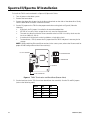
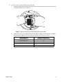
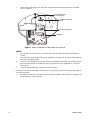
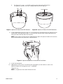
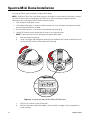
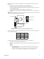
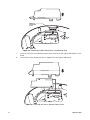
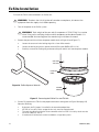
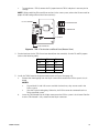
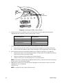
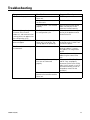
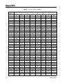
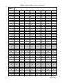
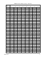
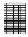
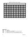
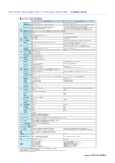
INSTALLATION/OPERATION
TXB-V
Translator Board
C656M-E (4/07)
Contents
Important Safety Instructions. . . . . . . . . . . . . . . . . . . . . . . . . . . . . . . . . . . . . . . . . . . . . . . . . . . . . . . . . . . . . 3
Important Notice. . . . . . . . . . . . . . . . . . . . . . . . . . . . . . . . . . . . . . . . . . . . . . . . . . . . . . . . . . . . . . . . . . . . . . . 3
Regulatory Notices . . . . . . . . . . . . . . . . . . . . . . . . . . . . . . . . . . . . . . . . . . . . . . . . . . . . . . . . . . . . . . . . . . . . . 4
Description . . . . . . . . . . . . . . . . . . . . . . . . . . . . . . . . . . . . . . . . . . . . . . . . . . . . . . . . . . . . . . . . . . . . . . . . . . . 5
Esprit Installation . . . . . . . . . . . . . . . . . . . . . . . . . . . . . . . . . . . . . . . . . . . . . . . . . . . . . . . . . . . . . . . . . . . . . . 6
Spectra III/Spectra IV Installation . . . . . . . . . . . . . . . . . . . . . . . . . . . . . . . . . . . . . . . . . . . . . . . . . . . . . . . . 10
Spectra Mini Dome Installation . . . . . . . . . . . . . . . . . . . . . . . . . . . . . . . . . . . . . . . . . . . . . . . . . . . . . . . . . . 14
ExSite Installation. . . . . . . . . . . . . . . . . . . . . . . . . . . . . . . . . . . . . . . . . . . . . . . . . . . . . . . . . . . . . . . . . . . . . 18
Operation . . . . . . . . . . . . . . . . . . . . . . . . . . . . . . . . . . . . . . . . . . . . . . . . . . . . . . . . . . . . . . . . . . . . . . . . . . . 21
Special Functions Definitions. . . . . . . . . . . . . . . . . . . . . . . . . . . . . . . . . . . . . . . . . . . . . . . . . . . . . . . 21
TXB-V Zone Programming Procedure . . . . . . . . . . . . . . . . . . . . . . . . . . . . . . . . . . . . . . . . . . . . . . . . . 22
Troubleshooting . . . . . . . . . . . . . . . . . . . . . . . . . . . . . . . . . . . . . . . . . . . . . . . . . . . . . . . . . . . . . . . . . . . . . . 23
Appendix. . . . . . . . . . . . . . . . . . . . . . . . . . . . . . . . . . . . . . . . . . . . . . . . . . . . . . . . . . . . . . . . . . . . . . . . . . . . 24
List of Illustrations
1
2
3
4
5
6
7
8
9
10
11
12
13
14
15
16
17
18
19
Esprit System . . . . . . . . . . . . . . . . . . . . . . . . . . . . . . . . . . . . . . . . . . . . . . . . . . . . . . . . . . . . . . . . . . . . 6
TXB-V Termination and Baud Rate (Bottom View) . . . . . . . . . . . . . . . . . . . . . . . . . . . . . . . . . . . . . . . . 7
Installing the TXB-V into the Esprit . . . . . . . . . . . . . . . . . . . . . . . . . . . . . . . . . . . . . . . . . . . . . . . . . . . 7
Installing the Esprit Cover . . . . . . . . . . . . . . . . . . . . . . . . . . . . . . . . . . . . . . . . . . . . . . . . . . . . . . . . . . 8
Fastening the Esprit Cover . . . . . . . . . . . . . . . . . . . . . . . . . . . . . . . . . . . . . . . . . . . . . . . . . . . . . . . . . . 9
TXB-V Termination and Baud Rate (Bottom View) . . . . . . . . . . . . . . . . . . . . . . . . . . . . . . . . . . . . . . . 10
Spectra III/Spectra IV Back Box Interconnect Door . . . . . . . . . . . . . . . . . . . . . . . . . . . . . . . . . . . . . . 11
Spectra III/Spectra IV Back Box Circuit Board . . . . . . . . . . . . . . . . . . . . . . . . . . . . . . . . . . . . . . . . . . 12
Spectra III Dome Drive DIP Switches. . . . . . . . . . . . . . . . . . . . . . . . . . . . . . . . . . . . . . . . . . . . . . . . . 13
Spectra IV Dome Drive DIP Switches. . . . . . . . . . . . . . . . . . . . . . . . . . . . . . . . . . . . . . . . . . . . . . . . . 13
Spectra III/Spectra IV Dome Drive Installation . . . . . . . . . . . . . . . . . . . . . . . . . . . . . . . . . . . . . . . . . 13
Locating the Spectra Mini Dome DIP Switches. . . . . . . . . . . . . . . . . . . . . . . . . . . . . . . . . . . . . . . . . 14
TXB-V Termination and Baud Rate (Bottom View) . . . . . . . . . . . . . . . . . . . . . . . . . . . . . . . . . . . . . . . 15
Removing the Mini Dome Cover and Shorting Plug. . . . . . . . . . . . . . . . . . . . . . . . . . . . . . . . . . . . . . 16
Installing the TXB-V and Mini Dome Cover . . . . . . . . . . . . . . . . . . . . . . . . . . . . . . . . . . . . . . . . . . . . 16
ExSite Spanner Wrench . . . . . . . . . . . . . . . . . . . . . . . . . . . . . . . . . . . . . . . . . . . . . . . . . . . . . . . . . . . 18
Removing the ExSite Pan and Tilt Unit. . . . . . . . . . . . . . . . . . . . . . . . . . . . . . . . . . . . . . . . . . . . . . . . 18
TXB-V Termination and Baud Rate (Bottom View) . . . . . . . . . . . . . . . . . . . . . . . . . . . . . . . . . . . . . . . 19
Installing the TXB-V into the ExSite. . . . . . . . . . . . . . . . . . . . . . . . . . . . . . . . . . . . . . . . . . . . . . . . . . 20
List of Tables
A
2
Receiver Address Settings . . . . . . . . . . . . . . . . . . . . . . . . . . . . . . . . . . . . . . . . . . . . . . . . . . . . . . . . . 24
C656M-E (04/07)
Important Safety Instructions
1. Read these instructions.
2. Keep these instructions.
3. Heed all warnings.
4. Follow all instructions.
5. Only use attachments/accessories specified by the manufacturer.
6. Installation should be done only by qualified personnel and conform to all local codes.
Only use replacement parts recommended by Pelco.
The product and/or manual may bear the following marks:
This symbol indicates that dangerous voltage
constituting a risk of electric shock is present within
this unit.
This symbol indicates that there are important
operating and maintenance instructions in the
literature accompanying this unit.
CAUTION:
RISK OF ELECTRIC SHOCK.
DO NOT OPEN.
Important Notice
All companies make changes and improvements in their products on a regular basis. Because this product
is interfacing with equipment not manufactured by Pelco, the possibility exists that the interface protocols
have changed or are in a different configuration from earlier tested units; therefore, an incompatibility may
occur. The existence of prior successful installations indicates our intent to provide equipment compatible
with other manufacturers, but does not guarantee successful results without on-site integration testing.
Pelco recommends purchasing a single unit for bench testing before the purchase and
installation of this product in quantity. Should any problems occur, Pelco will provide on-site technical
support (North American installations only) to analyze the interface protocols of your system. We will
typically schedule this visit within one week of when the problem is reported to Pelco Technical Support.
Pelco will endeavor, at its expense, to correct the interface incompatibility within two weeks on a high
priority basis. During these visits, the end user must agree to give Pelco reasonable access to the system
in order to study and correct the protocol incompatibility.
In the unlikely event that Pelco is unable to make the translator work in the system, Pelco will accept the
return of any Pelco products associated with the translator and refund the amounts paid for these products
plus freight expenses. Because Pelco recommends a bench test prior to installation, Pelco will not be
liable for any installation costs or lost revenues in the event it cannot solve the compatibility problem.
C656M-E (4/07)
3
Regulatory Notices
This device complies with Part 15 of the FCC Rules. Operation is subject to the following two conditions:
(1) this device may not cause harmful interference, and (2) this device must accept any interference
received, including interference that may cause undesired operation.
RADIO AND TELEVISION INTERFERENCE
This equipment has been tested and found to comply with the limits of a Class B digital device, pursuant to
Part 15 of the FCC Rules. These limits are designed to provide reasonable protection against harmful
interference in a residential installation. This equipment generates, uses, and can radiate radio frequency
energy and, if not installed and used in accordance with the instructions, may cause harmful interference
to radio communications. However there is no guarantee that the interference will not occur in a particular
installation. If this equipment does cause harmful interference to radio or television reception, which can
be determined by turning the equipment off and on, the user is encouraged to try to correct the
interference by one or more of the following measures:
•
Reorient or relocate the receiving antenna.
•
Increase the separation between the equipment and the receiver.
•
Connect the equipment into an outlet on a circuit different from that to which the receiver is
connected.
•
Consult the dealer or an experienced radio/TV technician for help.
You may also find helpful the following booklet, prepared by the FCC: “How to Identify and Resolve RadioTV Interference Problems.” This booklet is available from the U.S. Government Printing Office, Washington
D.C. 20402.
Changes and modifications not expressly approved by the manufacturer or registrant of this equipment can
void your authority to operate this equipment under Federal Communications Commission’s rules.
This Class B digital apparatus complies with Canadian ICES-003.
Cet appareil numérique de la classe B est conforme à la norme NMB-003 du Canada.
The materials used in the manufacture of this document and its components are compliant to
the requirements of Directive 2002/95/EC.
This equipment contains electrical or electronic components that must be recycled properly to
comply with Directive 2002/96/EC of the European Union regarding the disposal of waste
electrical and electronic equipment (WEEE). Contact your local dealer for procedures for
recycling this equipment.
4
C656M-E (4/07)
Description
The TXB-V translator board allows Vicon® controllers to communicate with Pelco’s ExSite™, Esprit®, and
Spectra® systems. After setup, the controller functions the same as a Vicon controller normally would,
except as noted in the Operation section on page 21.
The TXB-V translator board has been tested and shown to work with the following Vicon systems:
•
V1300X-DVC Remote Control Panel
•
VPS324 Matrix Controller
•
V1422™ Matrix Controller
•
V4480SCC Matrix 44® Card Cage
•
V6680SCC Matrix 66™ Card Cage
Based on the information published by the manufacturer, Pelco has reason to believe that the translator
board will also work with the following Vicon models:
•
VPS1344™ Matrix Switching System
•
V1300 Series NOVA™ Programmable Matrix Switching System
•
V1400X-DVC System Console Control Station
Parts List
The following items are supplied:
1 TXB-V translator board (printed circuit board)
1 6-32 screw with lock washer (for Spectra III™/Spectra IV Series only)
1 4-40 screw with lock washer (unused)
C656M-E (4/07)
5
Esprit Installation
To install the TXB-V translator board in an Esprit system (refer to Figure 1):
1. Turn off power to the Esprit system.
2. Remove the left cover from the pan and tilt.
3. Remove the shorting plug from the 16-pin connector on the Esprit system’s circuit board.
4. Remove the nut and washer from the standoff on the Esprit system’s circuit board.
NOTES:
•
Discard the 6-32 and 4-40 screws and their lock washers; they are not used in the Esprit system.
•
Save the 16-pin shorting plug. Otherwise, the Esprit cannot be converted back to a Pelco-controlled
system.
SW2 SW1
ON
OFF 1 2 3 4 5 6 7 8
ON
OFF 1 2 3 4 5 6 7 8
DIP SWITCHES
NYLON
WASHER
PHILLIPS
SCREW
ESPRIT CIRCUIT BOARD
16-PIN CONNECTOR
REMOVE SHORTING PLUG
STANDOFF WITH
NUT AND WASHER
Figure 1. Esprit System
5. Set the P2 jumper on the TXB-V to the proper termination setting (refer to Figure 2). Note the
following:
•
•
•
•
•
By default, the P2 jumper is installed in the unterminated position.
All TXB-Vs in a daisy chain, except the last unit, must be unterminated.
The total wire distance from the Vicon controller to the last TXB-V in a daisy chain must be
less than 4,000 ft (1,219 m).
A maximum of 10 receivers can be installed on a single daisy chain.
To unterminate a TXB-V, remove the P2 jumper from the TXB-V and place it over one pin for
storage.
NOTE: When combining Pelco and Vicon receivers in the same system, refer to the Vicon manual for
proper RS-485 configuration of the Vicon receiver(s).
6
C656M-E (4/07)
P3 & P4 JUMPERS
P2 UNTERMINATED
P2 TERMINATED
P2 JUMPER
16-PIN CONNECTOR
Figure 2. TXB-V Termination and Baud Rate (Bottom View)
6. Set the baud rate for the TXB-V translator board (from the controller). Use the P3 and P4 jumpers
(refer to the following table).
Baud
P3
600
OFF
P4
OFF
4800*
ON
ON
9600
OFF
ON
19.2K
ON
OFF
*Factory default.
7. Install the TXB-V on the Esprit circuit board (refer to Figure 3):
a.
Insert the 16-pin connector on the bottom of the TXB-V into the mating 16-pin connector on
the Esprit circuit board.
b.
Reinstall the nut and washer on the standoff to secure the TXB-V to the Esprit circuit board.
STANDOFF
16-PIN CONNECTOR
STANDOFF NUT
AND WASHER
Figure 3. Installing the TXB-V into the Esprit
8. Set the DIP switches on the Esprit system (refer to Figure 1 on page 6 for switch location):
a.
SW1: Set all SW1 switches to the OFF position.
b.
SW2: Set the Esprit address (refer to Table A on page 24 of the Appendix for switch settings).
C656M-E (4/07)
7
9. Reinstall the left cover of the pan and tilt:
WARNING: Make sure you seal the unit. Otherwise, moisture could disable or damage
the Esprit.
a.
Properly position the cover and slide it into place. The sides of the cover must fit under the
front and back rain guards of the pan and tilt. The top of the cover must seat against the lip of
the top gasket. (Refer to Figure 4.)
NOT SEALED
CORRECT
INCORRECT
GAP
Figure 4. Installing the Esprit Cover
8
b.
Apply pressure and push the top of the cover down to align the screw holes (refer to Figure 5).
c.
Insert the Phillips screw and washer. Tighten until the screw will not turn.
C656M-E (4/07)
TOP GASKET
FRONT
RAIN
GUARD
Figure 5. Fastening the Esprit Cover
10. Remove the pan and tilt from the base of the Esprit system.
11. Check the control wiring inside the base of the unit. Refer to the Esprit documentation and the
documentation supplied with your controller to make sure the wiring is correct.
Vicon Controller
Terminal Block J1
Esprit
Wire Harness
Pin 9 Response Out +
White (TX+)
Pin 8 Response Out -
Black (TX-)
Pin 3 Command In +
Red (RX+)
Pin 2 Command In -
Green (RX-)
12. Reattach the pan and tilt onto the base of the unit.
13. Apply power to the system. The following message appears on the monitor as soon as the Esprit
configuration cycle is completed:
TXB-V REV x.xx
NOTE: x.xx represents the current firmware revision.
C656M-E (4/07)
9
Spectra III/Spectra IV Installation
To install the TXB-V translator board in a Spectra III/Spectra IV Series:
1. Turn off power to the dome system.
2. Remove the lower dome.
3. Remove the dome drive by pressing in the blue and red tabs on the sides of the dome drive. Gently
rock the dome drive to release it from the back box.
4. Set the P2 jumper on the TXB-V to the proper termination setting (refer to Figure 6). Note the
following:
•
•
•
•
•
By default, the P2 jumper is installed in the unterminated position.
All TXB-Vs in a daisy chain, except the last unit, must be unterminated.
The total wire distance from the Vicon controller to the last TXB-V in a daisy chain must be
less than 4,000 ft (1,219 m).
A maximum of 10 receivers can be installed on a single daisy chain.
To unterminate a TXB-V, remove the P2 jumper from the TXB-V and place it over one pin for
storage.
NOTE: When combining Pelco and Vicon receivers in the same system, refer to the Vicon manual for
proper RS-485 configuration of the Vicon receiver(s).
P3 & P4 JUMPERS
P2 UNTERMINATED
P2 TERMINATED
P2 JUMPER
16-PIN CONNECTOR
Figure 6. TXB-V Termination and Baud Rate (Bottom View)
5. Set the baud rate for the TXB-V translator board (from the controller). Use the P3 and P4 jumpers
(refer to the following table).
Baud
P3
600
OFF
P4
OFF
4800*
ON
ON
9600
OFF
ON
19.2K
ON
OFF
*Factory default.
10
C656M-E (4/07)
6. Install the TXB-V translator board into the back box:
a.
Open the hinged door to the back box. Push the tab lock towards the back box wall of the unit
and open the door (refer to Figure 7).
Figure 7. Spectra III/Spectra IV Back Box Interconnect Door
b.
C656M-E (4/07)
Check the wiring to the controller. Refer to the Spectra III/Spectra IV documentation and the
documentation supplied with your controller to make sure the wiring is correct.
Vicon Controller
Terminal Block J1
Spectra III/Spectra IV
Four-Wire Terminal Block
Pin 9 Response Out +
TX+
Pin 8 Response Out -
TX-
Pin 3 Command In +
RX+
Pin 2 Command In -
RX-
11
c.
Remove the shorting plug from the 16-pin connector located on the back box circuit board
(refer to Figure 8).
6-32 SCREW AND
LOCK WASHER
REMOVE SHORTING
PLUG
16-PIN CONNECTOR
STANDOFF
Figure 8. Spectra III/Spectra IV Back Box Circuit Board
NOTES:
•
•
Discard the 4-40 screw and its lock washer; they are not used in the Spectra III/Spectra IV
system.
Save the 16-pin shorting plug. Otherwise, the Spectra III/Spectra IV cannot be converted back
to a Pelco-controlled system.
d.
Insert the TXB-V board into the 16-pin connector located on the back box circuit board. Secure
the translator board to the standoff on the circuit board using the supplied 6-32 screw and
lock washer.
e.
Close the interconnect door. Snap the tab lock into place.
7. Set the DIP switches on the Spectra III/Spectra IV system (refer to Figure 9 and Figure 10 on page 13
for switch locations):
a.
12
Set the SW1 switches on the dome drive to assign the address (refer to Table A on page 24 of
the Appendix for switch settings).
C656M-E (4/07)
b.
For Spectra III systems, set all SW3 switches on the dome to the OFF position.
For Spectra IV systems, set SW2-1 through SW2-8 to the OFF position.
SW1 SW3
SW2
SW1 AND SW2
1 2 3 4 5 6 7 8
1
1 2 3 4 5 6 7 8
SW1
SW3
on SW2 on
Figure 9. Spectra III Dome Drive DIP Switches
Figure 10. Spectra IV Dome Drive DIP Switches
8. Install the dome drive (refer to Figure 11). Line up the blue (A) and red (B) tabs with the blue (A) and
red (B) labels. When pushing the tabs in, insert one side, then the other. Continue pushing on the
ends of the tabs until both tabs click into place.
NOTE: Refer to the installation manual supplied with the Spectra III/Spectra IV dome for instructions
on installing the back box, dome drive, and lower dome.
Figure 11. Spectra III/Spectra IV Dome Drive Installation
9. Install the lower dome.
10. Apply power to the system. The following message appears on the monitor as soon as the
Spectra III/Spectra IV configuration cycle is completed:
TXB-V REV x.xx
NOTE: x.xx represents the current firmware revision.
C656M-E (4/07)
13
Spectra Mini Dome Installation
To install the TXB-V translator board in a Spectra Mini dome:
NOTE: Installing a TXB-V into a mini dome increases unit height. In surface mount installations, you must
cut a hole in the surface to accommodate the TXB-V cover. For an installation template and more
information, refer to the Spectra Mini Dome Installation manual.
1. Turn off power to the dome system.
2. If the Spectra Mini dome is already installed, remove it to access the top of the dome drive where
the translator board will be installed.
3. Place the dome drive on a flat surface with the dome liner pointing up.
4. Set the DIP switches on the dome (refer to Figure 12 for switch location):
NOTE: There are no SW1 switch settings on the Spectra Mini dome.
a.
Point the camera straight up.
b.
Using a flashlight, look through the viewing slot of the dome liner. Rotate the dome liner until
you see two DIP switches in the bottom of the housing.
ON
SW 3
SW 2
ON
Figure 12. Locating the Spectra Mini Dome DIP Switches
14
c.
SW2: Set all switches to the OFF position.
d.
SW3: Set the Spectra Mini dome address (refer to Table A on page 24 of the Appendix for
switch settings).
C656M-E (4/07)
5. Set the P2 jumper on the TXB-V to the proper termination setting (refer to Figure 13). Note the
following:
•
•
•
•
•
By default, the P2 jumper is installed in the unterminated position.
All TXB-Vs in a daisy chain, except the last unit, must be unterminated.
The total wire distance from the Vicon controller to the last TXB-V in a daisy chain must be
less than 4,000 ft (1,219 m).
A maximum of 10 receivers can be installed on a single daisy chain.
To unterminate a TXB-V, remove the P2 jumper from the TXB-V and place it over one pin for
storage.
NOTE: When combining Pelco and Vicon receivers in the same system, refer to the Vicon manual for
proper RS-485 configuration of the Vicon receiver(s).
P3 & P4 JUMPERS
P2 UNTERMINATED
P2 TERMINATED
P2 JUMPER
16-PIN CONNECTOR
Figure 13. TXB-V Termination and Baud Rate (Bottom View)
6. Set the baud rate for the TXB-V translator board (from the controller). Use the P3 and P4 jumpers
(refer to the following table).
Baud
P3
600
OFF
P4
OFF
4800*
ON
ON
9600
OFF
ON
19.2K
ON
OFF
*Factory default.
7. Install the TXB-V translator board (refer to Figure 14 and Figure 15 on page 16):
a.
Remove the cover from the top of the dome drive.
b.
Remove the shorting plug from the 16-pin connector located on the Spectra Mini dome circuit
board.
NOTES:
•
•
C656M-E (4/07)
Discard the 4-40 and 6-32 screws and their lock washers; they are not used in the
Spectra Mini dome.
Save the 16-pin shorting plug and the original cover from the Spectra Mini dome.
Otherwise, the unit cannot be converted back to a Pelco-controlled system.
15
REMOVE
SHORTING
PLUG
Figure 14. Removing the Mini Dome Cover and Shorting Plug
c.
Insert the TXB-V translator board into the 16-pin connector on the Spectra Mini dome’s circuit
board.
d.
Install the translator board cover that is supplied with the Spectra Mini dome.
Figure 15. Installing the TXB-V and Mini Dome Cover
16
C656M-E (4/07)
8. Check the wiring to the controller. Refer to the Spectra Mini dome documentation and the
documentation supplied with your controller to make sure the wiring is correct.
Vicon Controller
Terminal Block J1
Spectra Mini Dome
RJ45-10 Connector
Pin 9 Response Out +
Pin 6 (TX+)
Pin 8 Response Out -
Pin 5 (TX-)
Pin 3 Command In +
Pin 4 (RX+)
Pin 2 Command In -
Pin 3 (RX-)
9. Refer to the installation manual for the Spectra Mini dome to complete the installation.
10. Apply power to the system. The following message appears on the monitor as soon as the Spectra
Mini dome configuration cycle is completed:
TXB-V REV x.xx
NOTE: x.xx represents the current firmware revision.
C656M-E (4/07)
17
ExSite Installation
To install the TXB-V translator board in an ExSite unit:
WARNING: To reduce the risk of ignition of hazardous atmospheres, disconnect the
equipment from the supply circuit before opening.
1. Turn off the power to the ExSite system.
WARNING: Total weight of the pan and tilt component is 55 lb (25 kg). Use caution
when lifting and assembling the pan and tilt component on the power module. It is
recommended that nonslip gloves be worn during installation or removal.
2. Remove the pan and tilt unit from the power module (refer to Figure 16 and Figure 17):
a.
Loosen the setscrew in the locking ring with a 2 mm Allen wrench.
b.
Loosen the locking ring with a spanner wrench (Pelco part #MF00-1251-121A).
c.
Carefully unscrew the locking ring and remove the pan and tilt unit from the power module.
PAN AND
TILT UNIT
LOCKING
RING
Figure 16. ExSite Spanner Wrench
POWER
MODULE
Figure 17. Removing the ExSite Pan and Tilt Unit
3. Set the P2 jumper on the TXB-V to the proper termination setting (refer to Figure 18 on page 19).
Note the following:
•
•
•
•
18
By default, the P2 jumper is installed in the unterminated position.
All TXB-Vs in a daisy chain, except the last unit, must be unterminated.
The total wire distance from the Vicon controller to the last TXB-V in a daisy chain must be
less than 4,000 ft (1,219 m).
A maximum of 10 receivers can be installed on a single daisy chain.
C656M-E (4/07)
•
To unterminate a TXB-V, remove the P2 jumper from the TXB-V and place it over one pin for
storage.
NOTE: When combining Pelco and Vicon receivers in the same system, refer to the Vicon manual for
proper RS-485 configuration of the Vicon receiver(s).
P3 & P4 JUMPERS
P2 UNTERMINATED
P2 TERMINATED
P2 JUMPER
16-PIN CONNECTOR
Figure 18. TXB-V Termination and Baud Rate (Bottom View)
4. Set the baud rate for the TXB-V translator board (from the controller). Use the P3 and P4 jumpers
(refer to the following table).
Baud
P3
600
OFF
P4
OFF
4800*
ON
ON
9600
OFF
ON
19.2K
ON
OFF
*Factory default.
5. Install the TXB-V board on the power module (refer to Figure 19 on page 20):
a.
Remove the shorting plug from the 16-pin connector located on the ExSite system’s circuit
board.
NOTES:
•
•
Discard the 6-32 and 4-40 screws and their lock washers; they are not used in the
ExSite system.
Save the 16-pin shorting plug. Otherwise, the ExSite cannot be converted back to a
Pelco-controlled system.
b.
Insert the TXB-V board into the 16-pin connector on the ExSite system’s circuit board. Confirm
that the TXB-V board is fully seated into the 16-pin connector.
C656M-E (4/07)
19
16-PIN
CONNECTOR
SW1
SW3
Figure 19. Installing the TXB-V into the ExSite
6. Check the wiring to the controller. Refer to the ExSite documentation and the documentation
supplied with your controller to make sure the wiring is correct.
Vicon Controller
Terminal Block J1
ExSite
Wire Harness
Pin 9 Response Out +
White/Orange (TX+)
Pin 8 Response Out -
White/Blue (TX-)
Pin 3 Command In +
Red (RX+)
Pin 2 Command In -
Green (RX-)
7. Set the DIP switches on the ExSite system (refer to Figure 19 for switch location):
a.
SW3: Verify that all SW3 switches on the ExSite power module are set to the OFF position.
b.
SW1: Set the ExSite address (refer to Table A on page 24 of the Appendix for switch settings).
8. Attach the pan and tilt unit to the power module (refer to Figure 16 and Figure 17 on page 18):
a.
Align the pan and tilt unit with the power module. Carefully begin to hand tighten the locking
ring onto the threads of the power module.
b.
Continue to tighten the locking ring with a spanner wrench.
c.
Tighten the setscrew in the locking ring with a 2 mm Allen wrench.
NOTE: Refer to the installation manual supplied with the ExSite system for instructions on attaching
the pan and tilt unit to the power module.
9. Apply power to the system. The following message appears on the monitor as soon as the ExSite
configuration cycle is completed:
TXB-V REV x.xx
NOTE: x.xx represents the current firmware version.
20
C656M-E (4/07)
Operation
Set preset 94 to access the camera menus. Press Iris Open to select menu items. The following table
shows how the Vicon keyboard relates to the Pelco translator. Refer to your Vicon documentation for
operating instructions.
SPECIAL FUNCTIONS DEFINITIONS
Vicon Keyboard
Unit Function
Pelco Function
Pan, tilt, zoom, focus, and
iris functions
Moves unit accordingly
Pan, tilt, zoom, focus, and iris
functions
(Keyboard in PGM Mode)
1-32 Preset
33-64 Preset
Saves camera position as preset 1-32
Saves camera position as preset 33-64
Sets preset 1-32
Sets preset 35-66
AUX toggle 1-2 (On/Off)
AUX toggle 3-6
Activates auxiliaries 1-2
No action on Pelco receivers
Toggles auxiliaries 1-2 on/off
Ignored
Auto pan toggle (On)
Auto pan toggle (Off)
Runs auto pan
Stops auto pan
Calls preset 99
Calls preset 96
(Keyboard in RUN Mode)
1-32 Preset
33-64 Preset
65 Preset
66 Preset
67-87 Preset
88 Preset
89 Preset
90 Preset
91 Preset
92 Preset
96 Preset
97 Preset
98 Preset
99 Preset
Moves camera to preset position 1-32
Moves camera to preset position 33-64
Camera flips 180 degrees
Pans to zero
No action
Runs pattern 1 (short)
Runs pattern 2 (short)
Runs long pattern
Inserts IR filter*
Removes IR filter*
Stops scanning
Runs random scan
Runs frame scan
Runs auto scan
Calls preset 1-32
Calls preset 35-66
Calls preset 33
Calls preset 34
Ignored
Calls pattern #1
Calls pattern #2
Calls long pattern
Calls preset 88
Calls preset 89
Calls preset 96 (stop scan)
Calls preset 97
Calls preset 98
Calls preset 99
(Keyboard in PGM Mode)
65-79 Preset
80-87 Preset
Auto pan key
88 Preset
89 Preset
90 Preset
91 Preset
92 Preset
93 Preset
94 Preset
95 Preset
96 Preset
97 Preset
98 Preset
99 Preset
Lens speed toggle
No action
Sets start point (left limit) of zones 1-8
Sets end point (right limit) of zones 1-8
Begins programming pattern #1
Begins programming pattern #2
Begins programming long pattern
Ends programming of a pattern
Sets manual pan left limit***
Sets manual pan right limit***
Shows program menu**
Enables zone label display
Disables zone label display
Performs power-on reset
Sets Auto pan left limit***
Sets Auto pan right limit***
Sets zoom speed
Ignored
Sets zone 1-8 start
Sets zone 1-8 end
Sets pattern #1 (short)
Sets pattern #2 (short)
Sets long pattern (#0)
Ends pattern programming
Sets preset 90
Sets preset 91
Sets preset 95
Displays zone label
Returns to normal screen
Remote reset
Sets preset 92
Sets preset 93
Toggles through zoom speeds
Auto iris toggle (On/Off)
Controls auto iris
Auto on/off
*Spectra SD53CBW family, Spectra SD435 family, Esprit ES30CBW18 family, Esprit ES31CBW18
family, ExSite IPSXM30CBW family, ExSite IPSXM31CBW family, ExSite EHXM30CBW family,
and ExSite EHXM31CBW family.
**Iris Open selects menu items.
***Refer to the Pelco system operation manuals for details on how to clear limit stops.
C656M-E (4/07)
21
TXB-V ZONE PROGRAMMING PROCEDURE
A zone is a pan area, defined by a left and right limit, on the 360-degree pan plane. To program a zone
using a Vicon controller (refer to the manual supplied with the controller):
Step
1. Set left zone limit.
Procedure
a. Position the Pelco unit at the left limit of the zone.
b. Issue the zone start command (PRG 8# PRESET) for the zone
number being programmed; # is a number between 0 and 7 that
represents zones 1 through 8.
2. Set right zone limit.
a. Position the Pelco unit at the right limit of the zone.
b. Issue the zone end command by pressing the Auto Pan key.
3. Enable the zone label display.
Issue the enable zone label command (PRG 95 PRESET) to display
the zone label.
IMPORTANT: (Spectra III/Spectra IV and ExSite systems only): After programming a zone, always enable
the zone through the Pelco unit programming menu. Refer to the operation/programming manual supplied
with the Pelco system.
Operation Notes:
1. Focus speed cannot be set with the Vicon controller.
2. The Event Tour function on the Vicon controller does not function.
3. On-screen titling is only available on Spectra III/Spectra IV (v1.28 and higher).
4. Zone labels use only defaults (Zone 1, Zone 2, etc.)
5. Upon completion of pattern programming, issue an end pattern command (91 Set on the Vicon
controller) to enable Turbo speed during panning. If this is not done, Turbo speed will be unavailable
until 10 minutes after starting pattern programming.
6. Alarms from the Pelco receiver will not activate alarm LEDs on the Vicon controller.
7. LEDs on the Vicon controller may be out of sync when the receiver’s start-up defaults are changed,
when the receiver is reset, or if a receiver alarm triggers a status change. To correct, press and
release the affected key.
8. The communication parameters that are displayed momentarily on the selected monitor immediately
after initial power-up pertain only to the communication link between the translator board and the
Pelco unit. Communication parameters between the translator board and the Vicon controller are
selected with jumpers P3 and P4.
22
C656M-E (4/07)
Troubleshooting
Symptom
Possible Cause
Suggested Remedy
No video is displayed.
Power is not connected to the
Pelco unit.
Check the power connector.
Video cable is not connected to
the Pelco unit.
Check the video connector.
Translator board is not inserted
properly.
Reinstall the translator board.
Make sure the pins on the
board are inserted correctly.
Pelco unit information (model,
firmware, Pelco P and D
addresses, and communication
settings) does not appear after
the configuration cycle.
The Pelco unit cannot complete
its configuration cycle.
Refer to the troubleshooting
section of the product manual
for the Pelco unit.
The message “TXB-V REV x.xx”
does not appear.
The baud rate setting on the
Pelco unit is not correct. The
setting appears on power-up.
Make sure the baud rate setting
on the Pelco unit is 2400. Then
cycle device power.
The Pelco unit does not respond
to commands.
The unit address is not correct.
Make sure the Pelco unit
(receiver) address is correct.
This address can range from 1
to 255.
Make sure the controller is
addressing the correct Pelco
unit.
C656M-E (4/07)
The receiving and transmitting
lines are not connected
properly.
Make sure the TX+, TX-, RX+,
and RX- lines are properly
connected. (Refer to the wiring
tables in this manual as well as
the troubleshooting section of
the product manual for the
controller.)
The command was lost
between the controller and the
Pelco unit.
Retry the command.
23
Appendix
Table A. Receiver Address Settings
24
Switch Setting
Receiver
Address
1
2
3
4
5
6
7
8
1
ON
OFF
OFF
OFF
OFF
OFF
OFF
OFF
2
OFF
ON
OFF
OFF
OFF
OFF
OFF
OFF
3
ON
ON
OFF
OFF
OFF
OFF
OFF
OFF
4
OFF
OFF
ON
OFF
OFF
OFF
OFF
OFF
5
ON
OFF
ON
OFF
OFF
OFF
OFF
OFF
6
OFF
ON
ON
OFF
OFF
OFF
OFF
OFF
7
ON
ON
ON
OFF
OFF
OFF
OFF
OFF
8
OFF
OFF
OFF
ON
OFF
OFF
OFF
OFF
9
ON
OFF
OFF
ON
OFF
OFF
OFF
OFF
10
OFF
ON
OFF
ON
OFF
OFF
OFF
OFF
11
ON
ON
OFF
ON
OFF
OFF
OFF
OFF
12
OFF
OFF
ON
ON
OFF
OFF
OFF
OFF
13
ON
OFF
ON
ON
OFF
OFF
OFF
OFF
14
OFF
ON
ON
ON
OFF
OFF
OFF
OFF
15
ON
ON
ON
ON
OFF
OFF
OFF
OFF
16
OFF
OFF
OFF
OFF
ON
OFF
OFF
OFF
17
ON
OFF
OFF
OFF
ON
OFF
OFF
OFF
18
OFF
ON
OFF
OFF
ON
OFF
OFF
OFF
OFF
19
ON
ON
OFF
OFF
ON
OFF
OFF
20
OFF
OFF
ON
OFF
ON
OFF
OFF
OFF
21
ON
OFF
ON
OFF
ON
OFF
OFF
OFF
22
OFF
ON
ON
OFF
ON
OFF
OFF
OFF
23
ON
ON
ON
OFF
ON
OFF
OFF
OFF
24
OFF
OFF
OFF
ON
ON
OFF
OFF
OFF
25
ON
OFF
OFF
ON
ON
OFF
OFF
OFF
26
OFF
ON
OFF
ON
ON
OFF
OFF
OFF
27
ON
ON
OFF
ON
ON
OFF
OFF
OFF
28
OFF
OFF
ON
ON
ON
OFF
OFF
OFF
29
ON
OFF
ON
ON
ON
OFF
OFF
OFF
30
OFF
ON
ON
ON
ON
OFF
OFF
OFF
31
ON
ON
ON
ON
ON
OFF
OFF
OFF
32
OFF
OFF
OFF
OFF
OFF
ON
OFF
OFF
33
ON
OFF
OFF
OFF
OFF
ON
OFF
OFF
34
OFF
ON
OFF
OFF
OFF
ON
OFF
OFF
OFF
35
ON
ON
OFF
OFF
OFF
ON
OFF
36
OFF
OFF
ON
OFF
OFF
ON
OFF
OFF
37
ON
OFF
ON
OFF
OFF
ON
OFF
OFF
C656M-E (4/07)
Table A. Receiver Address Settings (Continued)
Switch Setting
Receiver
Address
1
2
3
4
5
6
7
8
38
OFF
ON
ON
OFF
OFF
ON
OFF
OFF
OFF
39
ON
ON
ON
OFF
OFF
ON
OFF
40
OFF
OFF
OFF
ON
OFF
ON
OFF
OFF
41
ON
OFF
OFF
ON
OFF
ON
OFF
OFF
42
OFF
ON
OFF
ON
OFF
ON
OFF
OFF
43
ON
ON
OFF
ON
OFF
ON
OFF
OFF
44
OFF
OFF
ON
ON
OFF
ON
OFF
OFF
45
ON
OFF
ON
ON
OFF
ON
OFF
OFF
46
OFF
ON
ON
ON
OFF
ON
OFF
OFF
OFF
47
ON
ON
ON
ON
OFF
ON
OFF
48
OFF
OFF
OFF
OFF
ON
ON
OFF
OFF
49
ON
OFF
OFF
OFF
ON
ON
OFF
OFF
50
OFF
ON
OFF
OFF
ON
ON
OFF
OFF
51
ON
ON
OFF
OFF
ON
ON
OFF
OFF
52
OFF
OFF
ON
OFF
ON
ON
OFF
OFF
53
ON
OFF
ON
OFF
ON
ON
OFF
OFF
54
OFF
ON
ON
OFF
ON
ON
OFF
OFF
55
ON
ON
ON
OFF
ON
ON
OFF
OFF
56
OFF
OFF
OFF
ON
ON
ON
OFF
OFF
57
ON
OFF
OFF
ON
ON
ON
OFF
OFF
58
OFF
ON
OFF
ON
ON
ON
OFF
OFF
59
ON
ON
OFF
ON
ON
ON
OFF
OFF
60
OFF
OFF
ON
ON
ON
ON
OFF
OFF
61
ON
OFF
ON
ON
ON
ON
OFF
OFF
62
OFF
ON
ON
ON
ON
ON
OFF
OFF
63
ON
ON
ON
ON
ON
ON
OFF
OFF
64
OFF
OFF
OFF
OFF
OFF
OFF
ON
OFF
65
ON
OFF
OFF
OFF
OFF
OFF
ON
OFF
66
OFF
ON
OFF
OFF
OFF
OFF
ON
OFF
OFF
67
ON
ON
OFF
OFF
OFF
OFF
ON
68
OFF
OFF
ON
OFF
OFF
OFF
ON
OFF
69
ON
OFF
ON
OFF
OFF
OFF
ON
OFF
70
OFF
ON
ON
OFF
OFF
OFF
ON
OFF
71
ON
ON
ON
OFF
OFF
OFF
ON
OFF
72
OFF
OFF
OFF
ON
OFF
OFF
ON
OFF
73
ON
OFF
OFF
ON
OFF
OFF
ON
OFF
74
OFF
ON
OFF
ON
OFF
OFF
ON
OFF
75
ON
ON
OFF
ON
OFF
OFF
ON
OFF
76
OFF
OFF
ON
ON
OFF
OFF
ON
OFF
77
ON
OFF
ON
ON
OFF
OFF
ON
OFF
C656M-E (4/07)
25
Table A. Receiver Address Settings (Continued)
26
Switch Setting
Receiver
Address
1
2
3
4
5
6
7
8
78
OFF
ON
ON
ON
OFF
OFF
ON
OFF
OFF
79
ON
ON
ON
ON
OFF
OFF
ON
80
OFF
OFF
OFF
OFF
ON
OFF
ON
OFF
81
ON
OFF
OFF
OFF
ON
OFF
ON
OFF
82
OFF
ON
OFF
OFF
ON
OFF
ON
OFF
83
ON
ON
OFF
OFF
ON
OFF
ON
OFF
84
OFF
OFF
ON
OFF
ON
OFF
ON
OFF
85
ON
OFF
ON
OFF
ON
OFF
ON
OFF
86
OFF
ON
ON
OFF
ON
OFF
ON
OFF
87
ON
ON
ON
OFF
ON
OFF
ON
OFF
88
OFF
OFF
OFF
ON
ON
OFF
ON
OFF
89
ON
OFF
OFF
ON
ON
OFF
ON
OFF
90
OFF
ON
OFF
ON
ON
OFF
ON
OFF
OFF
91
ON
ON
OFF
ON
ON
OFF
ON
92
OFF
OFF
ON
ON
ON
OFF
ON
OFF
93
ON
OFF
ON
ON
ON
OFF
ON
OFF
94
OFF
ON
ON
ON
ON
OFF
ON
OFF
95
ON
ON
ON
ON
ON
OFF
ON
OFF
96
OFF
OFF
OFF
OFF
OFF
ON
ON
OFF
97
ON
OFF
OFF
OFF
OFF
ON
ON
OFF
98
OFF
ON
OFF
OFF
OFF
ON
ON
OFF
99
ON
ON
OFF
OFF
OFF
ON
ON
OFF
100
OFF
OFF
ON
OFF
OFF
ON
ON
OFF
101
ON
OFF
ON
OFF
OFF
ON
ON
OFF
102
OFF
ON
ON
OFF
OFF
ON
ON
OFF
103
ON
ON
ON
OFF
OFF
ON
ON
OFF
104
OFF
OFF
OFF
ON
OFF
ON
ON
OFF
105
ON
OFF
OFF
ON
OFF
ON
ON
OFF
106
OFF
ON
OFF
ON
OFF
ON
ON
OFF
107
ON
ON
OFF
ON
OFF
ON
ON
OFF
108
OFF
OFF
ON
ON
OFF
ON
ON
OFF
109
ON
OFF
ON
ON
OFF
ON
ON
OFF
110
OFF
ON
ON
ON
OFF
ON
ON
OFF
111
ON
ON
ON
ON
OFF
ON
ON
OFF
112
OFF
OFF
OFF
OFF
ON
ON
ON
OFF
113
ON
OFF
OFF
OFF
ON
ON
ON
OFF
114
OFF
ON
OFF
OFF
ON
ON
ON
OFF
115
ON
ON
OFF
OFF
ON
ON
ON
OFF
116
OFF
OFF
ON
OFF
ON
ON
ON
OFF
117
ON
OFF
ON
OFF
ON
ON
ON
OFF
C656M-E (4/07)
Table A. Receiver Address Settings (Continued)
Switch Setting
Receiver
Address
1
2
3
4
5
6
7
8
118
OFF
ON
ON
OFF
ON
ON
ON
OFF
119
ON
ON
ON
OFF
ON
ON
ON
OFF
120
OFF
OFF
OFF
ON
ON
ON
ON
OFF
121
ON
OFF
OFF
ON
ON
ON
ON
OFF
122
OFF
ON
OFF
ON
ON
ON
ON
OFF
123
ON
ON
OFF
ON
ON
ON
ON
OFF
124
OFF
OFF
ON
ON
ON
ON
ON
OFF
125
ON
OFF
ON
ON
ON
ON
ON
OFF
126
OFF
ON
ON
ON
ON
ON
ON
OFF
127
ON
ON
ON
ON
ON
ON
ON
OFF
128
OFF
OFF
OFF
OFF
OFF
OFF
OFF
ON
129
ON
OFF
OFF
OFF
OFF
OFF
OFF
ON
130
OFF
ON
OFF
OFF
OFF
OFF
OFF
ON
131
ON
ON
OFF
OFF
OFF
OFF
OFF
ON
132
OFF
OFF
ON
OFF
OFF
OFF
OFF
ON
133
ON
OFF
ON
OFF
OFF
OFF
OFF
ON
134
OFF
ON
ON
OFF
OFF
OFF
OFF
ON
135
ON
ON
ON
OFF
OFF
OFF
OFF
ON
136
OFF
OFF
OFF
ON
OFF
OFF
OFF
ON
137
ON
OFF
OFF
ON
OFF
OFF
OFF
ON
138
OFF
ON
OFF
ON
OFF
OFF
OFF
ON
139
ON
ON
OFF
ON
OFF
OFF
OFF
ON
140
OFF
OFF
ON
ON
OFF
OFF
OFF
ON
141
ON
OFF
ON
ON
OFF
OFF
OFF
ON
142
OFF
ON
ON
ON
OFF
OFF
OFF
ON
143
ON
ON
ON
ON
OFF
OFF
OFF
ON
144
OFF
OFF
OFF
OFF
ON
OFF
OFF
ON
145
ON
OFF
OFF
OFF
ON
OFF
OFF
ON
146
OFF
ON
OFF
OFF
ON
OFF
OFF
ON
147
ON
ON
OFF
OFF
ON
OFF
OFF
ON
148
OFF
OFF
ON
OFF
ON
OFF
OFF
ON
149
ON
OFF
ON
OFF
ON
OFF
OFF
ON
150
OFF
ON
ON
OFF
ON
OFF
OFF
ON
151
ON
ON
ON
OFF
ON
OFF
OFF
ON
152
OFF
OFF
OFF
ON
ON
OFF
OFF
ON
153
ON
OFF
OFF
ON
ON
OFF
OFF
ON
154
OFF
ON
OFF
ON
ON
OFF
OFF
ON
155
ON
ON
OFF
ON
ON
OFF
OFF
ON
156
OFF
OFF
ON
ON
ON
OFF
OFF
ON
157
ON
OFF
ON
ON
ON
OFF
OFF
ON
C656M-E (4/07)
27
Table A. Receiver Address Settings (Continued)
28
Switch Setting
Receiver
Address
1
2
3
4
5
6
7
8
158
OFF
ON
ON
ON
ON
OFF
OFF
ON
159
ON
ON
ON
ON
ON
OFF
OFF
ON
160
OFF
OFF
OFF
OFF
OFF
ON
OFF
ON
161
ON
OFF
OFF
OFF
OFF
ON
OFF
ON
162
OFF
ON
OFF
OFF
OFF
ON
OFF
ON
163
ON
ON
OFF
OFF
OFF
ON
OFF
ON
164
OFF
OFF
ON
OFF
OFF
ON
OFF
ON
165
ON
OFF
ON
OFF
OFF
ON
OFF
ON
166
OFF
ON
ON
OFF
OFF
ON
OFF
ON
167
ON
ON
ON
OFF
OFF
ON
OFF
ON
168
OFF
OFF
OFF
ON
OFF
ON
OFF
ON
169
ON
OFF
OFF
ON
OFF
ON
OFF
ON
170
OFF
ON
OFF
ON
OFF
ON
OFF
ON
171
ON
ON
OFF
ON
OFF
ON
OFF
ON
172
OFF
OFF
ON
ON
OFF
ON
OFF
ON
173
ON
OFF
ON
ON
OFF
ON
OFF
ON
174
OFF
ON
ON
ON
OFF
ON
OFF
ON
175
ON
ON
ON
ON
OFF
ON
OFF
ON
176
OFF
OFF
OFF
OFF
ON
ON
OFF
ON
177
ON
OFF
OFF
OFF
ON
ON
OFF
ON
178
OFF
ON
OFF
OFF
ON
ON
OFF
ON
179
ON
ON
OFF
OFF
ON
ON
OFF
ON
180
OFF
OFF
ON
OFF
ON
ON
OFF
ON
181
ON
OFF
ON
OFF
ON
ON
OFF
ON
182
OFF
ON
ON
OFF
ON
ON
OFF
ON
183
ON
ON
ON
OFF
ON
ON
OFF
ON
184
OFF
OFF
OFF
ON
ON
ON
OFF
ON
185
ON
OFF
OFF
ON
ON
ON
OFF
ON
186
OFF
ON
OFF
ON
ON
ON
OFF
ON
187
ON
ON
OFF
ON
ON
ON
OFF
ON
188
OFF
OFF
ON
ON
ON
ON
OFF
ON
189
ON
OFF
ON
ON
ON
ON
OFF
ON
190
OFF
ON
ON
ON
ON
ON
OFF
ON
191
ON
ON
ON
ON
ON
ON
OFF
ON
192
OFF
OFF
OFF
OFF
OFF
OFF
ON
ON
193
ON
OFF
OFF
OFF
OFF
OFF
ON
ON
194
OFF
ON
OFF
OFF
OFF
OFF
ON
ON
195
ON
ON
OFF
OFF
OFF
OFF
ON
ON
196
OFF
OFF
ON
OFF
OFF
OFF
ON
ON
197
ON
OFF
ON
OFF
OFF
OFF
ON
ON
C656M-E (4/07)
Table A. Receiver Address Settings (Continued)
Switch Setting
Receiver
Address
1
2
3
4
5
6
7
8
198
OFF
ON
ON
OFF
OFF
OFF
ON
ON
199
ON
ON
ON
OFF
OFF
OFF
ON
ON
200
OFF
OFF
OFF
ON
OFF
OFF
ON
ON
201
ON
OFF
OFF
ON
OFF
OFF
ON
ON
202
OFF
ON
OFF
ON
OFF
OFF
ON
ON
203
ON
ON
OFF
ON
OFF
OFF
ON
ON
204
OFF
OFF
ON
ON
OFF
OFF
ON
ON
205
ON
OFF
ON
ON
OFF
OFF
ON
ON
206
OFF
ON
ON
ON
OFF
OFF
ON
ON
207
ON
ON
ON
ON
OFF
OFF
ON
ON
208
OFF
OFF
OFF
OFF
ON
OFF
ON
ON
209
ON
OFF
OFF
OFF
ON
OFF
ON
ON
210
OFF
ON
OFF
OFF
ON
OFF
ON
ON
211
ON
ON
OFF
OFF
ON
OFF
ON
ON
212
OFF
OFF
ON
OFF
ON
OFF
ON
ON
213
ON
OFF
ON
OFF
ON
OFF
ON
ON
214
OFF
ON
ON
OFF
ON
OFF
ON
ON
215
ON
ON
ON
OFF
ON
OFF
ON
ON
216
OFF
OFF
OFF
ON
ON
OFF
ON
ON
217
ON
OFF
OFF
ON
ON
OFF
ON
ON
218
OFF
ON
OFF
ON
ON
OFF
ON
ON
219
ON
ON
OFF
ON
ON
OFF
ON
ON
220
OFF
OFF
ON
ON
ON
OFF
ON
ON
221
ON
OFF
ON
ON
ON
OFF
ON
ON
222
OFF
ON
ON
ON
ON
OFF
ON
ON
223
ON
ON
ON
ON
ON
OFF
ON
ON
224
OFF
OFF
OFF
OFF
OFF
ON
ON
ON
225
ON
OFF
OFF
OFF
OFF
ON
ON
ON
226
OFF
ON
OFF
OFF
OFF
ON
ON
ON
227
ON
ON
OFF
OFF
OFF
ON
ON
ON
228
OFF
OFF
ON
OFF
OFF
ON
ON
ON
229
ON
OFF
ON
OFF
OFF
ON
ON
ON
230
OFF
ON
ON
OFF
OFF
ON
ON
ON
231
ON
ON
ON
OFF
OFF
ON
ON
ON
232
OFF
OFF
OFF
ON
OFF
ON
ON
ON
233
ON
OFF
OFF
ON
OFF
ON
ON
ON
234
OFF
ON
OFF
ON
OFF
ON
ON
ON
235
ON
ON
OFF
ON
OFF
ON
ON
ON
236
OFF
OFF
ON
ON
OFF
ON
ON
ON
237
ON
OFF
ON
ON
OFF
ON
ON
ON
C656M-E (4/07)
29
Table A. Receiver Address Settings (Continued)
Switch Setting
Receiver
Address
1
2
3
4
5
6
7
8
238
OFF
ON
ON
ON
OFF
ON
ON
ON
239
ON
ON
ON
ON
OFF
ON
ON
ON
240
OFF
OFF
OFF
OFF
ON
ON
ON
ON
241
ON
OFF
OFF
OFF
ON
ON
ON
ON
242
OFF
ON
OFF
OFF
ON
ON
ON
ON
243
ON
ON
OFF
OFF
ON
ON
ON
ON
244
OFF
OFF
ON
OFF
ON
ON
ON
ON
245
ON
OFF
ON
OFF
ON
ON
ON
ON
246
OFF
ON
ON
OFF
ON
ON
ON
ON
247
ON
ON
ON
OFF
ON
ON
ON
ON
248
OFF
OFF
OFF
ON
ON
ON
ON
ON
249
ON
OFF
OFF
ON
ON
ON
ON
ON
250
OFF
ON
OFF
ON
ON
ON
ON
ON
251
ON
ON
OFF
ON
ON
ON
ON
ON
252
OFF
OFF
ON
ON
ON
ON
ON
ON
253
ON
OFF
ON
ON
ON
ON
ON
ON
254
OFF
ON
ON
ON
ON
ON
ON
ON
255
ON
ON
ON
ON
ON
ON
ON
ON
REVISION HISTORY
Manual #
C656M
C656M-A
C656M-B
C656M-C
C656M-D
C656M-E
30
Date
9/00
12/02
5/03
3/05
3/06
4/07
Comments
Original version.
Updated manual to new format. Added instructions for Spectra III SE and Spectra III.
Added instructions for zone programming.
Added ExSite system installation instructions. Corrected wiring table for controller.
Added Spectra Mini dome. Removed Spectra II. Updated graphics and procedures.
Added Green label, cross references, and Spectra IV. Added Important Safety Instructions.
C656M-E (4/07)
PRODUCT WARRANTY AND RETURN INFORMATION
WARRANTY
Pelco will repair or replace, without charge, any merchandise proved defective in material or workmanship for a period of one year after the date of
shipment.
Exceptions to this warranty are as noted below:
• Five years on fiber optic products and TW3000 Series unshielded twisted pair transmission products.
• Three years on Spectra® IV products.
• Three years on Genex® Series products (multiplexers, server, and keyboard).
• Three years on Camclosure® and fixed camera models, except the CC3701H-2, CC3701H-2X, CC3751H-2, CC3651H-2X, MC3651H-2, and
MC3651H-2X camera models, which have a five-year warranty.
• Three years on PMCL200/300/400 Series LCD monitors.
• Two years on standard motorized or fixed focal length lenses.
• Two years on Legacy®, CM6700/CM6800/CM9700 Series matrix, and DF5/DF8 Series fixed dome products.
• Two years on Spectra III™, Esprit®, ExSite®, and PS20 scanners, including when used in continuous motion applications.
• Two years on Esprit and WW5700 Series window wiper (excluding wiper blades).
• Two years (except lamp and color wheel) on Digital Light Processing (DLP®) displays. The lamp and color wheel will be covered for a period of
90 days. The air filter is not covered under warranty.
• Eighteen months on DX Series digital video recorders, NVR300 Series network video recorders, and Endura™ Series distributed network-based video
products.
• One year (except video heads) on video cassette recorders (VCRs). Video heads will be covered for a period of six months.
• Six months on all pan and tilts, scanners or preset lenses used in continuous motion applications (that is, preset scan, tour and auto scan modes).
Pelco will warrant all replacement parts and repairs for 90 days from the date of Pelco shipment. All goods requiring warranty repair shall be sent freight
prepaid to Pelco, Clovis, California. Repairs made necessary by reason of misuse, alteration, normal wear, or accident are not covered under this
warranty.
Pelco assumes no risk and shall be subject to no liability for damages or loss resulting from the specific use or application made of the Products. Pelco’s
liability for any claim, whether based on breach of contract, negligence, infringement of any rights of any party or product liability, relating to the Products
shall not exceed the price paid by the Dealer to Pelco for such Products. In no event will Pelco be liable for any special, incidental or consequential
damages (including loss of use, loss of profit and claims of third parties) however caused, whether by the negligence of Pelco or otherwise.
The above warranty provides the Dealer with specific legal rights. The Dealer may also have additional rights, which are subject to variation from state
to state.
If a warranty repair is required, the Dealer must contact Pelco at (800) 289-9100 or (559) 292-1981 to obtain a Repair Authorization number (RA), and
provide the following information:
1. Model and serial number
2. Date of shipment, P.O. number, Sales Order number, or Pelco invoice number
3. Details of the defect or problem
If there is a dispute regarding the warranty of a product which does not fall under the warranty conditions stated above, please include a written
explanation with the product when returned.
Method of return shipment shall be the same or equal to the method by which the item was received by Pelco.
RETURNS
In order to expedite parts returned to the factory for repair or credit, please call the factory at (800) 289-9100 or (559) 292-1981 to obtain an authorization
number (CA number if returned for credit, and RA number if returned for repair).
All merchandise returned for credit may be subject to a 20% restocking and refurbishing charge.
Goods returned for repair or credit should be clearly identified with the assigned CA or RA number and freight should be prepaid. Ship to the appropriate
address below.
If you are located within the continental U.S., Alaska, Hawaii or Puerto Rico, send goods to:
Service Department
Pelco
3500 Pelco Way
Clovis, CA 93612-5699
If you are located outside the continental U.S., Alaska, Hawaii or Puerto Rico and are instructed to return goods to the USA, you may do one of the
following:
If the goods are to be sent by a COURIER SERVICE, send the goods to:
Pelco
3500 Pelco Way
Clovis, CA 93612-5699 USA
If the goods are to be sent by a FREIGHT FORWARDER, send the goods to:
Pelco c/o Expeditors
473 Eccles Avenue
South San Francisco, CA 94080 USA
Phone: 650-737-1700
Fax: 650-737-0933
Pelco, the Pelco logo, Camclosure, Esprit, Genex, Legacy, and Spectra are registered trademarks of Pelco.
Spectra III, Endura, and ExSite are trademarks of Pelco.
DLP is a registered trademark of Texas Instruments, Inc.
Vicon and Matrix 44 are registered trademarks of Vicon Industries, Inc.
V1422, VPS1344, Matrix 66, and NOVA are trademarks of Vicon Industries, Inc.
©Copyright 2007, Pelco. All rights reserved.
Worldwide Headquarters
3500 Pelco Way
Clovis, California 93612 USA
USA & Canada
Tel: 800/289-9100
Fax: 800/289-9150
International
Tel: 1-559/292-1981
Fax: 1-559/348-1120
www.pelco.com
ISO9001
Australia
| Canada | Finland | France | Germany | Italy | Macau | The Netherlands | Russia | Singapore
| Spain | Sweden | United Arab Emirates | United Kingdom | United States
South Africa