1
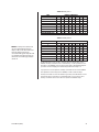
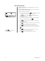
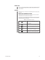
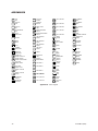
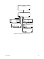
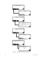
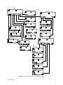
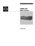
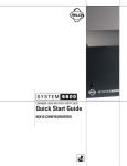
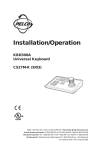
KBD960/KBR960
Desktop Intelligent
Keyboard/M
Installation/
Operation Manual
C1519M-C (8/05)
Pelco World Headquarters • 3500 Pelco Way, Clovis, CA 93612-5699 USA • www.pelco.com
USA & Canada: Tel: 800/289-9100 • Fax: 800/289-9150
International: Tel: 1-559/292-1981 • Fax: 1-559/348-1120
CONTENTS
Section
Page
REGULATORY NOTICES .................................................................................. 6
IMPORTANT SAFEGUARDS AND WARNINGS ............................................... 7
DESCRIPTION .................................................................................................. 8
MODELS .................................................................................................... 8
READING THIS MANUAL ......................................................................... 8
KEYBOARD LAYOUT ................................................................................ 9
LCD DISPLAY .................................................................................... 9
ICON KEYS ....................................................................................... 9
KEYPAD ............................................................................................. 9
FUNCTION KEYS .............................................................................. 9
CONTROL KEYS .............................................................................. 10
LENS KEYS ...................................................................................... 10
JOYSTICK ........................................................................................ 10
TURBO KEY ..................................................................................... 10
ESCAPE KEY ................................................................................... 10
INSTALLATION ................................................................................................. 11
CONNECTING TO THE CM6800 ............................................................. 11
SETUP MODE .......................................................................................... 12
ACTIVATING SETUP MODE ............................................................ 12
CALIBRATING THE JOYSTICK ....................................................... 12
CREATING A SETUP PIN ................................................................. 13
CREATING A DEFINE PIN ............................................................... 13
ADJUSTING THE DISPLAY BRIGHTNESS ..................................... 14
CONFIGURING THE COM PORTS ................................................. 14
DEFAULT SETTINGS ............................................................... 14
CONFIGURING THE FUNCTION KEYS .......................................... 15
EXITING SETUP MODE ................................................................... 15
OPERATION ..................................................................................................... 16
LOGGING ON ........................................................................................... 16
LOGGING OFF ......................................................................................... 16
ACCESSING THE KBD960 MENUS ........................................................ 17
SENDING/RECEIVING KEYBOARD SETUPS ................................ 25
ACCESSING THE CM6800 MAIN PROGRAMMING MENU ................... 26
DIAGNOSTIC MODE ................................................................................ 27
TESTING THE DISPLAY .................................................................. 27
TESTING THE KEYBOARD ............................................................. 27
TESTING THE SERIAL PORTS ....................................................... 27
TESTING THE DIP SWITCHES ....................................................... 27
SELECTING MONITORS ......................................................................... 28
MAIN MENU 1 .................................................................................. 28
MONITOR MENU ............................................................................. 28
FUNCTION KEY ............................................................................... 28
SELECTING CAMERAS ........................................................................... 28
MAIN MENU 1 .................................................................................. 28
CAMERA MENU ............................................................................... 28
FUNCTION KEY ............................................................................... 28
OPERATING PTZ CAMERAS .................................................................. 29
2
C1519M-C (8/05)
ADVANCED OPERATION ................................................................................ 30
PRESETS ................................................................................................. 30
CREATING PRESETS ...................................................................... 30
RECALLING PRESETS .................................................................... 30
DELETING PRESETS ...................................................................... 30
PATTERNS ............................................................................................... 31
CREATING PATTERNS .................................................................... 31
PATTERN LENGTH .......................................................................... 32
STARTING PATTERNS .................................................................... 32
STOPPING PATTERNS .................................................................... 32
ZONES ...................................................................................................... 33
RULES TO FOLLOW WHEN CREATING ZONES ........................... 33
CREATING ZONES .......................................................................... 34
PARTIAL ZONE OVERLAP .............................................................. 35
EMBEDDED ZONES ........................................................................ 36
TURNING ZONES ON AND OFF ..................................................... 36
ERASING ZONES ............................................................................ 36
MACROS .................................................................................................. 37
STARTING MACROS ....................................................................... 37
STOPPING MACROS ....................................................................... 37
PAUSING MACROS ......................................................................... 37
SEQUENCE .............................................................................................. 38
STARTING SEQUENCES ................................................................ 38
STOPPING SEQUENCES ................................................................ 38
PAUSING SEQUENCES .................................................................. 38
OPERATING RELAYS .............................................................................. 39
ACTIVATING RELAYS USING F12 .................................................. 39
ACTIVATING RELAYS FROM THE GPI MENUS ............................. 39
MOMENTARY ........................................................................... 39
LATCHING ................................................................................ 39
MULTIPLEXER CONTROL ....................................................................... 41
VIDEO LOSS ............................................................................................ 42
ALARMS ................................................................................................... 42
RESETTING TRIGGERED ALARMS ............................................... 42
APPENDICES ................................................................................................... 43
SPECIFICATIONS ............................................................................................ 47
C1519M-C (8/05)
3
LIST OF ILLUSTRATIONS
Figure
1
2
3
4
5
6
7
8
9
10
11
12
13
14
15
16
17
18
19
20
21
22
23
24
25
26
27
28
29
30
31
32
33
34
35
36
37
38
39
40
41
42
43
4
Page
KBD960/KBR960 ................................................................................. 9
Connecting to the CM6800 ................................................................ 11
Enter Setup PIN ................................................................................. 12
Setup Mode ....................................................................................... 12
Joystick Setup .................................................................................... 12
Advance Setup 2 ............................................................................... 13
LCD Brightness Setup ....................................................................... 14
Advance Setup 1 ............................................................................... 14
Key Define Mode ............................................................................... 15
Logon Screen .................................................................................... 16
Logoff Screen ..................................................................................... 16
Main Menu 1 ...................................................................................... 17
Main Menu 2 ...................................................................................... 17
Monitor Menu ..................................................................................... 18
Camera Menu 1 ................................................................................. 18
Camera Menu 2 ................................................................................. 19
MUX Menu 1 ...................................................................................... 19
MUX Menu 2 ...................................................................................... 20
Alarm Menu ....................................................................................... 20
GPI Menu 1 ........................................................................................ 21
GPI Menu 2 ........................................................................................ 21
Preset Menu ...................................................................................... 22
Macro Menu ....................................................................................... 22
Sequence Menu ................................................................................. 23
Define Menu 1 ................................................................................... 23
Define Menu 2 ................................................................................... 23
Define Preset Menu ........................................................................... 24
Define Zone Menu ............................................................................. 24
Setup LCD Menu ............................................................................... 24
Programming Menu ........................................................................... 24
Database Menu ................................................................................. 25
Password Screen ............................................................................... 26
Main Programming Menu .................................................................. 26
Diagnostic Mode Menu ...................................................................... 27
LCD Test ............................................................................................ 27
Keyboard Test .................................................................................... 27
SIO Test ............................................................................................. 28
DIP Switch Test .................................................................................. 28
Pattern Definitions ............................................................................. 32
Basic Zone Creation .......................................................................... 35
Partial Zone Overlap .......................................................................... 36
Embedded Zones .............................................................................. 37
MUX Control Menu ............................................................................ 42
C1519M-C (8/05)
LIST OF TABLES
Table
A
B
C
D
E
F
G
H
I
J
K
L
M
N
O
Q
R
S
U
V
W
X
Y
Page
Function Key Defaults .......................................................................... 15
Main Menu 1 ........................................................................................ 17
Main Menu 2 ........................................................................................ 17
Monitor Menu ....................................................................................... 18
Camera Menu 1 ................................................................................... 18
Camera Menu 2 ................................................................................... 19
MUX Menu 1 ........................................................................................ 19
MUX Menu 2 ........................................................................................ 20
Alarm Menu .......................................................................................... 20
GPI Menu 1 .......................................................................................... 21
GPI Menu 2 .......................................................................................... 21
Preset Menu ........................................................................................ 22
Macro Menu ......................................................................................... 22
Sequence Menu ................................................................................... 23
Define Menu 1 ..................................................................................... 23
Define Preset Menu ............................................................................. 24
D efine Zone Menu .............................................................................. 24
Setup LCD Menu ................................................................................. 24
Database Menu ................................................................................... 25
Spectra/Esprit Programming Menu ...................................................... 33
Relay Unit 1 ......................................................................................... 41
Relay Unit 2 ......................................................................................... 41
Triggered Alarm Functions ................................................................... 43
LIST OF APPENDICES
Appendix
A
B
C
D
C1519M-C (8/05)
Page
Icons Legend ....................................................................................... 44
Setup Mode Menu Tree (DIP Switch 2 ON) ......................................... 45
Diagnostic Mode Menu Tree (DIP Switch 1 ON) .................................. 46
Operation Mode Menu Tree (DIP Switch 2 OFF) ................................. 47
5
REGULATORY NOTICES
This equipment has been tested and found to comply with the limits of a Class B digital device, pursuant to part 15 of the FCC rules.
These limits are designed to provide reasonable protection against harmful interference in a residential installation. This equipment
generates, uses, and can radiate radio frequency energy and, if not installed and used in accordance with the instructions, may
cause harmful interference to radio communications. However there is no guarantee that the interference will not occur in a particular installation. If this equipment does cause harmful interference to radio or television reception, which can be determined by turning the equipment off and on, the user is encouraged to try and correct the interference by one or more of the following measures:
•
Reorient or relocate the receiving antenna.
•
Increase the separation between the equipment and the receiver.
•
Connect the equipment into an outlet on a circuit different from that to which the receiver is connected.
•
Consult the dealer or an experienced radio/TV technician for help.
6
C1519M-C (8/05)
IMPORTANT SAFEGUARDS AND WARNINGS
1. Read, keep, and follow these instructions.
2. Heed all warnings.
3. There are no user-serviceable parts inside this unit. Only authorized service
personnel may open the unit.
4. Installation and servicing should only be done by qualified service personnel
and conform to all local codes.
5. WARNING: To reduce the risk of fire or electric shock, do not expose this
unit to rain or moisture if this unit is designed for indoor use only.
6. Unless this unit is specifically marked as a NEMA Type 3, 3R, 3S, 4, 4X, 6 or
6P enclosure, it is designed for indoor use only and it must not be installed
where exposed to rain or moisture.
7. Do not expose this unit to dripping or splashing. Do not place objects filled
with liquids, such as vases, on this unit.
8. Do not block any ventilation openings. Install in accordance with the
manufacturer’s instructions.
9. The installation method and materials should be capable of supporting four
times the weight of the unit and equipment.
10. Do not install near any heat source.
11. Only use attachments/accessories specified by the manufacturer.
12. Clean only with dry cloth.
13. Do not defeat the safety purpose of the polarized or grounding-type plug.
14. Protect the power cord from being walked on or pinched, particularly at
plugs, convenience receptacles, and the point where they exit from the unit.
15. Unplug this unit during lightning storms or when unused for long periods of
time.
16. A CCC-approved power cord must be used to power this equipment when
used in China.
The product and/or manual may bear the following marks:
This symbol indicates that dangerous
voltage constituting a risk of electric
shock is present within this unit.
This symbol indicates that there are important operating and maintenance instructions in the literature accompanying
this unit.
CAUTION:
RISK OF ELECTRIC SHOCK.
DO NOT OPEN.
Please thoroughly familiarize yourself with the information in this manual prior to
installation and operation.
FOR QUALIFIED SERVICE PERSONNEL ONLY
1. Only use replacement parts recommended by Pelco.
2.
C1519M-C (8/05)
After replacement/repair of this unit’s electrical components, conduct a resistance measurement between line and exposed parts to verify the exposed
parts have not been connected to line circuitry.
7
DESCRIPTION
The KBD960/KBR960 Keyboard includes Pelco’s proprietary M protocol, allowing it
to be used with all M devices, such as Pelco’s latest matrix switch – the CM6800.
You can program the keyboard, and you can create and execute macros. You have
access to effective monitoring procedures for any CCTV application.
You can assign simple or complex functions to many of the keys. This allows you
to configure the keyboard to suit a specific monitoring environment. Some of the
keyboard features include the following:
•
User-friendly, icon-driven design
•
Select and monitor any connected camera or video input
•
Control pan and tilt functions for cameras and configured receivers
•
Control camera iris (zoom and focus) for configured equipment
•
Control camera auxiliary functions for configured equipment
•
Control peripheral devices, such as video printers, frame stores, and video
multiplexers
•
Select macros to execute complex procedures
•
Store and recall camera presets for equipment with preset capabilities
•
Download function key configurations to and from other keyboards
MODELS
KBD960
Programmable keyboard that can be used with all M devices.
120 VAC, 60 Hz
KBD960-X
Same as the KBD960, except 230 VAC, 50 Hz
KBR960
Same functions as the KBD960 models, except it can be
mounted onto a rack. 120 VAC, 60 Hz
KBR960-X
Same as the KBR960, except 230 VAC, 50 Hz
READING THIS MANUAL
Each icon key corresponds to an icon on the LCD display. Each icon represents
a function.
You will be instructed to “Select [icon]” when reading this manual. Press the icon
key that corresponds to the icon on the LCD.
The functions of the KBR960 and KBR960-X are the same as the KBD960 and
KBD960-X. The only difference is that the KBR960 models can be mounted onto
a rack. Any reference in this manual to the KBD960 also applies to the KBR960
models.
You will read references to the CM6800. However, the M protocol allows this keyboard to be used with other M devices.
8
C1519M-C (8/05)
KEYBOARD LAYOUT
The KBD960 keyboard consists of the following:
1.
2.
3.
4.
5.
6.
7.
8.
9.
LCD Display
Icon Keys
Keypad
Function Keys
Control Keys
Lens Keys
Joystick
Turbo Key
Escape Key
9
2
1
ICON KEYS
LCD DISPLAY
7
ESCAPE KEY
JOYSTICK
8
FUNCTION KEYS
(F1-F24)
4
6
3
KEYPAD
5
TURBO KEY
LENS KEYS
CONTROL KEYS
00891
KBD960
KBR960
Figure 1. KBD960/KBR960
LCD DISPLAY
The LCD is a four-line display. Each line displays different information.
Line 1
Displays the video output (which is typically a monitor) and the video
input source (which is typically a camera).
Line 2
Displays the last number entered and the icon of the current menu.
Line 3
Displays alarm messages and other prompts.
Line 4
Displays the icons for the icon keys.
ICON KEYS
These eight blue keys correspond to the icons directly above on the LCD display.
These icons change depending on the mode you are in.
KEYPAD
The keyboard has a standard numeric keypad with two additional keys for selecting cameras and monitors.
FUNCTION KEYS
The 24 function keys (F1-F24) can be programmed according to your application
and the type of CCTV installation.
Refer to the Installation section for an explanation on how to program these keys.
The supplied blank labels and punched LEXAN® decal overlay should be used.
C1519M-C (8/05)
9
CONTROL KEYS
These keys are used for the following functions:
Step backward through available camera selections.
Step forward through available camera selections.
Select and execute macros.
Rcl: Recall previous selections.
Alt: Reserved for future use.
Prst: Recall preset.
Lock: Reserved for future use.
LENS KEYS
You can use these keys to control cameras equipped with motorized zoom
lenses and motorized pan and tilt units. These keys are sometimes used to activate other functions. For example, the Open/Close key is also used when creating preset labels.
Zoom in/out.
Focus near/far.
Open/close the iris.
JOYSTICK
The proportional joystick allows variable speed control. It gives you full control
over the pan and tilt movements, from minimum to maximum speed. You should
calibrate the joystick before setting up anything else.
TURBO KEY
Pressing this key while moving the joystick switches pan motors into high-speed
mode on equipment that is capable of panning.
ESCAPE KEY
This key exits you from the mode you are in.
10
C1519M-C (8/05)
INSTALLATION
The following items are supplied:
•
•
•
•
KBD960/KBR960 Keyboard
CM9505UPS Universal Power Supply
Two 25 ft (7.6 m) straight RJ-45 cables (one with ferrite)
10 blank labels and 10 punched LEXAN decal overlays
CONNECTING TO THE CM6800
NOTE: Communication to the
keyboards is RS-485. Pelco recommends using four-conductor, shielded,
18-gauge twisted pairs, such as
Belden 9418, or a similar cable that
meets or exceeds the basic requirements for EIA RS-485 applications.
1.
Set all DIP switches OFF. The DIP switches are located on the bottom of the
keyboard.
2.
Connect the RJ-45 straight cable with ferrite from COM 1 of the keyboard to
the CM9505UPS power supply. The ferrite end of the cable must go into the
keyboard. See Figure 2.
3.
Connect the other RJ-45 straight cable from the power supply to COM 3 of
the CM6800.
4.
Plug the power supply into a 120 VAC power source.
MAIN PORT USED FOR POWER INTO KEYBOARD, AND FOR
COMMUNICATION LINK TO PELCO 6800. THESE I/O LINES ARE
CONNECTED TO 8-PIN RJ SOCKET JP1 AS SHOWN BELOW.
INCOMING DC IS ALSO BROUGHT IN VIA THIS COM PORT.
VOLUME
8
COM 1
JP1 PIN
FUNCTION
JP1 PIN
FUNCTION
1
RS-485 Tx+
5
GND (0 VDC IN)
2
RS-485 Tx-
6
—
3
—
7
RS-485 Rx-
4
+12 VDC IN
8
RS-485 R+
DIP SWITCHES
RESET
BUTTON
RS-485 SERIAL PORT
00893
ALARM
1 2 3 4 5 6 7 8
COM
16
1
5
2
6
3
7
CONTROL
31
3
32
4
4
8
PTZ
A T T
+ -
R R T T
- + + -
R R B
- +
OUT
1
2
F
3
COM 1
6
7
COM 3 DEFAULT SETTINGS:
M, RS-485, 19200 BAUD,
NO PARITY, 8 DATA BITS,
1 STOP BIT
8
120/230~
50/60 HZ
25 WATTS
VIDEO OUTPUTS
STRAIGHT CABLE
(SUPPLIED)
CM6800 COM 3
RJ-45 PIN-OUTS
1
2
3
4
5
6
7
8
Rx+
RxNC
NC
GROUND
NC
TxTx+
KBD960
RJ-45 PIN-OUTS
1
2
3
4
5
6
7
8
RS-485
CM9505UPS
UNIVERSAL POWER SUPPLY
Tx+
Tx-
STRAIGHT CABLE WITH FERRITE
(SUPPLIED)
RxRx+
KBD960
Figure 2. Connecting to the CM6800
C1519M-C (8/05)
11
SETUP MODE
You can configure the KBD960 in the Setup Mode. You can do the following:
•
•
•
•
•
•
•
Create a Personal Identification Number (PIN) for entering the Setup Mode.
Create a PIN that provides access to features on the Define Menu.
Calibrate the joystick.
Adjust the display brightness.
Set the data transmission speeds for the keyboard’s three COM ports.
Define the function keys.
Select a host port.
The default setup PIN is 1234. You can change it in the Setup Mode.
ACTIVATING SETUP MODE
1.
Set DIP Switch 2 ON. “ENTER SETUP PIN” appears.
2.
Enter your PIN number (the default number is 1234) and “SETUP MODE”
appears.
ENTER SETUP PIN
00895
Figure 3. Enter Setup PIN
SETUP MODE vX.XX
JSTK
LCD
ADV
Figure 4. Setup Mode
00896
CALIBRATING THE JOYSTICK
JOYSTICK SETUP
xxx
xxx
(xxx, xxx)
xxx
xxx
00897
1.
Select
2.
Select
3.
Move the joystick completely to the left and select
4.
Move the joystick completely to the right and select
5.
Move the joystick completely down and select
6.
Move the joystick completely up and select
7.
Select
to save the joystick configuration.
8.
Select
to return to the Setup Menu.
JSTK
from Setup Mode. “JOYSTICK SETUP” appears on the LCD.
with the joystick in the center default position.
.
Figure 5. Joystick Setup
.
.
.
RESTORING FACTORY DEFAULT SETTINGS
1.
2.
Set DIP switches 1, 2, and 8 ON and recycle power.
Re-calibrate the joystick if using a keyboard version before 1.20.
For version 1.20 and later keyboards, the joystick is automatically calibrated
during a factory default initialization.
12
C1519M-C (8/05)
CREATING A SETUP PIN
Advance Setup 2
Setup Pin!
Confirm!
Define Pin!
Confirm!
****
****
****
****
The factory settings for the KBD960 include the default setup PIN 1234.
Follow these steps to change the default PIN:
DEF
NUM
from Setup Mode.
1.
Select
2.
Select
and/or
to locate Advance Setup 2.
3.
Select
and/or
to choose Setup PIN.
4.
Select
5.
Advance the cursor to the confirm row, select
ADV
00898
Figure 6. Advance Setup 2
select
6.
DEF
NUM
DEF
NUM
Select
, enter a four-digit PIN, and select
DEF
NUM
DEF
NUM
once again.
, re-enter your PIN, and
once again. The menu indicates “OK” if confirmed.
to save your PIN.
CREATING A DEFINE PIN
You also need a PIN to access the extended keyboard functions that are available in the Define Menu. The default define PIN is also 1234. Follow these steps
to change it (refer to Figure 6):
Select
2.
Select
and/or
to locate Advance Setup 2.
3.
Select
and/or
to choose Define PIN.
4.
Select
5.
Advance the cursor to the confirm row, select
select
6.
C1519M-C (8/05)
from Setup Mode.
1.
Select
ADV
DEF
NUM
DEF
NUM
, enter a four-digit PIN, and select
DEF
NUM
DEF
NUM
once again.
, re-enter your PIN, and
once again. The menu indicates “OK” if confirmed.
to save your PIN.
13
ADJUSTING THE DISPLAY BRIGHTNESS
LCD BRIGHTNESS SETUP
00899
LCD
1.
Select
from Setup Mode.
2.
Select
to make the display brighter or
3.
Select
and then
to make the display dimmer.
Figure 7. LCD Brightness Setup
.
You can also adjust the display brightness by selecting
LCD
from the Define Menu.
Refer to the Operation section of this manual.
CONFIGURING THE COM PORTS
Advance Setup 1
COM1!!!
COM2!!!
COM3!!!
Local Address!!
None (Host)
None
None
1
1.
Select
2.
Select
and/or
to navigate to the COM 1 row.
3.
Select
and/or
to assign a baud rate.
4.
Select
to set parity for the communications port.
5.
Select
to set the Host.
6.
Select
and/or
to navigate to the Local Address row.
7.
Select
and/or
to assign an address.
Select
to save your configuration and then select
ADV
from Setup Mode and scroll to the Advance Setup 1 screen.
00900
Figure 8. Advance Setup 1
NOTE: COM 2 is functional, but only
COM 1 is optimized for the protocol.
COM 3 is not used for normal
operation.
NOTE: Pelco recommends that you
reserve addresses 1-8 for the
KBD960/KBR960 keyboards. In
System 6800, you should not use an
address higher than 8.
14
8.
to return to
the Setup Mode.
Default Settings
•
•
COM 1 – 19200 baud, No Parity, Set as HOST
Address – 1
C1519M-C (8/05)
CONFIGURING THE FUNCTION KEYS
1.
Select
2.
Press a function key you want to configure. If the key is already defined, its
assigned function is shown. If not, “Def = NOT DEFINED” appears on the
LCD screen.
3.
Select
and/or
NOTE: Refer to Table A for the factory
default settings.
4.
Select
to choose a function.
NOTE: Many of the functions do not
5.
Select
DEF
NUM
and enter the define number.
require that you enter a define
number. In those cases, skip steps 5
and 6.
6.
Select
DEF
NUM
.
7.
Select
NOT DEFINED
NUMx
ESC
BKSPACE
ENTER
DEFINE
KEY DEFINE
from Setup Mode to switch to the key define mode.
PLEASE ENTER A KEY
DEF
NUM
00901
Figure 9. Key Define Mode
and then
to scroll through the list of available functions.
.
Table A. Function Key Defaults
NOTE: In the GPI Menu, F1-F8 are
associated with the external relays in
the current GPI.
Function Key
Default Function
F1
Camera Auxiliary 1
F2
Camera Auxiliary 2
F3
Camera Auxiliary 3
F4
Camera Auxiliary 4
F5
Camera Auxiliary 5
F6
Camera Auxiliary 6
F7
Camera Auxiliary 7
F8
Camera Auxiliary 8
F9
Camera Pattern 1
F10
Camera Pattern 2
F11
Camera Pattern 3
F12
External Relay 1
F13
Multiplexer
F14
Alarm Menu
F15
Macro Menu
F16
Sequence Menu
F17
GPI Menu
F18
Define Menu
F19
Menu Forward
F20
Menu Backward
F21
Backspace
F22
Enter
F23
Clear
F24
—
EXITING SETUP MODE
C1519M-C (8/05)
1.
Select
2.
Set DIP switch 2 OFF.
.
15
OPERATION
This section describes the operation of a CM6800 System using the KBD960
keyboard. Before you begin operating the KBD960, make sure you have completed the following:
1.
Connections have been made and initial power-up has been completed.
2.
CM6800 setup files have been programmed.
3.
PINs have been set up to allow logging on, access to the setup functions,
and access to the Define Menu.
You must also have the following information:
•
•
•
•
•
•
The logical camera number list, complete with identification names
The logical monitor number list, complete with identification names
A list of all macros
A list of all peripheral devices connected
A list of alarms connected to the system
A list of presets for each relevant camera
LOGGING ON
KEYBOARD 960 vX.XX
1.
Set all DIP switches OFF.
2.
Enter the monitor number and press
.
Enter Monitor
00902
Figure 10. Logon Screen
LOGGING OFF
1
1
Logoff?
YES
NO
1.
Select
.
2.
Select
LOG
OFF
.
3.
Select
YES
.
00903
Figure 11. Logoff Screen
The keyboard goes offline for a short while before returning to the “KEYBOARD
960” display.
16
C1519M-C (8/05)
ACCESSING THE KBD960 MENUS
1.
Set DIP switch 2 OFF.
2.
Enter the number of the monitor and then press
3.
Press
.
and the Main Menu 1 icons appear.
Table B. Main Menu 1
1
MAIN MENU 1
1
Select to bring up the Monitor Menu. If you enter a number before
selecting this icon, the monitor number changes to that number.
MUX
GPI
PRST
LOG
OFF
Select to bring up the Camera Menu. If you enter a number before selecting this icon, the camera number changes and the
camera switches on the current monitor without going into the
Camera Menu.
00904
Figure 12. Main Menu 1
MUX
Select to bring up the MUX Menu. You can enter a number before selecting this icon. If you enter a number before selecting
this icon, the multiplexer number changes and the system
switches to that multiplexer without going into the MUX Menu.
When an alarm is triggered, this icon appears on the keyboard
screen. The current alarm shown on the user monitor is the
alarm that appears when the Alarm Menu is selected.
GPI
Select to bring up the GPI Menu. If you enter a GPI number before selecting this icon, control and data information are requested for the selected GPI.
PRST
Select to bring up the Preset Menu. If you enter a number before
selecting this icon, the preset is called without the Preset Menu
being displayed.
Select to bring up the next page (Main Menu 2).
LOG
OFF
Select to log off the system.
Table C. Main Menu 2
1
MAC
SEQ
MAIN MENU 2
1
MAC
Select to bring up the Macro Menu. If you enter a macro number
before selecting this icon, the selected macro plays without having to go into the Macro Menu.
SEQ
Select to bring up the Sequence Menu. If you enter a sequence
number before selecting this icon, the selected sequence plays
without going into the Sequence Menu.
DEF
00905
Figure 13. Main Menu 2
Select to bring up Define Menu 1. You will see
PIN
and
LCD
.
Enter your define PIN. You will not have to re-enter your define
DEF
PIN unless the keyboard goes offline or you log off. When you
enter your PIN, Define Menu 2 appears. You will also see
LCD
in Define Menu 2. You can adjust the display brightness in Define Menu 1 or Define Menu 2.
or
C1519M-C (8/05)
Selecting either one returns you to Main Menu 1.
17
Table D. Monitor Menu
1
MONITOR MENU
1
Select to request the previous logical monitor number in the system and to grant control of the monitor if it is available. The logical monitor number range is 1-9999.
Select to request the next logical monitor number in the system
and to grant control of the monitor if it is available. The logical
monitor number range is 1-9999.
00906
Figure 14. Monitor Menu
This icon indicates whether or not you have control of the monitor.
A highlighted icon means you have control. Select this icon to request or release control of the selected monitor. If you enter a
number before selecting this icon, the keyboard requests control
of that monitor.
Reserved for future use.
Select this icon to return to Main Menu 1.
Table E. Camera Menu 1
1
CAMERA MENU 1
1
Select to request the previous logical camera number in the
system and grant control if it is available.
1
Select to request the next logical camera number in the system
and grant control if it is available.
2
00907
Figure 15. Camera Menu 1
Select to run a selected pattern.
This icon shows whether or not you have control of the selected
camera. A highlighted icon means you have control. Select this
icon to request or release control of the selected camera. If you
enter a number before selecting this icon, the keyboard requests
control of that camera.
1
Select to send an AUX 1 set command to the selected camera.
When you release the key, a clear command is sent.
2
Select to send an AUX 2 set command to the selected camera.
When you release the key, a clear command is sent.
Select to bring up Camera Menu 2.
Select to return to Main Menu 1.
18
C1519M-C (8/05)
Table F. Camera Menu 2
1
1
3
4
5
6
7
CAMERA MENU 2
3
Select to send an AUX 3 set command to the selected camera.
When you release the key, a clear command is sent.
4
Select to send an AUX 4 set command to the selected camera.
When you release the key, a clear command is sent.
5
Select to send an AUX 5 set command to the selected camera.
When you release the key, a clear command is sent.
6
Select to send an AUX 6 set command to the selected camera.
When you release the key, a clear command is sent.
7
Select to send an AUX 7 set command to the selected camera.
When you release the key, a clear command is sent.
8
Select to send an AUX 8 set command to the selected camera.
When you release the key, a clear command is sent.
or
Select to return to Camera Menu 1.
8
00908
Figure 16. Camera Menu 2
Table G. MUX Menu 1
1
MUX MENU 1
1
Select to request the previous logical multiplexer number in the
system and grant control of the multiplexer if it is available.
MUX
MUX
Select to request the next logical multiplexer number in the system and grant control of the multiplexer if it is available.
00909
Figure 17. MUX Menu 1
MUX
This icon shows whether or not you have control of the selected multiplexer. A highlighted icon means you have control.
Select this icon to either request or release control of the selected multiplexer. If you enter a number before selecting this
icon, the keyboard requests control of that multiplexer.
Select to send a MUX TAPE command to the selected multiplexer.
Select to send a MUX LIVE command to the selected multiplexer.
Select to send a MUX ZOOM command to the selected multiplexer. If you enter a number before selecting this icon, the
command sent to the multiplexer becomes a MUX SWITCH
CHANNEL command to the specified channel.
Select to bring up MUX Menu 2.
Select to return to Main Menu 1.
C1519M-C (8/05)
19
Table H. MUX Menu 2
1
MUX MENU 2
1
MUX
Select to send a MUX PIP command to the selected multiplexer.
00910
Figure 18. MUX Menu 2
Select to send a MUX 4-camera command to the selected
multiplexer.
Select to send a MUX 9-camera command to the selected multiplexer.
Select to send a MUX 16-camera command to the selected multiplexer.
Select to bring up MUX Menu 1.
Select to return to Main Menu 1.
Table I. Alarm Menu
1
ALARM MENU
1
Select to request the previous triggered logical alarm number in
the system. The CM6800 matrix interprets this command as a
Previous Alarm Step.
00911
Figure 19. Alarm Menu
Select to request the next triggered logical alarm number in the
system. The CM6800 matrix interprets this command as a Next
Alarm Step.
Select to turn off the alarm siren of the keyboard.
Select to send an ALARM RESET command for the currently
displayed alarm.
Select to send an ALARM RESET ALL command. The CM6800
matrix interprets this command as a Reset Current Alarm on all
monitors.
Select to pause an alarm that has been triggered.
Select to return to Main Menu 1.
20
C1519M-C (8/05)
Table J. GPI Menu 1
1
GPI MENU 1
1
GPI
GPI
GPI
MTRY
1
2
3
4
00912
Figure 20. GPI Menu 1
MTRY
Select to set the current GPI to the input value. Select to request control of the selected GPI and send a message to gather
information about the status of the auxiliaries within the GPI.
You have control if this icon is highlighted.
If this icon is highlighted, the auxiliary control method is momentary. If it is not highlighted, the auxiliary control method is latching.
In momentary mode, selecting the icon sends an AUX ON command and releasing the key sends an AUX OFF command. The
latching mode disables the AUX OFF command from being sent
when the key is released. In latching mode, you can specify a
number up to 6553 and then press the auxiliary number to set the
auxiliary and have it unlatch at the specified time (1-6553 in seconds). If you do not enter a number, the auxiliary latches until an
AUX OFF command is sent. You can issue an AUX OFF command by placing the keyboard in MTRY (momentary) mode again
and pressing the key (when the key is released an AUX OFF is
sent and the AUX ON when pressing the key is ignored).
1
Select to send a set auxiliary command for the auxiliary within
the selected GPI. Pressing the key sends an AUX ON and
releasing it sends an AUX OFF in momentary mode.
2
Select to send a set auxiliary command for the auxiliary within
the selected GPI. Pressing the key sends an AUX ON and
releasing it sends an AUX OFF in momentary mode.
3
Select to send a set auxiliary command for the auxiliary within
the selected GPI. Pressing the key sends an AUX ON and
releasing it sends an AUX OFF in momentary mode.
4
Select to send a set auxiliary command for the auxiliary within
the selected GPI. Pressing the key sends an AUX ON and
releasing it sends an AUX OFF in momentary mode.
Select to bring up GPI Menu 2.
Select to return to Main Menu 1.
Table K. GPI Menu 2
1
GPI MENU 2
1
5
Select to send a set auxiliary command for the auxiliary within
the selected GPI. Pressing the key sends an AUX ON and
releasing it sends an AUX OFF in momentary mode
6
Select to send a set auxiliary command for the auxiliary within
the selected GPI. Pressing the key sends an AUX ON and
releasing it sends an AUX OFF in momentary mode.
7
Select to send a set auxiliary command for the auxiliary within
the selected GPI. Pressing the key sends an AUX ON and
releasing it sends an AUX OFF in momentary mode.
8
Select to send a set auxiliary command for the auxiliary within
the selected GPI. Pressing the key sends an AUX ON and
releasing it sends an AUX OFF in momentary mode.
GPI
5
6
7
8
00913
Figure 21. GPI Menu 2
Select to return to GPI Menu 1.
Select to return to Main Menu 1.
C1519M-C (8/05)
21
Table L. Preset Menu
1
PRESET MENU
1
PRST
PRST
Select to send a PRESET CALL command to the current camera.
Select to send a PATTERN START command to the current
camera. You can enter a number to initiate a specific pattern.
PRST
00914
Figure 22. Preset Menu
Select to send a ZONE SCAN ON command to the current
camera and display the “Zone On” text. When this text is
displayed, you can select this icon again to send a ZONE SCAN
OFF command, which displays the “Zone Off” text.
Select to return to Main Menu 1.
Table M. Macro Menu
1
MACRO MENU
1
Select to request the previous logical macro number in the
system and grant control of the macro if it is available.
MAC
MAC
Select to request the next logical macro number in the system
and grant control of the macro if it is available.
00915
Figure 23. Macro Menu
MAC
This icon shows whether or not the user has control of the
selected macro. If the icon is highlighted, you have control.
Select this icon to either request or release control of the
selected macro. If you enter a number before selecting this icon,
the keyboard requests control of that macro.
Select to start or stop a macro.
Select to start or stop a macro.
Select to send a stop command to the selected macro.
Select to send a MACRO PAUSE command to the selected
macro.
Select to return to Main Menu 1.
22
C1519M-C (8/05)
Table N. Sequence Menu
1
SEQUENCE MENU
1
Select to request the previous logical sequence number in the
system and grant control of the sequence if it is available.
SEQ
SEQ
Select to request the next logical sequence number in the
system and grant control of the sequence if it is available.
00916
Figure 24. Sequence Menu
SEQ
This icon shows whether or not you have control of the selected
sequence. If the sequence is highlighted, you have control.
Select this icon to request or release control of the selected
sequence. If you enter a number before selecting this icon,
the keyboard will request control of that sequence number.
Select to send a SEQ PLAY BWD command to the selected
sequence.
Select to send a SEQ PLAY FWD command to the selected
sequence.
Reserved for future use.
Reserved for future use.
Select to return to Main Menu 1.
Table O. Define Menu 1
1
DEFINE MENU 1
1
PIN
Enter your PIN to bring up Define Menu 2. Define Menu 2
appears automatically if you have already entered your PIN.
You will not have to re-enter your PIN unless the keyboard goes
offline or you log off.
LCD
Select to adjust the LCD display brightness.
PIN
LCD
PIN
00917
Figure 25. Define Menu 1
Table P. Define Menu 2
1
DEFINE MENU 2
1
DEF
PRST
PRST
LCD
Select to enter the Define Preset Menu.
MENU
Select to enter the Define Zone Menu.
00918
Figure 26. Define Menu 2
LCD
Select to enter the Setup LCD Menu.
Select to send a start pattern programming command to the
current camera. A highlighted pattern symbol appears. Selecting
pattern again stops the command and the pattern symbol becomes normal.
MENU
Select to bring up the Programming Menu.
Select to bring up the Database Menu.
Select to return to Main Menu 1.
C1519M-C (8/05)
23
Table Q. Define Preset Menu
1
DEFINE PRESET MENU
1
DEF
PRST
PRST
DEL
PRST
00919
Figure 27. Define Preset Menu
DEL
Select to send a set preset command and a preset label to the
current camera. A preset number is required prior to selecting
this icon.
Reserved for future use.
Select to return to the Define Menu.
Table R. D efine Zone Menu
1
DEFINE ZONE MENU
1
DEF
Select to send a set zone command to the current camera.
Select to return to the Define Menu.
00920
Figure 28. Define Zone Menu
Table S. Setup LCD Menu
1
SETUP LCD MENU
1
LCD
Select to make the display brighter.
Select to make the display dimmer.
00921
Figure 29. Setup LCD Menu
Select to save your settings.
Select to return to the Define Menu.
Table T. Programming Menu
1
DEF
PROGRAMMING MENU
1
MENU
Select to send a MENU ITEM DOWN command to the system
master.
PGM
00922
Select to send a MENU ITEM UP command to the system master.
Figure 30. Programming Menu
Select to send a MENU ITEM LEFT command to the system
master.
Select to send a MENU ITEM RIGHT command to the system
master.
Select to increase the current item.
Select to decrease the current item. Enter a number and select
this icon to set the editing field.
PGM
Select to display the program menu on your monitor.
Select to return to the Define Menu.
24
C1519M-C (8/05)
Table U. Database Menu
DATABASE MENU
Select to send the keyboard’s key configuration to another
keyboard. You must enter the local device address of the
second keyboard. This is only sent to a device on the same bus
as the keyboard.
DEF
00923
Figure 31. Database Menu
Select to receive another keyboard’s key configuration database.
You must enter the local device address of the second keyboard.
This is only sent to a device on the same bus as the keyboard.
Select to return to the Define Menu.
SENDING/RECEIVING KEYBOARD SETUPS
You can set up only one KBD960 keyboard and send the information to another
keyboard. You can also receive the setup information from a connected keyboard.
The COM ports are located on the bottom of the keyboard.
NOTE: COM 3 is RS-232 and is
Follow these steps to send or receive setup information between keyboards:
only used for sending/receiving
settings between keyboards. It is not
used for normal operation.
1.
Select
from Define Menu 2 to bring up the Database Menu. See Figure 31.
2.
Select
to send setup information to a connected keyboard.
NOTE: To send/receive setup
information, all KBD960 keyboards
must be connected to the M bus.
However, each keyboard must have a
unique local M device address.
“Sending Data” appears on the LCD. “Key Data Sent” appears on the LCD
when the transfer is complete.
or
Select
to receive setup information from a connected keyboard.
“Receiving KeyDefs” appears on the LCD. “Keys Uploaded” appears on the
LCD when the transfer is complete.
C1519M-C (8/05)
25
ACCESSING THE CM6800 MAIN PROGRAMMING MENU
1.
Select
2.
Enter your Define PIN.
3.
Select
4.
Select
DEF
.
MENU .
PGM
. The following screen appears on your monitor.
PELCO VIDEO SWITCHER
MODEL CM6800
PASSWORD TO MAIN MENU
*******
SCRATCHPAD SEQUENCE
RETURN
00619
Figure 32. Password Screen
5.
Enter your password (default is 2899100). The Main Programming Menu
appears.
!
!
!
!
!
!
!
!
!
!
!
!
!
!
!
!
!
PELCO SWITCHER
MODEL CM6800
MAIN MENU
1!
2!
3!
4!
5!
6!
7!
8!
9!
10!
11!
12!
13!
14!
CAMERA
LOGICAL CAMERA
MONITOR
ACCESS
TIME & DATE
PORT
PRIORITY
SEQUENCE
MACRO
ALARM CONTACTS
EVENT TIMER
SET AUXILIARY MENU
SET PASSWORD
ABOUT CM6800
!
ENGLISH
!
RETURN
00924
Figure 33. Main Programming Menu
Refer to the CM6800 Installation/Operation Manual (C1515M) for detailed instructions on setting the various items on the Main Programming Menu.
26
C1519M-C (8/05)
DIAGNOSTIC MODE
To activate the Diagnostic Mode set DIP switch 1 ON. This mode allows the following tests:
DIAGNOSTIC MODE vX.XX
00925
Figure 34. Diagnostic Mode Menu
•
•
•
•
LCD test
Keyboard test
Serial Input/Output (SIO) test
DIP Switch test
TESTING THE DISPLAY
LCD TEST
G0
G1
G2
1.
Select
while in the Diagnostic Mode.
2.
Select
G0
to test graphic page 0.
3.
Select
G1
to test graphic page 1.
4.
Select
G2
to test graphic page 2.
5.
Select
T0
to test the text page.
6.
Select
T0
00926
Figure 35. LCD Test
.
TESTING THE KEYBOARD
KEYBOARD TEST vX.XX
PLEASE ENTER A KEY
Joystick Position – (xxx, xxx)
00927
Figure 36. Keyboard Test
NOTE: Version 1.20 and later
displays three joystick positions (xxx,
xxx, xxx).
C1519M-C (8/05)
NOTE: If the software running on the KBD960 is v1.20 or later, then DIP switch 3
is used to indicate whether or not the software is taking A-to-D readings from the
zoom axis of the joystick. If DIP switch 3 is OFF, you should see three readings
(xxx, xxx, xxx) on the keyboard test screen. If the zoom A-to-D reading (the third
reading) changes as you move the zoom top, DIP switch 3 should be OFF. If the
zoom A-to-D reading does not change as you move the zoom top, DIP switch 3
should be ON.
1.
Select
.
2.
Press each key to ensure that the display shows the correct key.
3.
Select
.
27
TESTING THE SERIAL PORTS
SIO TEST
COM1
COM2
This test is reserved for factory use only.
COM3
00928
Figure 37. SIO Test
TESTING THE DIP SWITCHES
DIPSWITCH TEST
00000001
1.
Select
2.
Beginning with switch 2, set each switch ON while observing the display.
.
00929
Figure 38. DIP Switch Test
28
C1519M-C (8/05)
SELECTING MONITORS
You can select up to eight monitors. There are several ways you can select monitors.
MAIN MENU 1
1.
Enter the monitor number (1-8).
2.
Press
or select
.
The monitor number appears next to
on the keyboard LCD.
MONITOR MENU
1.
Select
from Main Menu 1.
2.
Cycle through the available monitors using
You can also enter a monitor number and press
NOTE: F22 is the “enter” default, but
FUNCTION KEY
you can assign this function to one of
the other function keys.
Follow these steps to select a monitor using F22:
1. Press
and/or
.
or select
.
.
2. Enter a monitor number.
3. Press F22.
SELECTING CAMERAS
There are also several ways you can select cameras.
MAIN MENU 1
1.
Enter a logical camera number (1-9999).
2.
Press
or select
. The camera number appears next to
on the keyboard LCD.
CAMERA MENU
1.
Select
from Main Menu 1.
2.
Cycle through the available cameras using
You can also enter a camera number and press
NOTE: F22 is the “enter” default, but
you can assign this function to one of
the other function keys.
and/or
or select
.
.
FUNCTION KEY
Follow these steps to select a camera using F22:
1. Press
.
2. Enter a camera number.
3. Press F22.
You can also use
C1519M-C (8/05)
and
to cycle through cameras.
29
OPERATING PTZ CAMERAS
The controls for PTZ cameras are located on the right-hand side of the keyboard.
The proportional joystick allows variable speed drives. It gives you full control
over the pan and tilt movements, from minimum to maximum speed. Speed is
proportional to the amount by which you move the joystick from its center location.
Press
while moving the joystick to enable high speed operation.
The joystick only provides directional control when a fixed speed PTZ camera is
installed.
The various functions of a PTZ camera can be controlled as follows:
30
1.
To zoom in or out, use
2.
To focus near or far, use
3.
To open or close the iris, use
.
.
.
C1519M-C (8/05)
ADVANCED OPERATION
PRESETS
NOTE: Presets are only possible
when receivers or pan/tilt units have
preset capability.
A preset camera position is a set of parameters which define pan, tilt, zoom, and
focus adjustments. There are four ways you can recall a preset camera position:
•
•
•
•
Manually using the keyboard
Automatically as the result of an alarm condition
From a macro command
From a sequence command
CREATING PRESETS
There are 64 available presets. For example, follow these steps to create Preset 1:
1.
Move the joystick to the desired position.
NOTE: You are asked for your PIN
2.
Select
DEF
only when you access the Define
Menu for the first time after logon.
3.
Select
PRST
4.
Enter 1 and select
from Main Menu 2. Refer to Table C.
to bring up the Preset Menu.
PRST
. “PROGRAMMING PRESET 01 ENTER PRESET
LABEL” appears on the monitor.
5.
Press
to scroll through the alphanumeric characters. Each preset
label can have up to 20 characters. Move the joystick to the right to set each
character.
6.
Move the joystick to SET and then to the right.
RECALLING PRESETS
Follow these steps to recall the preset you created:
1.
Go to Main Menu 1.
2.
Enter 1.
3.
Select
PRST
or press
. The camera moves to the preset position
and the preset label appears on the monitor.
DELETING PRESETS
Follow these steps to delete the preset you created above:
1.
Select
2.
Enter 1 and select
DEF
from Main Menu 2.
PRST
. “PROGRAMMING PRESET 01 ENTER PRESET
LABEL” appears on the monitor.
3.
C1519M-C (8/05)
Move the joystick down to DELETE and then to the right.
31
PATTERNS
A pattern is a user-defined, viewable camera path with a definite beginning and
end. You must create a pattern before the time-out clock expires. For example,‚
the timer is 60 seconds. If you are using a Spectra II®‚ the timer is 1.5, 3, or 6
minutes. (See the section on Pattern Length.) You will not see the time-out clock
on the monitor.
CREATING PATTERNS
1.
Move the joystick to a desired starting point.
2.
Select
3.
Select
DEF
from Main Menu 2. Refer to Table C.
. The icon becomes highlighted and “PROGRAMMING PAT-
TERN” appears on the monitor.
NOTE: Your pattern can be the same
length as the time-out clock or less.
4.
Move the joystick to a desired end point before time-out.
5.
Select
again to save the pattern. The icon returns to normal.
Figure 39 shows a viewing area within which pattern definition can take place.
The line segment shows one of many paths along which a pattern definition can
be created.
PRESSING THE
BUTTON AT
POINT D OR AT ANY INTERMEDIATE
POINT ENDS PATTERN DEFINITION
JOYSTICK TO POINT A,
PRESS THE
BUTTON
TO START PATTERN
DEFINITION
B
VIEWABLE AREA
C
D
A
MONITOR
CAMERA
JOYSTICK
CONTROL
00930
Figure 39. Pattern Definitions
32
C1519M-C (8/05)
PATTERN LENGTH
You can set three time values for single pattern lengths and three corresponding time
values for two half-pattern lengths from the Esprit™ Programming Menu. The single
pattern lengths are 1.5 minutes, 3 minutes, and 6 minutes. The corresponding halfpattern lengths are .75 minutes, 1.5 minutes, and 3 minutes.
Follow these steps to bring up the programming menu:
1.
Go to Define Menu 2. Refer to Table C.
2.
Enter 95 and press the Prst side of
.
The monitor displays the Preset Label Menu. The Programming Menu appears
when you click Set.
3.
Perform the steps in Table V.
Table V. Esprit Programming Menu
NOTE: If the Esprit programming
menu shows no choices for pattern
creation, then you have early models
and are limited to creating and
running patterns based on the time
values of 60 seconds for full and 30
seconds for half-patterns. Intercept®
equipment also uses 60 seconds for
a full pattern and 30 seconds for
half-patterns.
Esprit Programming Menu
1.
Move the joystick to position the cursor beside Other.
2.
Press the Open side of
3.
Position the cursor beside Pattern Length.
4.
Press the Open side of
5.
Scroll through the available pattern lengths (1.5, 3, or 6). For two halfpatterns of .75 minutes each, select 1.5; for two half patterns of 1.5 minutes each, select 3; and for two half patterns of 3 minutes each, select 6.
6.
Press the Open side of
7.
Exit the menu.
to enter the submenu.
.
to make your time selection.
STARTING PATTERNS
1.
2.
Select
Select
PRST
from Main Menu 1.
. “RUNNING PATTERN” appears on the monitor. The pattern
runs from start to finish, returns to its start position, and begins again.
STOPPING PATTERNS
Move the joystick to stop a running pattern.
C1519M-C (8/05)
33
ZONES
A zone is a user-defined space to which a label is attached and a camera is
associated. The camera used at the time the zone boundaries are defined is
associated with the zone. The zone label appears on the selected monitor after
zone definition if you move the camera within the defined zone. You can define
and associate up to eight zones with the same camera. A priority level (1-8,
with 8 being the highest) is assigned to each zone.
RULES TO FOLLOW WHEN CREATING ZONES
You must remember these points before you create a zone:
34
•
Always move the joystick so that camera movement is from left to right.
Refer to Figure 40.
•
If you create eight equally spaced zones for a single camera, it would include an entire circle and each zone would cover an angular distance of
about 45 degrees (if camera/receiver configuration and site geometry allow).
•
Name each defined zone so that each zone priority can be easily identified.
•
Plan physical placement and associated priority levels ahead of time if you
anticipate creating many zones for a camera.
•
You must assign a priority level (1-8) before you create a zone. Priority levels
are hierarchical and are only relevant when multiple zones are being created.
C1519M-C (8/05)
NOTE: To create zones when using
Spectra III cameras, you must enable
the zone label display in the Spectra III
menus.
CREATING ZONES
1.
Move the joystick to Point A.
2.
Select
3.
Select
4.
DEF
from Main Menu 2 and enter your PIN, if necessary.
.
Enter a zone priority level (1-8) and select
again. The icon becomes
highlighted signaling the start of zone creation. “Edit label. Ack-set for left
edge. Pan right. Press 81 & F5 for right edge.” appears on the monitor.
5.
Press
to scroll through the alphanumeric characters.
Each zone label can have up to 20 characters. Move the joystick to the right
to advance to the next character.
6.
Move the joystick to SET and then to the right. The zone label appears on
the monitor.
7.
Move the joystick to Point B. You should move the joystick from left to right
only.
8.
Enter the priority level again and select
. The icon returns to normal.
Repeat these steps if you want to create additional zones.
If you move the associated camera through the area defined by the zone
(approaching the zone edges from either direction), the zone label appears on
the selected monitor as you enter the zone and disappears as you exit the zone.
Refer to Figure 40.
00931
Figure 40. Basic Zone Creation
C1519M-C (8/05)
35
PARTIAL ZONE OVERLAP
Partial zone overlap occurs when the end of one zone overlaps with the beginning of another zone. The zone with the highest priority level appears at all times.
Refer to Figure 41.
ZONE A
BEGINS
ZONE B
BEGINS
THIS PORTION OF
ZONE B DOES NOT
APPEAR BECAUSE
ZONE A OVERLAPS
IT AND HAS A HIGHER
PRIORITY LEVEL.
THE REMAINDER OF
ZONE B DOES APPEAR.
ZONE A
PRIORITY 5
ZONE A
ENDS
ZONE B
ENDS
ZONE B
PRIORITY 2
00932
Figure 41. Partial Zone Overlap
36
C1519M-C (8/05)
EMBEDDED ZONES
An embedded zone is a zone that is between two other zones. In Figure 42,
Zone C is embedded between Zone A and Zone B.
An embedded zone is not seen unless its priority level is higher than the priority
level of the other zones. Since Zone C has a priority level of 6, portions of Zone A
and Zone B are not seen.
ZONE C
BEGINS
ZONE A
ENDS
ZONE B
BEGINS
ZONE A
BEGINS
ZONE C
ENDS
ZONE B
ENDS
ZONE C
PRIORITY 6
ZONE A
PRIORITY 5
ZONE A
ZONE B
PRIORITY 2
ZONE C
ZONE B
RESULT
00933
Figure 42. Embedded Zones
TURNING ZONES ON AND OFF
Follow these steps to turn zones on and off:
1.
Select
2.
Select
. “ZONES OFF” or “ZONES ON” appears.
3.
Select
again to either turn the zones off or on.
PRST
from Main Menu 1 to bring up the Preset Menu.
ERASING ZONES
NOTE: DO NOT pan left or right
while erasing zones.
1.
Select
2.
Select
3.
Enter the priority level of a zone you want to erase and select
4.
Move the joystick down and select SET. The zone is erased.
DEF
from Main Menu 2.
.
again.
Repeat these steps to erase other zones. You can also use these steps to start
over should you make a mistake during zone creation.
C1519M-C (8/05)
37
MACROS
A macro is a sequence of commands or steps. When you run a macro, the steps
programmed into that macro are performed. Macros can be run manually or
automatically. Automatic operation can be the result of alarms or the reaching of
specific times and dates.
If you want to start a macro, make sure no other keyboard has control of the PTZ
on the monitor that you want the macro to start on.
When a macro completes all its steps, it stops and only runs again if restarted. A
continuous macro runs until you clear it or stop it.
To set up a macro, you must bring up the CM6800 Programming Main Menu from
the KBD960 or use the CM6800-MGR Program Manager.
STARTING MACROS
There are two ways you can start a macro. For example, follow these steps to
start macro number 1:
1.
Go to Main Menu 2.
2.
Select
3.
Select
or
to scroll to macro number 1.
4.
Select
or
to start the macro.
MAC
.
or
1.
Go to Main Menu 2.
2.
Enter 1.
3.
Select
MAC
.
STOPPING MACROS
There are two ways you can stop a macro. Follow these steps to stop macro
number 1:
1.
Go to Main Menu 2.
2.
Enter 1.
3.
Select
MAC
.
or
1.
Go to the Macro Menu.
2.
Select
3.
Select either
or
to scroll to macro number 1.
,
, or
.
PAUSING MACROS
Follow these steps to pause macro number 1:
38
1.
Go to Main Menu 2.
2.
Select
3.
Select
or
4.
Select
to pause the macro.
5.
Select
again to restart the macro.
MAC
.
to scroll to macro number 1.
C1519M-C (8/05)
SEQUENCE
You can select up to 16 sequences. Camera number and title, sequence status,
and time/date appear on the monitor when you select a sequence.
To set up a sequence, you must bring up the CM6800 Programming Main Menu
from the KBD960 or use the CM6800-MGR Program Manager.
There can be 72 steps in a sequence. A sequence can consist of various commands (patterns, presets, random scan, frame scan, stop scan) and auxiliaries
(global auxiliary on/off or camera auxiliary on/off).
STARTING SEQUENCES
You can start a sequence from Main Menu 2 or from the Sequence Menu:
1.
Go to Main Menu 2.
2.
Enter a sequence number (1-16).
3.
Select
SEQ
.
or
1.
Go to the Sequence Menu.
2.
Select
or
to scroll through available sequences.
3.
Select
or
.
STOPPING SEQUENCES
There are two ways to start a sequence:
1.
Go to the Sequence Menu.
2.
Select
or
3.
Select
.
to scroll to the sequence number.
or
Enter a camera number.
PAUSING SEQUENCES
C1519M-C (8/05)
1.
Go to Main Menu 2.
2.
Select
3.
Select
or
4.
Select
to pause the sequence.
5.
Select
again to restart the sequence.
SEQ
.
to scroll to the sequence number.
39
OPERATING RELAYS
To operate relays from a KBD960 keyboard, you must know which GPI to call and
which auxiliary (AUX) to select on the keyboard.
You can cascade two relay units. Each relay unit has eight GPIs. Relay Unit 1
has a GPI range of 1-8, and Relay Unit 2 has a GPI range of 9-16. Refer to
Tables W and X.
There are two ways you can operate relays from the KBD960.
ACTIVATING RELAYS USING F12
Follow these steps to activate a momentary relay:
1.
2.
3.
Go to Main Menu 1.
Enter a logical relay contact number (1-128).
Press F12.
A momentary relay does not remain on. Only a latched relay remains on. If you
want a latched relay, you must activate it from the GPI menus.
ACTIVATING RELAYS FROM THE GPI MENUS
You can activate relays from the GPI menus as momentary or latching. A momentary relay goes on briefly and then turns off. A latched relay remains on until you
turn it off.
Momentary
NOTE: You will hear a brief click from
To activate relay contact 4, for example, follow these steps:
the relay unit whenever you activate a
momentary or latching relay contact.
1.
Go to Main Menu 1 and enter 1 (GPI). GPI 1 is associated with relay contact 4.
Refer to Table C.
2.
Select
to bring up GPI Menu 1. This menu displays auxiliaries 1-4.
GPI
Make sure
MTRY
is highlighted. When
MTRY
is highlighted, any relay you
activate will be momentary.
3.
Select
4
.
Latching
To activate the same relay as latching, follow these steps:
1.
Go to Main Menu 1 and enter 1 (GPI).
2.
Select
GPI
3.
Select
MTRY
to bring up GPI Menu 1.
so that it is not highlighted. When
MTRY
is not highlighted,
any relay you activate latches (remains on).
4.
Select
4
5.
Select
MTRY
. This icon becomes highlighted.
and then the highlighted auxiliary icon to turn off the latched
relay.
40
C1519M-C (8/05)
Table W. Relay Unit 1
GPI
1
2
3
4
5
6
7
8
ASSOCIATED AUX
1
9
17
25
33
41
49
57
1
2
10
18
26
34
42
50
58
2
RELAY CONTACTS
3
4
5
6
11
12
13
14
19
20
21
22
27
28
29
30
35
36
37
38
43
44
45
46
51
52
53
54
59
60
61
62
3
4
5
6
7
15
23
31
39
47
55
63
7
8
16
24
32
40
48
56
64
8
71
79
87
95
103
111
119
127
7
72
80
88
96
104
112
120
128
8
Table X. Relay Unit 2
NOTE: In Relay Unit 2, GPIs 9-16
are associated with the physical
relays (1-64) on the back of the unit.
However, GPIs 9-16 are also
associated with logical relays 65-128.
For example, the physical relays for
GPI 9 are 1-8 and the logical relays
are 65-72.
GPI
9
10
11
12
13
14
15
16
ASSOCIATED AUX
65
73
81
89
97
105
113
121
1
66
74
82
90
98
106
114
122
2
RELAY CONTACTS
67
68
69
70
75
76
77
78
83
84
85
86
91
92
93
94
99 100 101 102
107 108 109 110
115 116 117 118
123 124 125 126
3
4
5
6
An REL2064 relay unit set for GPI 1 overlaps with the internal relays on the
CM6800. Auxiliary commands sent to external relays 1-3 also operate the internal relays on the CM6800. You can set the relay range of the REL2064 higher if
you want to avoid overlapping the external relays with internal relays 1-3.
If you press F12 on the keyboard, auxiliary commands are sent to the CM6800
and operate the internal relays of the CM6800, as well as external relays.
Auxiliary commands sent from the GPI Menu go directly to the REL2064 to control
the external relays only. However, if an REL2064 relay unit is not set for GPI 1,
auxiliary commands sent from the GPI menu operate the CM6800 relays.
C1519M-C (8/05)
41
MULTIPLEXER CONTROL
You can also control multiplexers with the KBD960 keyboard. You can connect
multiplexers to any input.
Refer to the CM6800 Installation/Operation Manual (C1515M) for instructions on
setting the multiplexers for keyboard control.
Follow these steps to control multiplexers:
1
1
1.
. Each MUX input is associated
Enter a MUX input number and press
with a camera input. Figure 43 shows MUX 1 being controlled.
MUX
GPI
PRST
LOG
OFF
2.
Figure 43. MUX Control Menu
Select
MUX
. MUX Menu 1 appears.
MUX
should be highlighted, which
means you have MUX control.
00934
3.
Cycle through the 16 picture inserts (if you have a 16-channel multiplexer)
by entering the camera number and selecting
4.
Select
.
again to zoom into the MUX camera. You can move the joy-
stick to view a specific area.
5.
Select
to bring up MUX Menu 2. The icons for a picture-in-picture display,
4-camera display, 9-camera display, and 16-camera display appear.
6.
Select
to view four of the available 16 cameras on one monitor.
You can cycle through all 16 cameras, four at a time, by repeatedly selecting
.
7.
NOTE:
does not work on a
9-channel multiplexer.
42
Select
to view nine of the available 16 cameras on one monitor.
Select again to see the remaining seven cameras.
8.
Select
to view all 16 available cameras on one monitor.
C1519M-C (8/05)
VIDEO LOSS
The loss of a video signal may alert you or trigger an alarm. The alarm is reported
back to the keyboard. Using the video loss function, faulty cameras can be disabled if necessary.
ALARMS
Alarms can be armed or disarmed from the KBD960 keyboard using the System
6800 menus.
RESETTING TRIGGERED ALARMS
A triggered alarm causes a continuous tone. The alarm volume can be altered
using the level control on the bottom of the keyboard.
You cannot turn on an alarm that has been muted. It stays muted until all alarms
on the current monitor are cleared or the user switches monitors. This alerts all
operators who have access to the alarm.
Table Y. Triggered Alarm Functions
Flashing
with number
This means the specific alarm number has
been triggered.
Select this icon to mute the triggered alarm.
Select to reset the triggered alarm.
Select to reset all triggered alarms. This does
not reset all alarms in the CM6800.
Select this icon to pause a triggered alarm.
C1519M-C (8/05)
43
APPENDICES
LOG
OFF
LOG
OFF
JSTK
JOYSTICK
ADJUST
4
AUX 4, RELAY 4
4-CAMERA
MUX
YES
LOG OFF
YES
ADV
ADVANCE
MENUS
5
AUX 5, RELAY 5
9-CAMERA
MUX
NO
LOG OFF
NO
SERIAL PORT
TEST
6
AUX 6, RELAY 6
16-CAMERA
MUX
PIN
SETUP/DEFINE
PIN
SEND KEYBOARD
SETUP
7
AUX 7, RELAY 7
LIVE
MUX
SAVE
SELECTION
RECEIVE KEYBOARD
SETUP
8
AUX 8, RELAY 8
MUX
CAMERA CONTROL
DEL
DELETE
G0
TEST GRAPHIC
PAGE 0
RESET
ALARM
SEQ
SEQUENCE
MENU
MORE
MENU
G1
TEST GRAPHIC
PAGE 1
RESET
ALL ALARMS
PRST
CAMERA
PRESET
EXIT
G2
TEST GRAPHIC
PAGE 2
MUTE
PATTERN
CAMERA
SELECTION
T0
TEST TEXT
PAGE 0
ALARM
ZONE
MONITOR
SELECTION
PARITY
SCROLL UP
SCROLL FIELD UP
DIP SWITCH
TEST
MTRY RELAY
DISPLAY
BRIGHTNESS
MAC
SCROLL DOWN
SCROLL FIELD DOWN
LCD
GPI
DEF
DEFINE
MENU
MOMENTARY
PGM
PROGRAM
MENU
MACRO
SELECT
DEF
NUM
DEFINE
NUMBER
MENU MENU
GPI
MENU
PLAY FWD
SCROLL RIGHT
COM1 COM PORT 1
DEVICE
PAUSE
PLAY BWD
SCROLL LEFT
COM2 COM PORT 2
STOP
SCROLL OPTION
UP
COM3 COM PORT 3
MUX
MUX
MENU
SCROLL OPTION
DOWN
1
AUX 1, RELAY 1
TAPE
MUX
KEYBOARD
SELECT
2
AUX 2, RELAY 2
ZOOM
MUX
KEYBOARD
KEY TEST
3
AUX 3, RELAY 3
PIC IN PIC
MUX
Appendix A. Icons Legend
44
C1519M-C (8/05)
ENTER SETUP PIN
SETUP MODE vX.XX
JSTK
LCD
ADV
Advance Setup 1
KEY DEFINE
NOT DEFINED
NUMx
ESC
BKSPACE
ENTER
DEFINE
PLEASE ENTER A KEY
COM1!!!
COM2!!!
COM3!!!
Local Address!!
None (Host)
None
None
1
DEF
NUM
JOYSTICK SETUP
xxx
xxx
(xxx, xxx)
xxx
xxx
Advance Setup 2
Setup Pin!
Confirm!
Define Pin!
Confirm!
****
****
****
****
DEF
NUM
LCD BRIGHTNESS SETUP
00936
Appendix B. Setup Mode Menu Tree (DIP Switch 2 ON)
C1519M-C (8/05)
45
DIAGNOSTIC MODE vX.XX
LCD TEST
G0
G1
G2
T0
DIAGNOSTIC MODE vX.XX
KEYBOARD TEST vX.XX
PLEASE ENTER A KEY
Joystick Position – (xxx, xxx)
DIAGNOSTIC MODE vX.XX
SIO TEST
COM1
COM2
COM3
DIAGNOSTIC MODE vX.XX
DIPSWITCH TEST
00000001
00937
Appendix C. Diagnostic Mode Menu Tree (DIP Switch 1 ON)
46
C1519M-C (8/05)
MAIN MENU 1
1
1
LOGOFF MENU
1
MAIN MENU 2
1
Logoff?
MUX
GPI
LOG
OFF
PRST
YES
1
1
NO
PRESET MENU
MAC
1
SEQ
DEF
1
PRST
MACRO MENU
PRST
1
GPI MENU 1
1
MAC
1
1
MAC
GPI
CAMERA MENU 1
GPI
1
SEQUENCE MENU
MTRY
1
1
2
3
4
1
GPI MENU 2
1
2
1
1
SEQ
1
SEQ
GPI
DEFINE MENU 1
CAMERA MENU 2
5
6
7
8
1
1
1
ALARM MENU
3
4
5
6
7
1
8
1
PIN
LCD
DEFINE MENU 2
MONITOR MENU
1
1
PIN
1
1
MUX MENU 1
1
1
DEF
1
MUX
PRST
LCD
MENU
MUX
MUX MENU 2
1
1
DEFINE
PRESET MENU
MUX
1
1
DEF
PRST
PRST
DEL
DEFINE ZONE MENU
1
1
DEF
SETUP LCD MENU
1
1
LCD
PROGRAMMING MENU
1
DEF
1
MENU
PGM
DATABASE MENU
DEF
00938
Appendix D. Operation Mode Menu Tree (DIP Switch 2 OFF)
C1519M-C (8/05)
47
SPECIFICATIONS
ELECTRICAL
Input Voltage:
12 VDC from 120 or 230 VAC, 50/60 Hz
Power
Consumption:
400 mA
Communications:
RS-485
Operating
Distance:
Connectors:
To 3,900 ft (1.2 km) on 24-gauge (0.5 mm) wire for direct
control operation
Two 8-pin, RJ-45 connectors (female); RS-485 serial ports
One 4-pin, RJ-45 connector (female); RS-232 serial (diagnostic) port
Two 6-pin RJ-45 connectors (female) not used
OPERATIONAL
Joystick:
Proportional
Display:
Four-line, backlit LCD for programming and control
LCD Menu Display: Eight icon keys for LCD menu selection
Numerical Input:
Ten-key numeric keypad with two additional keys for camera
and monitor selection
Function Keys:
Twenty-four function keys
Control Keys:
Six keys for control of various functions
Lens Keys:
Three keys for zoom, iris, and focus control
GENERAL
Operating
Temperature:
Dimensions
KBD960:
KBR960:
Shipping Weight:
32° to 120°F (0° to 49°C)
15.5 (W) x 3.3 (H) x 7.8 (D) inches
(39.45 x 8.38 x 19.81 cm)
6.96 (W) x 1.27 (H) x 19.00 (D) inches
(17.68 x 3.23 x 48.26 cm)
4.59 lb (2.08 kg)
(Design and product specifications subject to change without notice.)
48
C1519M-C (8/05)
WARRANTY AND RETURN INFORMATION
WARRANTY
Pelco will repair or replace, without charge, any merchandise proved defective
in material or workmanship for a period of one year after the date of shipment.
Exceptions to this warranty are as noted below:
• Five years on FT/FR8000 Series fiber optic products and the following fixed
camera models: CC3701H-2, CC3701H-2X, CC3751H-2, CC3651H-2X,
MC3651H-2, and CC3651H-2X.
• Three years on all other fixed camera models (including Camclosure® Integrated Camera Systems) and Genex® Series (multiplexers, server, and keyboard).
• Two years on all standard motorized or fixed focal length lenses.
• Two years on Legacy®, CM6700/CM6800/CM8500/CM9500/CM9700 Series
Matrix, DF5 and DF8 Series Fixed Dome products.
• Two years on Spectra®, Esprit®, and PS20 Scanners, including when used in
continuous motion applications.
• Two years on Esprit® and WW5700 Series window wiper (excluding wiper
blades).
• Eighteen months on DX Series digital video recorders and NVR300 Series
network video recorders.months on DX Series digital video recorders, NVR300
Series network video recorders, and all Endura™ Series distributed networkbased video products.
• One year (except video heads) on video cassette recorders (VCRs). Video
heads will be covered for a period of six months.
• Six months on all pan and tilts, scanners or preset lenses used in continuous
motion applications (that is, preset scan, tour and auto scan modes).
Pelco will warrant all replacement parts and repairs for 90 days from the date of
Pelco shipment. All goods requiring warranty repair shall be sent freight prepaid
to Pelco, Clovis, California. Repairs made necessary by reason of misuse,
alteration, normal wear, or accident are not covered under this warranty.
Pelco assumes no risk and shall be subject to no liability for damages or loss
resulting from the specific use or application made of the Products. Pelco’s
liability for any claim, whether based on breach of contract, negligence,
infringement of any rights of any party or product liability, relating to the
Products shall not exceed the price paid by the Dealer to Pelco for such
Products. In no event will Pelco be liable for any special, incidental or
consequential damages (including loss of use, loss of profit and claims of third
parties) however caused, whether by the negligence of Pelco or otherwise.
The above warranty provides the Dealer with specific legal rights. The Dealer
may also have additional rights, which are subject to variation from state to
state.
If a warranty repair is required, the Dealer must contact Pelco at (800) 2899100 or (559) 292-1981 to obtain a Repair Authorization number (RA), and
provide the following information:
1. Model and serial number
2. Date of shipment, P.O. number, Sales Order number, or Pelco invoice number
3. Details of the defect or problem
If there is a dispute regarding the warranty of a product which does not fall
under the warranty conditions stated above, please include a written
explanation with the product when returned.
Method of return shipment shall be the same or equal to the method by which
the item was received by Pelco.
RETURNS
In order to expedite parts returned to the factory for repair or credit, please
call the factory at (800) 289-9100 or (559) 292-1981 to obtain an authorization
number (CA number if returned for credit, and RA number if returned for
repair).
All merchandise returned for credit may be subject to a 20% restocking and
refurbishing charge.
Goods returned for repair or credit should be clearly identified with the
assigned CA or RA number and freight should be prepaid. Ship to the
appropriate address below.
If you are located within the continental U.S., Alaska, Hawaii or Puerto Rico,
send goods to:
Service Department
Pelco
3500 Pelco Way
Clovis, CA 93612-5699
If you are located outside the continental U.S., Alaska, Hawaii or Puerto Rico
and are instructed to return goods to the USA, you may do one of the
following:
If the goods are to be sent by a COURIER
SERVICE, send the goods to:
Pelco
3500 Pelco Way
Clovis, CA 93612-5699 USA
Phone: 650-737-1700
Fax: 650-737-0933
If the goods are to be sent by
a FREIGHT FORWARDER,
send the goods to:
Pelco c/o Expeditors
473 Eccles Avenue
South San Francisco, CA
94080 USA
This equipment contains electrical or electronic components that must be recycled properly to comply with Directive
2002/96/EC of the European Union regarding the disposal of waste electrical and electronic equipment (WEEE).
Contact your local dealer for procedures for recycling this equipment.
REVISION HISTORY
Manual #
C1519M
C1519M-A
Date
6/01
5/02
C1519M-B
C1519M-C
1/03
8/05
Comments
Original version.
Added Models section. Added ferrite information to Installation section. Added Step 5 to Configuring the COM Ports. Revised
default function for F9-F11 per ECO #01-7510. Revised Table M. Added Deleting Presets section. Revised Macros and
Sequence sections. Updated Regulatory Notices.
Revised Calibrating the Joystick section per ECO #02-8581 and ECO #02-8394.
Revised manual per ECO #04-10657. Revised first note on page 12. Removed last note on page 12 and revised the
Calibrating the Joystick section. Added two notes on page 27.
® Pelco, the Pelco logo, Spectra, Spectra II, Genex, Legacy, Esprit, Camclosure, and Intercept are registered trademarks of Pelco.
® Lexan is a registered trademark of General Electric Company.
© Copyright 2005, Pelco.
All rights reserved.
Worldwide Headquarters
3500 Pelco Way
Clovis, California 93612 USA
USA & Canada
Tel: 800/289-9100
Fax: 800/289-9150
International
Tel: 1-559/292-1981
Fax: 1-559/348-1120
www.pelco.com
ISO9001
United States | Canada | United Kingdom | The Netherlands | Singapore | Spain | Scandinavia | France | Middle East