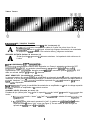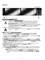
1
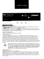
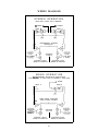
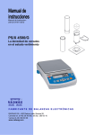
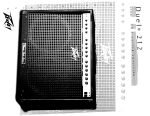
A
A
Intended to alert the user to the presence of uninsulated “dangerous voltage” within the product’s enclosure
that may be of sufficient magnitude to constitute a risk of electric shock to persons.
Intended to alert the user of the presence of important operating and maintenance (servicing) instructions in the
literature accompanying the product.
CAUTION: Risk of electrical shock - DO NOT OPEN!
CAUTION: To reduce the risk of electric shock, do not remove cover. No user serviceable parts inside. Refer servicing to
qualified service personnel.
WARNING: To prevent electrical shock or fire hazard, do not expose this appliance to rain or moisture. Before using this
appliance, read the operating guide for further warnings.
A
A
Este simbolo tiene el proposito de alertar al usuario de la presencia de “(voltaje) peligroso” que no tiene
aislamiento dentro de la caja de1 product0 que puede tener una magnitud suficiente coma para constituir riesgo de
corrientazo.
Este simbolo tiene el proposito de alertar al usario de la presencia de instruccones importantes sobre la operation
y mantenimiento en la literatura que viene con el producto.
PRECAUCION: Riesgo de corrientazo - No abra.
PRECAUCION: Para disminuir el riesgo de corrientazo, no abra la cubierta. No hay piezas adentro que el usario pueda
reparar. Deje todo mantenimiento a 10s tecnicos calificados.
ADVERTENCIA: Para evitar corrientazos o peligro de incendio, no deje expuesto a la lluvia o humedad este aparato
Antes de usar este aparato, lea m&s advertencias en la guia de operacibn.
A
A
Ce symbole est utilise pur indiquer a l’utilisateur la presence a l’interieur de ce produit de tension non-isolee
dangereuse pouvant &tre d’intensite suffisante pour constituer un risque de choc Clectrique.
Ce symbole est utilise pour indiquer a l’utilisateur qu’il ou qu’elle trouvera d’importantes instructions sur
l’utilisation et l’entretien (service) de l’appareil dans la litterature accompagnant le produit.
ATTENTION: Risques de choc Clectrique - NE PAS OUVRIR!
ATTENTION: Afin de reduire le risque de choc blectrique, ne pas enlever le couvercle. 11 ne se trouve a l’interieur
aucune piece pouvant &tre reparee par l’utilisateur. Confier l’entretien a un personnel qualifie.
AVERTISSEMENT: Afin de prtvenir les risques de decharge Clectrique ou de feu, n’exposez pas cet appareil a la pluie
ou a l’humidid. Avant d’utiliser cet appareil, lisez les avertissements supplementaires situ& dans le guide.
A
A
Dieses Symbol sol1 den Anwender vor unisolierten gefahrlichen Spannungen innerhalb des Gehauses warnen, die
von Ausreichender St%rke sind, urn einen elektrischen Schlag verursachen zu konnen.
Dieses Symbol sol1 den Benutzer auf wichtige Instruktionen in der Bedienungsanleitung aufmerksam machen, die
Handhabung und Wartung des Produkts betreffen.
VORSICHT: Risiko - Elektrischer Schlag! Nicht iiffnen!
VORSICHT: Urn das Risiko eines elektrischen Schlages zu vermeiden, nicht die Abdeckung enfernen. Es befinden sich
keine Teile darin, die vom Anwender repariert werden konnten. Reparaturen nur von qualifiziertem Fachpersonal
durchfiihren lassen.
ACHTUNG: Urn einen elektrischen Schlag oder Feuergefahr zu vermeiden, sollte dieses Gerat nicht dem Regen oder
Feuchtigkeit ausgesetzt werden. Vor Inbetriebnahme unbedingt die Bedienungsanleitung lesen.
2
FRONT PANEL FEATURES
DDTTM ACTIVE LED INDICATOR (1)
Illuminates when DDTTM compression is taking place. This LED becomes a clip indicator when the rear
panel DDTTM ENABLE/DEFEAT switch is in the DEFEAT position.
OPERATION NOTE: It is normal for the DDTTM LED(s) to flash occasionally during amplifier operation. If
the LED(s) remain on continuously, additional headroom is needed. In some cases, this may mean that the
particular application requires a more powerful amplifier.
POWER LED INDICATOR (2)
Illuminates when AC power is supplied to the amplifier.
CIRCUIT BREAKER (3)
This breaker is provided to limit the current to the associated power transformer and protect it from
overheating and possible destruction due to fault conditions in the amplifier. The trip current values have
been carefully chosen to allow continuous power output performance while still protecting the power
transformer. Normally, these breakers should not trip unless there is a fault in the amplifier circuitry that
draws excessive mains current. However, abnormal conditions such as a short circuit on either or both
channels, or continuous operation at overload or clipping (especially into 4 ohm load) will cause the breaker
to trip. If this occurs, turn the power switch off, then simply reset the breaker and correct the cause of the
overload.
When tripped, the button on the breaker will be outward nearly l/2” and can be reset by
pushing inward. A normal reset button length is about l/4”. If this “thermal” type breaker does
trip, simply pushing the button back in will reset it, after waiting a brief period of time to allow
it to cool down. REMEMBER, ALWAYS TURN THE POWER OFF BEFORE RESETTING
THE BREAKER. If the breaker trips instantly each time you attempt to reset it, the unit
should be taken to a qualified service center for repair.
A
POWER SWITCH (4)
Depress to the “I” position to turn the amplifier on.
OPERATION NOTE: This unit is equipped with automatic resetting thermal protection. If extremely high
operating temperatures cause the protection circuit to engage, the unit will shut down. Once it has cooled
sufficiently, the protection circuit will disengage and the amplifier will be re-enabled. Continued thermal
cycling indicates a load problem exists (shorted cable or the total speaker load is too low), or there is inadequate ventilation.
3
Back Panel:
0
6
BACK PANEL FEATURES
LINE CORD - 120 V products only (5)
A
For your safety, we have incorporated a three-wire line (mains) cable with proper grounding
facilities. It is not advisable to remove the ground pin under any circumstances. If it is
necessary to use the equipment without proper grounding facilities, suitable grounding
adaptors should be used. Less noise and greatly reduced shock hazard exists when the unit
is operated with properly grounded receptacles.
SPEAKER OUTPUTS (6)
A
Provided for connection of external speaker(s). Minimum total impedance is 4 ohms.
DDTTM COMPRESSION (7)
Each of the two internal power amplifiers is equipped with Peavey’s patented DDTTM Compression. The
DDT circuits will automatically engage to prevent clipping distortion within the power amplifiers. Compression is defeated when the pushbutton is “in”. DDTTM should be enabled at all times to protect speakers.
INPUT SENSITIVITY (8)
Maximum input gain (minimum sensitivity rating) is achieved at the full clockwise setting. A setting of less
than full clockwise will yield lower system noise at the expense of headroom. Calibration indicates sensitivity
in volts/dBV necessary to attain full available output.
OPERATION NOTE: The input sensitivity rating of a power amplifier is the voltage level required to drive the
amplifier to full output.
CHANNEL INPUTS (9)
Standard l/4” phone jacks with a special switching function to allow two modes of operation:
a. For normal STEREO operation, each jack is used as the input to the respective channel
(see fig. 1).
b. For dual-channel MONO operation, the A input jack may be used by inserting the plug only to the
first “click” or detent (see fig. 2). In this mode, the signal source is applied equally to both
channels.
4
SPECIFICATIONS
Frequency Response:
Output Power:
+0, -1 dB, 20 Hz to 30 kHz, 1 W RMS, 8 ohms
4 ohms, 1 kHz at 1% THD: 130 W RMS
8 ohms, 1 kHz at 1% THD: 100 W RMS
2 ohms not recommended
Damping Factor:
8 ohms, 1 kHz: Greater than 200
Rated Output Power:
Hum & Noise:
4 ohms, 20 Hz to 20 kHz, 0.1% THD: 100 W RMS
8 ohms, 20 Hz to 20 kHz, 0.1% THD: 90 W RMS
(below rated output power)
8 ohms, 100 dB, unweighted
Slew Rate:
Power Consumption:
Stereo mode, each channel: 20 volts/uSec
(63 rated output power)
Domestic: 600 watts, 60 Hz, 120 V AC
Export: 600 watts, 50/60 Hz, 230 V AC
Total Harmonic Distortion:
20 Hz to 20 kHz @ rated power, 8 ohms: Less
than 0.1%
Dimensions & Weight:
Height: 3.5”
W i d t h : 19”
Depth:
9.6”
Weight: 15.6 Ibs.
Input Sensitivity & Impedance:
(63 rated output power)
4 ohms: 1 .O V RMS, 0 dBV; 20 k ohms (26 dB)
A
Due to OUT efforts for constant improvements,
features and specifications listed herein are subject to change without notice.
5
WIRING DIAGRAMS
STEREO OPERATION
BOTH
INPUT
PLUGS
FULLY
Ei SIGNAL 4
INSERTED
W A SIGNAL
INPUT S
INPUT A
INDEPENDENT
CHANNEL
130W RMS
4 OHMS
q
A
SPEAKER JACKS
WIRED IN PARALLEL
SPEAKER JACKS
WIRED IN PARALLEL
MONO OPERATION
BOTH C H A N N E L S D R I V E N W I T H S I N G L E I N P U T
PLUG INSERTED TO FIRST CLICK IN CHANNEL A INPUT ONLY
A
INPUT A
B
I
SIGNAL
INPUT
q
SAME SIGNAL AVAILABLE
FROM EITHER CHANNEL
SPEAKER
OUTPUT
13DW R M S
4 OHMS
q
A
SPEAKER JACKS
WIRED IN PARALLEL
SPEAKER JACKS
WIRED IN PARALLEL
6
Consulte 10s diagramas de1 panel
delantero en la seccih de inglks de este manual.
FUNCIONES DE TABLERO FRONTAL
DDTTM ACTIVE LED (Indicador de actividad de DDTTM) (1)
Se ilumina cuando el compresion DDTTM esta funcionando. Con el interruptor “ENABLE/DEFEAT” (Habilitar/
Anular) en la position “DEFEAT” (Anular), el LED indica cuando occure recortes de picas de seriales
(distorsion).
Nota de Operation: Es normal que 10s LED del DDTTM se iluminen ocasionalmente durante la operation
del amplificador. Si permanecen iluminadas continuamente, es indication que se necesario mas “headroom”. En algunos cases, esto puede significar que es necesario tener un amplificador mas poderoso para
esa aplicacion determinada.
POWER LED INDICATOR (Indicador LED de encendido) (2)
Se ilumina cuando el amplificador recibe corriente alterna.
CIRCUIT BREAKER (Cortacircuito) (3)
Este cortacircuitos se proporciona para limitar la corriente al transformador de potencia asociado y para
protegerlo contra sobrecalentamiento y una posible destruction debida a condiciones de falla en el
amplificador. Los valores de disparo de la corriente se han elegidos cuidadosamente para permitir un
rendimiento de salida de potencia continua, y sun asi, proporcionar una protection adecuada al
transformador de potencia. Normalmente, estos cortacircuitos no deben dispararse a menos que exista una
condition de falla en 10s circuitos del amplificador que exija una corriente excesiva de la red. Sin embargo,
las condiciones anormales coma un cortocircuito en alguno de 10s canales o en ambos, o un funcionamiento
continua con sobrecarga o con recortes por sobrecarga (especialmente en la carga a 4 ohms), haran que el
cortacircuito se dispare. Si esto ocurre, apague el interruptor de encendido y entonces simplemente
restablezca el cortacircuito y corrija la causa de la sobrecarga.
A
Cuando este disparado, el baton se extendera casi 12.70 mm, y se puede restablecer
oprimiendolo hacia adentro. El largo normal del baton de restablecimiento es de alrededor
de 6.35 mm. Si este cortacircuito de tipo &rmico>> se dispara, con solo oprimir el baton se
restablecera despues de esperar un breve period0 de tiempo para permitir que se enfrie.
Recuerde: apague siempre el interruptor de encendido antes de restablecer el
cortacircuito. Si el cortacircuito se dispara instantaneamente cada vez que intente
restablecerlo, entonces debe llevar la unidad a un centro de servicio calificado para que sea
reparada.
POWER SWITCH (Interruptor de corriente) (4)
Empuje este interruptor a la position “I” para encender el aparato.
Nota de Operation: Esta unidad esta equipada con un protector termico de reencendido. Si temperaturas
extremadamente altas son alcanzadas, el circuit0 protector apagarala unidad. Una vez que el equip0 se ha
enfriado lo suficiente, el circuit0 protector se desactivara dejando operativo nuevamente el equipo. Cuando
esta ciclo de protection suceda a menudo es indication de un problema de sobrecarga (cable en corto
circuit0 o la carga de las altavoces es muy baja) o de inadecuada ventilation.
Tablero Trasero:
FUNCIONES DEL TABLERO TRASERO
REMOVABLE LINE CORD (Cable de corriente para 120 V solamente) (5)
A
A
Para su protection hemos incorporado un cable de 3 polos con polo a tierra. No es
recomendable remover la pata del polo a tierra bajo ninguna circunstancia, se recomienda
un adaptador en case necesario. Esto reducira ruidos y peligrosos corrientazos.
SPEAKER OUTPUTS (Salidas de altavoces) (6)
Se han provisto para conectar 10s altavoces exteriores. La impedancia total minima es de
4 ohms.
DDTTM COMPRESSION (DDTTM compresih) (7)
Cada uno de 10s amplificadores internos estas equipados con Peavey’s patentado el sistema de DDT
compresion. El circuit0 DDT se enciende automaticamente para prevenir distorsion dentro de 10s
amplificadores. DDT compresion se desactiva cuando el baton se encuentra oprimido (position IN). DDT
debe ser activado siempre para proteger las altavoces.
INPUT SENSITIVITY (Sensibilidad de entrada) (9)
La ganancia maxima de entrada (minim0 de sensibilidad) es alcanzado girando el control completamente a
la derecha. Si no se coloca el control completamente a la derecha producira conjuntos mas bajos dereido a
costa del “headroom”. La calbracion indica sensibilidad expresada en volts/dBV necesarios para obtener
toda la salida disponsible.
Nota de Operation: El grado de sensibilidad de entrada de un amplificador es el nivel de voltage requerido
para hater funcionar un amplificador a su potencia maxima.
CHANNEL INPUTS (Entradas de canal) (10)
Entradas de tipo “phone jacks” de l/4” con un especial funcion de “switch” para permitir la operation en dos
modos.
a. Para operation normal a “stereo” cada “jack” es usado coma la entrada del canal respective (ver
figura 1).
b. Para operation de doble-canal monoaural la “jack” A pueden ser usados inertando el macho
solamente hasta el primer “click” o tope (ver figura 2). En este modo, la serial d origen es
aplicada de manera igual a 10s dos canales.
8
Veuillez vous rbfbrer au “front panel art”
situ6 dans la section en langue anglaise de ce manuel.
CARACTERISTIQUES DU PANNEAU AVANT
DDTTM ACTIVE LED (DEL tkmoin de DDTTM) (1)
S’allume lorsque le circuit de compression DDT intervient. Si I’interrupteur “Enable/Defeat” est en position
“Defeat”, la DEL temoin indique lorsqu’il y a de la distorsion causee par ecretement.
Remarque : II est normal que la ou les DELs temoins de DDT clignotent occasionnellement durant le
fonctionnement de I’amplificateur. Si la ou les DELs temoins resent continuellement allumees, ceci indique
un manque de reserve de puissance (“headroom”). Dans certains cas, cela peut signifier que cette application necessite un amplificateur plus puissant.
POWER LED INDICATOR (Indicateur DEL d’alimintation) (2)
S’allume lorsque I’ampli recoit I’alimentation CA.
CIRCUIT BREAKER (Disjoncteur) (3)
Ce disjoncteur limite le courant recu par le transformateur et protege ainsi celui-ci d’une surchauffe et d’une
destruction eventuelle a la suite dune defaillance de I’amplificateur. La valeur de declenchement de ce
disjoncteur a ete soigneusement etudiee de maniere a permettre une alimentation de sortie continuelle tout
en protegeant le transformateur. Normalement, ce type de disjoncteur ne se declenche que s’il existe une
defaillance des circuits de I’amplificateur faisant passer un courant secteur excessif. Toutefois, des
conditions anormales, telles qu’un court-circuit d’un ou des deux canaux ou un fonctionnement continue1
avec surcharge ou ecretage (particulierement en charge de 4 ohms) peuvent declencher le disjoncteur.
Dans ce cas, il convient de mettre I’appareil hors tension, de remettre le disjoncteur dans sa position initiale
et d’eliminer la cause du declenchement.
Lorsque le disjoncteur se declenche, son bouton est sorti d’environ 12,7 mm (l/2 PO.) et il
suffit de I’enfoncer pour le remettre en place. Normalement, ce bouton depasse d’environ
6,35 mm (l/4 PO.). Si ce type de disjoncteur << thermique >’ se declenche, il suffit d’enfoncer
son bouton pour le remettre dans sa position initiale apres avoir attendu un instant qu’il
refroidisse. N’oubliez pas de toujours mettre I’appareil hors tension avant de remettre
le disjoncteur dans sa position initiale. Si le disjoncteur se declenche a chaque tentative
de remise a l’etat initial, I’appareil doit etre porte a un technicien qualifie pour reparation.
A
POWER SWITCH (Interrupteur d’alimentation) (4)
Appuyez jusqu’en position “I” pour mettre sous tension.
Remarque : Cet appareil est equipe dune protection thermique a rearmement automatique. Au cas ou la
temperature de fonctionnement depasserait la limite autorisee, la protection arretera I’appareil. Apres
refroidissement, I’appareil se remettra en route de lui-meme. Des arrets repetes temoignent d’un probleme a
9
Panneau Arriere :
la sortie (cable en court-circuit ou impedance de charge totale trop faible) ou dune ventilation insuffisante.
CARACTBRISTIQUES DU PANNEAU ARRIBRE
REMOVABLE LINE CORD (Cordon d’alimentation pour appareils 120V seulement) (5)
A
Pour votre securite, nous avons incorpore un cable d’alimentation secteur a 3 fils avec misea-terre appropriee. II nest pas recommande d’enlever la broche de mise-a-terre en aucune
circonstance. S’il est necessaire d’utiliser I’equipement sans mise-a-terre appropriee, utilisez
des adapteurs de mise-a-terre convenables. Une bonne mise-a-terre amoindrit le bruit de
fond et reduit grandement les risques de choc.
SPEAKER OUTPUTS (Sorties de haut-parleurs) (6)
A
Ces prises permettent le branchement de haut-parleurs externes. L’impedance totale
minimale est de 4 Ohms.
DDTTM COMPRESSION (Compression de DDTTM) (7)
Chacun des deux amplificateurs de puissance incorpores est equipe d’un circuit de compression PEAVEY’S
brevete DDTTM. Ce circuit se met automatiquement en service en cas de besoin pour eviter une distorsion
par ecretage dans les amplis de puissance.
La compression DDT est mise en circuit lorsque le bouton est enfonce. Pour proteger les haut-parleurs,
nous recommandons de la laisser en service.
INPUT SENSITIVITY (Sensibilitk d’entrbe) (8)
Le gain augmente en tournant le bouton dans le sens des aiguilles dune montre. Les positions inferieures
au maximum diminueront le niveau de bruit de fond, au detriment de la reserve de puissance. L’echelle
indique la sensibilite et le niveau en volts necessaire pour attendre la puissance de sortie maximum.
Remarque : La sensibilite d’entree d’un amplificateur de puissance est la tension necessaire pour atteindre
la puissance maximum.
CHANNEL INPUTS (Prises d’entrhe) (9)
Prise jack 6,35 permettant 2 modes d’utilisation:
a. Stereo normale : chacune des deux prises donne acces au canal considere (gauche et droit)
(voir figure 1).
b. Double mono : en n’utilisant qu’une seule des deux prises par insertion dune fiche jack au
premier cran (voir figure 2). Le signal sera alors egalement applique aux deux cannaux.
10
Siehe Diagramm der Frontplatte im englischen Teil des Handbuchs.
BESCHREIBUNG DER FRONTPLATTE
DDTTM ACTIVE LED (DDTTM aktiv LED) (1)
Leuchtet auf, sobald die DDT-Schaltung durch entsprechende Pegel aktiviert wird. Bei ausgeschalteter DDTKompression (Enable/Defeat-Taste nicht eingedruckt) zeigt ein Aufleuchten an, daf3 zu diesem Zeitpunkt
Verzerrungen (Clipping) entstehen.
ANWENDUNGS-HINWEIS: Ein zeitweiliges Aufleuchten der DDT-LED(s) ist normal. Ein standiges
Aufleuchten der LED(s) hingegen bedeutet, daB die Ubersteuerungsreserve der Endstufe erschopft ist, und
daB fur diese Anwendung eine starkere Endstufe eingesetzt werdon sollte.
POWER LED INDICATOR (Power LED Anzeig) (2)
Leuchtet auf, wenn das Gerat eingeschaltet ist.
CIRCUIT BREAKER (Unterbrecher) (3)
Dieser Unterbrecher dient zum Begrenzen des Stroms, der zum zugehorigen Netztransformator flieBt, und
urn ihn gegen Uberhitzung und mogliche Schaden aufgrund von Fehlerzustanden im Verstarker zu
schutzen. Die Auslosestromwerte wurden sorgfaltig gewahlt, so daB eine kontinuierliche hohe
Ausgangsleistung moglich ist und trotzdem ein ausreichender Schutz fur den Netztransformator
gewahrleistet ist. Normalerweise werden diese Unterbrecher nur ausgelost, wenn in der
Verstarkungsschaltung ein Fehler vorliegt, der eine ubermaBige Leistungsaufnahme verursacht. Nicht
normale Zustande wie beispielsweise ein KurzschluB in einem oder beiden Kanalen oder Dauerbetrieb bei
Uberlastung oder Ubersteuerung (vor allem an 4 Ohm) bewirken jedoch die Auslosung des Unterbrechers.
Sollte dies vorkommen, schalten Sie den Netzschalter aus, korrigieren Sie die Ursache der Uberlastung und
stellen Sie einfach den Unterbrecher zuruck.
Im ausgeldsten Zustand ragt der Knopf des Unterbrechers tiber 1 cm hervor, zum
Zurtickstellen wird er einfach wieder zuruckgedruckt. Im zuriickgestellten Zustand ragt der
Knopf etwa 5 mm hervor. Wenn dieser Thermalunterbrecher ausgelost wird, wird er einfach
durch Zurtickdrucken des Knopfs zurtickgestellt, nachdem eine kurze Zeitdauer gewartet
wurde, damit das Gerat abkuhlen kann. Denken Sie daran, immer die
Spannungsversorgung auszuschalten, bevor Sie den Unterbrecher zuriickstellen.
Sollte der Unterbrecher bei jedem Zurtickstellen sofort wieder ausgelost werden, sollte das
Gerat von einem qualifizierten Reparaturdienst ijberpruft werden.
A
POWER SWITCH (Netzschalter) (4)
Zum Einschalten in Position “I” drucken.
ANWENDUNGS-HINWEIS: Dieses Gerat ist mit einem Uberhitzungsschutz. Beim Auftreten extrem hoher
Betriebstemperaturen wird der Schutz aktiviert und das Gerat ausgeschaltet. Nach ausreichender
Abkijhlung wird der Schutz aufgehoben und das Gerat wieder eingeschaltet. Eine standig wiederkehrende
Aktivierung des Schutzes deutet auf ein Ausgangs-Problem (Kabel-Kurzschluss, Gesamt-lmpedanz des/der
angeschlossenen Lautsprecher zu niedrig), oder auf ungenugende Ventilation (Hitzestau).
11
Riickplatte:
0
6
BESCHREIBUNG DER RiiCKPLATTE
REMOVABLE LINE CORD (Nur bei 120 Volt-Geraten) (5)
A
Zu ihrer Sicherheit haben wir das Gerat mit einem dreiadrigen geerdeten Netzkabel
versehen. Es ist unter keinen Umstanden empfehlenswert den Erdungskontakt des
AnschluBkabels zu l&en. Falls es notwendig sein sollte, das Equipment ohne die
vorgesehene Erdung zu betreiben empfiehlt sich die Verwendung eines Grounding Adaptors.
Die geringsten Stbrgerausche und die hdchste Sicherheit vor elektrischen Schlagen wird
jedoch durch die Benutzung der vorgesehenen Erdungsmoglichkeiten erreicht.
SPEAKER OUTPUTS (Lautsprecherbuchsen) (6)
A
An diese Buchsen kdnnen externe Lautsprecher. Die minimale Gesamtimpedanz betragt
4 Ohms.
DDTTM COMPRESSION (DDTTM-Kompression) (7)
Jeder der zwei internen Endstufen ist mit Peavey’s DDTT”-Kompression ausgestattet. Die DDTKompression wird automatisch aktiviert urn Verzerrungen durch zu hohe Pegel Vorzubeugen.
Die DDT-Kompression ist bei eingedruckter Taste ausgeschaltet (“Defeat”). Die DDT-Kompression sollte
zum Schutz der Lautsprecher standig eingeschaltet (“Enable”) bleiben.
INPUT SENSITIVITY (Eingangs-Empfindlichkeit) (8)
Die maximale Eingangs-Verstarkung (niederste Empfindlichkeit) wird bei voll im Uhrzeigersinn geoffneten
Regler erreicht. Bei weniger geoffnetem Regler wird eine Verminderung des Rauschens erreicht, allerdings
auf Kosten der Ubersteuerungsfestigkeit. Die auf gedruckte Kalibrierung zeigt die benotigte Empfindlichkeit
in Volt/dBV an, urn die voile Ausgangsleistung zu erreichen.
ANWENDUNGS-HINWEIS: Die Eingangs-Empfindlichkeit der Endstufe stellt die Spannung in Volt dar,
welche benotigt wird, urn die voile Ausgangsleistung des Verstarkers zu erreichen.
CHANNEL INPUTS (Kanal-Eingsnge) (9)
l/4”-Zoll-Klinkenstecher-Anschliisse mit speziellen Schaltfunktionen fur zwei verschiedene Betriebsarten.
a. Bei normalem “Stereo”-Betrieb werden ein Anschluss pro Kanal verwendet (siehe Abbildung 1)
b. Bei zwei-kanaligem “Mono”-Betrieb wird wahlweise der A-Anschluss verwendet, und der
Klinkenstecher nur bis zum ersten “klicken” (erste Vertiefung am Stecker) eingesteckt (siehe
Abbildung 2). In dieser Betriebsart wird das Eingangssignal gleichmassig auf beide Kanale
verteilt.
12
For further information on other Peavey products,
ask your Authorized Peavey Dealer for the
appropriate Peavey catalog/publication.
Bass Guitars
Guitars
Bass Amplification
Guitar Amplification
Sound Reinforcement Enclosures
Microphones
Keyboards
DJ
Lighting
Mixers, Powered/Non-Powered
Accessories/Cables
Effects Processors
Axcess’” Wear
The Peavey Beat’”
Monitor@ Magazine
Key Issues’”
Low Down’”
PM’” Magazine
13
THIS LIMITED WARRANTY VALID ONLY WHEN PURCHASED AND REGISTERED IN THE UNITED STATES OR CANADA. ALL EXPORTED PRODUCTS
ARE SUBJECT TO WARRANTY AND SERVICES TO BE SPECIFIED AND PROVIDED BY THE AUTHORIZED DISTRIBUTOR FOR EACH COUNTRY.
Ces clauses de garantie ne sont vaiables qu’aux Eta&-Unis et au Canada. Dans tour les autres pays, les clauses de garantie et de maintenance sont
fixees par le distributeur national et assuree par lul seion la legislation envigueur. l l Diese Garantie ist nur in den USA and Kanada gultig. Alle ExportProdukte sind der Garantie und dem Service des lmporteurs des jewelligen Landes unterworfen. l l Esta garantia es valida solamente cuando el
product0 es comprado en E.U. continentales o en Canada. Todos 10s productos que Sean comprados en el extranjero, estan sujetos a las garantias y
servicio que cada distribuidor autorizado determine y ofrezca en 10s diferentes paises.
PEAVEY ONE-YEAR LIMITED
WARRANTY/REMEDY
PEAVEY ELECTRONICS CORPORATION (“PEAVEY”) warrants this product, EXCEPT for covers, footswitches, patchcords, tubes and meters, to be free from
defects in material and workmanship for a period of one (1) year from date of purchase, PROVIDED, however, that this limited warranty is extended only to the
original retail purchaser and is subject to the conditions, exclusions, and limitations heremafter set forth:
PEAVEY BO-DAY LIMITED WARRANTY ON TUBES AND METERS
If this product contains tubes or meters, Peavey warrants the tubes or meters contatned in the product to be free from defects in material and workmanship for
a period of ninety (90) days from date of purchase; PROVIDED, however, that this limited warranty is extended only to the original retail purchaser and is also
subject to the conditions, exclusions, and limitations hereinafter set forth.
CONDITIONS, EXCLUSIONS, AND LIMITATIONS OF LIMITED WARRANTIES
These limited warranties shall be void and of no effect, if:
a. The first purchase of the product is for the purpose of resale; or
b. The original retail purchase IS not made from an AUTHORIZED PEAVEY DEALER; or
c. The product has been damaged by accident or unreasonable use, neglect, improper service or mamtenance, or other causes not arising out of defects in
material or workmanship; or
d. The serial number affixed to the product is altered, defaced, or removed.
In the event of a defect in material and/or workmanship covered by this limited warranty, Peavey will:
a. In the case of tubes or meters, replace the defective component without charge.
b. In other covered cases (i.e., cases involving anything other than covers, footswitches, patchcords, tubes or meters), repair the defect I” material or
workmanship or replace the product, at Peavey’s option; and provided, however, that, in any case, all costs of shipplng, If necessary, are paid by you, the
purchaser.
THE WARRANTY REGISTRATION CARD SHOULD BE ACCURATELY COMPLETED AND MAILED TO AND RECEIVED BY PEAVEY WITHIN FOURTEEN (14)
DAYS FROM THE DATE OF YOUR PURCHASE.
In order to obtain service under these warranties, you must:
a. Bring the defective item to any PEAVEY AUTHORIZED DEALER or AUTHORIZED PEAVEY SERVICE CENTER and present therewith the ORIGINAL
PROOF OF PURCHASE supplied to you by the AUTHORIZED PEAVEY DEALER in connection with your purchase from him of this product.
If the DEALER or SERVICE CENTER is unable to provide the necessary warranty service you will be directed to the nearest other PEAVEY AUTHORIZED
DEALER or AUTHORIZED PEAVEY SERVICE CENTER which can provide such service.
OR
b. Ship the defective item, prepaid, to:
PEAVEY ELECTRONICS CORPORATION
International Service Center
326 Hwy. 11 & 80 East
Meridian, MS 39301
including therewith a complete, detailed description of the problem, together with a legible copy of the original PROOF OF PURCHASE and a complete return
address. Upon Peavey’s receipt of these items: If the defect is remedial under these limited warranties and the other terms and conditions expressed herein
have been complied with, Peavey will provide the necessary warranty service to repair or replace the product and will return it, FREIGHT COLLECT, to you,
the purchaser.
Peavey’s liability to the purchaser for damages from any cause whatsoever and regardless of the form of action, including negligence, is limited to the actual
damages up to the greater of $500.00 or an amount equal to the purchase price of the product that caused the damage or that is the subject of or is directly related
to the cause of action. Such purchase price will be that in effect for the specific product when the cause of action arose. This limitation of liability WIII not apply to
claims for personal injury or damage to real property or tangible personal property allegedly caused by Peavey’s negligence. Peavey does not assume liability for
personal injury or property damage arising out of or caused by a non-Peavey alteration or attachment, nor does Peavey assume any responsibility for damage to
interconnected non-Peavey equipment that may result from the normal functioning and maintenance of the Peavey equipment.
UNDER NO CIRCUMSTANCES WILL PEAVEY BE LIABLE FOR ANY LOST PROFITS, LOST SAVINGS, ANY INCIDENTAL DAMAGES, OR ANY
CONSEQUENTIAL DAMAGES ARISING OUT OF THE USE OR INABILITY TO USE THE PRODUCT, EVEN IF PEAVEY HAS BEEN ADVISED OF THE
POSSIBILITY OF SUCH DAMAGES
THESE LIMITED WARRANTIES ARE IN LIEU OF ANY AND ALL WARRANTIES. EXPRESSED OR IMPLIED, INCLUDING, BUT NOT LIMITED TO, THE
IMPLIED WARRANTIES OF MERCHANTABILITY AND FITNESS FOR A PARTICULAR USE; PROVIDED, HOWEVER, THAT IF THE OTHER TERMS AND
CONDITIONS NECESSARY TO THE EXISTENCE OF THE EXPRESSED, LIMITED WARRANTIES, AS HEREINABOVE STATED, HAVE BEEN COMPLIED
WITH, IMPLIED WARRANTIES ARE NOT DISCLAIMED DURING THE APPLICABLE ONE-YEAR OR NINETY-DAY PERIOD FROM DATE OF PURCHASE OF
THIS PRODUCT.
SOME STATES DO NOT ALLOW LIMITATION ON HOW LONG AN IMPLIED WARRANTY LASTS, OR THE EXCLUSION OR LIMITATION OF INCIDENTAL
OR CONSEQUENTIAL DAMAGES, SO THE ABOVE LIMITATIONS OR EXCLUSIONS MAY NOT APPLY TO YOU. THESE LIMITED WARRANTIES GIVE YOU
SPECIFIC LEGAL RIGHTS, AND YOU MAY ALSO HAVE OTHER RIGHTS WHICH MAY VARY FROM STATE TO STATE.
THESE LIMITED WARRANTIES ARE THE ONLY EXPRESSED WARRANTIES ON THIS PRODUCT, AND NO OTHER STATEMENT, REPRESENTATION,
WARRANTY, OR AGREEMENT BY ANY PERSON SHALL BE VALID OR BINDING UPON PEAVEY.
In the event of any modification or disclaimer of expressed or implied warranties, or any limitation of remedies, contatned herein conflicts with applicable law,
then such modification, disclaimer or limitation, as the case may be, shall be deemed to be modified to the extent necessary to comply with such law.
Your remedies for breach of these warranties are limited to those remedies provided herein and Peavey Electronics Corporation gives this limited warranty only
with respect to equipment purchased in the United States of America.
INSTRUCTIONS -WARRANTY REGISTRATION CARD
1. Mail the completed WARRANTY REGISTRATION CARD to:
PEAVEY ELECTRONICS CORPORATION
P.O. BOX 2898
Meridian, MS 39302-2898
a. Keep the PROOF OF PURCHASE. In the event warranty service is required during the warranty period, you will need this document. There will be no
identification card issued by Peavey Electronics Corporation.
2. IMPORTANCE OF WARRANTY REGISTRATION CARDS AND NOTIFICATION OF CHANGES OF ADDRESSES:
a. Completion and mailing of WARRANTY REGISTRATION CARDS - Should notification become necessary for any condition that may require correction,
the REGISTRATION CARD will help ensure that you are contacted and properly notified.
b. Notice of address changes - If you move from the address shown on the WARRANTY REGISTRATION CARD, you should notify Peavey of the change of
address so as to facilitate your receipt of any bulletins or other forms of notification which may become necessary in connectlon with any condition that may
require dissemination of information or correction.
3. You may contact Peavey directly by telephoning (601) 483-5365.
14
IMPORTANT SAFETY INSTRUCTIONS
WARNING: When using electric products, basic cautions should always be followed, including the following.
1.
Read all safety and operating instructions before using this product.
2.
All safety and operating instructions should be retained for future reference.
3.
Obey all cautions in the operating instructions and on the back of the unit.
4.
All operating instructions should be followed.
5.
This product should not be used near water, i.e., a bathtub, sink, swimming pool, wet basement, etc.
6.
This product should be located so that its position does not interfere with its proper ventilation. It should not be placed flat against a
wall or placed in a built-in enclosure that will impede the flow of cooling air.
7.
This product should not be placed near a source of heat such as a stove, radiator, or another heat producing amplifier.
8.
Connect only to a power supply of the type marked on the unit adjacent to the power supply cord.
9.
Never break off the ground pin on the power supply cord. For more information on grounding, write for our free booklet “Shock
Hazard and Grounding.”
10.
Power supply cords should always be handled carefully. Never walk or place equipment on power supply cords. Periodically check
cords for cuts or signs of stress, especially at the plug and the point where the cord exits the unit.
11.
The power supply cord should be unplugged when the unit is to be unused for long periods of time.
12.
If this product is to be mounted in an equipment rack, rear support should be provided.
13.
Metal parts can be cleaned with a damp rag. The vinyl covering used on some units can be cleaned with a damp rag or an ammoniabased household cleaner if necessary. Disconnect unit from power supply before cleaning.
14.
Care should be taken so that objects do not fall and liquids are not spilled into the unit through the ventilation holes or any other
openings.
This unit should be checked by a qualified service technician if:
a. The power supply cord or plug has been damaged.
b. Anything has fallen or been spilled into the unit.
c. The unit does not operate correctly.
d. The unit has been dropped or the enclosure damaged.
15.
16.
The user should not attempt to service this equipment. All service work should be done by a qualified service technician.
17.
This product should be used only with a cart or stand that is recommended by Peavey Electronics.
18.
Exposure to extremely high noise levels may cause a permanent hearing loss. Individuals vary considerably in susceptibility to noise
induced hearing loss, but nearly everyone will lose some hearing if exposed to sufficiently intense noise for a sufficient time.
The U.S. Government’s Occupational Safety and Health Administration (OSHA) has specified the following permissible noise level
exposures.
Sound Level dBA, Slow Response
90
92
95
97
100
102
105
110
115
Duration Per Day In Hours
8
6
4
3
2
1 l/2
I
l/2
I /4 or less
According to OSHA, any exposure in excess of the above permissible limits could result in some hearing loss.
Ear plugs or protectors in the ear canals or over the ears must be worn when operating this amplification system in order to prevent a
permanent hearing loss if exposure is in excess of the limits as set forth above. To ensure against potentially dangerous exposure to high
sound pressure levels, it is recommended that all persons exposed to equipment capable of producing high sound pressure levels such as
this amplification system be protected by hearing protectors while this unit is in operation.
SAVE THESE INSTRUCTIONS!
15
0
@ EquiAUdipmentrJ
UL
WXED
01995
Commercial
25E9
Features and specifications subject to change without notice.
Peavey Electronics Corporation 711 A Street / Meridian, MS 39301 I U.S.A. I (601) 483-5365 / Fax 486-1278
Printed in U.S.A. 1 l/95
#80304240