1
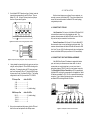
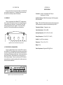
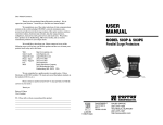
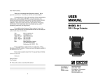
USER
MANUAL
MODEL 457B
Seven Port Active
Twinax Star Hub
Part #07M457B-C
Doc. #069011UC
Revised 4/22/98
An ISO-9001
Certified Company
SALES OFFICE
(301) 975-1000
TECHNICAL SUPPORT
(301) 975-1007
http://www.patton.com
1.0 WARRANTY INFORMATION
1.3 SERVICE
Patton Electronics warrants all Model 457B components to be
free from defects, and will—at our option—repair or replace the product
should it fail within one year from the first date of shipment.
This warranty is limited to defects in workmanship or materials, and
does not cover customer damage, abuse, or unauthorized modification.
If this product fails or does not perform as warranted, your sole
recourse shall be repair or replacement as described above. Under no
condition shall Patton Electronics be liable for any damages incurred
by the use of this product. These damages include, but are not limited
to, the following: lost profits, lost savings, and incidental or
consequential damages arising from the use of or inability to use this
product. Patton Electronics specifically disclaims all other warranties,
expressed or implied, and the installation or use of this product shall be
deemed an acceptance of these terms by the user.
1.1 RADIO AND TV INTERFERENCE
The Model 457B generates and uses radio frequency energy, and
if not installed and used properly—that is, in strict accordance with the
manufacturer's instructions—may cause interference to radio and
television reception. The Model 457B is designed to provide
reasonable protection from such interference in a commercial
installation. However, there is no guarantee that interference will not
occur in a particular installation. If the Model 457B does cause
interference to radio or television reception, which can be determined
by disconnecting the RS-232 interface, the user is encouraged to try to
correct the interference by one or more of the following measures:
moving the computing equipment away from the receiver, re-orienting
the receiving antenna, and/or plugging the receiving equipment into a
different AC outlet (such that the computing equipment and receiver are
on different branches).
All warranty and nonwarranty repairs must be returned freight
prepaid and insured to Patton Electronics. All returns must have a
Return Materials Authorization number on the outside of the shipping
container. This number may be obtained from Patton Electronics
Technical Service at
telephone: (301) 975-1007,
web address: http://www.patton.com;
email: [email protected].
NOTE: Packages received without an RMA number will not be
accepted.
Patton Electronics’ technical staff is also available to answer any
questions that might arise concerning the installation or use of your
Model 457B. Technical Service hours: 8AM to 5PM EST, Monday
through Friday.
1.2 CE NOTICE
The CE symbol on your Patton Electronics equipment indicates
that it is in compliance with the Electromagnetic Compatibility (EMC)
directive and the Low Voltage Directive (LVD) of the Union European
(EU). A Certificate of Compliance is available by contacting Patton
Technical Support.
1
2
2.0 GENERAL INFORMATION
Thank you for your purchase of this Patton Electronics product.
This product has been thoroughly inspected and tested and is
warranted for One Year parts and labor. If any questions or problems
arise during installation or use of this product, please do not hesitate to
contact Patton Electronics Technical Support at (301) 975-1007.
2.1 FEATURES
• Provides "Star" distribution for seven AS/400 or 3X terminals
• Supports cost-effective unshielded twisted pair communication
• Active signal regeneration enables hub-to-terminal distances of
2250 ft and host-to-terminal distances of 4500 ft
3.0 CONFIGURATION
The Model 457B offers the option of configuring individual RJ-45
ports for specific twisted pair pin-outs. This section tells how to access
and set the internally mounted jumpers for each port.
3.1 DEFAULT SIGNAL-TO-PIN CONFIGURATION
The Model 457B is configured at the factory so that RJ-45 pin 4
corresponds to TIP and RJ-45 pin 5 corresponds to RING. This
default setting applies to the single host connection as well as the
seven terminal connections. Figure 1 (below) shows the pin numbering
scheme Patton follows with respect to the RJ-45 jack. If your wiring
scheme uses RJ-45 pins 4 and 5 in the manner described above, you
may move on to Section 4.0 Installation.
• LED status indicators for each RJ-45 twisted pair port
• Transparent to data protocol—supports data rates to 1 Mbps
RING
TIP
• 100% compatible with Patton Model 410 Twinax baluns
• Separate signal-to-pin configuration for each port
1 2 3 4 5 6 7 8
• Transformer isolation at every port
RJ-45 Jack
Front View
2.2 DESCRIPTION
The Patton Model 457B AllStarTM is an active seven port
distribution hub for AS/400 and 3X systems. The Model 457B
distributes one twisted pair 1Mbps host to seven twisted pair 1Mbps
terminals. It is designed to be used in conjunction with Patton's Model
410 Series twinax baluns which adapt the host and terminal ports from
twinax to twisted pair.
The Model 457B features modular RJ-45 ports on the seven
terminal channels, and an RJ-45 port plus screw terminals on the host
channel. The host and terminal can be at distances up to 2250 feet,
and each terminal and its port can also be at distances up to 2250 feet.
This yields a maximum host-to-terminal distance of 4500 ft, and a total
aggregate cabling distance of 18,000 feet. The Model 457B has one
LED per port to indicate data activity. For added convenience, each
port has its own pair of internal straps that allow "tip" and "ring" to be
assigned to any of the eight RJ-45 pins.
Optional 19" rack mount hardware allows two Model 457Bs to be
installed side-by-side in a single 1U rack space. Additional space is
conserved by operating the two rack mounted 457Bs from a single AC
power supply harness. Power supplies of 120 or 240 volts are
available for both stand alone and rack mount units.
3
Figure 1. RJ-45 pin numbering scheme
showing default configuration
3.2 CHANGING THE SIGNAL-TO-PIN CONFIGURATION
If your RJ-45 twisted pair wiring scheme calls for pin-outs other
than TIP-4 and RING-5, you will need to re-configure the Model 457B
according to the following instructions.
1.
Make sure the Model 457B's power is OFF.
2.
Remove the two black Phillips head screws from the front of
the Model 457B and slide the PC board out of the case.
(continued)
4
4.0 INSTALLATION
3.
On the Model 457B PC board (see figure 2, below), locate the
jumper blocks corresponding to each RJ-45 port. They are
labeled JP1 - JP8. As figure 3 (below) shows, each jumper
block has 16 pins and two jumpers.
After the internal jumpers are configured for your equipment, you
are ready to connect up the Model 457B. This section explains how to
connect the host and terminals to the Model 457B in a star topology
using twisted pair cable.
4.1 CONNECTION TO THE HUB
Host Connection—The host port of the Model 457B allows RJ-45
or terminal block connection of a single twisted pair cable. The
maximum distance between the Model 457B and the host is 2250 feet.
Only one host may be connected to the hub at a time.
Figure 2. Model 457B PC board, showing jumper block locations
Terminal Connections—RJ-45 ports 00 - 06 on the Model 457B
allow connection of up to seven terminals using single pair cable. The
maximum distance between the Model 457B and each terminal is 2250
feet. Note: Pin-outs of RJ-45 cables must match the pin configurations
chosen for the Model 457B's ports (see Section 3.0 for more details).
Jumpers
4.2 CONNECTION TO HOST AND TERMINAL HARDWARE
Figure 3. Jumper block, showing two jumpers and pin correspondence to RJ-45
4.
Having located the jumper blocks for the ports you need to reconfigure, set the jumpers for TIP and RING according to the
table below. For example, placing the TIP jumper on jumper
pins 5 and 6 activates RJ-45 pin 3. Placing the RING jumper
on jumper pins 11 and 12 activates RJ-45 pin 6. The resulting
configuration for that RJ-45 port would be TIP-3, RING-6.
TIP Jumper Pins
Active RJ-45 Pin
1 & 2 ...................................1
3 & 4 ...................................2
5 & 6 ...................................3
7 & 8 ...................................4 (default setting)
Most AS/400 and System 3X hardware is equipped with twinax
ports, and is set up to communicate over twinax cable. In order to
communicate over a single twisted pair, you must use a twinax to
twisted pair adapter or "BALUN" at each host and terminal connection.
The Patton Model 410 Series Twinax Balun is 100% compatible with
the Model 457B, and is highly recommended for this application. Model
410 baluns are available for RJ-11, RJ-45, or terminal block twisted pair
connection. Figure 4 (below) illustrates wiring for a star network using
one Model 457B hub and eight Model 410 baluns.
RING Jumper Pins
Active RJ-45 Pin
9 & 10 .................................5 (default setting)
11 & 12................................6
13 & 14 ...............................7
15 & 16 ...............................8
5.
After you have repositioned the jumpers, slide the PC board
back into the case and replace the two Phillips screws.
5
Figure 4. A twisted pair star network for seven terminals
6
5.0 OPERATION
Having connected the host and terminal cables to the Model 457B,
you are ready to operate the unit. This section tells how to power the
unit, and how to read the port status LED indicators.
APPENDIX A
SPECIFICATIONS
Connectors: Host port—terminal block and RJ-45 jack
Terminal ports—RJ-45 jack
Applicable Hardware: IBM AS/400 and System 34/36/38 compatible
hosts and terminals
5.1 POWER UP
There is no power switch on the Model 457B. To apply power to
the unit, plug the AC adapter into one of the two rear jacks (see figure
5, below) and then into a wall outlet. The front panel "Power" LED
should glow yellow when power is applied. The port status LEDs
should be off if the host and terminals are not yet powered up.
Range: 2250 ft (24 AWG unshielded twisted pair) between the hub and
each connected device; maximum host-to-terminal range is 4500 ft
Transmission Protocol: Transparent to user
Link-to-Data Isolation: 500 Volts RMS
Power Jacks
Operating Temperature: 40°F to 130°F (5°C to 54°C)
Storage Temperature: 0°F to 185°F (-17°C to 85°C)
Humidity: Up to 95% non-condensing
Figure 5. Rear panel of Model 457B, showing power jacks
Dimensions: 7.25"w x 1.6"h x 3.75"d
Weight: 0.9 lb
5.2 "PORT STATUS" LED INDICATORS
Power Requirements: Regulated 5VDC @ 250 mA
As figure 6 (below) illustrates, there is a status LED for each port
on the Model 457B. Having followed the normal start-up procedures for
your system, the host port LED should glow faintly red and each active
terminal port's LED should glow faintly green. Inactive ports should not
show any LED activity. When data activity is occurring on a port, its
LED should glow brightly. Failure of a particular port's LED to behave
as described here may indicate a problem with the cable connection or
with the host/terminal hardware.
Figure 6. Front panel of Model 457B, showing LED indicators
7
8