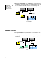
1
Automation
Ethernet Networking
for 6K and Gem6K
Effective: February 11, 2002
User Information
WARNING
!
!
6K and Gem6K Series products are used to control electrical and
mechanical components of motion control systems. You should test your
motion system for safety under all potential conditions. Failure to do so
can result in damage to equipment and/or serious injury to personnel.
6K and Gem6K Series products and the information in this user guide are the proprietary property of Parker Hannifin Corporation or its
licensers, and may not be copied, disclosed, or used for any purpose not expressly authorized by the owner thereof.
Since Parker Hannifin constantly strives to improve all of its products, we reserve the right to change this user guide and software and
hardware mentioned therein at any time without notice.
In no event will the provider of the equipment be liable for any incidental, consequential, or special damages of any kind or nature
whatsoever, including but not limited to lost profits arising from or in any way connected with the use of the equipment or this user guide.
© 2002, Parker Hannifin Corporation
All Rights Reserved
Motion Planner and Servo Tuner are trademarks of Parker Hannifin Corporation.
Microsoft and MS-DOS are registered trademarks, and Windows, Visual Basic, and Visual C++ are trademarks of Microsoft Corporation.
Technical Assistance
Contact your local automation technology center (ATC) or distributor, or ...
North America and Asia:
Europe (non-German speaking):
Germany, A ustria, Switzerland:
Compumotor Division of Parker Hannifin
5500 Business Park Drive
Rohnert Park, CA 94928
Telephone: (800) 358-9070 or (707) 584-7558
Fax: (707) 584-3793
FaxBack: (800) 936-6939 or (707) 586-8586
e-mail: [email protected]
Internet: http://www.compumotor.com
Parker Digiplan
21 Balena Close
Poole, Dorset
England BH17 7DX
Telephone: +44 (0)1202 69 9000
Fax: +44 (0)1202 69 5750
HAUSER Elektronik GmbH
Postfach: 77607-1720
Robert-Bosch-Str. 22
D-77656 Offenburg
Telephone: +49 (0)781 509-0
Fax: +49 (0)781 509-176
Tech nical
Automation
Su pport
E-mail: [email protected]
Ethernet Networking
User Instruction Material
Contents
Ethernet Networking ......................................................................................................1
Overview
........................................................................................................1
Networking Guidelines...........................................................................................3
Configuring the 6K for Ethernet Communication ..................................................5
Networking with Other 6K or Gem6K Products (Peer-to-Peer) .............................8
Networking with OPTO22 SNAP I/O ....................................................................9
Networking with a DVT Vision System ...............................................................11
Networking with an Allen-Bradley SLC 5/05 PLC ..............................................12
Error Conditions ...................................................................................................15
Command Descriptions ................................................................................................17
NTCONN
Network Connect ..........................................................................17
NTID
Network Sharing Unit ID for Peer-to-Peer Communication .........18
NTIO
Network I/O (OPTO22) Configuration .........................................19
NTIP
Network IP Address......................................................................21
NTMPRB
Network Map Binary Variables for Reading from PLC................22
NTMPWB
Network Map Binary Variables for Writing to PLC .....................23
NTMPRI
Network Map Integer Variables for Reading from PLC ...............24
NTMPWI
Network Map Integer Variables for Writing to PLC.....................25
NTPOLL
Network Polling Rate....................................................................26
NTRATE
Network Sharing Rate for Peer-to-Peer Communication ..............27
[ NTS ]
Network Status..............................................................................28
NTSELP
Network Program Select Enable ...................................................28
NTWRIT
Network Write ASCII String to DVT Camera ..............................29
TNTS
Transfer Network Status ...............................................................30
TNTSF
Transfer Network Status (full-text report).....................................30
VARSHI
Shared Input Variable for Peer-to-Peer Data Exchange ................31
VARSHO
Shared Output Variable for Peer-to-Peer Data Exchange .............32
[ \ANI ]
Network Analog Input Voltage Status ..........................................34
\ANO
Network Analog Output................................................................35
[ \ANO ]
Network Analog Output Status .....................................................36
[ \IN ]
Network Digital Input Status ........................................................37
\OUT
Network Digital Output ................................................................38
[ \OUT ]
Network Digital Output Status......................................................39
\TANI
Transfer Network Analog Input Status .........................................40
\TANO
Transfer Network Analog Output Status.......................................41
\TIN
Transfer Network Digital Input Status ..........................................42
\TIO
Transfer Ethernet I/O status ..........................................................42
\TOUT
Transfer Network Digital Output Status .......................................43
Ethernet Networking
Overview
The 6K is equipped for Ethernet communication. It includes 10Base-T (10Mbps twisted pair);
TCP/IP protocol. RJ-45 connector. Default IP address is 192.168.10.30. You have these
options for networking the 6K over Ethernet:
Setup Wizard Available
The Motion Planner
Wizard Editor provides a
setup wizard, called
“Network”, to help you
establish 6K Client/Server
communication (up to six
servers).
• 6K as a client. You can connect the 6K via Ethernet to multiple devices, creating a
client/server network. The 6K is the client, and has the ability to open or close a
connection with another device (server) and request information from that device. The
6K supports up to 6 simultaneous server connections. Devices (servers) that may be
connected to the 6K include:
− Allen Bradley SLC5-05 PLC (see page 12 for setup procedures)
− OPTO22 SNAP I/O, using Modbus/TCP protocol (see page 9 for setup
procedures)
− DVT vision system cameras (see page 11 for setup procedures)
EXAMPLE — Closed Network:
Ethernet Switch
Ethernet Switch
(255.255.255.0)
out
(255.255.0.0)
out
Connection to
company network
6K
Client (Server to PC)
IP = 192.168.10.30
Device 2
Device 1
Server
IP = 192.168.10.120
Ethernet
Card
Server
IP = 192.168.10.80
PC
Client
IP = 192.168.10.31
IP = 172.20.44.180
EXAMPLE — Direct Connect to One Server:
Crossover Cable
provided in 6K ship kit
(p/n 71-017635-01)
Serial Cable
Device
6K
PC
page 1
Ethernet
Card
• 6K as a server. The 6K waits for a PC to establish a connection with it and then provides
information on a continual or requested basis. The PC communicates with the 6K using
the COM6SRVR Communications Server, which is also what Motion Planner uses to
communicate with the 6K (for details, refer to the COM6SRVR Communications Server
Programmer’s Reference). The 6K does not support simultaneous connections with
multiple clients (PCs).
EXAMPLE — Closed Network:
Switch or Hub
Switch or Hub
(255.255.255.0)
(255.255.0.0)
Connection to
company network
Ethernet
Card
6K
Ethernet
Card
Server
IP = 192.168.10.30
PC
Client
IP = 192.168.10.31
IP = 172.20.44.180
EXAMPLE — Direct Connect to PC:
Crossover Cable
provided in 6K ship kit
(p/n 71-017635-01)
Switch or Hub
(255.255.0.0)
Connection to
company network
Ethernet
Card
6K
Ethernet
Card
Server
IP = 172.20.34.30
PC
Client
IP = 172.20.34.160
IP = 172.20.44.180
• Combination of server and client. For example, the 6K could be the client for an
OPTO22 (server) and an Allen-Bradley PLC (server). At the same time, a software
program running on a PC could be using the 6K as a server.
Ethernet Switch
Ethernet Switch
(255.255.255.0)
out
(255.255.0.0)
out
Connection to
company network
6K
Client (Server to PC)
IP = 192.168.10.30
Device 2
Device 1
Server
IP = 192.168.10.120
Server
IP = 192.168.10.80
Client
IP = 192.168.10.31
page 2
Ethernet
Card
Ethernet
Card
PC
IP = 172.20.44.180
Setup Wizard Available
The Motion Planner
Wizard Editor provides a
setup wizard, called
“Network”, to help you
establish 6K peer-to-peer
communication.
• Peer-to-peer network with other 6K or Gem6K units. The 6K may be connected to
other 6K devices (6K Controllers or Gem6K drive/controllers) via Ethernet. Up to eight
6K devices may be networked in this manner. This type of connection uses UDP
broadcasting and is not a client/server relationship. (see page 8 for setup procedures)
Ethernet Switch
Ethernet Switch
(255.255.255.0)
out
(255.255.0.0)
out
6K unit 1
Connection to
company network
IP = 192.168.10.30
Ethernet
Card
6K unit 2
Ethernet
Card
IP = 192.168.10.40
PC
IP = 192.168.10.31
IP = 172.20.44.180
Networking Guidelines
• Use a closed network. Because of network broadcasts, it is best to put the 6K, along
with any associated server devices, on a closed network with its own subnet. If you
have a PC connected to the Ethernet Client/Server network and the PC is also
connected to your company’s network, use one Ethernet card for the Ethernet
Client/Server network and another Ethernet card for the company network (refer to the
example below).
Ethernet Switch
Ethernet Switch
(255.255.255.0)
out
(255.255.0.0)
out
6K
Client (Server to PC)
IP = 192.168.10.30
Device 2
Device 1
Server
IP = 192.168.10.120
Server
IP = 192.168.10.80
Client
IP = 192.168.10.31
page 3
Ethernet
Card
Ethernet
Card
PC
IP = 172.20.44.180
• If the 6K is placed on an open network, put the 6K and any associated server devices
on one side of an Ethernet network switch with its own subnet and install a bridge to
filter traffic, such that broadcast traffic does not pass in either direction (see diagram
below).
Ethernet Switch
Ethernet Switch
(255.255.255.0)
out
(255.255.0.0)
out
Bridge
6K
Device 2
Client
IP = 192.168.10.30
Server
IP = 192.168.10.80
IP = 172.20.44.180
Ethernet
Card
Device 1
Server
IP = 192.168.10.120
PC
• Use a switch (recommended) or hub if you are making more than one Ethernet
connection with the 6K.
• The 6K client must have the same subnet address as all of the server devices it will
connect to (PLC, OPTO22, DVT, etc.). For example, if the subnet mask (NTMASK) is
255.255.255.0, and the subnet address is 192.168.10.*, then all devices (including the
6K) must have an address starting with 192.168.10.*, where the * number is unique to
the device.
• Fieldbus (DeviceNet or Profibus) versions of the 6K (part numbers 6Kn-DN or
6Kn-PB) cannot also communicate as an Ethernet Client at the same time.
If you have a Fieldbus unit and need to use Ethernet instead, execute the OPTENØ
command, then the RESET command (this disables the Fieldbus features), and then the
NTFEN1 or NTFEN2 command.
To re-enable Fieldbus communication, execute the NTFENØ command, then the RESET
command (this disables Ethernet communication), and then the OPTEN1 command.
• You cannot communicate to the 6K with simultaneous transmissions over both the
“ETHERNET” and “RS-232” (PORT1) connections.
• Follow the manufacturer’s setup procedure for each Allen-Bradley PLC, DVT camera
and OPTO22 Ethernet I/O rack.
• You should be able to ping every 6K, DVT camera, PLC and OPTO22 I/O rack from
the PC. Use the ping command at the DOS prompt:
ping 192.168.10.30
(space)
Device’s IP Address
If your PC responds with “Request Timed Out”,
check your Ethernet wiring and IP address setting.
• The following Ethernet setup commands need only be sent once to the 6K because they
are saved in non-volatile memory and are remembered on power-up and RESET: NTID,
NTIO, NTIP, NTMPRB, NTMPRI, NTMPWB, and NTMPWI.
• If a PC is connected to the 6K/Device Ethernet network, then the PC should include all
devices in a static mapping table. The static mapping procedure, for the 6K’s address, is
found on page 6.
• If the 6K is in a peer-to-peer network, enable Ethernet communication with the NTFEN1
command (NTFEN2 mode is not compatible with peer-to-peer communication).
page 4
Configuring the 6K for Ethernet Communication
There are three major steps in setting up Ethernet communication between a PC and controller:
•
•
•
Step 1— Preparing
the Controller over
RS-232
Step 2—Setting
TCP/IP Properties
and Static
Mapping
Changing the 6K’s IP
Address or Subnet Mask
The factory default 6K IP
address is 192.168.10.30;
the default mask is
255.255.255.0.
If the default address and
mask are not compatible
with your network, you
may change them with the
NTADDR and NTMASK
commands, respectively
(see 6K Series Command
Reference for details on
the NTADDR and NTMASK
commands). To ascertain
the 6K’s Mac address, use
the TNTMAC command.
The NTADDR, NTMASK and
TNTMAC commands may
be sent to the 6K controller
over an RS-232 interface
(see Steps 4-6). NOTE: If
you change the 6K’s IP
address or mask, the
changes will not take affect
until you cycle power or
issue a RESET command.
page 5
Step 1 prepares the 6K for Ethernet communication, and must be performed using RS-232
communication.
Step 2 sets the TCP/IP properties on your PC to allow Ethernet communication, and
statically maps the 6K’s MAC address to the IP address of the Ethernet card in your PC.
The static mapping eliminates the PC’s need to ARP the controller, which reduces
communication overhead.
Step 3 connects the PC to the 6K via the Ethernet.
1.
Connect the 6K controller to your network (refer to Networking Guidelines on page 3).
2.
Establish an RS-232 communication link between the 6K and your computer (connect to the
6K’s “RS-232” connector according to the instructions in the 6K Installation Guide).
3.
Install Motion Planner on your computer, and launch Motion Planner. Click on the Terminal
tab to view the terminal emulator.
4.
button to view the Communications Settings dialog.
In the Terminal window, click on the
Select the Port tab and select the COM port that is connected to the 6K’s “RS-232” connector
(see Step 2 above). Click OK.
5.
In the Terminal window, enable Ethernet communication:
a. If you are using the 6K as a server or client, type the NTFEN2 command and press
ENTER, then type the RESET command and press ENTER.
b. If you are using the 6K in a peer-to-peer connection with another 6K or Gem6K, type the
NTFEN1 command and press ENTER, then type the RESET command and press ENTER.
1.
Connect the 6K controller to your network (refer to Networking Guidelines on page 3).
2.
Install your Ethernet card and configure it for TCP/IP protocol. Refer to your Ethernet card’s
user documentation for instructions. (If you need to change the 6K’s IP address or subnet mask,
refer to the note on the left.)
3.
(see illustration below) Configure your Ethernet card’s TCP/IP properties so that your
computer can communicate with the 6K controller.
a. Access the Control Panels directory.
b. Open the Network control panel.
c. In the Network control dialog, select the Configuration tab (95/98) or the Protocols tab
(NT) and double-click the TCP/IP network item to view the TCP/IP Properties dialog.
d. In the TCP/IP Properties dialog, select the IP Address tab, select “Specify an IP Address”,
type in 192.168.10.31 in the “IP Address” field, and type in 255.255.255.0 in the “Subnet
Mask” field.
e. Click the OK buttons in both dialogs to finish setting up your computer’s IP address.
If you are using
Windows NT, select
the “Protocols” tab.
Make sure this number is different
from the one in the 6K’s IP address.
If the 6K’s default IP address is
unchanged (192.168.10.30), then
select a number other than 30.
NOTE
If you are using a computer (Ethernet card) that is
normally connected to a network, you should write
down the existing IP Address and Subnet Mask
values, so that you may restore them later.
4.
Establish an RS-232 communication link between the 6K and your computer (connect to the
6K’s “RS-232” connector according to the instructions in the 6K Installation Guide).
5.
Install Motion Planner on your computer, and launch Motion Planner. Click on the Terminal
tab to view the terminal emulator.
6.
button to view the Communications Settings dialog.
In the Terminal window, click on the
Select the Port tab and select the COM port that is connected to the 6K’s “RS-232” connector
(see Step 4 above). Click OK.
7.
In the Terminal window, enable Ethernet communication with the appropriate NTFEN
command:
a. If you are using the 6K as a server or client, type the NTFEN2 command and press ENTER,
then type the RESET command and press ENTER.
b. If you are using the 6K in a peer-to-peer connection with another 6K or Gem6K, type the
NTFEN1 command and press ENTER, then type the RESET command and press ENTER.
8.
Use the following sub-procedure to statically map the 6K’s Ethernet MAC address to IP
address of the Ethernet card in your PC. Static mapping eliminates the need for the PC to
ARP the 6K controller, thereby reducing communication overhead.
a. In Motion Planner’s Terminal window, type TNT and press ENTER. The response
includes the 6K IP address, and the 6K Ethernet address value in hex (this is also
known as the “MAC” address). Write down the IP address and the Ethernet address
(hex value) for later use in the procedure below.
b. Start a DOS window. The typical method to start a DOS window is to select MS-DOS
Prompt from the Start/Programs menu (see illustration below).
page 6
c. At the DOS prompt, type the arp –s command (see example below) and press ENTER.
arp –s 192.168.10.30 0-90-55-0-0-1 192.168.10.31
6K’s IP Address
(from TNT report)
6K’s Ethernet Address
(from TNT report)
Spaces
(press the space bar)
IP Address of Ethernet Card
d. To verify the mapped addresses, type the arp –a command and press ENTER.
If you receive the response “No ARP Entries Found”:
1) Switch to the Motion Planner Terminal window, type NTFEN2 (or NTFEN1 if using a
peer-to-peer network) and press ENTER, then type RESET and press ENTER.
2) Switch to the DOS window, type the ping command and press ENTER:
ping 192.168.10.30
(space)
6K’s IP Address (from TNT report)
If your PC responds with “Request
Timed Out”, check your Ethernet
wiring and IP address setting.
3) Repeat the arp –s command as instructed above. Use arp –a to verify.
4) Switch to the Motion Planner Terminal window, type NTFEN2 (or NTFEN1 if using a
peer-to-peer network) and press ENTER, then type RESET and press ENTER.
e.
(OPTIONAL) Automate the arp –s static mapping command. This allows your PC
to automatically perform the static mapping when it is booted; otherwise, you will
have to manually perform static mapping every time you boot your PC.
• Windows 95/98: Add the arp –s command to the Autoexec.bat file.
• Windows NT: Create a batch file that contains the arp –s command. Save the file
(name the file “6KARP.BAT”) to the root directory on the C drive. Using Windows
Explorer, locate the 6KARP.BAT file, create a shortcut, then cut and paste the shortcut
into the StartUp directory. Windows NT has several StartUp directories to accommodate
various user configurations. We recommend using the Administrators or All Users
locations. For example, you can paste the shortcut into the
WinNt\Profiles\AllUsers\StartMenu\Programs\StartUp directory, allowing all users to
statically map the IP and Mac addresses whenever the PC is booted.
Step 3—
Connecting the 6K
to the PC through
Ethernet
1.
2.
Connect the 6K Controller to your computer using a cross-over 10Base-T cable (5-foot cable
provided in ship kit).
In Motion Planner’s Terminal window, click the{bmc b_comset.bmp} button to view the
Communications Settings dialog. Select the Port tab, select “Network” and type the IP
address (192.168.10.30) in the text field. Click OK.
You may now communicate to the controller over the Ethernet interface. Reminder: You
cannot communicate to the 6K with simultaneous transmissions over both the “ETHERNET”
and “RS-232” (PORT1) connections.
Ethernet Connection Status LEDs (located on the RJ-45 “ETHERNET” connector):
• Green LED turns on to indicate the Ethernet physical connection is OK.
• Yellow LED flashes to indicate the 6K is transmitting over the Ethernet interface.
page 7
Networking with Other 6K or Gem6K Products (Peer-to-Peer)
You can communicate information between 6Ks and Gem6Ks over Ethernet. This feature uses
UDP broadcasting over the subnet to transfer data, so no client/server connection is needed.
Up to 8 different 6K or Gem6K devices can share information, with each device having access
to shared data from the 7 other devices. Each device can broadcast 8 pieces of information
using “shared output” variables (VARSHO1 through VARSHO8). The following table lists the
information you can assign to a “shared output” variable.
A..........Acceleration
NMCY... Master cycle number
SS..........System status
AD........Deceleration
OUT..... Output status
SWAP......Task swap assignment
ANI .....Analog input voltage
PANI... Analog input position
TASK......Task number
ANO .....Analog output voltage
PC ....... Commanded position
TIM........Timer value
AS........Axis status
PCC..... Captured command pos.
TRIG......Trigger interrupt status
ASX .....Extended axis status
PCE..... Captured encoder pos.
US..........User-defined status
D..........Distance
PCME... Captured master enc. pos.
V ............Velocity
DAC .....DAC output value
PE ....... Encoder position
VARI......Integer variable
DKEY ...RP240 keypad value
PER..... Position error
VARB......Binary variable
ER........Error status
PMAS... Position of Master
VEL........Commanded velocity
FB........Feedback device pos.
PME..... Master encoder pos.
VELA......Actual velocity
FS........Following status
PSHF... Net position shift
VMAS......Velocity of the master
IN........Input status
PSLV... Follower pos. command
VARSHI .Shared input variable
INO .....Enable input status
SC ....... Controller status
LIM .....Limit input status
SCAN... PLC scan time
MOV .....Axis moving status
SEG..... Free segment buffers
The data can be either binary, as in the AS (axis status) operand, or a 32-bit unscaled integer, as
in PE (encoder position) operand. The data stored in the VARSHO is not scaled.
The NTRATE command sets the rate at which each controller broadcasts its updated VARSHO
data. RECOMMENDATION: Set all devices to broadcast at the same NTRATE rate of 50
milliseconds.
Setup
For 6K or Gem6K sending and/or receiving information via the Peer to Peer feature:
Example
1.
Connect the 6K/Gem6K products to the network and configure each 6K/Gem6K for
Ethernet communication according to the procedures on page 4.
2.
Set the broadcasting rate with NTRATE command, preferably the same for each unit.
3.
If the unit is to receive data only (not send) you are finished with the setup for that unit.
If the unit is to send also, complete steps 4 and 5.
4.
Assign a unique unit number (1-8) with the NTID command.
5.
Assign data to the eight broadcast variables with the VARSHO command.
6.
Repeat steps 2-5 for each unit in the peer-to-peer network.
First 6K or Gem6K:
NTID1
; Assign this unit a peer-to-peer unit number of 1
VARSHO1 = 1A
; Shared variable #1 contains axis 1's acceleration
VARSHO2 = 1PE
; Shared variable #2 contains axis 1's encoder position
; ***********************************************************************
; * Use this space to define shared output variables VARSHO3 – VARSHO7. *
; ***********************************************************************
VARSHO8 = VARI1 ; Shared variable #8 contains the value of VARI1
NTRATE50
; Set the broadcasting rate to 50 milliseconds
Second 6K or Gem6K:
NTID2
; Assign this unit an ID of 2
VARSHO1 = 1D
; Shared variable #1 contains axis 1's programmed distance
VARSHO2 = 3PE
; Shared variable #2 contains axis 3's encoder position
; ***********************************************************************
; * Use this space to define shared output variables VARSHO3 – VARSHO7. *
; ***********************************************************************
VARSHO8 = 1ANI.1 ; Shared variable #8 contains the voltage value at analog
page 8
NTRATE50
; input 1 on I/O brick 1
; Set the broadcasting rate to 50 milliseconds
Third 6K or Gem6K:
NTRATE50
; Set the broadcasting rate to 50 milliseconds
; This third unit will receive data only. Therefore, it does not require
; a unit ID number or VARSHO data assignment
Program
Interaction
Each Unit can read the broadcast variables of each other unit with the nVARSHIi command.
The “n” specifies the ID number (NTID) of the unit you want to read from, the “i” is the
VARSHO number of that unit to be read. For example, if you want unit 1 to read unit 2’s
VARSHO8 data, then use 2VARSHI8.
Using the VARSHI command, you can process data from the VARSHO variable of another peerto-peer unit. Use the following ways:
Example
•
Assign the VARSHO data to a VAR (numeric), VARI (integer), or VARB (binary) variable.
For example, the command VARI1=2VARSHI8 assigns the value of VARSHO8 on unit 2
to the VARI1 integer variable.
•
Assign the VARSHO data to a virtual input (IN). For example, 3IN=2VARSHI3 assigns
the binary value of VARSHO3 from unit 2 to virtual input brick 3.
•
Use the VARSHO data in a conditional expression for an IF, WAIT, WHILE, or UNTIL
statement. For example, if VARSHO5 on unit 2 is assigned is assigned the status of
onboard trigger input 3 (VARSHO5=IN.3), then you could use this command to make
unit 1 wait until trigger input 3 on unit 2 was on: WAIT(2VARSHI5=b1).
First 6K or Gem6K (unit 1):
VARI1 = 2VARSHI8
; Assign Unit 2's VARSHO8 (which is the voltage value
; at analog input 1 on I/O brick 1) to VARI1.
Second 6K or Gem6K (unit 2):
VARI100 = 1VARSHI2 ; Assign Unit 1's VARSHO2 (which is the encoder position
; of axis 1) to VARI100.
Third 6K or Gem6K (reading data only):
VARI90 = 1VARSHI1
; Assign Unit 1's VARSHO1 (which is the acceleration of
; axis 1) to VARI90.
Networking with OPTO22 SNAP I/O
The 6K client can communicate with the OPTO22 SNAP I/O server to read digital and analog
inputs and outputs, and write digital and analog outputs. The 6K supports up to eight modules
per OPTO22.
Setup
1.
2.
3.
page 9
Follow the manufacturer’s setup procedure for the OPTO22 Ethernet I/O rack.
Connect the 6K and OPTO22 products in a network and configure the 6K for Ethernet
communication according to the procedures on page 4.
Choose a Server Connection Number for this device. The 6K can support up to 6
simultaneous server connections. Pick a number (1-6) that has not been used already for
another connection. This will be used to reference the OPTO22 unit from now on.
4.
Enter the IP address of the OPTO22 and specify a 2 for connection type with the NTIP
command. For example, if the OPTO22 is Server #3 and its IP address is 172.20.34.170,
then the command would be 3NTIP2,172,20,34,170.
5.
Attempt a connection to the device with NTCONN. For example, if the server number is 3,
the command would be 3NTCONN1. If the connection is successful, Network Status bit #1
is set (see NTS, TNTS, TNTSF). If the connection is unsuccessful, Error Status bit #23 is
set (see ER, TER, TERF).
6.
Inform the 6K of the configuration of the OPTO22. For each module position, use the
NTIO command to specify the type of module in that position.
n \ m NTIO <i>
Network Server #
Range: 1-6
Module Type. Options are:
1 = Digital/Discrete Inputs
2 = Digital/Discrete Outputs
3 = Analog Inputs
4 = Analog Outputs
Module # on Server “n”
Range: 0-7
For example, if there is a digital input module in slot 0, then the command would be
3\0NTIO1. If there is an Analog Input module in slot 7, then the command would be
3\7NTIO3.
7.
Example
Set the polling rate with the NTPOLL command. 50 milliseconds is recommended. For
example, to set the polling rate to 50 ms on server #3, use the 3NTPOLL50 command. If
there is an error during polling, then Error Status bit #24 will be set.
NTADDR172,34,54,123
OPTEN0
RESET
NTFEN2
RESET
; Set the IP address of the 6K
; Disable the option card (for Fieldbus units only)
; Enable network function on 6K
DEL OPTOSU
DEF OPTOSU
2NTIP2,172,34,54,124
Program
Interaction
2NTCONN1
2\1NTIO2
2\2NTIO2
2\3NTIO1
2\4NTIO3
2NTPOLL50
END
;
;
;
;
;
;
;
;
Identify an OPTO22 device as Server #2, which is
located at IP address 172.34.54.124
Attempt connection to Server #2 (OPTO22)
Configure OPTO22 module 1 as digital output
Configure OPTO22 module 2 as digital output
Configure OPTO22 module 3 as digital input
Configure OPTO22 module 4 as analog input
Begin polling, set polling interval to 50 ms
Once the OPTO22 is configured and a connection is made, you can then set outputs and check
inputs.
How the 6K addresses OPTO22 I/O locations:
The 6K addresses each I/O bit by its location on a specific module. (NOTE: I/O points are
not addressed by an absolute 32-bit location on the OPTO22.) Digital input and output
modules have four I/O points, or channels, and are numbered 1-4. Analog input and output
modules have two I/O points, or channels, and are numbered 1-2.
EXAMPLE: OPTO22 is Network Server #3
0
1
2
3
4
5
6
7
Digital
Input
Module
Digital
Input
Module
Digital
Output
Module
Digital
Output
Module
Analog
Output
Module
Analog
Output
Module
Analog
Input
Module
Analog
Input
Module
Input
1
Input
2
Input
3
Input
4
Input
1
Input
2
Input
3
Input
4
Output
1
Output
2
Output
3
Output
4
Output
1
Output
2
Output
3
Output
4
Output
1
Output
2
Output
1
Output
2
Input
1
Input
2
Input
1
Input
2
3\0IN.3
3\3OUT.2
3\5ANO.1
3\7ANI.2
• To verify the I/O configuration (as per NTIO) and to check the status of each module’s
inputs and outputs, type n\TIO, where “n” is the server number.
• To set a digital output, type n\mOUT.i-b, where “n” is the server number, “m” is the
module number, “i” is the point number on that module and “b” is the state (1 = on,
0 = off). To set multiple digital outputs on the same module, type n\mOUTbbbb:
O t
page 10
t #1
Output #1
Output #2
Output #3
Output #4
n \ m OUT b b b b
Network Server #
Range: 1-6
Module # on Server “n”
Range: 0-7
Options for “b” are:
1 = Turn on
0 = Turn off
x = Don’t Change
For example (Server #3), to turn on outputs #1 and #4 and leave outputs #2 and #3 unchanged on module #2, type 3\2OUT1XX1. To turn off only output #4, type 3\2OUT.4-0.
• To set an analog output voltage, type n\mANO.i-r, where “n” is the server number, “m” is
the module number, “i” is the output number on that module and “r” is the voltage. For
example, to set analog output #1 on module #5 of Server #3 to 6.4V, type 3\5ANO.1=6.4.
• To read a digital input or output module, use the assignment/comparison operands (n\mIN
or n\mOUT) or the transfer commands (n\mTIN or n\mTOUT). Following are examples:
- IF(3\0IN=b1100) is an IF condition that reads all four digital inputs on module #0.
IF(3\0IN.2=b1) is an IF condition that reads only digital input #2 on module #0.
- IF(3\2OUT=b1100) is an IF condition that reads all four outputs on module #2.
IF(3\2OUT.3=b1) is an IF condition that reads only digital output #3 on module #2.
- 3\0TIN transfers the binary status of all four digital inputs on module #0.
3\0TIN.2 transfers the binary status of only digital input #2 on module #0.
- 3\2TOUT transfers the binary status of all four digital outputs on module #2.
3\2TOUT.3 transfers the binary status of only digital output #3 on module #2.
• To read an analog input or output module, use the assignment/comparison operands
(n\mANI or n\mANO) or the transfer commands (n\mTANI or n\mTANO). Following are
examples:
- WAIT(3\7ANI.2<2.4) is an WAIT condition that reads analog input #2 on module #7.
- IF(3\5ANO.1>=1.0) is an IF condition that reads analog output #1 on module #5.
- 3\6TANI transfers the voltage status of both analog inputs on module #6.
3\6TANI.2 transfers the voltage status of only analog input #2 on module #6.
- 3\4TANO transfers the voltage status of both analog outputs on module #4.
3\4TANO.1 transfers the voltage status of only analog output #1 on module #4.
Networking with a DVT Vision System
The controller can send trigger commands to the camera. The camera should send back ASCII
strings similar to what follows: VARn = 123.456, VARm = 234.567. The ASCII strings are
VAR assignments set apart by commas. The values are then written to the controller’s VARs;
This data can represent anything, such as an x-y coordinate.
Setup
page 11
1.
Follow the manufacturer’s setup procedure for the DVT camera.
2.
Connect the 6K and DVT camera in a network and configure the 6K for Ethernet
communication according to the procedures on page 4.
3.
Choose a Server Connection Number for this device. The 6K can support up to 6
simultaneous client connections. Pick a number (1-6) that has not been used already for
another server connection. This will be used to reference the device from now on.
4.
Enter the IP address of the camera and specify a 3 for connection type with the NTIP
command. For example, if the DVT camera is Server #6 and its IP address is
172.20.34.150, then the command would be 6NTIP3,172,20,34,150.
5.
Attempt a connection to the device with NTCONN. For example, if the server number is 6,
the command would be 6NTCONN1. If the connection is successful, Network Status bit
#1 is set (see NTS, TNTS, TNTSF). If the connection is unsuccessful, Error Status bit #23
is set (see ER, TER, TERF).
Example
6NTIP3,172,34,54,150
6NTCONN1
Program
Interaction
Example
; Identify a DVT camera as Server #6, located at
; IP address 172.34.54.150.
; Attempt the connection to Server #6
Once a connection has been established, you can write trigger commands to the camera using
the NTWRIT command.
DEL DVT
DEF DVT
6NTCONN1
6NTWRIT"DVT commands"
END
; Attempt connection to DVT camera
; Write the text "DVT commands" to camera
Networking with an Allen-Bradley SLC 5/05 PLC
The Allen-Bradley SLC 5/05 exchanges integer and binary data with the 6K. The data
exchange is accomplished by mapping integer variables (VARI) and binary variables (VARB) in
the 6K with data elements in the PLC’s integer and binary data files. The 6K limits the amount
of variable mapping to 100 binary variables (50 write, 50 read) and 100 integer variables
(50 write, 50 read).
Setup
1.
Follow the manufacturer’s setup procedure for each Allen-Bradley PLC, DVT camera
and OPTO22 Ethernet I/O rack.
2.
Connect the 6K and Allen-Bradley PLC in a network and configure the 6K for Ethernet
communication according to the procedures on page 4.
3.
Choose a connection number for this device. The 6K can support up to 6 simultaneous
client connections. Pick a number (1-6) that has not been used already for another client
connection. The number is used to reference the device from now on.
4.
Enter the IP address of the PLC and specify a 1 for connection type with the NTIP
command. For example, if the PLC is Server #5 and its IP address is 172.20.34.124, then
the command would be 3NTIP1,172,20,34,124.
5.
Attempt a connection to the device with NTCONN. For example, if the server number is 5,
the command would be 5NTCONN1. If the connection is successful, Network Status bit
#1 is set (see NTS, TNTS, TNTSF). If the connection is unsuccessful, Error Status bit #23
is set (see ER, TER, TERF).
6.
Map the required integer and binary variables between the 6K and the data files in the
Allen-Bradley PLC. There are four mappings possible (a programming example is
provided below).
• Use the NTMPRB command to read up to 50 binary elements from a PLC’s binary
file and write them to VARB variables in the 6K.
n NTMPRB i, i, i, i
Network Server #
Range: 1-6
# of Allen-Bradley data file
# of first element in AB data file
(beginning of range)
# of elements in range
# of first binary variable (VARB) in 6K
(beginning of range, max value is 125)
EXAMPLE:
IF:
• Allen-Bradley PLC is server #5
• The PLC’s binary data file 3 has 30
elements. Use data elements 15-29
(15 elements total) for binary data
that is to be shared with the 6K.
• Use the 6K’s binary variables 35-49
(15 variables total) to store the data
from the PLC.
The required mapping command is:
5NTMPRB3,15,15,35
• Use the NTMPRI command to read up to 50 integer elements from a PLC’s Integer
file and write them to VARI variables in the 6K.
page 12
n NTMPRI i, i, i, i
Network Server #
Range: 1-6
# of Allen-Bradley data file
# of first element in AB data file
(beginning of range)
# of elements in range
# of first integer variable (VARI) in 6K
(beginning of range, max value is 225)
EXAMPLE:
IF:
• Allen-Bradley PLC is server #5
• The PLC’s integer data file 9 has 30
elements. Use data elements 15-29
(15 elements total) for integer data
that is to be shared with the 6K.
• Use the 6K’s integer variables 35-49
(15 variables total) to store the data
from the PLC.
The required mapping command is:
5NTMPRI9,15,15,35
• Use the NTMPWB command to write up to 50 binary values from VARB variables in
the 6K to binary elements in a PLC’s binary file.
n NTMPWB i, i, i, i
Network Server #
Range: 1-6
# of Allen-Bradley data file
# of first element in AB data file
(beginning of range)
# of elements in range
# of first binary variable (VARB) in 6K
(beginning of range, max value is 125)
EXAMPLE:
IF:
• Allen-Bradley PLC is server #5
• In the PLC’s binary data file 3, use
data elements 0-14 (15 elements
total) for binary data that is to be
transmitted from the 6K.
• Use the 6K’s binary variables 20-34
(15 variables total) to store the data
to be transmitted to the PLC.
The required mapping command is:
5NTMPWB3,0,15,20
• Use the NTMPWI command to write up to 50 integer values from VARI variables in
the 6K to a integer elements in a PLC’s integer file.
n NTMPWI i, i, i, i
Network Server #
Range: 1-6
# of Allen-Bradley data file
# of first element in AB data file
(beginning of range)
# of elements in range
# of first integer variable (VARI) in 6K
(beginning of range, max value is 225)
7.
Example
EXAMPLE:
IF:
• Allen-Bradley PLC is server #5
• The PLC’s integer data file 9 has 30
elements. Use data elements 0-14
(15 elements total) for integer data
to be transmitted from the 6K.
• Use the 6K’s integer variables 20-34
(15 variables total) to store the data
to be transmitted to the PLC.
The required mapping command is:
5NTMPWI9,0,15,20
Set the polling rate with the NTPOLL command. 50 milliseconds is recommended. For
example, to set the polling rate to 50 ms on Server #5, use the 5NTPOLL50 command. If
there is an error during polling, Error Status bit #24 will be set (see ER, TER or TERF).
NTADDR172,34,54,123
OPTEN0
RESET
NTFEN2
RESET
5NTIP1,172,34,54,124
; Set the IP address of the 6K
; Disable the option card (for Fieldbus units only)
; Enable network function on 6K
; Identify network server #5 as an Allen Bradley PLC
; at IP address 172.34.54.124
5NTCONN1
; Connect to network server #5
5NTMPRB11,7,1,106
; File 11, element 7 in the AB PLC is mapped to the 6K's
; binary variable VARB106
5NTMPRI20,5,2,128
; File 20, elements 5-6 in the AB PLC are mapped to
; the 6K's integer variables VARI128-VARI129, respectively
5NTMPWB11,3,4,100
; File 11, elements 3-6, in the AB PLC are mapped to
; the 6K's binary variables VARB100-VARB103
5NTMPWI20,3,2,120
; File 20, elements 3-4, in the AB PLC are mapped to
; the 6K's integer variables VARI120-VARB121
5NTPOLL50
; Start polling network server #5, set interval to 50 ms.
; *********************************************************************
; The 6K's VARB106 will read from the PLC's File 11, element 7.
; The 6K's VARI128-VARI129 will read from the PLC's File 20, elements 5-6.
; The PLC's File 11, elements 3-6 will read from the 6K's VARB100-VARB103.
; The PLC's File 20, elements 3-4 will read from the 6K's VARI120-VARB121.
; *********************************************************************
page 13
Program
Interaction
After the connection is established, mapping has been set up, and polling enabled, the 6K starts
exchanging data automatically with the PLC. Here is how to:
• Write a binary variable to the PLC: Write a value to one of the VARB variables in the
NTMPWB mapping. The new data is written to the binary file during the next poll.
• Write an integer variable to the PLC: Write a value to one of the VARI variables in the
NTMPWI mapping. The new data is written to the integer file during the next poll.
• Read a binary variable from the PLC: The VARB variables in the NTMPRB mapping
correspond to the values in the binary file in the PLC.
• Read an integer variable from the PLC: The VARI variables in the NTMPRI mapping
correspond to the values in the integer file in the PLC.
Example
page 14
VARB100 = HAB79
; Element 3 in file 10 of the AB PLC will be equal to VARB100
if(VARB106 = B1111111111111111)
; VARB106 will be equal to variable 7 in
; file 10 of the AB PLC
if(VARI129 = 17) ; Element 6 in file 20 of the AB PLC will be equal to VARI129
VARI121 = 17
; Element 4 in file 20 of the AB PLC will be equal to VARI121
Error Conditions
Error Messages
page 15
The 6K will transmit error message to alert you of certain error conditions. Following are the
error messages related to Ethernet networking.
Error Response
Possible Cause
CONNECTION COULD NOT BE CLOSED OR
ALREADY CLOSED
Tried to close the network server connection (nNTCONNØ)
when the connection was already closed.
CONNECTION COULD NOT BE OPENED
Tried NTCONN1 and failed. Problem could be invalid IP
address or it refused a connection.
CONNECTION ERROR, CONNECTION IS
NOW BEING CLOSED
Connection error or timeout with server. When polling and
get timeout or message aborted. This condition also sets
Error Status bit #23 (see ER, TER, TERF).
CONNECTION IS NOT OPEN
Tried a NTWRIT when connection is not open; or tried a
\TANI or \TANO or \TIN or \TOUT or \TIO when
connection is not open.
CONNECTION IS OPEN - MUST CLOSE
FIRST
Tried to open a network server connection (nNTCONN1)
when the connection was already open.
ERROR, INVALID FILE TYPE, NUMBER
OR SIZE. SETTING NTMP COMMANDS
TO 0 ELEMENTS. CHECK MAPPING.
Tried to read the wrong Allen-Bradley PLC file type, there
are not enough elements in the file, or the file doesn’t exist.
The 6K automatically stop polling all mapped binary and
integer variables (equivalent to executing the
NTMPRBi,i,0,i, NTMPWBi,i,0,i, NTMPRIi,i,0,i,
and NTMPWIi,i,0,i, commands).
ERROR, INVALID STRING
The DVT camera sent an invalid string response.
ETHERNET CAN NOT BE USED WITH
OPTION CARD - SEE OPTEN
Tried to enable Ethernet communication (NTFEN) on a
Fieldbus version of the 6K (part number is 6Kn-PB for
PROFIBUS units, 6Kn-DN for DeviceNet units). You must
disable the internal option card with OPTENØ before
enabling Ethernet communication. The 6K cannot
communicate over a Fieldbus connection and Ethernet
connection simultaneously.
ETHERNET COMMUNICATION MUST BE
ENABLED BEFORE MAKING
CONNECTION - SEE NTFEN
Tried to connect to an Ethernet server (nNTCONN1) before
you enabled Ethernet communication in the 6K with the
NTFEN command.
INVALID CONNECTION NUMBER
Tried to make an NTS assignment or comparison using an
invalid server number (e.g., VARB1 = 7NTS).
INVALID I/O POINT
Tried to read or write an OPTO22 I/O point that is not
configured according to the NTIO command.
INVALID POINT TYPE OR NUMBER,
SEE NTIO
Tried to set or read an I/O point (with an \IN, \OUT, \ANI,
\ANO, \TANI, \TANO, \TIN, or \TOUT command), but that
I/O point was configured with the NTIO command to be
different I/O type.
INVALID SERVER TYPE
Tried an OPTO22-related command (\TANI, \TANO, \TIN,
\TOUT, \TIO, \IN, \OUT, \ANI, \ANO, etc.) for a nonOPTO22 connection.
NETWORK INPUTS AND OUTPUTS CANNOT
BE ASSIGNED TO A VARSHO
Tried to assign the status of OPTO22 I/O to a VARSHO
variable.
NETWORK IP ADDRESS CANNOT BE
CHANGED WHILE CONNECTION IS
OPEN, SEE NTCONN
Tried to execute an NTIP command while the connection is
open.
NO NETWORK IP ADDRESS SPECIFIED
FOR CONNECTION, SEE NTIP
Tried to connect (nNTCONN1) to a server # that has not yet
been established with the NTIP command, or tried to
connect to a server in an incompatible subnet.
NTFEN MUST BE 1 TO USE THIS
COMMAND
(Peer-to-peer connection only) Tried to execute an NTRATE
command while NTFEN is set to a value other than NTFEN1.
NTRATE MUST BE 0 TO CHANGE NTFEN
(Peer-to-peer connection only) Tried to execute an NTFEN
command while NTRATE is set to a non-zero value.
Error Handling
Error Response
Possible Cause
NTSELP ALREADY ENABLED ON THIS
TASK
NTSELP, which enables program selection via OPTO22
inputs, has already been enabled (if multitasking, it has
been enabled for this specific Task).
OPTION CARD CAN NOT BE USED WITH
ETHERNET - SEE NTFEN
Tried to enable the internal Fieldbus Option card for
PROFIBUS or DeviceNet communication (6Kn-PB and 6KnDN products only) with the OPTEN1 command. You must
disable Ethernet communications with the NTFENØ
command before enabling the Option card. The 6K cannot
communicate over a Fieldbus connection and Ethernet
connection simultaneously.
VARB USED BY OPTION CARD
Tried to map a binary variable to read from or write to an
Allen-Bradley data file, but the variable is already used for
Fieldbus (PROFIBUS or DeviceNet) data transfer functions.
VARIABLE MAPPING CONFLICT, SEE
NTMPRB, NTMPRI, NTMPWI, NTMPWB
MAPPINGS
Tried to map the same 6K VARB or VARI variables for read
and write functions. Or tried to map the same 6K VARB or
VARI variables to another PLC.
The 6K has a Error Status register for logging certain error conditions. If you enable checking
for an error condition (see ERROR command), the 6K will branch to the designated error
program (see ERRORP command) when it detects the error condition. The Ethernet networking
related Error Status register bits are noted below.
ERROR
Bit #
page 16
Cause of the Error
Branch Type
to ERRORP
How to Remedy the Error
23
Ethernet Client
Connection Error.
(Can’t connect.)
Gosub
Clear the error bit (ERROR.23-0), re-establish
the Ethernet connection (nNTCONN1), and
then issue ERROR.23-1.
24
Ethernet Client Polling Error. Gosub
(After connect and polling
device for data, polling
timeout occurred. Cause
could be disconnect, client
lost power, etc.)
Clear the error bit (ERROR.24-0), re-establish
the Ethernet connection (nNTCONN1), and
then issue ERROR.24-1.
Command Descriptions
NTCONN
Type:
Syntax:
Units:
Range:
Default:
Response:
See Also:
Network Connect
Network
<!><n>NTCONN<b>
n = network server #
b = Enable bit
n = 1-6
b = 0 (disconnect) or 1 (connect)
n = 1
b = 0
1NTCONN: *1NTCONN0
ER, NTIP, [ NTS ], TER, TERF, TNTS, TNTSF
Product
6K
Rev
5.3
The NTCONN command attempts the connection to the server (the server # is assigned with the NTIP command). If the
connection is successful, it will be reported to the user with the message “CONNECTION SUCCESSFUL” and Network Server
status bit #1 will be set (see NTS, TNTS, and TNTSF). If the connection is unsuccessful (e.g., attempting to connect to an
unspecified server #, or attempting to connect to a server in an incompatible subnet), then Error Status bit #23 is set to 1
(see ER, TER, and TERF) and the 6K transmits the error message “NO NETWORK IP ADDRESS SPECIFIED FOR
CONNECTION, SEE NTIP”.
Potential Error Conditions:
•
If you attempt to connect to an Ethernet server before you enable Ethernet communication in the 6K with the
NTFEN command, the 6K will not allow the connection and will transmit the error message “ETHERNET
COMMUNICATION MUST BE ENABLED BEFORE MAKING CONNECTION - SEE NTFEN”.
•
If you attempt to execute an NTIP command attempt while the connection is open, the 6K will transmit the error
message “NETWORK IP ADDRESS CANNOT BE CHANGED WHILE CONNECTION IS OPEN, SEE NTCONN”.
•
If there is a connection error, a polling timeout, error message from the server (etc.), the 6K will transmit the error
message “CONNECTION ERROR, CONNECTION IS NOW BEING CLOSED” and will also set Error Status bit #23 (see
ER, TER, and TERF).
Example:
2NTIP1,172,54,125,34
2NTCONN1
2NTCONN0
page 17
;
;
;
;
Identify network server #2 as an Allen-Bradley PLC located at
IP address 172.54.125.34
Attempt connection to network server #2
Close the connection to network server #2
NTID
Network Sharing Unit ID for Peer-to-Peer Communication
Type:
Syntax:
Units:
Range:
Default:
Response:
See Also:
Network
<!>NTID<i>
n/a
i = 0-8
i = 0 (receive variable data only, do not send variable data)
NTID
*NTID2
NTRATE, VARSHI, VARSHO
Product
6K
Rev
5.3
The NTID command establishes the Network Unit ID for a 6K unit involved in a peer-to-peer Ethernet connection with
other 6K or Gem6K products. Up to eight 6K or Gem6K products may be connected in the peer-to-peer network.
Saved in Non-Volatile Memory
This command is saved in the controller’s non-volatile memory, and is remembered on power-up
and RESET.
Implementation process for peer-to-peer communication (further details are provided in the Programmer’s Guide):
1.
Connect the 6K/Gem6K products to the network and configure each 6K/Gem6K for Ethernet communication
according to the Ethernet Networking configuration procedures in the Programmer’s Guide.
2.
Set the broadcasting rate with NTRATE command, preferably the same rate (50 milliseconds is recommended) for
each unit.
3.
If the unit is to receive data only (not send) you are finished with the setup for that unit. If the unit is to also send,
complete steps 4 and 5.
4.
Assign a unique unit number (1-8) with the NTID command.
5.
Assign data to the broadcast variables (up to eight) with the VARSHO command.
6.
Repeat steps 2-5 for each unit in the peer-to-peer network.
Example:
; *************************************************************************************
; CONNECT TO 6K UNIT #1 AND SEND THE FOLLOWING SETUP COMMANDS
NTID1
; Assign this unit a peer-to-peer unit #1
VARSHO1 = 1A
; Shared variable #1 contains axis 1's acceleration
VARSHO2 = 1PE
; Shared variable #2 contains axis 1's encoder position
; ```````````````````````````````````````````````````````````````````````
; ` Use this space to define shared output variables VARSHO3 – VARSHO7. `
; ```````````````````````````````````````````````````````````````````````
VARSHO8 = VARI1
; Shared variable #8 contains the value of VARI1
NTRATE50
; Unit #1 will broadcast at 50-millisecond intervals
; *************************************************************************************
; *************************************************************************************
; CONNECT TO 6K UNIT #2 AND SEND THE FOLLOWING SETUP COMMANDS
NTID2
; Assign this unit a peer-to-peer unit #2
VARSHO1 = 1D
; Shared variable #1 contains axis 1's programmed distance
VARSHO2 = 3PE
; Shared variable #2 contains axis 3's encoder position
; ```````````````````````````````````````````````````````````````````````
; ` Use this space to define shared output variables VARSHO3 – VARSHO7. `
; ```````````````````````````````````````````````````````````````````````
VARSHO8 = 1ANI.1
; Shared variable #8 contains the voltage value at analog
; input #1 on I/O brick #1
NTRATE50
; Unit #2 will broadcast at 50-millisecond intervals
; *************************************************************************************
; *************************************************************************************
; CONNECT TO 6K UNIT #3 AND SEND THE FOLLOWING SETUP COMMANDS
NTRATE50
; Unit #3 will broadcast at 50-millisecond intervals
; This third unit will receive data only. Therefore, it does
; not require a unit ID number or VARSHO data assignment.
; *************************************************************************************
page 18
NTIO
Network I/O (OPTO22) Configuration
Type:
Syntax:
Units:
Range:
Default:
Response:
See Also:
Network
<!><n>\<m>NTIO<i>
n = network server #
m = OPTO22 I/O module #
i = I/O module type identifier
n = 1-6
m = 0-7
i = 1 (digital inputs), 2 (digital outputs), 3 (analog inputs),
or 4 (analog outputs)
0\0NTIO0
2\3NTIO: *2\3NTIO2
\ANI, [ \ANI ], \ANO, [ \ANO ], \IN, NTCONN, NTIP, \OUT, [ \OUT ], \TIO
Product
6K
Rev
5.3
n \ m NTIO <i>
Network Server #
Range: 1-6
Module # on Server “n”
Range: 0-7
Module Type. Options are:
1 = Digital/Discrete Inputs
2 = Digital/Discrete Outputs
3 = Analog Inputs
4 = Analog Outputs
Use the NTIO command to identify to the 6K controller the type(s) of I/O modules that are used by a specific OPTO22
server. The 6K, in turn, can use these I/O with the network I/O handling commands (\IN, \OUT, \ANI, and \ANO).
Saved in Non-Volatile Memory
This command is saved in the controller’s non-volatile memory, and is remembered on power-up
and RESET.
Implementation process for client/server connection to an OPTO22 unit (further details are provided in the Programmer’s
Guide):
1.
Follow the manufacturer’s setup procedure for the OPTO22 Ethernet I/O rack.
2.
Connect the 6K and OPTO22 products in a network and configure the 6K for Ethernet communication according
to the Ethernet Networking configuration procedures in the Programmer’s Guide
3.
Choose a Server Connection Number for this device. The 6K can support up to 6 simultaneous server connections.
Pick a number (1-6) that has not been used already for another connection. This will be used to reference the
OPTO22 unit from now on.
4.
Enter the IP address of the OPTO22 and specify a 2 for connection type with the NTIP command. For example, if
the OPTO22 is Server #3 and its IP address is 172.20.34.170, then the command would be
3NTIP2,172,20,34,170.
5.
Attempt a connection to the device with NTCONN. For example, if the server number is 3, the command would be
3NTCONN1. If the connection is successful, Network Status bit #1 is set (see NTS, TNTS, TNTSF). If the connection
is unsuccessful, Error Status bit #23 is set (see ER, TER, TERF).
6.
Inform the 6K of the configuration of the OPTO22. For each module position, use the NTIO command to specify
the type of module in that position. For example, if there is a digital input module in slot 0, then the command
would be 3\0NTIO1. If there is an Analog Input module in slot 7, then the command would be 3\7NTIO3.
7.
Set the polling rate with the NTPOLL command. 50 milliseconds is recommended. For example, to set the polling
rate to 50 ms on server #3, use the 3NTPOLL50 command. If there is an error during polling, then Error Status
bit #24 will be set.
Example:
2NTIP2,172,54,125,34
2NTCONN1
2\0NTIO1
2\1NTIO2
2\2NTIO3
2NTPOLL50
page 19
;
;
;
;
;
;
;
;
;
Identify network server #2 as an OPTO22 device at IP address
172.54.125.34
Attempt connection to network server #2
Server #2 (OPTO22), module 0 is a digital input module
Server #2 (OPTO22), module 1 is a digital output module
Server #2 (OPTO22), module 2 is an analog input module
Start polling the OPTO22 (start reading and writing I/O),
set the polling interval to 50 milliseconds.
After this point, you can read and write to the inputs with
; the OPTO22 I/O handling commands: \ANI, [ \ANI ], \ANO, [ \ANO ],
; \IN, \OUT, [ \OUT ], \TANI, \TANO, \TIN, \TIO, \TOUT
page 20
NTIP
Network IP Address
Type:
Syntax:
Units:
Range:
Default:
Response:
See Also:
Network
<!><n>NTIP<i>,<i>,<i>,<i>,<i>
n = network server #
1st i = Server type
2nd i = IP address octet1
3rd i = IP address octet2
4th i = IP address octet3
5th i = IP address octet4
n = 1-6
1st i = 1-3 (1 = Allen-Bradley PLC, 2 = OPTO22, 3 = DVT camera)
2nd i through 5th i = 0-255.
n = 0
1st i = 1
2nd i through 5th i = 0
NTIP:
*1NTIP1,172,54,125,34
*2NTIP1,172,54,125,67
*3NTIP ...
(shows config. of all servers)
1NTIP:
*1NTIP1,172,54,125,34
ER, NTADDR, NTCONN, NTMASK, [ NTS ], TNTS, TNTSF
Product
6K
Rev
5.3
<n> NTIP <i>,<i>,<i>,<i>,<i>
Network Server #
Range: 1-6
Server Type.
1 = Allen-Bradley PLC
2 = OPTO22 (MODBUS/TCP)
3 = DVT Vision Camera
IP Address of Server.
Range for each octet = 0-255.
For example, to enter an address of
172.20.34.246, type in 172,20,34,246
(be sure to use commas instead of
periods between the octets).
The NTIP command describes the type of connection the 6K controller will make with a server, and it specifies the IP
address of the server.
Saved in Non-Volatile Memory
This command is saved in the controller’s non-volatile memory, and is remembered on power-up
and RESET.
Potential Error Conditions:
•
A valid IP address for the designated server must be specified or the 6K connection will timeout and Error Status
bit #23 (see ER, TER, and TERF) will be set to 1, and the NTS/TNTS/TNTSF reports will indicate which connection
was in error.
•
The subnet address must be the same for the 6K and any server it connects to, or a connection error (ER.23) will
occur. For example, if the subnet mask is 255.255.255.0 (class C) and the 6K’s address is 172.20.34.246, then
every server it connects to must have an address of 172.20.34.x.
Example:
2NTIP1,172,54,125,34
page 21
; Identify network server #2 as an Allen-Bradley PLC
; (Server Type #1) at IP address 172.54.125.34
NTMPRB
Type:
Syntax:
Units:
Range:
Default:
Response:
See Also:
Network Map Binary Variables for Reading from PLC
Network
<!><n>NTMPRB<i>,<i>,<i>,<i>
n = network server #
1st i = Allen Bradley data file #
2nd i = # of the 1st element in data file (beginning of range)
3rd i = # of the elements to include in range
4th i = # of the 1st binary (VARB) variable in the 6K to map to
n = 1-6
1st i = 0-n (n depends on size of file)
2nd i = 0-n (n depends on size of file)
3rd i = 0 or 1-50 (0 disables polling for this mapping only)
4th i = 1-125
1NTMPRB0,0,0,0 (no mapping)
1NTMPRB: *1NTMPRB1,5,15,23
NTCONN, NTIP, NTMPWB, NTMPWI, NTMPRI, NTPOLL, [ NTS ], TNTS,
TNTSF, VARB
<n> NTMPRB <i>,<i>,<i>,<i>
Network Server #
Range: 1-6
# of Allen-Bradley data file
# of first element in AB data file
(beginning of range)
# of elements in range
# of first binary variable (VARB) in 6K
(beginning of range, max value is 125)
Product
6K
Rev
5.3
EXAMPLE:
IF:
• Allen-Bradley PLC is server #2
• The PLC’s binary data file 3 has 30
elements. Use data elements 15-29
(15 elements total) for binary data
that is to be shared with the 6K.
• Use the 6K’s binary variables 35-49
(15 variables total) to store the data
from the PLC.
The required mapping command is:
2NTMPRB3,15,15,35
The NTMPRB command maps a range of binary data elements from the AB PLC to a range of binary (VARB) variables in the
6K. There are 125 VARB variables available in the 6K for storing binary data. To perform a binary read from the PLC:
1.
2.
3.
4.
Assign the AB PLC a server number, according to its IP address (NTIP command).
Connect to the AB PLC, according to its server number (NTCONN command).
Map a range of binary elements in the AB PLC to a range of binary (VARB) variables in the 6K (NTMPRB
command).
Start polling the AB device at a specific polling interval (NTPOLL command). This updates the 6K binary (VARB)
variables with the binary element data from the AB PLC. You can then use the PLC binary data (via the VARB
variables) in conditional expressions, command value substitutions and variable assignments.
Saved in Non-Volatile Memory
This command is saved in the controller’s non-volatile memory, and is remembered on power-up
and RESET.
Potential Error Conditions:
• You are not allowed to map the same 6K VARB variables for read and write functions. Nor are you allowed to map
the same 6K VARB variables to another PLC. If you attempt either of these conditions, the 6K will not accept the
NTMPRB command and will transmit the error message “VARIABLE MAPPING CONFLICT…”.
• If you attempt to read from an AB data file of the wrong type, or read from a non-existent data element, the 6K will
not accept the NTMPRB command, it will transmit the error message “ERROR, INVALID FILE TYPE, NUMBER
OR SIZE…” and it will automatically stop polling all mapped binary and integer variables (equivalent to executing
the NTMPRBi,i,0,i, NTMPWBi,i,0,i, NTMPRIi,i,0,i, and NTMPWIi,i,0,i, commands).
Control over Polling: If you want to stop the 6K from reading binary data from the PLC, but continue to exchange
NTMPRI, NTMPWI and NTMPWB data, use the NTMPRBi,i,0,i command. If you need to stop polling all mapped variables,
use the nNTPOLL0 command.
Example:
2NTIP1,172,54,125,34
page 22
; Identify network server #2 as an Allen-Bradley PLC at
2NTCONN1
2NTMPRB3,15,15,35
2NTPOLL50
WAIT(VARB40=b1111111100000000)
NTMPWB
Type:
Syntax:
Units:
Range:
Default:
Response:
See Also:
;
;
;
;
;
;
;
IP address 172.54.125.34
Attempt connection to network server #2
File 3, elements 15-29, in the AB PLC are mapped to
the 6K's binary variables VARB35-VARB49
Start polling network server #2, set interval to 50 ms
Wait until the value of VARB40 (mapped to file 3,
element 20, in the PLC) is 1111111100000000
Network Map Binary Variables for Writing to PLC
Network
<!><n>NTMPWB<i>,<i>,<i>,<i>
n = network server #
1st i = Allen Bradley data file #
2nd i = # of the 1st element in data file (beginning of range)
3rd i = # of the elements to include in range
4th i = # of the 1st binary (VARB) variable in the 6K to map to
n = 1-6
1st i = 0-n (n depends on size of file)
2nd i = 0-n (n depends on size of file)
3rd i = 0 or 1-50 (0 disables polling for this mapping only)
4th i = 1-125
1NTMPWB0,0,0,0 (no mapping)
1NTMPWB: *1NTMPWB1,5,15,23
NTCONN, NTIP, NTMPRB, NTMPWI, NTMPRI, NTPOLL, [ NTS ], TNTS,
TNTSF, VARB
<n> NTMPWB <i>,<i>,<i>,<i>
Network Server #
Range: 1-6
# of Allen-Bradley data file
# of first element in AB data file
(beginning of range)
# of elements in range
# of first binary variable (VARB) in 6K
(beginning of range, max value is 125)
Product
6K
Rev
5.3
EXAMPLE:
IF:
• Allen-Bradley PLC is server #2
• In the PLC’s binary data file 3, use
data elements 0-14 (15 elements
total) for binary data that is to be
transmitted from the 6K.
• Use the 6K’s binary variables 20-34
(15 variables total) to store the data
to be transmitted to the PLC.
The required mapping command is:
2NTMPWB3,0,15,20
The NTMPWB command maps a range of binary data elements from the AB PLC to a range of binary (VARB) variables in the
6K. There are 125 VARB variables available in the 6K for exchanging binary data. To perform a binary write to the PLC:
1. Assign the AB PLC a server number, according to its IP address (NTIP command).
2. Connect to the AB PLC, according to its server number (NTCONN command).
3. Map a range of binary elements in the AB PLC to a range of binary (VARB) variables in the 6K (NTMPWB
command).
4. Start polling the AB device at a specific polling interval (NTPOLL command). This updates binary data elements in
the AB PLC with the data from the mapped VARB variables in the 6K.
Saved in Non-Volatile Memory
This command is saved in the controller’s non-volatile memory, and is remembered on power-up
and RESET.
Potential Error Conditions:
• You are not allowed to map the same 6K VARB variables for read and write functions. Nor are you allowed to map
the same 6K VARB variables to another PLC. If you attempt either of these conditions, the 6K will not accept the
NTMPWB command and will transmit the error message “VARIABLE MAPPING CONFLICT…”.
• If you attempt to write to an AB data file of the wrong type, or to a non-existent data element, the 6K will not
accept the NTMPWB command, it will transmit the error message “ERROR, INVALID FILE TYPE, NUMBER OR
SIZE…” and it will automatically stop polling all mapped binary and integer variables (equivalent to executing the
NTMPRBi,i,0,i, NTMPWBi,i,0,i, NTMPRIi,i,0,i, and NTMPWIi,i,0,i, commands).
page 23
Control over Polling: If you want to stop the 6K from writing binary data to the PLC, but continue to exchange NTMPRI,
NTMPWI and NTMPRB data, use the NTMPWBi,i,0,i command. If you need to stop polling all mapped variables, use the
nNTPOLL0 command.
Example:
2NTIP1,172,54,125,34
;
;
;
;
;
;
;
;
2NTCONN1
2NTMPWB3,0,15,20
2NTPOLL50
VARB25 = b1111000011110000
NTMPRI
Type:
Syntax:
Units:
Range:
Default:
Response:
See Also:
Identify network server #2 as an Allen-Bradley PLC at
IP address 172.54.125.34
Attempt connection to network server #2
File 3, elements 0-14, in the AB PLC are mapped to
the 6K's binary variables VARB20-VARB34
Start polling network server #2, set interval to 50 ms
The value of AB file 3, element 5, will be set to
111000111000, because it is mapped to VARB25
Network Map Integer Variables for Reading from PLC
Network
<!><n>NTMPRI<i>,<i>,<i>,<i>
n = network server #
1st i = Allen Bradley data file #
2nd i = # of the 1st element in data file (beginning of range)
3rd i = # of the elements to include in range
4th i = # of the 1st integer (VARI) variable in the 6K to map to
n = 1-6
1st i = 0-n (n depends on size of file)
2nd i = 0-n (n depends on size of file)
3rd i = 0 or 1-50 (0 disables polling for this mapping only)
4th i = 1-225
1NTMPRI0,0,0,0 (no mapping)
1NTMPRI: *1NTMPRI1,5,15,23
NTCONN, NTIP, NTMPRB, NTMPWB, NTMPWI, NTPOLL, [ NTS ], NTSELP,
TNTS, TNTSF, VARI
<n> NTMPRI <i>,<i>,<i>,<i>
Network Server #
Range: 1-6
# of Allen-Bradley data file
# of first element in AB data file
(beginning of range)
# of elements in range
# of first integer variable (VARI) in 6K
(beginning of range, max value is 225)
Product
6K
Rev
5.3
EXAMPLE:
IF:
• Allen-Bradley PLC is server #2
• The PLC’s integer data file 9 has 30
elements. Use data elements 15-29
(15 elements total) for integer data
that is to be shared with the 6K.
• Use the 6K’s integer variables 35-49
(15 variables total) to store the data
from the PLC.
The required mapping command is:
2NTMPRI9,15,15,35
The NTMPRI command maps a range of integer data elements from the AB PLC to a range of integer (VARI) variables in
the 6K. There are 225 VARI variables available in the 6K for storing integer data. To perform an integer data read from the
PLC:
1. Assign the AB PLC a server number, according to its IP address (NTIP command).
2. Connect to the AB PLC, according to its server number (NTCONN command).
3. Map a range of integer elements in the AB PLC to a range of integer (VARI) variables in the 6K (NTMPRI
command).
4. Start polling the AB device at a specific polling interval (NTPOLL command). This updates the 6K integer (VARI)
variables with the integer element data from the AB PLC. You can then use the PLC integer data (via the VARI
variables) in conditional expressions, command value substitutions and variable assignments.
Saved in Non-Volatile Memory
This command is saved in the controller’s non-volatile memory, and is remembered on power-up
and RESET.
page 24
Potential Error Conditions:
• You are not allowed to map the same 6K VARI variables for read and write functions. Nor are you allowed to map
the same 6K VARI variables to another PLC. If you attempt either of these conditions, the 6K will not accept the
NTMPRI command and will transmit the error message “VARIABLE MAPPING CONFLICT…”.
• If you attempt to read from an AB data file of the wrong type, or read from a non-existent data element, the 6K will
not accept the NTMPRI command, it will transmit the error message “ERROR, INVALID FILE TYPE, NUMBER
OR SIZE…” and it will automatically stop polling all mapped binary and integer variables (equivalent to executing
the NTMPRBi,i,0,i, NTMPWBi,i,0,i, NTMPRIi,i,0,i, and NTMPWIi,i,0,i, commands).
Control over Polling: If you want to stop the 6K from reading integer data from the PLC, but continue to exchange
NTMPWI, NTMPRB and NTMPWB data, use the NTMPRIi,i,0,i command. If you need to stop polling all mapped variables,
use the nNTPOLL0 command.
Example:
2NTIP1,172,54,125,34
;
;
;
;
;
;
;
;
2NTCONN1
2NTMPRI9,15,15,35
2NTPOLL50
WAIT(VARI40=22)
NTMPWI
Type:
Syntax:
Units:
Range:
Default:
Response:
See Also:
Identify network server #2 as an Allen-Bradley PLC at
IP address 172.54.125.34
Attempt connection to network server #2
File 9, elements 15-29, in the AB PLC are mapped to
the 6K's integer variables VARI35-VARI49
Start polling network server #2, set interval to 50 ms
Wait until the value of VARI40 (mapped to file 9,
element 20, in the PLC) is 22
Network Map Integer Variables for Writing to PLC
Network
<!><n>NTMPWI<i>,<i>,<i>,<i>
n = network server #
1st i = Allen Bradley data file #
2nd i = # of the 1st element in data file (beginning of range)
3rd i = # of the elements to include in range
4th i = # of the 1st integer (VARI) variable in the 6K to map to
n = 1-6
1st i = 0-n (n depends on size of file)
2nd i = 0-n (n depends on size of file)
3rd i = 0 or 1-50 (0 disables polling for this mapping only)
4th i = 1-225
1NTMPWI0,0,0,0 (no mapping)
1NTMPWI: *1NTMPWI1,5,15,23
NTCONN, NTIP, NTMPRB, NTMPRI, NTMPWB, NTPOLL, [ NTS ], TNTS,
TNTSF, VARI
<n> NTMPWI <i>,<i>,<i>,<i>
Network Server #
Range: 1-6
# of Allen-Bradley data file
# of first element in AB data file
(beginning of range)
# of elements in range
# of first integer variable (VARI) in 6K
(beginning of range, max value is 225)
Product
6K
Rev
5.3
EXAMPLE:
IF:
• Allen-Bradley PLC is server #2
• The PLC’s integer data file 9 has 30
elements. Use data elements 0-14
(15 elements total) for integer data
to be transmitted from the 6K.
• Use the 6K’s integer variables 20-34
(15 variables total) to store the data
to be transmitted to the PLC.
The required mapping command is:
2NTMPWI9,0,15,20
The NTMPWI command maps a range of integer data elements from the AB PLC to a range of integer (VARI) variables in
the 6K. There are 225 VARI variables available in the 6K for exchanging integer data. To perform a integer write to the
PLC:
1. Assign the AB PLC a server number, according to its IP address (NTIP command).
2. Connect to the AB PLC, according to its server number (NTCONN command).
page 25
3. Map a range of integer elements in the AB PLC to a range of integer (VARI) variables in the 6K (NTMPWI
command).
4. Start polling the AB device at a specific polling interval (NTPOLL command). This updates integer data elements
in the AB PLC with the data from the mapped VARI variables in the 6K.
NOTE: The VARI variables in the 6K are 32 bit values, but the integers in the AB PLC are 16 bit values.
Therefore, the range for the VARI variables must be kept in the range –32767 to +32767.
Saved in Non-Volatile Memory
This command is saved in the controller’s non-volatile memory, and is remembered on power-up
and RESET.
Potential Error Conditions:
• You are not allowed to map the same 6K VARI variables for read and write functions. Nor are you allowed to map
the same 6K VARI variables to another PLC. If you attempt either of these conditions, the 6K will not accept the
NTMPWI command and will transmit the error message “VARIABLE MAPPING CONFLICT…”.
• If you attempt to write to an AB data file of the wrong type, or to a non-existent data element, the 6K will not
accept the NTMPWI command, it will transmit the error message “ERROR, INVALID FILE TYPE, NUMBER OR
SIZE…” and it will automatically stop polling all mapped binary and integer variables (equivalent to executing the
NTMPRBi,i,0,i, NTMPWBi,i,0,i, NTMPRIi,i,0,i, and NTMPWIi,i,0,i, commands).
Control over Polling: If you want to stop the 6K from writing integer data to the PLC, but continue to exchange NTMPRI,
NTMPRB and NTMPWB data, use the NTMPWIi,i,0,i command. If you need to stop polling all mapped variables, use the
nNTPOLL0 command.
Example:
2NTIP1,172,54,125,34
2NTCONN1
2NTMPWI9,0,15,20
2NTPOLL50
VARI = 42
NTPOLL
Type:
Syntax:
Units:
Range:
Default:
Response:
See Also:
;
;
;
;
;
;
;
;
Identify network server #2 as an Allen-Bradley PLC at
IP address 172.54.125.34
Attempt connection to network server #2
File 9, elements 0-14, in the AB PLC are mapped to
the 6K's integer variables VARI20-VARI34
Start polling network server #2, set interval to 50 ms
The value of AB file 9, element 5, will be set to 42,
because it is mapped to VARI25
Network Polling Rate
Network
<!><n>NTPOLL<i>
n = network server #
i = polling rate (milliseconds)
n = 1-6
i = 0 (disable polling) or 1-9999 (50 is recommended)
0 (disabled)
1NTPOLL: *1NTPOLL50
NTIP, NTCONN, NTMPRB, NTMPRI, NTMPWB, NTMPWI
Product
6K
Rev
5.3
The NTPOLL command establishes the rate at which the 6K polls the Ethernet server devices for information:
• Allen-Bradley PLC Devices: NTPOLL sets the rate at which the 6K reads and writes the VARI and VARB variables
that are mapped to the Allen-Bradley PLC. Variables are mapped with the NTMPRB, NTMPRI, NTMPWB and NTMPWI
commands.
• OPTO22: NTPOLL sets the rate for polling or changing the states of the input and output modules on the OPTO22.
OPTO22 outputs are controlled with the \OUT and \ANO commands, and the inputs are monitored with the \IN,
\ANI, \TANI, \TANO, \TIN, \TIO, \TOUT commands.
The polling rate affects the 6K overall command execution speed (slowing the polling rate will speed up the 6K’s
command processing).
page 26
The NTPOLL command is not saved in the 6K’s non-volatile memory. If you wish the 6K to re-establish the NTPOLL polling
rate when you cycle power or issue a RESET command, put the NTPOLL command in the startup program assigned with the
STARTP command.
Example:
2NTIP1,172,54,125,34
2NTCONN1
2NTMPRI20,5,2,128
2NTPOLL50
NTRATE
Type:
Syntax:
Units:
Range:
Default:
Response:
See Also:
;
;
;
;
;
;
Identify network server #2 as an Allen-Bradley PLC at
IP address 172.54.125.34
Attempt connection to network server #2
File 20, variables 5 and 6 in the AB PLC are mapped to VARI128
and VARI129, respectively
Start polling network server #2, set interval to 50 milliseconds
Network Sharing Rate for Peer-to-Peer Communication
Network
<!>NTRATE<i>
i = milliseconds
0 (off) to 1000
(50 milliseconds is recommend)
0 (off)
NTRATE:
*NTRATE50
Product
6K
Rev
5.3
NTFEN, NTID, SYSPER, VARSHO, VARSHI
Use the NTRATE command to establish the broadcast rate for VARSHO information packets to other 6K units. With
NTRATE0, broadcasting and listening to other units that are broadcasting is disabled. With a value > 0, it is enabled. A rate
of 50 is recommended. All sharing units should have the same NTRATE. NTRATE is not accepted unless the 6K is operating
in NTFEN1 mode.
Each 6K unit internally updates its VARSHO data at the System Update Rate (2 milliseconds); therefore, the NTRATE
command must be set to a value of ≥ 2 milliseconds. If you lengthen the System Update Rate (see SYSPER), increase the
NTRATE value accordingly.
The NTRATE command is not saved in the 6K’s non-volatile memory. If you wish the 6K to re-establish the NTRATE
broadcasting rate when you cycle power or issue a RESET command, put the NTRATE command in the startup program
assigned with the STARTP command.
Example:
; *************************************************************************************
; Send these setup commands to 6K unit #1
NTID1
; Set unit 1's network ID to 1
NTRATE50
; Unit 1 will broadcast at 50-millisecond intervals
; *************************************************************************************
; *************************************************************************************
; Send these setup commands to 6K unit #2
NTID2
; Set unit 2's network ID to 2
NTRATE50
; Unit 2 will broadcast at 50-millisecond intervals
page 27
[ NTS ]
Type:
Syntax:
Units:
Range:
Default:
Response:
See Also:
Network Status
Network; Assignment/Comparison
nTNTS<.i>
n = server #
i = bit number of status register (see table below)
n = 1-6
i = 1-8
n/a
n/a
NTCONN, NTIP, NTPOLL, TNTSF
Product
6K
Rev
5.3
Use the NTS operand to assign the Network Status bits to a binary variable, or to make a comparison against a binary or
hexadecimal value.
Syntax: VARBx=nNTS where “n” is the network server number (e.g., VARB16=2NTS). The NTS operand can also be used
in an expression such as IF(2NTS=b11Ø1), or IF(2NTS=h7F). To make a comparison against a binary value,
place the letter b (b or B) in front of the value. The binary value itself must only contain ones, zeros, or Xs (1, Ø,
X, x). To make a comparison against a hexadecimal value, place the letter h (h or H) in front of the value. The
hexadecimal value itself must only contain the letters A through F, or the numbers Ø through 9.
Bit Select Operation: Use the bit select operator (.) in conjunction with the bit number to specify a specific
Network Status bit. Examples: VARB1=2NTS.3 assigns Network Status bit 3 for network server 2 to binary
variable 1; IF(2NTS.3=b1) is a conditional statement that is true if Network Status bit 3 for network server 2 is
set to 1 (polling is enabled).
Bit #
(left to right)
Function (1 = yes, 0 = no)
1
Connection Open.
2
Client Connection Error. This bit is set when a connection attempt with a server times out. This will
also set Error Status bit #23 (see ER, TER, TERF).
3
Polling Enabled. This bit is set when polling is enabled with NTPOLL.
4
Error during polling. This bit is set when an error during polling occurs. This will also set Error Status
bit #24 (see ER, TER, TERF).
5-8
Reserved
NTSELP
Type:
Syntax:
Units:
Range:
Default:
Response:
See Also:
Network Program Select Enable
Network
<!>NTSELP<b>,<i>
b = enable bit
i = number of the integer variable (VARI) used for program
select
b = 0 (disable) or 1 (enable)
i = 1-225
b = 0 (disabled)
i = 1
NTSELP:
*NTSELP0,1
COMEXS, NTCONN, NTIP, NTMPRI, NTMPWI, NTPOLL, [ NTS ], TDIR,
TNTS, TNTSF
Product
6K
Rev
5.3
The NTSELP command allows you to enable/disable the Network Program Select Mode, where, through the process of
exchanging integer data, an Allen-Bradley PLC can execute a 6K/Gem6K program by its number. Use the following
procedure as a guideline for implementing the Network Program Select mode:
1.
Setup up Ethernet Networking with the Allen-Bradley PLC. This includes assigning the server connection (NTIP)
and connecting (NTCONN).
2.
Use the NTMPRI command to map at least one 6K variable to an Element in an integer data file in the PLC.
page 28
3.
Start polling the PLC for integer data (NTPOLL). When the 6K polls the PLC, it will read the value of the mapped
Element into the associated 6K integer variable (VARI).
4.
Use the NTSELP command to enable the Network Program Select mode and identify the 6K integer variable (VARI)
to supply the program selection number. Once enabled, the 6K will poll the PLC (at the NTPOLL rate), read the
integer data from the PLC into the mapped VARI variable, and execute the program (by number) according to the
value of the mapped VARI variable. After executing and completing the selected program, the controller will
resume polling the inputs again. To disable the Network Program Select mode, place the NTSELPØ command in a
program that can be selected.
5.
Program the PLC to set the Element value to select the program (by its number) in the 6K. For example, suppose
Element #4 of File #2 is mapped to the 6K’s integer variable #9. If the value of Element #4 is 8 when it is polled, the
6K will execute program #8.
WHAT IS THE PROGRAM NUMBER?
A program’s number is determined by the order in which the program was downloaded to the controller. The
first program downloaded is program #1, the second downloaded is program #2, etc. The number of each
program stored in the controller's memory can be obtained through the TDIR report — refer to the number
reported in front of each program name. When selecting programs with an integer variable (mapped to an
Element in the PLC data file), the 6K will execute the program number that matches the value of the variable
at the time the associated Element was polled from the PLC.
Multi-Tasking: If you are using multi-tasking, be aware that each Task has its own Network Program Select Mode. If you
wish to enable variable-initiated program selection in an external task (a task other than the task that is executing the
NTSELP command), then you must prefix the NTSELP command to address the targeted task. For example 3%NTSELP1,40
enables Network Program Select Mode in Task #3, and uses the value of VARI40 to program the number of the program to
execute.
What conditions can disable the Network Program Select Mode?
•
•
Executing the Kill (!K) command
Executing the Stop (!S) command, or activating an input defined as a stop input (see INFNC or LIMFNC). This
disables Program Select Mode only if the Task is operating in the COMEXS2 mode.
Example:
2NTIP1,172,54,125,34
2NTCONN1
2NTMPRI20,5,2,128
2NTPOLL50
3%NTSELP1,128
NTWRIT
Type:
Syntax:
Units:
Range:
Default:
Response:
See Also:
;
;
;
;
;
;
;
;
;
;
;
Network server #2 is an Allen-Bradley PLC at IP address
172.54.125.34
Attempt connection to network server #2
VARI128 and VARI129 (in the 6K) are mapped to File 20, Elements
5 and 6 in the AB PLC. The values of VARI128 and VARI129 will be
derived from the values of File 20, elements 5 and 6 in the PLC.
Start polling the AB PLC, set polling interval to 50 ms
VARI128 is the network program select variable, which is mapped
with File 20, Element 5, in the AB PLC. When the 6K polls
Element 5, it will execute the program according to the value
of Element 5. The program will be executed in Task 3.
Network Write ASCII String to DVT Camera
Network
<!><n>NTWRIT"<message>"
n = network server #
message = ASCII string
n = 1-6
message = up to 69 characters (cannot use ", ; or :)
n/a
n/a
NTIP
Product
6K
Rev
5.3
Use the NTWRIT command to write ASCII strings to the DVT camera. If you address the NTWRIT command to a non-DVT
connection (see NTIP), the 6K transmits the error message “INVALID SERVER TYPE”.
Example:
page 29
2NTIP3,172,54,125,34
2NTCONN1
2NTWRIT"P134"
TNTS
Type:
Syntax:
Units:
Range:
Default:
Response:
See Also:
; Network server #2 a DVT camera at IP address 172.54.125.34
; Attempt connection to the DVT camera
; Write the string "P134" to the DVT camera
Transfer Network Status
Network
<!><n>TNTS<.i>
n = server #
i = bit number of status register (see table below)
n = 1-6
i = 1-8
n/a
TNTS:
*TNTS:
(displays status of all six servers)
1TNTS 0000_0000
2TNTS 0000_0000
3TNTS 0000_0000
4TNTS 0000_0000
5TNTS 0000_0000
6TNTS 0000_0000
2TNTS:
*2NTS
1010_0000 (status for server 2)
2TNTS.3: *2TNTS.3
1
(bit 3 for server 2)
TNTS.3:
*TNTS.3
110000
(bit 3 for all six servers)
NTCONN, NTIP, NTPOLL, [ NTS ], TNTSF
Product
6K
Rev
5.3
The TNTS command returns the current status of all network server connections. To use the Network Status register
conditions in a conditional expression or for a binary variable assignment, use the NTS assignment/comparison operand.
FULL-TEXT STATUS REPORT AVAILABLE
The TNTS status command reports a binary bit report. If you would like to see a more descriptive textbased report, use the TNTSF command description.
Bit #
(left to right)
Function (1 = yes, 0 = no)
1
Connection Open.
2
Client Connection Error. This bit is set when a connection attempt with a server times out. This will
also set Error Status bit #23 (see ER, TER, TERF).
3
Polling Enabled. This bit is set when polling is enabled with NTPOLL.
4
Error during polling. This bit is set when an error during polling occurs. This will also set Error Status
bit #24 (see ER, TER, TERF).
5-8
TNTSF
Reserved
Transfer Network Status (full-text report)
Type
Network
Syntax <!>TNTSF
Units
N/A
Range
N/A
Default N/A
Response
*TNTSF: (see example below)
See Also NTCONN, NTIP, NTCLS, NTPOLL, [ NTS ], TNTS
Product Rev
6K
N.N.N
The TNTSF command returns a text-based status report of network server connections. This is an alternative to the binary
report (TNTS). Example TNTSF response:
*TNTSF
*
page 30
Connection #
1
2
3
4
5
6
*Connection Open
*Server Connection Error
*In Polling Mode
*Polling Timeout Error
*
*Reserved
*Reserved
*Reserved
*Reserved
VARSHI
Type:
Syntax:
Units:
Range:
Default:
Response:
See Also:
YES
NO
YES
NO
NO
NO
NO
NO
NO
NO
NO
NO
NO
NO
NO
NO
NO
NO
NO
NO
NO
NO
NO
NO
NO
NO
NO
NO
NO
NO
NO
NO
NO
NO
NO
NO
NO
NO
NO
NO
NO
NO
NO
NO
NO
NO
NO
NO
Shared Input Variable for Peer-to-Peer Data Exchange
Product
6K
Variable; Network
<!><n>VARSHI<i>
(see diagram below for assignment syntax)
n = unit number in the peer-to-peer network;
i = VARSHO number from unit “n”
n = 1-8;
i = 1-8
n/a
1VARSHI1: *1VARSHI1=0.0
IN, VAR, VARB, VARI, VARSHO
Rev
5.3
The VARSHI command helps you use shared data over a peer-to-peer Ethernet connection with other 6K or Gem6K
products. VARSHI can be used to assign the integer or binary VARSHO data to a VAR (numeric), VARI (integer), or VARB
(binary) variable, or to a virtual input brick (IN). You can also use VARSHI in a conditional statement, such as IF, WAIT,
WHILE, or UNTIL.
The diagram below shows the syntax requirements for assigning VARSHI data to a variable:
<assignment> = <n> VARSHI <i>
Assignment options:
Number of the VARSHO
variable from unit <n>
<variable>n
Variable number
VAR (numeric variable)
VARI (integer variable)
VARB (binary variable)
Number of the source unit
(use this unit’s VARSHO
data)
n IN (virtual input assignment)
I/O brick number.
• Range: 1-8
• Must be an unused I/O brick
The Implementation Process, beginning on page 8, identifies how to use the VARSHI command in
context with the process of setting up the peer-to-peer Ethernet data sharing.
Example: This example uses peer-to-peer communication with three 6K8 products.
;**** This code is executed on Peer unit #1: **************************
NTID1
; This unit is the "primary unit" (unit #1)
NTRATE100
; Set the sharing rate to 100ms and enable this unit
VARSHO1=1PE
; Store axis #1 encoder position in shared output variable #1
;*************************************************************************
;**** This code is executed on unit #3: **************************
NTID3
; Set unit ID to 3
NTRATE100
; Set the sharing rate to 100ms and enable this unit
VARSHO2=4PCEA
; Store the captured encoder position of axis #4 in shared
; output variable #2
VARSHO1=3AS
; Store axis #3's axis status (binary data) in shared
; output variable #1
;*************************************************************************
page 31
;**** This code is executed on unit #2: **************************
NTID2
; Set unit ID to 2
NTRATE100
; Set the sharing rate to 100ms and enable this unit
VAR1=1VARSHI1
; Load the value of unit #1's first shared data (1PE) into VAR1
WRITE"AXIS 1 AT POSITION" ; Report axis 1's current position (the value of VAR1)
WRVAR1
VAR2=8PCEA-3VARSHI2
; Calculate offset position: Subtract synch unit #3's
; VARSHO2 (4PCEA) from the captured encoder position
; of axis #8 (8PCEA).
IF(VAR2>10000)
; If position offset by more than 10000 encoder counts
WRITE"AXIS 20 OUT OF POSITION"
NIF
VARB1=3VARSHI1
; Get unit 3's VARSHO1 information (3AS)
IF(VARB1=B1)
; If axis 3 on unit #3 (axis #19) is in motion
WRITE"AXIS 19 IN MOTION"
NIF
;*************************************************************************
VARSHO
Type:
Syntax:
Units:
Range:
Default:
Response:
See Also:
Shared Output Variable for Peer-to-Peer Data Exchange
Product
6K
Variable; Network
<!>VARSHO<i><=xx>
i = variable number
xx = 32-bit data operand (see list below)
i = 1-8
n/a
VARSHO1:
*VARSHO1=PME
NTRATE, VAR, VARB, VARI, VARSHI
Rev
5.3
The VARSHO command is used to set up data to be shared over a peer-to-peer Ethernet connection (i.e., connection between
other 6K or Gem6K products).
Each unit on the Ethernet peer-to-peer network has eight “shared output” variables (VARSHO1 through VARSHO8) with which
it can share with other units the values of its motion attributes, controller status, variables, etc. (see list below). The type of
data can be either binary, as in the AS (axis status) operand, or a 32-bit unscaled integer, as in PE (encoder position)
operand. The data stored in the VARSHO is not scaled.
For example, unit #2 could execute VARSHO1=3PE to share the encoder position of axis #3 in shared output variable #1.
Each unit will re-broadcast its updated VARSHO data at a rate set with the NTRATE command.
RECOMMENDATION: Set all devices to broadcast at the same NTRATE rate of 50 milliseconds.
The Implementation Process, beginning on page 8, identifies how to use the VARSHO command in
context with the process of setting up the peer-to-peer Ethernet data sharing.
Options for shared data in the VARSHO variable:
page 32
A ......... Acceleration
NMCY ...Master cycle number
SS..........System status
AD ....... Deceleration
OUT......Output status
SWAP .....Task swap assignment
ANI ..... Analog input voltage
PANI ...Analog input position
TASK .....Task number
ANO ..... Analog output voltage
PC........Commanded position
TIM .......Timer value
AS ....... Axis status
PCC......Captured command pos.
TRIG .....Trigger interrupt status
ASX ..... Extended axis status
PCE......Captured encoder pos.
US..........User-defined status
D ......... Distance
PCME ...Captured master enc. pos.
V............Velocity
DAC ..... DAC output value
PE........Encoder position
VARI .....Integer variable
DKEY ... RP240 keypad value
PER......Position error
VARB .....Binary variable
ER ....... Error status
PMAS ...Position of Master
VEL .......Commanded velocity
FB ....... Feedback device pos.
PME......Master encoder pos.
VELA .....Actual velocity
FS ....... Following status
PSHF ...Net position shift
VMAS .....Velocity of the master
IN ....... Input status
PSLV ...Follower pos. command
VARSHI .Shared input variable
INO ..... Enable input status
SC........Controller status
LIM ..... Limit input status
SCAN ...PLC scan time
MOV ..... Axis moving status
SEG......Free segment buffers
Example: This example uses peer-to-peer communication with three 6K8 products.
;**** This code is executed on Peer unit #1: **************************
NTID1
; This unit is the "primary unit" (unit #1)
NTRATE100
; Set the sharing rate to 100ms and enable this unit
VARSHO1=1PE
; Store axis #1 encoder position in shared output variable #1
;*************************************************************************
;**** This code is executed on unit #3: **************************
NTID3
; Set unit ID to 3
NTRATE100
; Set the sharing rate to 100ms and enable this unit
VARSHO2=4PCEA
; Store the captured encoder position of axis #4 in shared
; output variable #2
VARSHO1=3AS
; Store axis #3's axis status (binary data) in shared
; output variable #1
;*************************************************************************
;**** This code is executed on unit #2: **************************
NTID2
; Set unit ID to 2
NTRATE100
; Set the sharing rate to 100ms and enable this unit
VAR1=1VARSHI1
; Load the value of unit #1's first shared data (1PE) into VAR1
WRITE"AXIS 1 AT POSITION" ; Report axis 1's current position (the value of VAR1)
WRVAR1
VAR2=8PCEA-3VARSHI2
; Calculate offset position: Subtract synch unit #3's
; VARSHO2 (4PCEA) from the captured encoder position
; of axis #8 (8PCEA).
IF(VAR2>10000)
; If position offset by more than 10000 encoder counts
WRITE"AXIS 20 OUT OF POSITION"
NIF
VARB1=3VARSHI1
; Get unit 3's VARSHO1 information (3AS)
IF(VARB1=B1)
; If axis 3 on unit #3 (axis #19) is in motion
WRITE"AXIS 19 IN MOTION"
NIF
;*************************************************************************
page 33
[ \ANI ]
Type:
Syntax:
Units:
Range:
Default:
Response:
See Also:
Network Analog Input Voltage Status
Product
6K
Network; Assignment or Comparison
n\mANI.i (see example below)
n = network server #
m = module #
i = analog input # on module “m”
n = 1-6
m = 0-7
j = 1-2
n/a
n/a
NTIO, \TANI, \TIO, VAR
Rev
5.3
Use the \ANI operand to assign the voltage level of an OPTO22 analog input to a real variable (VAR), or to make a
comparison against another value.
Syntax: VARx=n\mANI.i where “n” is the network server number of the OPTO22 unit, “m” is the I/O module number,
and “i” is the input/channel number on the module (e.g., VAR3=2\1ANI.1 assigns the voltage at analog input 1
on module 1 of OPTO22 server 2 to VAR3). The \ANI operand can also be used in a condition expression such as
IF(2\3ANI.1>=2.0) or WAIT(2\4ANI.1<=1.5).
The controller addresses the OPTO22 I/O locations as follows:
Each I/O bit is addressed by its location on a specific module. (NOTE: I/O points are not addressed by an absolute
32-bit location on the OPTO22.) Digital input and output modules have four I/O points, or channels, and are numbered
1-4. Analog input and output modules have two I/O points, or channels, and are numbered 1-2.
EXAMPLE: OPTO22 is Network Server #2
0
1
2
3
4
5
6
7
Digital
Input
Module
Digital
Input
Module
Digital
Output
Module
Digital
Output
Module
Analog
Output
Module
Analog
Output
Module
Analog
Input
Module
Analog
Input
Module
Input
1
Input
2
Input
3
Input
4
Input
1
Input
2
Input
3
Input
4
Output
1
Output
2
Output
3
Output
4
Output
1
Output
2
Output
3
Output
4
Output
1
Output
2
Output
1
Output
2
Input
1
Input
2
Input
1
Input
2
2\0IN.3
Example:
2NTIP2,172,54,125,34
2NTCONN1
2\6NTIO3
2\7NTIO3
WAIT(2\6ANI.1<=+1.5)
IF(2\7ANI.2>+2.4)
page 34
;
;
;
;
;
;
;
;
;
2\3OUT.2
2\5ANO.1
2\7ANI.2
Identify network server #2 as an OPTO22 unit at IP address
172.54.125.34
Attempt a connection to network server #2 (OPTO22 unit)
Server #2 (OPTO22), module #6 is an analog input module
Server #2 (OPTO22), module #7 is an analog input module
Wait until the voltage at analog input #1 of module #6 on
Server #2 (OPTO22) is less than or equal to +1.5VDC
If the voltage at analog input #2 of module 7 on Server #2
(OPTO22) is greater than +2.4 VDC ...
\ANO
Type:
Syntax:
Units:
Range:
Default:
Response:
See Also:
Network Analog Output
Product
6K
Network
<!>n\mANO.i=r
n = network server #
m = module #
i = analog output # on module “m”
r = voltage value (VDC)
n = 1-6
m = 0-7
i = 1-2
r = -10.00 to +10.00
n/a
n/a
[ \ANO ], NTIO, \TANO, \TIO
Rev
5.3
Use the \ANO command to set the voltage of an OPTO22 analog output. The maximum output range can be set from –
10.00 VDC to +10.00 VDC. The 6K controller does not recognize the voltage range set on the I/O device (i.e., an \ANO
setting of +10 VDC is allowed for an analog output configured with a maximum limit of +5 VDC.)
The controller addresses the OPTO22 I/O locations as follows:
Each I/O bit is addressed by its location on a specific module. (NOTE: I/O points are not addressed by an absolute
32-bit location on the OPTO22.) Digital input and output modules have four I/O points, or channels, and are numbered
1-4. Analog input and output modules have two I/O points, or channels, and are numbered 1-2.
EXAMPLE: OPTO22 is Network Server #2
0
1
2
3
4
5
6
7
Digital
Input
Module
Digital
Input
Module
Digital
Output
Module
Digital
Output
Module
Analog
Output
Module
Analog
Output
Module
Analog
Input
Module
Analog
Input
Module
Input
1
Input
2
Input
3
Input
4
Input
1
Input
2
Input
3
Input
4
Output
1
Output
2
Output
3
Output
4
Output
1
Output
2
Output
3
Output
4
Output
1
Output
2
Output
1
Output
2
Input
1
Input
2
Input
1
Input
2
2\0IN.3
Example:
2NTIP2,172,54,125,34
2NTCONN1
2\4NTIO4
2\5NTIO4
2\4ANO.1=4.8
page 35
;
;
;
;
;
;
;
2\3OUT.2
2\5ANO.1
2\7ANI.2
Identify network server #2 as an OPTO22 unit at IP address
172.54.125.34
Attempt a connection to network server #2 (OPTO22 unit)
Server #2 (OPTO22), module #4 is an analog output module
Server #2 (OPTO22), module #5 is an analog output module
On Server #3, module #4, set the voltage on analog output #1 to
+4.8 VDC
[ \ANO ]
Type:
Syntax:
Units:
Range:
Default:
Response:
See Also:
Network Analog Output Status
Product
6K
Network; Assignment or Comparison
n\mANO.i (see example below)
n = network server #
m = module #
i = analog output # on module “m”
n = 1-6
m = 0-7
j = 1-2
n/a
n/a
\ANO, NTIO, \TANI, \TIO, VAR
Rev
5.3
Use the \ANO operand to assign the voltage level of an OPTO22 analog output to a real variable (VAR), or to make a
comparison against another value. The voltage at the analog outputs is controlled with the \ANO command.
Syntax: VARx=n\mANO.i where “n” is the network server number of the OPTO22 unit, “m” is the I/O module number,
and “i” is the output/channel number on the module (e.g., VAR3=2\5ANO.1 assigns the voltage at analog input 1
on module 5 of OPTO22 server 2 to VAR3). The \ANO operand can also be used in a condition expression such as
IF(2\3ANO.1>=2.0) or WAIT(2\4ANO.1<=1.5).
The controller addresses the OPTO22 I/O locations as follows:
Each I/O bit is addressed by its location on a specific module. (NOTE: I/O points are not addressed by an absolute
32-bit location on the OPTO22.) Digital input and output modules have four I/O points, or channels, and are numbered
1-4. Analog input and output modules have two I/O points, or channels, and are numbered 1-2.
EXAMPLE: OPTO22 is Network Server #2
0
1
2
3
4
5
6
7
Digital
Input
Module
Digital
Input
Module
Digital
Output
Module
Digital
Output
Module
Analog
Output
Module
Analog
Output
Module
Analog
Input
Module
Analog
Input
Module
Input
1
Input
2
Input
3
Input
4
Input
1
Input
2
Input
3
Input
4
Output
1
Output
2
Output
3
Output
4
Output
1
Output
2
Output
3
Output
4
Output
1
Output
2
Output
1
Output
2
Input
1
Input
2
Input
1
Input
2
2\0IN.3
Example:
2NTIP2,172,54,125,34
2NTCONN1
2\4NTIO4
2\4ANO.1=4.8
VAR23=2\4ANO.1
WAIT(2\4ANO.2<=+1.5)
page 36
;
;
;
;
;
;
;
;
;
;
;
2\3OUT.2
2\5ANO.1
2\7ANI.2
Identify network server #2 as an OPTO22 unit at IP address
172.54.125.34
Attempt a connection to network server #2 (OPTO22 unit)
Server #2 (OPTO22), module #4 is an analog output module
On Server #3, module #4, set the voltage on analog output #1 to
+4.8 VDC
Assign the voltage at analog output #1 on module #4 of Server #2
to real variable #23 (VAR23). Based on the preceding command,
the value should be +4.80.
Wait until the voltage at analog output #1 of module #4 on
Server #2 is less than or equal to +1.5VDC
[ \IN ]
Type:
Syntax:
Units:
Range:
Default:
Response:
See Also:
Network Digital Input Status
Network; Assignment or Comparison
n\mIN<=Bbbbb> (see example below)
n\iIN.i
(see example below)
n = network server #
m = module #
i = digital input # on module “m” (for bit-select operation)
n = 1-6
m = 0-7
j = 1-4
n/a
n/a
NTIO, \TIN, \TIO, VARB
Product
6K
Rev
5.3
Use the \IN operand to assign an OPTO22 digital input value to a binary variable (VARB), or to make a comparison against a
binary or hexadecimal value.
Syntax: VARBx=n\mIN where “n” is the network server number of the OPTO22 unit and “m” is the I/O module number
(e.g., VARB16=2\0IN). The \IN operand can also be used in an expression such as IF(2\3IN=b11Ø1), or
IF(2\3IN=h7F). To make a comparison against a binary value, place the letter b (b or B) in front of the value.
The binary value itself must only contain ones, zeros, or Xs (1, Ø, X, x). To make a comparison against a
hexadecimal value, place the letter h (h or H) in front of the value. The hexadecimal value itself must only
contain the letters A-F, or the numbers Ø-9.
Bit Select Operation: To address only one input value, instead of all the inputs, use the bit select (.) operator.
For example, VARB1=2\3IN.3 assigns the binary state of input 3 on module 3 of OPTO22 server 2 to binary
variable 1. In another example, WAIT(2\3IN.1=b1) tells the 6K to wait until input 1 on module 3 of OPTO22
server 2 is active.
The controller addresses the OPTO22 I/O locations as follows:
Each I/O bit is addressed by its location on a specific module. (NOTE: I/O points are not addressed by an absolute
32-bit location on the OPTO22.) Digital input and output modules have four I/O points, or channels, and are numbered
1-4. Analog input and output modules have two I/O points, or channels, and are numbered 1-2.
EXAMPLE: OPTO22 is Network Server #2
0
1
2
3
4
5
6
7
Digital
Input
Module
Digital
Input
Module
Digital
Output
Module
Digital
Output
Module
Analog
Output
Module
Analog
Output
Module
Analog
Input
Module
Analog
Input
Module
Input
1
Input
2
Input
3
Input
4
Input
1
Input
2
Input
3
Input
4
Output
1
Output
2
Output
3
Output
4
Output
1
Output
2
Output
3
Output
4
Output
1
Output
2
Output
1
Output
2
Input
1
Input
2
Input
1
Input
2
2\0IN.3
Example:
2NTIP2,172,54,125,34
2NTCONN1
2\0NTIO1
2\1NTIO1
WAIT(2\1IN.2=b1)
IF(2\0IN=bxx1)
page 37
;
;
;
;
;
;
;
2\3OUT.2
2\5ANO.1
2\7ANI.2
Identify network server #2 as an OPTO22 unit at IP address
172.54.125.34
Attempt a connection to network server #2 (OPTO22 unit)
Server #2 (OPTO22), module #0 is a digital input module
Server #2 (OPTO22), module #1 is a digital input module
Wait until input #2 of module #1 on Server #2 (OPTO22) is active
If input #3 of module 0 on Server #2 (OPTO22) is active ...
\OUT
Type:
Syntax:
Units:
Range:
Default:
Response:
See Also:
Network Digital Output
Product
6K
Network
<!>n\mOUT<b><b><b><b>
<!>n\mOUT.i-b
n = network server #
m = module #
b = enable bit
i = digital output # on module “m”
n = 1-6
m = 0-7
b = 1 (turn on), 0 (turn off), or X (don’t change)
i = 1-4
n\mOUT0000
n/a
[ \OUT ], NTIO, \TIO, \TOUT
Controlling Multiple Outputs
Controlling One Output
Output #1
Output #2
Output #3
Output #4
Network Server #
(Range: 1-6)
Options for “b” are:
1 = Turn on
0 = Turn off
x = Don’t Change
Module # on Server “n”
(Range: 0-7)
Output Number
(Range: 1-4)
n \ m OUT .i - b
n \ m OUT b b b b
Network Server #
(Range: 1-6)
Rev
5.3
Options for “b” are:
1 = Turn on
0 = Turn off
x = Don’t Change
Module # on Server “n”
(Range: 0-7)
Use the \OUT command to control the state of each digital output on the OPTO22 unit.
The controller addresses the OPTO22 I/O locations as follows:
Each I/O bit is addressed by its location on a specific module. (NOTE: I/O points are not addressed by an absolute
32-bit location on the OPTO22.) Digital input and output modules have four I/O points, or channels, and are numbered
1-4. Analog input and output modules have two I/O points, or channels, and are numbered 1-2.
EXAMPLE: OPTO22 is Network Server #2
0
1
2
3
4
5
6
7
Digital
Input
Module
Digital
Input
Module
Digital
Output
Module
Digital
Output
Module
Analog
Output
Module
Analog
Output
Module
Analog
Input
Module
Analog
Input
Module
Input
1
Input
2
Input
3
Input
4
Input
1
Input
2
Input
3
Input
4
Output
1
Output
2
Output
3
Output
4
Output
1
Output
2
Output
3
Output
4
Output
1
Output
2
Output
1
Output
2
Input
1
Input
2
Input
1
Input
2
2\0IN.3
Example:
2NTIP2,172,54,125,34
2NTCONN1
2\2NTIO2
2\3NTIO2
2\3OUT1001
2\2OUT.3-1
page 38
;
;
;
;
;
;
;
;
2\3OUT.2
2\5ANO.1
2\7ANI.2
Identify network server #2 as an OPTO22 unit at IP address
172.54.125.34
Attempt a connection to network server #2 (OPTO22 unit)
Server #2 (OPTO22), module #2 is a digital output module
Server #2 (OPTO22), module #3 is a digital output module
On Server #2, module #3, turn on Outputs #1 and #4 and turn off
Outputs #2 and #3
On Server #2, module #2, turn on only Output #1
[ \OUT ]
Type:
Syntax:
Units:
Range:
Default:
Response:
See Also:
Network Digital Output Status
Network; Assignment or Comparison
n\mOUT<=Bbbbb> (see example below)
n\iOUT.i
(see example below)
n = network server #
m = module #
i = digital output # on module “m” (for bit-select operation)
n = 1-6
m = 0-7
j = 1-4
n/a
n/a
NTIO, \OUT, \TOUT, \TIO, VARB
Product
6K
Rev
5.3
Use the \OUT operand to assign an OPTO22 digital output value to a binary variable (VARB), or to make a comparison against
a binary or hexadecimal value. The digital outputs are turned on and off with the \OUT command.
Syntax: VARBx=n\mOUT where “n” is the network server number of the OPTO22 unit and “m” is the I/O module number
(e.g., VARB16=2\0OUT). The \OUT operand can also be used in an expression such as IF(2\3OUT=b11Ø1), or
IF(2\3OUT=h7F). To make a comparison against a binary value, place the letter b (b or B) in front of the value.
The binary value itself must only contain ones, zeros, or Xs (1, Ø, X, x). To make a comparison against a
hexadecimal value, place the letter h (h or H) in front of the value. The hexadecimal value itself must only
contain the letters A-F, or the numbers Ø-9.
Bit Select Operation: To address only one output value, instead of all the outputs, use the bit select (.) operator.
For example, VARB1=2\3OUT.3 assigns the binary state of output 3 on module 3 of OPTO22 server 2 to binary
variable 1. In another example, IF(2\3OUT.1=b1) evaluates true if output 1 on module 3 of OPTO22 server 2
is active.
The controller addresses the OPTO22 I/O locations as follows:
Each I/O bit is addressed by its location on a specific module. (NOTE: I/O points are not addressed by an absolute
32-bit location on the OPTO22.) Digital input and output modules have four I/O points, or channels, and are numbered
1-4. Analog input and output modules have two I/O points, or channels, and are numbered 1-2.
EXAMPLE: OPTO22 is Network Server #2
0
1
2
3
4
5
6
7
Digital
Input
Module
Digital
Input
Module
Digital
Output
Module
Digital
Output
Module
Analog
Output
Module
Analog
Output
Module
Analog
Input
Module
Analog
Input
Module
Input
1
Input
2
Input
3
Input
4
Input
1
Input
2
Input
3
Input
4
Output
1
Output
2
Output
3
Output
4
Output
1
Output
2
Output
3
Output
4
Output
1
Output
2
Output
1
Output
2
Input
1
Input
2
Input
1
Input
2
2\0IN.3
Example:
2NTIP2,172,54,125,34
2NTCONN1
2\3NTIO2
2\3OUT1001
VARB9=2\3OUT
IF(2\3OUT=bxx1)
page 39
;
;
;
;
;
;
;
;
;
;
2\3OUT.2
2\5ANO.1
2\7ANI.2
Identify network server #2 as an OPTO22 unit at IP address
172.54.125.34
Attempt a connection to network server #2 (OPTO22 unit)
Server #2 (OPTO22), module #3 is a digital output module
On Server #2, module #3, turn on Outputs #1 and #4 and turn off
Outputs #2 and #3
Assign the binary state of all digital outputs on module #3 of
Server #2 to binary variable #9 (VARB9). As a result, the value
of VARB9 will be 1001_0000_0000_0000_0000_0000_0000_0000.
If input #3 of module 3 on Server #2 (OPTO22) is active ...
\TANI
Type:
Syntax:
Units:
Range:
Default:
Response:
See Also:
Transfer Network Analog Input Status
Network; Transfer
<!>n\mTANI<.i>
n = network server #
m = module #
i = analog input # on module “m” (for bit-select operation)
(The response represents volts DC.)
n = 1-6
m = 0-7
i = 1-2
n/a
1\1TANI:
*2.42,3.32
1\1TANI.2: *3.32
[ \ANI ], NTIO, \TIO
Product
6K
Rev
5.3
The \TANI command returns the voltage present at one of the network analog inputs. The network server number and
module number must precede the \TANI command (e.g., 2\3ANI reports the voltage present on all analog inputs on
module 3 of network server 2).
If the status of a specific analog input is required, use the bit select operator (.). For example, 1\3TANI.2 reports the
voltage of analog input 2 on module 3 of network server 1.
The controller addresses the OPTO22 I/O locations as follows:
Each I/O bit is addressed by its location on a specific module. (NOTE: I/O points are not addressed by an absolute
32-bit location on the OPTO22.) Digital input and output modules have four I/O points, or channels, and are numbered
1-4. Analog input and output modules have two I/O points, or channels, and are numbered 1-2.
EXAMPLE: OPTO22 is Network Server #2
0
1
2
3
4
5
6
7
Digital
Input
Module
Digital
Input
Module
Digital
Output
Module
Digital
Output
Module
Analog
Output
Module
Analog
Output
Module
Analog
Input
Module
Analog
Input
Module
Input
1
Input
2
Input
3
Input
4
Input
1
Input
2
Input
3
Input
4
Output
1
Output
2
Output
3
Output
4
Output
1
Output
2
Output
3
Output
4
Output
1
Output
2
Output
1
Output
2
Input
1
Input
2
Input
1
Input
2
2\0TIN.3
page 40
2\3TOUT.2
2\5TANO.1
2\7TANI.2
\TANO
Type:
Syntax:
Units:
Range:
Default:
Response:
See Also:
Transfer Network Analog Output Status
Network; Transfer
<!>n\mTANO<.i>
n = network server #
m = module #
i = analog output # on module “m” (for bit-select operation)
(The response represents volts DC.)
n = 1-6
m = 0-7
i = 1-2
n/a
1\1TANO:
*2.42,3.32
1\1TANO.2: *3.32
\ANO, [ \ANO ], NTIO, \TIO
Product
6K
Rev
5.3
The \TANO command returns the voltage commanded at one of the network analog outputs (the voltage is commanded with
the \ANO command). The network server number and module number must precede the \TANO command (e.g., 2\3ANO
reports the voltage commanded on all analog outputs on module 3 of network server 2).
If the status of a specific analog output is required, use the bit select operator (.). For example, 1\3TANO.2 reports the
voltage of analog output 2 on module 3 of network server 1.
The controller addresses the OPTO22 I/O locations as follows:
Each I/O bit is addressed by its location on a specific module. (NOTE: I/O points are not addressed by an absolute
32-bit location on the OPTO22.) Digital input and output modules have four I/O points, or channels, and are numbered
1-4. Analog input and output modules have two I/O points, or channels, and are numbered 1-2.
EXAMPLE: OPTO22 is Network Server #2
0
1
2
3
4
5
6
7
Digital
Input
Module
Digital
Input
Module
Digital
Output
Module
Digital
Output
Module
Analog
Output
Module
Analog
Output
Module
Analog
Input
Module
Analog
Input
Module
Input
1
Input
2
Input
3
Input
4
Input
1
Input
2
Input
3
Input
4
Output
1
Output
2
Output
3
Output
4
Output
1
Output
2
Output
3
Output
4
Output
1
Output
2
Output
1
Output
2
Input
1
Input
2
Input
1
Input
2
2\0TIN.3
page 41
2\3TOUT.2
2\5TANO.1
2\7TANI.2
\TIN
Transfer Network Digital Input Status
Type:
Syntax:
Units:
Range:
Default:
Response:
See Also:
Product
6K
Network; Transfer
<!>n\mTIN<.i>
n = network server #
m = module #
i = digital input # on module “m” (for bit-select operation)
n = 1-6
m = 0-7
i = 1-4
n/a
1\1TIN:
*1100
1\1TIN.2:
*1
[ \IN ], NTIO, \TIO
Rev
5.3
The \TIN command returns the current status (active/on or inactive/off) of the network digital inputs. Each module of
digital inputs has its own unique \TIN response. The network server number and module number must precede the \TIN
command (e.g., 2\3TIN reports the status of all digital inputs on module 3 of network server 2).
If the status of a specific input is required, use the bit select operator (.). For example, 1\3TIN.2 reports the status of input
2 on module 3 of network server 1.
The controller addresses the OPTO22 I/O locations as follows:
Each I/O bit is addressed by its location on a specific module. (NOTE: I/O points are not addressed by an absolute
32-bit location on the OPTO22.) Digital input and output modules have four I/O points, or channels, and are numbered
1-4. Analog input and output modules have two I/O points, or channels, and are numbered 1-2.
EXAMPLE: OPTO22 is Network Server #2
0
1
2
3
4
5
6
7
Digital
Input
Module
Digital
Input
Module
Digital
Output
Module
Digital
Output
Module
Analog
Output
Module
Analog
Output
Module
Analog
Input
Module
Analog
Input
Module
Input
1
Input
2
Input
3
Input
4
Input
1
Input
2
Input
3
Input
4
Output
1
Output
2
Output
3
Output
4
Output
1
Output
2
Output
3
Output
4
Output
1
Output
2
Output
1
Output
2
Input
1
Input
2
Input
1
Input
2
2\0TIN.3
\TIO
Type:
Syntax:
Units:
Range:
Default:
Response:
See Also:
2\3TOUT.2
2\5TANO.1
2\7TANI.2
Transfer Ethernet I/O status
Network; Transfer
<!>n\TIO
n = network server #
n = 1-6
n/a
(see example below)
NTIO, \TANI, \TANO, \TIN, \TOUT
Product
6K
Rev
5.3
The \TIO command displays the status of the current I/O configuration for the specified OPTO22 network server. If a
module is not configured (with the NTIO command), it will not be included in the report. A digital I/O module has 4 points
and an analog I/O module has 2.
Example Response:
>1\TIO
*SERVER 1
* Module
*
0
page 42
Type
DIGITAL INPUTS
Status
1011
*
*
*
*
\TOUT
Type:
Syntax:
Units:
Range:
Default:
Response:
See Also:
1
2
4
7
DIGITAL OUTPUTS
ANALOG OUTPUTS
DIGITAL INPUTS
ANALOG INPUTS
0001
+10.000, -4.456
1110
+6.753, +0.000
Transfer Network Digital Output Status
Network; Transfer
<!>n\mTOUT<.i>
n = network server #
m = module #
i = digital output # on module “m” (for bit-select operation)
n = 1-6
m = 0-7
i = 1-4
n/a
1\1TOUT:
*1100
1\1TOUT.2: *1
[ \OUT ], NTIO, \TIO
Product
6K
Rev
5.3
The \TOUT command returns the current status (active/on or inactive/off) of the OPTO22 digital outputs (the outputs are
turned on and off with the \OUT command). Each module of digital outputs has its own unique \TOUT response. The
network server number and module number must precede the \TOUT command (e.g., 2\3TOUT reports the status of all
digital outputs on module 3 of network server 2).
If the status of a specific output is required, use the bit select operator (.). For example, 1\3TOUT.2 reports the status of
output 2 on module 3 of network server 1.
The controller addresses the OPTO22 I/O locations as follows:
Each I/O bit is addressed by its location on a specific module. (NOTE: I/O points are not addressed by an absolute
32-bit location on the OPTO22.) Digital input and output modules have four I/O points, or channels, and are numbered
1-4. Analog input and output modules have two I/O points, or channels, and are numbered 1-2.
EXAMPLE: OPTO22 is Network Server #2
0
1
2
3
4
5
6
7
Digital
Input
Module
Digital
Input
Module
Digital
Output
Module
Digital
Output
Module
Analog
Output
Module
Analog
Output
Module
Analog
Input
Module
Analog
Input
Module
Input
1
Input
2
Input
3
Input
4
Input
1
Input
2
Input
3
Input
4
Output
1
Output
2
Output
3
Output
4
Output
1
Output
2
Output
3
Output
4
Output
1
Output
2
Output
1
Output
2
Input
1
Input
2
Input
1
Input
2
2\0TIN.3
page 43
2\3TOUT.2
2\5TANO.1
2\7TANI.2