1
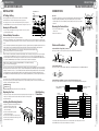
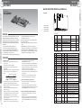
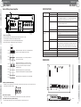
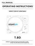
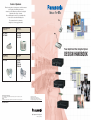
Colors of Speakers
When choosing speakers, it is important to consider the strucutre
or wood quality of the building or the interior.
As much as possible, Panasonic speakers have been designed
to harmonize with a variety of interiors.
Because building interiors tend to be predominantly white,
we have used it as the standard underlying tone.
To accentuate the mood of your interior,
simply choose the most appropriate shade.
Integrated White
Off White
(Munsell 10Y9/1)
(Munsell 5Y8.5/1)
WS-TN05N
WS-TN06N
WS-2330N
WS-2335N
WS-2360N
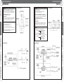
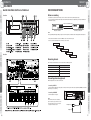
Power Amplifier & Mixer Integrated System
Ivory White
Light Gray
(Munsell 2.1Y7.7/1)
(Munsell N7)
WT-7015N
WT-610N
WT-615N
WT-H500N
WT-H600N
DESIGN HANDBOOK
* Due to printing irregularities, actual shades may vary slightly from the illustration.
Trademarks and registered trademarks
– Microsoft, and Windows are registered trademarks of Microsoft Corporation in the U.S. and other countries.
– SD logo is a trademark.
Important
– Safety Precaution: carefully read the operating instructions and installation manual before using this product.
• All TV pictures are simulated.
• Weights and dimensions are approximate.
• Specifications are subject to change without notice.
• These products may be subject to export control regulations.
DISTRIBUTED BY:
http://panasonic.net/pss/pa/
Printed in Japan (1N-775B)
1
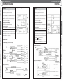
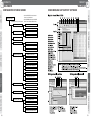
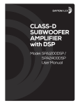
Concept
2
System Examples
3
Connections
4
Products
5
Block Diagrams
CONCEPT
P4 ~ P7
Booster Power Amplifier
WA-BA240N (240W)
Mixing Power Amplifier
WA-MA120N (120W)
Mixing Power Amplifier
SYSTEM EXAMPLES
WA-MA240N (240W)
P8 ~ P15
Sound Message Unit
WU-ZM001E
WU-ZS001E
Remote Microphone
WR-201E
CONNECTIONS
Surveillance Unit
TABLE
OF
CONTENTS
P16 ~ P43
PRODUCTS
P44 ~ P73
Remote Control Microphone
WR-210AE
BLOCK DIAGRAMS
2
P74 ~ P79
3
1
CONCEPT
CONCEPT
CONCEPT
CONCEPT
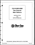
All-in-One Mixer and Amp
CONCEPT
SYSTEM EXAMPLES
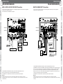
Background music and announcement transmission can be
transmitted independently to any of three zones, with
background music transmitted to one zone and
announcements transmitted to another zone.
*2-channel broadcast requires the optional WA-BA240N Booster Power Amplifier
Switch to on for 2-channel
Broadcast from Input 1
Surveillance Unit Slot
Attenuator Override
Broadcast Simultaneously To
Multiple Remote Areas
For example, facilities with multiple buildings can have a
WA-MA120N or WA-MA240N installed in each building. Via
the simultaneous broadcast BUS I/O connector, broadcasts
can be directed to selected all buildings at once.
Low Impedance Speaker
High Impedance Speaker
Program Broadcast
ZONE 3
(BGM)
Background
music
continue
ZONE 2
(BGM)
ZONE 2
(BGM)
ZONE 1
(BGM)
ZONE 1
(Message) Attention...
With the optional WU-ZM001E Sound Message Unit, an
SD memory card can be used to store MP3 data to be
broadcast for a week at specified days and times. The SD
memory card holds 100 messages.
Emergency
Equipment
DC+24V
Connect Telephone
Paging
CD/MD Player or Other Background Music Source
The optional WU-ZS001E Surveillance Unit checks at
preset intervals (or 24-hours a day) for overheating and
sound and speaker irregularities.
Basic Example
Priority Broadcast Feature Priorities are as follows.
Up To Four Remote Microphones
(1) Emergency announcement
Up to four (4) WR-210AE remote microphones can be used
to broadcast from remote locations. These remote
microphones can be used for individual, group, all-at-once or
simultaneous broadcast.
(2) Telephone paging, input 1, message from
Sound Message Unit
ZONE 3
[F3 Restaurants Floor]
(3) Remote microphone
Add Up To 30 Zones
Reliable Cooling
Depending on scale of application systems may include up to
ten (10) WA-MA120N or WA-MA240N mixing power
amplifiers for expansion to up to 30 zones.
Cooling fan control is provided by two thermal sensors
monitoring temperatures inside the case.
Energy Saving Design
1
2
3
This mixing power amplifier uses Class-H amplifier
technology developed by RAMSA, the Panasonic
Professional Audio Group, to minimize power consumption.
PRODUCTS
ZONE 2
(4) input 2, 3 and Line 1, 2
NO.1 (Master)
Backup Battery in Case of Power Failure
Troubleshooting
Message for ZONE 1 only,
and BGM continues for
ZONE 2 and 3.
PRODUCTS
Up to four (4) Remote Microphones
CONNECTIONS
CONNECTIONS
ZONE 3
(BGM)
Select Call Sign
(1) Rising 4 sounds, (2) Falling
4 sounds, (3) Two sounds, one time
SYSTEM EXAMPLES
2-channel Broadcast
The Public Address System Made it Easy.
CONCEPT
From the simplest to the most complex public address needs, the WA-MA120N
and WA-MA240N have what it takes. These mixing power amplifiers
combine multiple inputs with assigned priorities and call
signs to provide the flexibility required for applications
ranging from schools and business facilities, factory,
office and religious buildings. To ensure more
efficient and reliable communication, options including
program broadcasting and troubleshooting.
1
[F2 Apparel Floor]
Higher priority broadcasts preempt lower
priority broadcasts.
*When (2) and (4) occur simultaneously and inputs compete, mixing occurs.
Sound level can be adjusted.
ZONE 1
[F1 Grocery Floor]
Cable Extension
BLOCK DIAGRAMS
BLOCK DIAGRAMS
When you need to broadcast to distant locations, the optional Booster Power Amplifier allows you to extend the speaker cable as far as necessary.
NO.2 (Slave)
4
5
6
ZONE1
WA-MA120N
WA-MA240N
NO.10 (Slave)
28
ZONE2
29
30
WR-210AE
(up to 4 units)
4
WA-BA240N
WA-BA240N
* While there are no restrictions on attaching a WA-BA240N to your
network, sound quality may deteriorate at distant locations.
ZONE3
ZONES
5
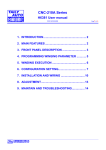
1
CONCEPT
CONCEPT
BASIC SYSTEM DIAGRAM
BASIC SYSTEM DIAGRAM
1
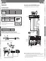
Mixing Power Amplifier (WA-MA120N/240N) Connection
CONCEPT
CONCEPT
Schematic diagram of Remote Microphone with Extension Unit (WU-RM205E) connected for announcements on 15 channels.
The illustration in the broken line frame shows how to connect more than one Remote Microphones to Mixing Power Amplifier.
Refer to this illustration for method of connecting up to 4 Remote Microphones.
Master
Extension Unit
WU-RM205E
Mixing Power Amplifier
WA-MA120N/240N
SYSTEM EXAMPLES
SYSTEM EXAMPLES
Remote Control
Microphone
WR-210AE
CONNECTIONS
CONNECTIONS
Amplifier (Master)
WA-MA120N/240N
Slave
Remote Control
Microphone
WR-210AE
Extension Unit
WU-RM205E
Amplifier (Slave 1)
PRODUCTS
PRODUCTS
WA-MA120N/240N
Amplifier (Slave 2)
BLOCK DIAGRAMS
BLOCK DIAGRAMS
WA-MA120N/240N
Amplifier (Slave 3)
WA-MA120N/240N
Important:
• Refer to page 38 and the Operating Instructions for the Amplifier for information on connecting Mixing Power Amplifiers
(WA-MA120N, WA-MA240N).
• Use a crimp connector to group wires together if you need to connect more than one wire to the terminal.
* Announcements can be made on a maximum of 30 channels by connecting 4 Extension Units, for a combination of 10 channels on the
Remote Microphone and 20 channels on the Extension Units.
6
Amplifier (Slave 4)
7
2
SYSTEM EXAMPLES
DEPARTMENT STORE
Department Store Outline
KEY POINT
• Remote-controlled Microphone Connection
• Cascade Connection
Allows remote microphones to be used for individual, group, allat-once emergency, and simultaneous 2-channel broadcasts.
Increases expansion capability to include all-zone broadcast to
separate facilities.
• Cascade Connection
• 2-channel Broadcast
Allows added amplifier capacity and additional speaker circuits.
Transmit a message only to the zone that needs it.
• Simple Emergency Broadcast Announcements
• Additional Amplifier Connection
Adding the optional Sound Message Unit to the master unit
allows broadcast of emergency instructions and also supports
turning off power to local amplifiers.
Supports additional amplifiers when changes in layout require
additional capacity.
• Other Features
Allows remote microphones to be used for individual, group, allat-once emergency, and simultaneous 2-channel broadcasts.
FEATURES
• Broadcasts background music.
• Mutes background music when remote microphone is in use.
• Extend the system throughout the entire building with
additional amplifiers.
• Broadcast of instructions at regular intervals.
• In an emergency, an emergency message is broadcast to all
zones.
Factory Outline
• Remote-controlled Microphone Connection
• Other Features
A chime is built into the master amplifier unit. The optional
Sound Message Unit supports configuration of systems for
regular broadcasts or simple emergency announcements.
FEATURES
• Priority Levels (1) to (4)
• Allows all-zone announcements from master amplifier to slave
amplifier.
• The remote microphone can be used for making
announcements to specific zones and all-zone announcements.
Individual announcements x 7 zones
General announcements x 1(All zones)
CONNECTIONS
System Diagram
2
SYSTEM EXAMPLES
A chime is built into the master amplifier unit. The optional
Sound Message Unit supports configuration of systems for
regular broadcasts or simple emergency announcements.
SYSTEM EXAMPLES
FACTORY
CONCEPT
CONCEPT
KEY POINT
CONNECTIONS
SYSTEM EXAMPLES
System Diagram
BLOCK DIAGRAMS
BLOCK DIAGRAMS
PRODUCTS
PRODUCTS
8
9
2
SYSTEM EXAMPLES
RESIDENCE
SCHOOL
Residence Outline
School Outline
KEY POINT
• Remote-controlled Microphone Connection
• Cascade Connection
Allows remote microphones to be used for individual, group, allat-once emergency, and simultaneous 2-channel broadcasts.
Normal: Transmits individually to specific amplifiers.
Emergency: All-zone announcement.
• Additional Amplifier Connection
• Remote-controlled Microphone Connection
When additional capacity is needed.
Allows remote microphones to be used for individual, group, allat-once emergency, and simultaneous 2-channel broadcasts.
• Other Features
A chime is built into the main amplifier unit. The optional Sound
Message Unit supports configuration of systems for regular
broadcasts or simple emergency announcements.
• Pages can be directed to individual zones.
• Broadcasts background music
• Chimes can be broadcast at regular intervals.
• In an emergency, an emergency message is broadcast to all
zones.
• WA-BA240N supplementary amplifier can be added for areas
where amplifier capacity is insufficient.
• Additional Amplifier Connection
Supports additional amplifiers when changes in layout require
additional capacity.
• Other Features
A chime is built into the master amplifier unit. The optional
Sound Message Unit supports configuration of systems for
regular broadcasts or simple emergency announcements.
FEATURES
• Normal usage (transmit to individual amplifiers).
Staff Room
Warden’s Room
Gymuasium Ridge
School Ridge
Dormitory Ridge
SYSTEM EXAMPLES
FEATURES
2
CONCEPT
CONCEPT
KEY POINT
SYSTEM EXAMPLES
SYSTEM EXAMPLES
• Emergency usage (all-zone announcement to whole facility).
BLOCK DIAGRAMS
PRODUCTS
BLOCK DIAGRAMS
System Diagram
PRODUCTS
10
System Diagram
Gymuasium Ridge
School Ridge
Dormitory Ridge
CONNECTIONS
CONNECTIONS
Staff Room
11
2
SYSTEM EXAMPLES
SHOPPING CENTER
Public Address Paging System
• 2-channel Broadcast
• Cascade Connection
Allows added amplifier capacity and additional speaker circuits.
A chime is built into the master amplifier unit. The optional
Sound Message Unit supports configuration of systems for
regular broadcasts or simple emergency announcements.
Transmit a message only to the zone that needs it.
• Remote- controlled Microphone Connection
Allows remote microphones to be used for individual, group, allat-once emergency, and simultaneous 2-channel broadcasts.
• Broadcasts background music.
• Mutes background music when remote microphone is in use.
• Extend the system throughout the entire building with
additional amplifiers.
• Broadcast of instructions at regular intervals.
• In an emergency, an emergency message is broadcast to all
zones.
Adding the optional Sound Message Unit to the master unit
allows broadcast of emergency instructions and also supports
turning off power to local amplifiers.
Paging System for Parking
• 2-channel Broadcast
• Remote- controlled Microphone Connection
Allows remote microphones to be used for individual, group, allat-once emergency, and simultaneous 2-channel broadcasts.
FEATURES
• Broadcasts background music.
• Mutes background music when remote microphone is in use.
• With additional amplifiers, broadcasts can reach the whole facility.
• In an emergency, an emergency message is broadcast to all
zones.
• Emergency input can turn off power to local amplifiers.
System Diagram
CONNECTIONS
System Diagram
Hotel Outline
• Simple Emergency Broadcast Announcements
Transmit a message only to the zone that needs it.
FEATURES
2
SYSTEM EXAMPLES
SYSTEM EXAMPLES
• Other Features
CONNECTIONS
KEY POINT
Allows remote microphones to be used for individual, group, allat-once emergency, and simultaneous 2-channel broadcasts.
Adding the optional Sound Message Unit to the master unit
allows broadcast of emergency instructions and also supports
turning off power to local amplifiers.
PRODUCTS
PRODUCTS
Shopping Center Outline
• Remote-controlled Microphone Connection
• Simple Emergency Broadcast Announcements
BLOCK DIAGRAMS
BLOCK DIAGRAMS
HOTEL
CONCEPT
CONCEPT
KEY POINT
12
SYSTEM EXAMPLES
13
2
SYSTEM EXAMPLES
COMPOUND BUILDING
Compoumd Building Outline
KEY POINT
Public Address Paging System for whole facility
Public Address Paging System
• 2-channel Broadcast
• 2-channel Broadcast
Transmit a message only to the zone that needs it.
Transmit a message only to the zone that needs it.
• Cascade Connection
• Cascade Connection
Allows added amplifier capacity and additional speaker units.
Allows added amplifier capacity and additional speaker circuits.
• Simple Emergency Broadcast Announcements
• Simple Emergency Broadcast Announcements
Adding the optional Sound Message Unit to the master unit
allows broadcast of emergency instructions and also supports
turning off power to local amplifiers.
Adding the optional Sound Message Unit to the master unit
allows broadcast of emergency instructions and also supports
turning off power to local amplifiers.
Paging System for Parking
Paging System for Waiting Room
• 2-channel Broadcast
• Remote-controlled Microphone Connection
Transmit a message only to the zone that needs it.
Allows remote microphones to be used for individual, group, allat-once emergency, and simultaneous 2-channel broadcasts.
• Cascade Connection
Allows added amplifier capacity and additional speaker circuits.
• Cascade Connection
Increases expansion capability to include all-zone broadcast to separate facilities.
FEATURES
• Mutes background music when remote microphone is in use.
• Emergency input turns off power to local amplifiers.
• Amplifier capacity can be increased by connecting additional amplifiers.
• Remote microphone can be used for separate broadcasts
(driver waiting room or parking garage).
• In emergencies, DC 24V input shuts down amplifiers.
• Background music broadcast to hallways and elevator lobbies.
• Mutes background music when remote microphone is in use.
• Emergency message is broadcast in response to emergency input.
• Paging outpatients waiting to see the doctor by next-in-queue numbers.
• Normal usage (Paging from individual amplifiers)
Reception <1>
Waiting Area <1> <2>
Reception <2>
Waiting Area <3> <4>
• All zone (Paging from one amplifier)
Reception <1> or <2>
Waiting Area <1> <2> <3> <4>
Public Addres Paging System for whole facility
System Diagram
Public Addres Paging System
Hospital Outline
CONNECTIONS
System Diagram
FEATURES
2
SYSTEM EXAMPLES
SYSTEM EXAMPLES
HOSPITAL
CONCEPT
CONCEPT
KEY POINT
PRODUCTS
PRODUCTS
CONNECTIONS
SYSTEM EXAMPLES
Paging System for Waiting Room
14
BLOCK DIAGRAMS
BLOCK DIAGRAMS
Paging System for Parking
15
3
CONNECTIONS
CONNECTIONS
WA-MA120N/WA-MA240N
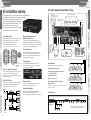
INSTALLATION
WA-MA120N/WA-MA240N
3
CONNECTIONS
VOLTAGE SELECTOR
switch
• Before plugging the AC power plug into the mains, make sure the VOLTAGE
SELECTOR switch on the back of the Amplifier is in the proper position.
• The factory preset is 220 V to 240 V. The Amplifier will not operate correctly if the
VOLTAGE SELECTOR is set to 220 V to 240 V while the AC voltage is 110 V to 120 V.
SYSTEM EXAMPLES
SYSTEM EXAMPLES
Cables and Connectors
Cable with XLR-3-12 Type (Male) Connector
Battery Capacity [AH] = Amplifier Normal DC Consumption Current [A]* x Required Operating Time [H]
Use this type of cable to connect to inputs 1 through 3. Use a connector that is wired pin 2 hot.
* Based on IEC60065 standards. Refer to the SPECIFICATIONS (page 48).
• When connected to an external battery, the Amplifier will automatically switch to the battery power supply once the AC power supply is
cut off by turning off the POWER switch or due to power cut. The battery power is not cut off even when the POWER switch on the
back of the Amplifier is turned off. The battery power consumption continues even when both the OPERATE and the POWER switches
are off and the OPERATE indicator remains lit amber. Use the formula below to determine the battery life.
Screw
Spring washer
2
1
3 (Cold)
Battery Life [H] = Battery Capacity [AH] ÷ Amplifier Standby DC Consumption Current [A]*
H (Hot)
2 (Hot)
1 (Ground) G (Ground)
3
C (Cold)
* Please refer to the SPECIFICATIONS (page 48).
To save the power of the battery, switch off both the POWER and the OPERATE, remove the battery if the Amplifier is not in use for a long period.
• No battery power will be consumed only if the AC power is connected. And the Amplifier has no built-in battery charger. Note that the battery
discharges even when it is not in use, so observe the battery's instructions and check the battery periodically. Be sure to remove the battery
from the Amplifier before charging. And charge the battery properly according to the instructions of the battery and the battery charger.
• The Amplifier operates normally with the battery voltage over 21 V, and audio output malfunction may occur if the voltage is lower than 21 V.
Cable with D-sub 9 pin (Male) Connector on both Ends (inch-pitch screw)
Use this type of cable to link the ALL CALL BUS connectors when connecting multiple Amplifier units together.
D-sub 9 pin (Male) connector
(inch-pitch screw)
Take care to ensure proper battery polarity and to avoid shorts while working.
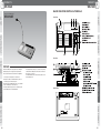
Rack Mounting
Precautions
Signal Name
Amplifier B
ALL CALL BUS IN
Pin No.
GND
6
Blank
Panel
Control Terminal 5
6
Shielded Cable
7
8
7
8
9
4
9
5
Control Terminal
Control Terminal
8
9
ALL CALL BUS HOT
ALL CALL BUS COLD
3
4
Signal Name
Control Terminal
GND
2
3
8
5
6
7
4
9
1
2
3
GND 4
GND
6
7
Pin No.
1
2
Control Terminal 3
Control Terminal
Pin No.
GND
GND
5
• Use a straight cable with all pins wired. Be sure to use shielded cable only for audio signal connections.
• General RS422 cable can be used for short distances of a few metres.
Control Terminal
BLOCK DIAGRAMS
ALL CALL BUS COLD
Pin No.
1
ALL CALL BUS HOT 2
Blank
Panel
D-sub 9 pin (Male) connector
(inch-pitch screw)
Amplifier A
ALL CALL BUS THRU
Control Terminal 1
Installing Rack Mounting Brackets
• Installing the supplied rack mounting brackets lets you
configure the Amplifier for rack mounting.
1. Remove the screws (M5 x 16) from both
sides of the Amplifier.
2. Use the four screws (M5 x 16) to attach
the rack mounting brackets.
• Also remove the four rubber feet on the bottom of the
Amplifier by using a flat blade screwdriver to pry out the
pins that hold the feet in place.
Hot
PRODUCTS
WA-MA120N: 15 A
WA-MA240N: 30 A
• If the fuse blow, replace it with a fuse that is the same shape and capacity. The wrong type of fuse
will be prone to blowing even under normal conditions, and creates the risk of danger if the
Amplifier malfunctions.
Use this type of cable to connect to LINE 1, LINE 2, REC OUT, LINE OUT, INPUT D-OUT, and INS IN/THRU/OUT.
Ground
• Refer all work related to the installation and maintenance of the external battery to qualified service personnel or system installers.
• Be sure to turn off power (AC) before installing or removing a battery. To protect the battery, provide one of the fuses shown below between
the battery + terminal and the Amplifier's + terminal.
Replacing the Fuse
Cable with RCA Pin Plug
CONNECTIONS
CONNECTIONS
PA
External Battery Precautions
Note the following precautions when using an external battery.
• Make sure the external battery is a 24 V Lead Acid battery (or two 12 V batteries in series connection). Panasonic Corporation holds
no responsibility for any Amplifier fault operation or other inconveniences resulting from using any other batteries except that indicated
above.
• Use the formula below to determine the battery capacity that is necessary to support the amount of operating time required. Note, however,
that the actual amount of operation time provided by a battery varies greatly in accordance with the Amplifier's signal output Level.
Cautions:
PRODUCTS
PA
1. Loosen the screw that secures the
terminal cover.
2. Remove the terminal cover.
• Do not use UPS (Uninterruptible Power Supply) as backup in case of AC power cut.
Use external batteries instead.
BLOCK DIAGRAMS
OUT
Removing the Terminal Cover
Backup for AC Power Cut
16
PA
IN
• The Amplifier's output power cannot be increased if multiple Amplifiers (or WA-BA240N Booster Power
Amplifier) are inputting and outputting the same signal "in parallel operation" because it will short
circuit. Absolutely do not connect the Amplifiers together in parallel operation, doing so may result in a
malfunction.
CONCEPT
CONCEPT
Amplifier
Important:
AC Voltage Setting
17
WA-MA120N/WA-MA240N
WA-MA120N/WA-MA240N
LINE1,2, INPUT2,3, REC OUT, INS IN/OUT Connections
EMG, TEL PAGING, INPUT1 Connections
• Use the connections shown below for a microphone or recording/playback equipment, effect device that is not equipped with
activation control (no-voltage make contact).
• For information about connecting INPUT1, refer to page 19.
• Use the connections shown below for emergency announcement equipment or PBX, microphone that is equipped with
activation control (no-voltage make contact).
WA-MA120N
or
WA-MA240N
BGM Player
(CD player, etc.)
Effect Device
(graphic equalizer, etc.)
Microphone, etc.
Microphone, etc.
Audio Signal Source Equipment
(IC player, etc.)
Recording/
Playback Equipment
(cassette deck, etc.)
Emergency Announcement
Equipment
CONNECTIONS
CONNECTIONS
WA-MA120N
or
WA-MA240N
3
SYSTEM EXAMPLES
SYSTEM EXAMPLES
CONNECTIONS
CONCEPT
CONCEPT
3
CONNECTIONS
Talk Switch (no-voltage make contact)
BLOCK DIAGRAMS
• Change the INPUT1-3 MIC/ LINE switches setting in accordance with the equipment being connected.
• When connecting an effect device, remove the plug inserted in the RCA pin jack.
• Turn the INPUT1-3 +16 V ON/OFF switches on only when using an electret condenser microphone.
CALL SIGN Falling Switch
(no-voltage make contact)
• Change the INPUT1 MIC/ LINE switches setting in accordance with the equipment being connected.
• Turn the INPUT1 D-OUT switch on when the INPUT 1 signal is being output from INPUT D-OUT for 2-channel announcement.
• Be sure to connect the connected device's no-voltage make contact terminal to each activation control terminal [CNT]. If they
are not connected, announcement priority control will not work or the audio signal of the equipment will not be output.
• When using a call tone, be sure to make contact with each input equipment's not-voltage make contact and then activate the
call tone. The call tone will not be announced if it is activated first.
• Turn the INPUT1 +16 V ON/OFF switch on only when using an electret condenser microphone.
Important:
Important:
• Leaving this setting on when for any other type of connection will cause malfunction of the connected device or equipment.
• Changing this setting also can cause noise, so be sure to use the INPUT1-3 knobs on the front of the Amplifier to reduce volume before
changing this setting.
• Leaving this setting on when for any other type of connection will cause malfunction of the connected device or equipment.
• Changing this setting also can cause noise, so be sure to use the INPUT1 knob on the front of the Amplifier to reduce volume before changing
this setting.
BLOCK DIAGRAMS
18
PBX, etc.
PRODUCTS
PRODUCTS
CALL SIGN Rising Switch
(no-voltage make contact)
19
CONNECTIONS
WA-MA120N/WA-MA240N
WA-MA120N/WA-MA240N
Remote Microphone (WR-210AE) Connection
Speaker Connection
• Up to four Remote Microphone units can be connected. For multiple connections, priority connection between Remote
Microphones is required. For more information, consult the operating instructions of the Remote Microphone.
• Use the connections shown below for connecting high-impedance or low-impedance loudspeakers.
Caution:
High-impedance and low-impedance loudspeakers cannot be connected at the same time. When using high-impedance loudspeakers, use
either 100 V or 70 V.
3
CONCEPT
CONCEPT
3
CONNECTIONS
WA-MA120N
or
WA-MA240N
WA-MA120N
or
WA-MA240N
SYSTEM EXAMPLES
SYSTEM EXAMPLES
Important 1
Monitor,
etc.
Zone 1
Important 1
Important 2
Zone 2
Connect to
any terminal
Important 3
Low-impedance Loudspeakers
(up to 4Ω)
CONT
CKO
High-impedance Loudspeakers
(up to the impedance shown in the table below)
Important 1:
When you want high-impedance loudspeaker output to by 70 V, change the position of the jumper as shown in the illustration. The factory
preset is 100 V.
Important 2:
Make sure that the parallel composition impedance of high-impedance loudspeakers does not fall below the values shown in the table below.
Important 1:
Make this connection if you want to use call tones.
Important 2:
To perform 2-channel announcement from the Remote Microphone, connect the CALL terminal to any one of the C4 to C10 terminals of the
Remote Microphone. The individual switch (4-10) on the Remote Microphone that corresponds to the terminal number you connect to can be
used to switch to zone 1 interrupt during 2-channel announcement.
Conditions
Composition impedance
for one zone
Minimum Composition Impedance
WA-MA120N
WA-MA240N
100 V
70 V
100 V
83 Ω
42 Ω
42 Ω
(120 W)
(120 W)
(240 W)
Speakers connected to
ZONE 1 or DIRECT OUT
only
Speakers connected to
multiple zones and DIRECT
OUT, and use
simultaneously
70 V
21 Ω
(240 W)
Composition impedance
of all zones
83 Ω
(120 W)
21 Ω
(240 W)
42 Ω
(120 W)
42 Ω
(240 W)
Important 3:
Important 3:
If you want the Amplifier to enter the operation mode when activation control is imposed from the Remote Microphone, branch from the cable
connected to the Remote Microphone's CONT terminal and connect to the Amplifier's OPERATE ON terminal.
Make sure that the parallel composition impedance of low-impedance loudspeakers does not fall below 4 Ω. Up to two 8 Ω speakers or four
16 Ω speakers can be connected in parallel.
BLOCK DIAGRAMS
• Confirm that the -22dBV (RM), -65dBV (MIC) switch is set to -22dBV (RM). If it isn't change the switch setting to -22dBV (RM).
Speaker Connection
Method
PRODUCTS
BLOCK DIAGRAMS
Important 2
C3
C4 to 10
C2
C1
CALL SIGN DOWN
CALL SIGN UP
PRODUCTS
LINE OUT H
LINE OUT C
DC 24V
0V
20
Zone 3
Remote Microphone
(WR-210AE)
CONNECTIONS
CONNECTIONS
Important 3
21
3
CONNECTIONS
CONNECTIONS
WA-MA120N/WA-MA240N
WA-MA120N/WA-MA240N
• For 2-channel broadcast announcement, connect the WA-BA240N as shown below.
Amplifier
ATT OVERRIDE
IN B
To external attenuator
3-wire connection attenuator
WA-MA120N
or
WA-MA240N
(H)
All-zone
announcement ON
OUT
(H)
(C)
IN A
DIRECT OUT
(OVERRIDE)
(C)
H
C
H
C
H
ZONE 2
C
C
ZONE 1 External Attenuator
H
OVERRIDE
C
ZONE 2 External Attenuator
H
OVERRIDE
C
ZONE 3 External Attenuator
Important
Connecting to Override External Attenuation during All-zone Announcement
(Using 4-wire connection)
PRODUCTS
To external attenuator
Amplifier
4-wire connection attenuator
ATT OVERRIDE
IN B
All-zone
announcement ON
(H)
OUT
(H)
(C)
+
–
ZONE 1
H
C
H
ZONE 2
C
ZONE 3
H
C
(C)
(+24V)
(0V)
H
C
+
–
H
C
+
–
H
C
+
–
ZONE 1 External Attenuator
Relay Power
• Use the gold plated plug (accessories of WA-BA240N) when connecting to LINE IN of WA-BA240N.
• Set the 2-channel announcement volume using the LEVEL knob of WA-BA240N.
Important:
ZONE 2 External Attenuator
Relay Power
If you want the WA-BA240N to turn on together with the WA-MA120N or WA-MA240N, connect the OPERATE LINK terminal to the OPERATE
ON terminal of the WA-BA240N.
Note:
ZONE 3 External Attenuator
Relay Power
If other amplifiers except WA-BA240N are required, select appropriate power amplifier rated output in accordance with ZONE1 speaker
impedance.
BLOCK DIAGRAMS
BLOCK DIAGRAMS
IN A
DC +24V OUT
PRODUCTS
WA-BA240N
CONNECTIONS
H
ZONE 3
H
OVERRIDE
C
WA-MA120N
or
WA-MA240N
22
SYSTEM EXAMPLES
SYSTEM EXAMPLES
WA-MA120N
or
WA-MA240N
ZONE 1
CONNECTIONS
2-channel Broadcast Announcement Connection
CONCEPT
CONCEPT
Connecting to Override External Attenuation during All-zone Announcement
(Using 3-wire connection)
3
23
CONNECTIONS
WA-MA120N/WA-MA240N
WA-MA120N/WA-MA240N
Battery Connection
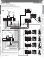
Zone Expansion Connection
• Make sure the external battery is a 24 V Lead Acid battery (or two 12 V
batteries in series connection). Panasonic Corporation holds no
responsibility for any Amplifier fault operation or other inconveniences
resulting from using any other batteries except that indicated above.
• Use the formula below to determine the battery capacity that is
necessary to support the amount of operating time required. Note,
however, that the actual amount of operation time provided by a battery
varies greatly in accordance with the Amplifier's signal output level.
• You can expand the number of zones using multiple Amplifier units.
• The illustration below shows the concept behind zone expansion. When connected this way the master Amplifier uses all
circuits but additional Amplifiers (Slave 1, 2 etc.) only use the built-in power amplifiers and zone output. This provides the
maximum rated output of the Amplifier for each group of three zones.
• The maximum number of Amplifiers (including the master and slaves) is 10, which means there can be to 30 zones.
3
CONCEPT
CONCEPT
3
CONNECTIONS
Important 1
* Based on IEC60065 standards. Refer to SPECIFICATIONS (page 48).
Amplifier (Master)
Caution:
Be sure to turn off power (AC) before installing or removing a battery. To
protect the battery, provide one of the fuses shown below between the battery
+ terminal and the Amplifier's + terminal.
WA-MA120N: 15 A
WA-MA240N: 30 A
Caution
+
Important 2
Connect to
each input device
-
Important 3
To zone 1 to 3 speakers
Important 1
Take care to ensure proper battery polarity and to avoid shorts while working.
DC+24V
SYSTEM EXAMPLES
SYSTEM EXAMPLES
Battery Capacity [AH] = Amplifier Normal DC Consumption
Current [A]* x Required Operating Time [H]
Operation On/Off Control
The Amplifier can be put into the operation mode externally by no-voltage make contact. The Amplifier can also cause other linked
equipment to enter operation mode when it enters the operation mode.
Amplifier (Slave 1)
Important:
• In order for external operation control to be performed, the POWER switch on the back of the Amplifier must be ON, and the OPERATE switch
on the front must be OFF so the Amplifier is in the non-operation (standby) mode. The Amplifier's current operation/non-operation mode is
determined by the relationship between external control (no-voltage make contact) status and the Amplifier's OPERATE switch setting.
Important 2
Important 3
To zone 4 to 6 speakers
Important 1
Amplifier's OPERATE
switch position
Not Depressed (OFF)
Depressed (ON)
CONNECTIONS
CONNECTIONS
• Operation On Control and Operation Link Control
No-voltage make contact
Make
Break
Operation Mode Non-operation Mode
Operation Mode Operation Mode
Other device power on link
No-voltage make contact
• Operation Off Control
Important 2
The Amplifier can be put into the non-operation (standby) mode externally by no-voltage make contact. Use this capability when you want
to terminate business announcements from this Amplifier during announcements from external emergency announcement equipment.
Important:
• All connect the ALL CALL BUS connectors as shown in the illustration. All-zone announcement will not be possible if these
connectors are not connected.
Important 1:
On all of the Amplifiers, set the UNITS SET switches to the total number of Amplifiers.
Example: In the case there is one master and four slaves, set the UNITS SET switches of all of the Amplifiers to 5.
Amplifier's OPERATE
switch position
Not Depressed (OFF)
Depressed (ON)
No-voltage make contact
24
To zone 7 to 9 speakers
To Amplifier (Slave 3)
No-voltage make contact
Make
Break
Non-operation Mode Non-operation Mode
Non-operation Mode Operation Mode
Important 2:
Never remove the plug from the RCA pin jack of the master Amplifier. No sound will be output in any of the zones
if you do. For all of the slave units, remove the plug and then do the connections.
Important 3:
Connect when you want operation control activated on all of the Amplifiers. For the connection shown in the illustration here, entering the
operation mode on the master also puts all of the slaves into the operation mode as well. Note, however, that the slaves must be in the standby
mode before the master goes into the operation mode.
For information about operation on/off control, see page 24.
BLOCK DIAGRAMS
BLOCK DIAGRAMS
• In order for operation off control to be performed, the POWER switch on the back of the Amplifier must be on, and the OPERATE switch on the
front must be ON so the Amplifier is in the operation mode. The Amplifier's current operation/non-operation mode is determined by the
relationship between external control (no-voltage make contract) status and the Amplifier's OPERATE switch setting.
Important 3
PRODUCTS
PRODUCTS
Amplifier (Slave 2)
25
3
CONNECTIONS
CONNECTIONS
WA-MA120N/WA-MA240N
WA-MA120N/WA-MA240N
3
Normal operation from individual zone announcement
device (BGM, non-priority microphone)
Inter-area all-zone announcement from all-zone
announcement device (priority microphone and remote
control microphone, PBX, non-priority announcement device)
Area 1
Area 1
Amplifier
BGM
Mixing
Mixing
BGM
Built-in
Power Amplifier
Microphone
To Area 1, Zone 1 to 3 speakers
Important 1
Mixing
Built-in
Power Amplifier
Amplifier (Area 2)
Remote
Microphone
PBX
PBX
ALL CALL BUS THRU
Area 2
ALL CALL BUS THRU
Area 2
Amplifier
BGM
Mixing
Amplifier
Mixing
BGM
Built-in
Power Amplifier
Mixing
ALL CALL BUS IN
Mixing
Built-in
Power Amplifier
Microphone
Remote
Microphone
Amplifier (Area 3)
PBX
ALL CALL BUS THRU
Area 3
Emergency
Announcement
Equipment
ALL CALL BUS THRU
Area 3
Amplifier
BGM
Mixing
Amplifier
ALL CALL BUS IN
Mixing
BGM
Built-in
Power Amplifier
Remote
Microphone
Mixing
ALL CALL BUS IN
Built-in
Power Amplifier
Microphone
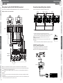
Important 1:
Up to 10 Amplifiers, 10 areas
On all of the Amplifiers, set the UNITS SET switches to the total number of Amplifiers.
Example: In the case there is one master and four slaves, set the UNITS SET switches of all of the Amplifiers to 5.
PBX
ALL CALL BUS THRU
Up to 10 Amplifiers, 10 areas
Important 2:
Connect when you want operation control activated on all of the Amplifiers. For the connection shown in the illustration here, entering the
operation mode on the master also puts all of the slaves into the operation mode as well. Note, however, that the slaves must be in the standby
mode before the master goes into the operation mode.
For information about operation on/off control, see page 24.
BLOCK DIAGRAMS
ALL CALL BUS THRU
To Area 3, Zone 1 to 3 speakers
Amplifier (to Area 4)
Mixing
Remote
Microphone
PBX
Important 2
Connect to
each input device
PRODUCTS
Emergency
Announcement
Equipment
Microphone
To Area 2, Zone 1 to 3 speakers
Important 1
ALL CALL BUS IN
Microphone
Important 2
Connect to
each input device
CONNECTIONS
CONNECTIONS
Mixing
Microphone
PBX
PRODUCTS
Important 2
Amplifier
Remote
Microphone
BLOCK DIAGRAMS
Amplifier (Area 1)
Connect to
each input device
Remote
Microphone
26
Important 1
SYSTEM EXAMPLES
SYSTEM EXAMPLES
• When Amplifiers are being used for separate operation in multiple areas, they can be connected using the ALL CALL BUS to
allow all-zone announcement from one area to all of the other areas.
• The signal paths of an inter-area all-zone announcement during normal operation are shown below. In addition, each input
device that is capable of all-zone announcement has a priority level within the same area and between different areas. During
an emergency announcement from the emergency announcement equipment in Area 2 of the illustration below, for example,
all-zone announcement from any PBX or Remote Microphone from areas 1 through 3 is disabled. When two devices have the
same priority, their input is mixed and announced to all zones. In the illustration below, for example, two PBX or two Remote
Microphones can be used to announce from different areas to all zones.
• Inter-area all-zone announcement can be configured for up to 10 Amplifiers and 10 areas.
CONCEPT
CONCEPT
Inter-area All-zone Announcement Connection
27
WA-BA240N
WA-BA240N
Line-level Equipment Connection
Speaker Connection
• Connect external devices (e.g. pre-amplifiers) to the LINE IN jack. The following illustration is a connection example with the
Mixing Power Amplifier (WA-MA120N or WA-MA240N).
• Be sure to use the gold plated plugs (accessories) when using the LINE IN jack and/or the LINE THRU jack.
• Use the connections shown below for connecting high-impedance or low-impedance loudspeakers.
WA-MA120N
or
WA-MA240N
Caution:
High-impedance and low-impedance loudspeakers cannot be connected at the same time. When using high-impedance loudspeakers, use
either 100 V or 70 V.
3
SYSTEM EXAMPLES
SYSTEM EXAMPLES
CONNECTIONS
CONCEPT
CONCEPT
3
CONNECTIONS
Main System
Important 1 High-impedance
Loudspeakers (42 Ω or 21 Ω)
WA-BA240N
Monitor System
CONNECTIONS
CONNECTIONS
Important
PRODUCTS
PRODUCTS
Important 2 Low-impedance
Loudspeakers (up to 4 Ω)
LINE IN
LINE THRU Amplifier (WA-BA240N, etc.)
LINE IN
28
• Refer to the Operating Instructions of WA-MA120N or WA-MA240N for input and output connection in the Main System.
And refer to the next page for method of connecting loudspeakers in the Monitor System.
• Connect the LINE THRU when you want the output of the equipment connected to the LINE IN jack to be input to other
equipment as well.
Important:
The LINE THRU jack connects directly without going through the LINE IN jack's internal circuitry.
Consequently, the load from the viewpoint of the line-level equipment is the parallel composition value of the Amplifier's input impedance
(100 kΩ) and the input impedance of the equipment connected after the LINE THRU jack. Ensure that the input impedance parallel
composition value is not less than the matching load impedance of the line equipment.
Important 1:
Make sure that the parallel composition impedance of the high-impedance loudspeakers does not become less than 42 Ω in the case of 100 V,
or less than 21 Ω in the case of 70 V.
Important 2:
Make sure that the parallel composition impedance of low-impedance loudspeakers does not fall below 4 Ω. Up to two 8 Ω speakers or four 16 Ω
speakers can be connected in parallel.
BLOCK DIAGRAMS
BLOCK DIAGRAMS
LINE THRU Amplifier (WA-BA240N, etc.)
29
CONNECTIONS
WA-BA240N
WA-BA240N
Battery Connection
• Connecting power amplifier output for high-impedance loudspeakers as shown below makes it possible to expand the number
of speakers through the Amplifier.
• The following illustration is a connection example with the Mixing Power Amplifier (WA-MA120N or WA-MA240N).
• Make sure the external battery is a 24 V Lead Acid
battery (or two 12 V batteries in series connection).
Panasonic Corporation holds no responsibility for any
Amplifier fault operation or other inconveniences
resulting from using any other batteries except that
indicated above.
• Use the formula below to determine the battery
capacity that is necessary to support the amount of
operating time required. Note, however, that the
actual amount of operation time provided by a battery
varies greatly in accordance with the Amplifier's
signal output level.
SYSTEM EXAMPLES
WA-MA120N
or
WA-MA240N
Battery Capacity [AH] = Amplifier Normal DC
Consumption Current [A]* x Required Operating Time [H]
Caution
* Based on IEC60065 standards. Refer to SPECIFICATIONS (page 53).
Caution:
Be sure to turn off power (AC) before installing or removing a battery. To protect the battery, provide
a 30 A fuse between the battery + terminal and the Amplifier's + terminal. Take care to ensure proper
battery polarity and to avoid shorts while working.
–
DC+24V
Operation On/Off Control
• Operation On Control and Operation Link Control
The Amplifier can be put into the operation mode externally by no-voltage make contact. The Amplifier can also cause other
linked equipment to enter operation mode when it enters the operation mode.
Important
Important:
In order for external operation control to be performed, the POWER switch on the back of the Amplifier must be on, and the OPERATE switch
on the front must be OFF so the Amplifier is in the non-operation (standby) mode. The Amplifier's current operation/non-operation mode is
determined by the relationship between external control (no-voltage make contact) status and the Amplifier's OPERATE switch setting.
Amplifier's OPERATE
switch position
PRODUCTS
WA-BA240N
No-voltage make contact
Make
Break
Operation Mode Non-operation Mode
Operation Mode
Operation Mode
Other device power on link
No-voltage make contact
• Operation Off Control
PRODUCTS
Not Depressed (OFF)
Depressed (ON)
CONNECTIONS
WA-BA240N
CONNECTIONS
+
SYSTEM EXAMPLES
100 V Input Connection
3
CONCEPT
CONCEPT
3
CONNECTIONS
The Amplifier can be put into the non-operation (standby) mode externally by no-voltage make contact.
30
In order for operation off control to be performed, the POWER switch on the back of the Amplifier must be on, and the OPERATE switch on the
front must be ON so the Amplifier is in the operation mode. The Amplifier's current operation/non-operation mode is determined by the
relationship between external control (no-voltage make contract) status and the Amplifier's OPERATE switch setting.
• ZONE 2, ZONE 3 or DIRECT OUT terminals are also available for output of WA-MA120N or WA-MA240N.
• To perform operation link control, interconnect the OPERATE ON/LINK/OFF terminals of the various devices.
For information about operation on/off control, see page 31.
• Use amplifiers that support high-impedance loudspeakers when using amplifiers except WA-MA120N or WA-MA240N.
Amplifier's OPERATE
switch position
Not Depressed (OFF) Non-operation Mode Non-operation Mode
Non-operation Mode Operation Mode
Depressed (ON)
Important:
When the rated output of the power amplifier connected to the Amplifier's 100 V terminal is less than 100 V, the output of the Amplifier will be
lower than the rated output.
No-voltage make contact
Make
Break
BLOCK DIAGRAMS
BLOCK DIAGRAMS
Important:
No-voltage make contact
31
3
CONNECTIONS
CONNECTIONS
WU-ZM001E
WU-ZM001E
7. Replace the Amplifier's top cover.
• Be sure to turn off power before connecting or configuring settings.
Be sure to turn off the device supplying power to the Sound Message Unit.
Leaving power supplied creates the risk of electric shock and damage to equipment.
Heat sink
Installing the Sound Message Unit to the mixing power amplifier and
configuring connections
4. Put 3 wiring cables on the heat sink and keep
them there.
Under this condition, push this unit all the way in and fix
this unit to the Amplifier with the 2 screws, which are
removed in step 2.
Connecting MSG Control Input
MSG Control Input is connected as shown below.
Clamp here
CN12
CONNECTIONS
CONNECTIONS
CN14
5. Connect the 3 cables to CN1 and CN2 on the
back of this unit, and to CN200 on the side of
this unit. Then clamp the cables as shown
below with the cable clamp, which is installed
on this unit. (The cable clamp is made of metal
and shielded with black vinyl.)
SYSTEM EXAMPLES
SYSTEM EXAMPLES
Fix the Amplifier's top cover with the screws, which Are
removed in step1.
Warning:
CONCEPT
CONCEPT
CONNECTIONS AND SETTINGS
1. Remove the top cover of the mixing power
amplifier (Amplifier).
3
CN6
Cable clamp
CN12
2. Remove the front blank panel from the Amplifier.
CN200CN1 CN2
CN6
Cable clamp
Heat sink
Cable clamp
No-voltage make contact
Note:
3. Remove the cable connected to CN14 on the main
board of the Amplifier.
32
No-voltage make contact
6. Fasten the top of the Sound Message Unit and
the Amplifier's frame with two screws
(provided).
No-voltage make contact
Standardized clock
(Radio synchronized clock,etc.)
CN14
CN12
CN6
Warning:
Be cautious not to get your finger clamped when inserting this unit
into the Mixing Power Amplifier.
BLOCK DIAGRAMS
BLOCK DIAGRAMS
Connect two internal wiring cables (accessories)
separately to CN12 and CN6 on the Amplifier's main
board.
Uplift the front panel side of this unit when inserting it into the
Amplifier. Or else, the cable clamp on the top of this unit may make
a hindrance against inserting
PRODUCTS
PRODUCTS
No-voltage make contact
33
CONNECTIONS
WU-ZS001E
3
WU-ZS001E
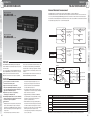
SURVEILLANCE I/F Connector
Example Application: (1)
– Switch Trigger/Status Indication
SURVEILLANCE I/F Connector
Example Application: (2)
– Backup Amplifier Connection
After connecting to an external line as shown below, the switches can be used
to trigger various operations, while indicators can be used to determine the status of the amplifier.
After connecting to an external line as shown below, the system can be configured to switch automatically to a backup amplifier
whenever a fault occurs on this amplifier.
Remove the jumper
CONCEPT
CONCEPT
3
CONNECTIONS
Pin No.12 PA SIGNAL FAULT
(Refer to page 63 for detailed information.)
SURVEILLANCE I/F Connector
1
UNITS SET
1 2 3 4 5 6 7 8 910
TEL
PAGING
ALL CALL
BUS IN
ALL CALL
BUS THRU
SURVEILLANCE I/F
RM
SP LINE
CHECK
/SETTING
ON
OFF
0
10
0
-22dBV(RM)
AMBER-NO SETTING
GREEN-SETTING COMPLETED
CLOCK ADJ CONT
RM
WA-MA120N
10kΩ
ALL CALL
or H C G CALL BC
WA-MA240N
Short
5kΩ
CONNECTION
NO.1:GND
NO.2:HOT
NO.3:COLD
1
ZONE 1
INPUT D-OUT
0dBV 10kΩ
-65dBV(MIC)
D-OUT
OFF ON
INPUT 1
CNT G NC NC NC NC
14
5
4
ZONE
3
2
1
GROUND
FAULT
10
CAUTION
RISK OF ELECTRIC
SHOCK.DO NOT OPEN
25
SP LINE FAULT
SETTING
STATUS
SYSTEM EXAMPLES
SYSTEM EXAMPLES
13
LINE 2
LINE 1
-22dBV 10kΩ -22dBV 10kΩ
RM DC
/DC OUT
T1AL
OPTION
DC+24V MAX200mA
MSG EMG1 EMG2 CLK ADJ.
Z1 Z2 Z3 G CNT G CNT G CNT G CNT G NC
VOLTAGE
SELECTOR
110V-120V
RED-SHORT
AMBER-OPEN
220V-240V
SIGNAL
GND
AC IN
POWER
ON
OFF
MAKE SURE THE COMBINED SPEAKER IMPEDANCES
ARE 83Ω OR MORE THAN 4Ω
REC OUT
INS OUT
0dBV 10kΩ 0dBV 10kΩ
LINE OUT
0dBV 10kΩ
NC
SP
SP
0V
OPERATE ON
CNT
G
K2
SP
K1
SP
DIRECT OUT
ZONE 1 CALL IN
ATT OVERRIDE
NC NC
IN A IN B OUT
(C) 100V (H) 70V
H
C
H
C
OPERATE LINK
OPERATE OFF
ZONE 3
ZONE 2
ZONE 1
NC NC NC NC
CNT
G
CNT
G
H
C
H
C
H
C
DC +24V OUT
MAX 200mA
+
DC +24V IN
+
+16V
321
ZONE 2
SP LINE REFERENCE
SETTING ACTIVATION
MIC
ON
OFF
LINE
INS IN
0dBV 100kΩ
INS THRU
CONNECTIONS
CONNECTIONS
ZONE 3
External relay
SP LINE CHECK
ACTIVATION
Open
ZONE 1
ZONE 2
Important
PRODUCTS
PRODUCTS
ZONE 3
INPUT
GROUND FAULT
NC
PA SIGNAL FAULT
IN
SER.No.
0V
VOLTAGE
SELECTOR
LEVEL
0dBV 100kΩ
WA-BA240N
110V-120V
0
POWER
220V-240V
ON
10
OFF
MAKE SURE THE COMBINED SPEAKER IMPEDANCES
ARE 42 Ω OR MORE THAN 4Ω
NC
COMM FAULT
SP
4Ω
OPERATE ON
CNT
G
CHECKING / SETTING BUSY
REFERENCE ERROR
Important:
SP
0V
NC
OPERATE LINK
CNT
G
SP
100V
NC
OPERATE OFF
CNT
G
SP
70V
NC
NC
NC
NC
NC
NC
NC
NC
NC
NC
NC
NC
NC
NC
NC
NC
NC
NC
NC
BLOCK DIAGRAMS
BLOCK DIAGRAMS
PA TEMP FAULT
LINE
THRU
CAUTION
RISK OF ELECTRIC
SHOCK.DO NOT OPEN
NC
100V
Use a 30 VDC 3 A relay or a 250 VAC 3 A relay or greater.
34
35
3
CONNECTIONS
CONNECTIONS
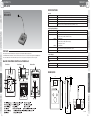
WR-210AE
WR-210AE
3
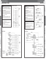
Mixing Power Amplifier (WA-MA120N/240N) Connection
CONNECTIONS
Refer to the following table to determine the number of Remote Microphones that can be connected to the PA systems.
PA System Name
Number of devices that can be connected
Name
Type
Remote Microphone (WR-210AE)
Extension Unit (WU-RM205E)
Mixing Power Amplifier WA-MA120N
4
4*
WA-MA240N
4
4*
*A maximum of 4 Remote Microphones can be connected to each WR-210AE.
Cable Diameters
Cable Lengths
Shielded cable
Control cable
C
WR-210AE
200 m or less
500 m or less
0.5 mm2 (AWG20) to 1.25 mm2 (AWG16)
ø0.8 mm (AWG20) to
ø1.2 mm (AWG16)
ø1.2 mm (AWG16)
10 9
8
7
6
CALL SIGN
5
4
3
2
1 DOWN UP
CKO CONT
PRIORITY COM
DC LINE OUT
0V
24V C H
OUT IN (0V)
Note 2
11 mm
• If cables other than those shown above are used, use a cable with 1-wire line
resistance that is not in excess of 7 Ω.
• If you plan to move the Remote Microphone while using it, use a stranded
conductor cable to extend it.
SYSTEM EXAMPLES
SYSTEM EXAMPLES
CONCEPT
CONCEPT
Move the -22 dBV(RM)/-65 dBV switch on the Mixing Power Amplifier to the -22 dBV(RM) side.
Connectable PA Systems
Cable Type
Shielded pair cable
LINE INPUT Terminal and REC OUT Terminal Connection
Note 1
*1
Connect the pin plug's signal wire and GND wires to the ø6.3 monaural plug's tip contact and sleeve contact respectively.
When a ø6.3 stereo plug is used, the connection method is shown below.
WA-MA120N
or
WA-MA240N
PRODUCTS
PRODUCTS
PA System Name
Mixing Power Amplifier
CONNECTIONS
CONNECTIONS
Depending on the PA system being used, the shielded cable connected to the LINE OUT terminal should be either shielded
mono cable or shielded pair cable.
H
36
Note 1: Connect to play the Mixing Power Amplifier’s call sign from the CALL SIGN button on the Remote Microphone.
Note 2: To perform 2-channel announcement from the Remote Microphone, connect the CALL terminal to any one of the C4 to C10 terminals
of the Remote Microphone. The numbered switch (4-10) on the Remote Microphone that corresponds to the terminal number you
connect to can be used to switch to zone 1 interrupt during 2-channel announcement.
*1: Connect to a C terminal to make 2-channel announcements from the Remote Microphone. The number to which the connection was made is
the number of the switch for the 2-channel announcements.
BLOCK DIAGRAMS
BLOCK DIAGRAMS
C
37
3
CONNECTIONS
CONNECTIONS
WR-210AE
Individual Priority
MEMO
Amplifier
Shielded pair cable
PRIORITY COM
OUT IN
DC LIN OUT
(0V) 0V 24V C
H
REC OUT
0 dBV
DC LIN OUT
(0V) 0V 24V C
H
PRIORITY COM
REC OUT
0 dBV
OUT IN
Remote Microphone 2
Second priority
(Slave 1)
Refer to the Operating Instructions of the Mixing Power Amplifier for details.
*2
*3
ALL CALL
BUS IN
*2
ALL CALL
BUS THRU
*1
*3
INS
THRU
*4
ALL CALL
BUS IN
*2
*3
INS INS
IN
THRU
*4
H
REC OUT
0 dBV
Remote Microphone 3
Third priority
(Slave 2)
Connections between Mixing Power Amplifiers
*1
DC LIN OUT
(0V) 0V 24V C
INS
IN
PRODUCTS
PRODUCTS
OUT IN
CONNECTIONS
CONNECTIONS
Remote Microphone 1
First priority
(Master)
PRIORITY COM
SYSTEM EXAMPLES
SYSTEM EXAMPLES
Refer to the following illustration for connecting up to 4 Remote Microphone. And the priority order of Remote Microphones
depends on the order, in which they are connected to the Mixing Power Amplifier.
Connect the high priority Remote Microphone’s priority output to the low priority Remote Microphone’s priority input.
Do not connect the priority input and priority output if the priority order setting is not set. Connect the LINE OUT cables in
parallel. Refer to "Mixing Power Amplifier (WA-MA120N/240N) Connection-2" on page 6 and 7 for information about connecting
Remote Microphone to Mixing Power Amplifier (WA-MA120N/240N).
CONCEPT
CONCEPT
Making connection settings
ALL CALL
BUS THRU
3
38
*3: Remove the slave’s short pin.
Important: Do not remove the master’s short pin. If it is removed, audio will not be output.
*4: Connect INS.
Refer to the Operating Instructions of the Mixing Power Amplifier for the specifications for the cables.
BLOCK DIAGRAMS
BLOCK DIAGRAMS
*1: Connect the ALL CALL BUS to be able to make all-line all-zone announcements.
Refer to the Operating Instructions of the Mixing Power Amplifier for the specifications for the cables.
*2: Set all the unit count switches for the total number of Mixing Power Amplifiers connected.
Example: Turn all “3” ON if three units, including masters and slaves, are connected.
39
CONNECTIONS
WR-201E
WR-201E
CONNECTIONS
Mixing Power Amplifier (WA-MA120N/240N) Connection-1
Connectable PA Systems
Select -22 dBV (RM) with the switch 1 on the back of the Mixing Power Amplifier.
Volume should be adjusted to the desired level using the Volume control [RM] knob 2 on the back of Mixing Power Amplifier
(WA-MA120N/240N).
Refer to the following table to determine the number of Remote Microphones that can be connected to the PA systems.
PA System Name
Name
Type
Mixing Power Amplifier
WA-MA120N
WA-MA240N
Number of Possible Connections
Remote Microphone (WR-201E)
2
2
Making connections for all-zone announcements
3
CONCEPT
CONCEPT
3
CONNECTIONS
Cable Lengths
Shielded cable
Control cable
200 m or less
500 m or less
0.5 mm2 (AWG20) to 1.25 mm2 (AWG16)
ø0.8 mm (AWG20) to
ø1.2 mm (AWG16)
ø1.2 mm (AWG16)
• Use cables that have a line resistance of 7 Ω or less if one
of the cables listed above is not available.
• Use a multicore cable if you intend to move the Remote
Microphone freely around on the table while using it.
11 mm
• The insulation at the end of a cable being
connected should be stripped to 11 mm
(standard strip length).
WR-201E
SYSTEM EXAMPLES
SYSTEM EXAMPLES
Cable Diameters
PA System Name
Mixing Power Amplifier
Cable Type
Shielded pair cable
Note 1
Binding Cables
Bind the cables as shown in the figure below.
PRODUCTS
BLOCK DIAGRAMS
Amplifiers. (See page 43.)
Important:
• Set the call sign volume-control on the bottom of the Remote Microphone to its lowest setting to use the Mixing Power Amplifier's
built-in call sign.
BLOCK DIAGRAMS
40
Note 1: Connect to play the Mixing Power Amplifier's call sign from the CALL SIGN button on the Remote Microphone.
Note 2: When using more than one Mixing Power Amplifiers, refer to the instructions on Connection between Mixing Power
PRODUCTS
WA-MA120N
or
WA-MA240N
CONNECTIONS
CONNECTIONS
Use an adequate shielded cable (either a one wire or two-wire type according to the
PA system being used) for connecting to the LINE OUT terminal.
41
WR-201E
WR-201E
Mixing Power Amplifier (WA-MA120N/240N) Connection-2
Connections between Mixing Power Amplifiers
Refer to previous page for "Mixing Power Amplifier (WA-MA120N/240N) Connection-1" and the illustration and set 1 and 2 as well.
Refer to the Operating Instructions of the Mixing Power Amplifier for details.
Making connections for zone announcements
ALL CALL
BUS THRU
*1
ALL CALL
BUS IN
*2
*1
ALL CALL
BUS IN
*2
Master
*3
INS
THRU
WR-201E
ALL CALL
BUS THRU
*2
Slave1
*3
*4
BC
INS INS
IN
THRU
Slave2
*3
INS
IN
*4
BC
BC
To the CONT terminal of the Remote Microphone
CONNECTIONS
*1
Note 1
Note 2
LINE IN Terminal Connection
The Remote Microphone's LINE IN terminal uses a stereo mini-jack.
Commercially available CD players are connected as shown below.
Wiring for the ø3.5 stereo mini-plug and the pin plug is shown below.
PRODUCTS
PRODUCTS
WA-MA120N
or
WA-MA240N
CONNECTIONS
*1: Connect the ALL CALL BUS to be able to make all-line all-zone announcements.
Refer to the Operating Instructions of the Mixing Power Amplifier for the specifications for the cables.
*2: Set all the unit count switches for the total number of Mixing Power Amplifiers connected.
Example: Turn all "3" ON if three units, including masters and slaves, are connected.
*3: Remove the slave's short pin.
Important: Do not remove the master's short pin. If it is removed, audio will not be output.
*4: Connect INS.
Refer to the Operating Instructions of the Mixing Power Amplifier for the specifications for the cables.
3
SYSTEM EXAMPLES
SYSTEM EXAMPLES
CONNECTIONS
CONCEPT
CONCEPT
3
CONNECTIONS
42
BLOCK DIAGRAMS
BLOCK DIAGRAMS
WR-201E
Note 1: Connect to play the Mixing Power Amplifier's call sign from the CALL SIGN button on the Remote Microphone (WR-201E).
Note 2: When the Remote Microphones (WR-201E) and (WR-201E) are connected to the same system, audio signals are mixed and heard in
all connected zones if you operate them at the same time.
To line in terminal
Note 3: When using more than one Mixing Power Amplifiers, refer to the instructions on Connection between Mixing Power Amplifiers. (See
page 43.)
L
Important:
• Set the call sign volume-control on the bottom of the Remote Microphone (WR-201E) to its lowest setting to use the Mixing Power Amplifier's
built-in call sign.
*1 When using more than one Remote Microphone (WR-201E) to make announcements to each block, a reverse current inhibitor diode (forward
current 1 A or greater, peak inverse voltage 200 V or greater) is necessary.
ø3.5 stereo mini-plug splits
into two pin plugs
R
To line out
of CD player
CD player
43
4
PRODUCTS
PRODUCTS
WA-MA120N/WA-MA240N
WA-MA120N/WA-MA240N
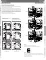
2-channel Broadcast Announcement
SYSTEM EXAMPLES
CONNECTIONS
Zone 2 speaker
BGM
Zone 2 speaker
(BGM cut)
Zone 3 speaker
BGM
Zone 3 speaker
(BGM cut)
Zone 1 speaker
BGM
Zone 2 speaker
Zone 3 speaker
WA-MA240N (240 W)
2-channel broadcast
announcement
Zone 1 speaker
2-channel
announcement
BGM
Zone 2 speaker
BGM
BGM
Zone 3 speaker
BGM
2-channel broadcast
announcement to
zone 1 only...
PREFACE
all-zone announcement between different work areas, and
other features provide outstanding system flexibility that
meets the needs of a wide range of applications, including
retail outlets, businesses, office buildings, factories, schools,
and more.
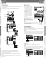
The term "Amplifier" in this manual refers to the Panasonic
WA-MA120N/240N Mixing Power Amplifier.
Amplifier
Line input
[LINE 1, 2]
Call microphone
Remote
Microphone
FEATURES
announcement priority levels (fixed). In case of an
emergency call or emergency announcement, lower
priority announcements are blocked automatically in
accordance with the priority levels.
• Easy switching of high impedance loudspeaker output
voltage between 100 V and 70 V for plenty of flexibility to
adapt to the needs of each system.
• Equipped with REC OUT, LINE OUT, INS IN/THRU/
OUT. The Amplifier can be expanded while connecting
equipment to enable announcements required for
operation of a particular business.
• External attenuators can be bypassed during all-zone
announcement. This allows emergency announcements,
even when an attenuator is being used in a local area.
• Operation on/off control can be use for remote switching
between operation and non-operation modes.
• Connecting a battery (24 V) allows continued operation in
case of a power outage.
INPUT 1
input terminal
[INPUT 1]
Remote
Microphone
input
[RM]
Built-in
power amplifier
1-channel
2-channel
CALL relay
Zone relay
Zone 2
output
terminal
[ZONE 2]
Zone 3
output
terminal
[ZONE 3]
Mixing
1-channel
2-channel
INPUT
D-OUT jack
[INPUT D-OUT]
Zone 1
output
terminal
[ZONE 1]
ZONE 1
CALL IN terminals
[ZONE 1 CALL IN]
Zone 1 speaker
Zone 2 speaker
Zone 3 speaker
External
power amplifier
Level
1
2
3
4
5
6
Zone 1 output audio signal source
All-zone announcement from emergency announcement equipment
All-zone announcement from telephone paging
All-zone announcement from INPUT 1 (during 1-channel announcement)
All-zone announcement from Remote Microphone
2-channel broadcast announcement from Remote Microphone
2-channel broadcast announcement from INPUT 1
Individual zone announcement from Remote Microphone
INPUT 2, 3, LINE 1,2
BLOCK DIAGRAMS
• Can be configured as a 1-channel or 2-channel
broadcast announcement system.
Supports
connection of up to four Remote
•
Microphones (WR-210AE). Individual zone, group, allzone, and 2-channel broadcast announcements are all
supported from Remote Microphones.
Expansion
to up to 30 zones is supported by
•
combining up to 10 Amplifier units.
• When multiple Amplifier units are used in combination,
all-zone announcement is supported even if each area
has a different system configuration.
Other
Functions
•
• Multiple inputs for two line inputs, three microphone/line
inputs, one Remote Microphone input, one telephone
paging input, and one EMG input. Supports connection to
business and emergency announcement equipment at a
single location.
• Announcement priority control with four 1-channel
Mixing
BGM player
PRODUCTS
PRODUCTS
1-channel announcement
Zone 1 speaker
Remote Microphone
announcement
BGM
CONNECTIONS
BLOCK DIAGRAMS
Mixing Power Amplifier
Announcement by
Remote Microphone
to zone 1 only...
Zone 1 speaker
SYSTEM EXAMPLES
44
• This Amplifier supports 2-channel broadcast announcement from INPUT 1 or a Remote Microphone.
• The illustration below shows the concept behind 2-channel broadcast announcement. This function can be used to announce
to zone 1 only, without interrupting the BGM being played in zones 2 and 3. Note, however, that zone1 2-channel broadcast
announcement is cancelled during all-zone announcement. Because of this, it coincides with the 1-channel announcement and
the output audio signal priority for zone 1 is shown in the table below.
WA-MA120N (120 W)
CONCEPT
CONCEPT
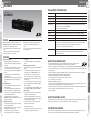
Mixing Power Amplifier
The WA-MA120N/240N is a Mixing Power Amplifier that
features multi-input, announcement priority control, call tone,
and other features.
You can select either a 120 W model (WA-MA120N) or 240
W model (WA-MA240N) to suit the structure of your system.
Features such as 2-channel announcement, Remote
Microphone announcement, zone expansion capabilities,
4
• When INPUT 1 and a Remote Microphone are both used for 2-channel broadcast announcement, the input is mixed.
45
PRODUCTS
4
PRODUCTS
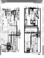
WA-MA120N/WA-MA240N
WA-MA120N/WA-MA240N
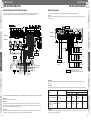
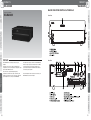
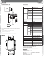
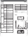
Front View
3
4
5
12
11
6
13
DIMENSIONS
CONCEPT
CONCEPT
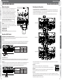
MAJOR OPERATING CONTROLS & TERMINALS
4
15
8
7
18
29
1
SYSTEM EXAMPLES
9
10
14
17
16
17
* The illustration shows the WA-MA120N. The WA-MA240N is the same in both appearance and function.
Rear View
19
29
25
26
27
28
30
38
37
39
40
CONNECTIONS
CONNECTIONS
365
SYSTEM EXAMPLES
2
41
420
46
22
Unit: mm
24
31
32
33
35
36
34
42
43
44
45
ACCESSORIES
Operating Instructions (this manual) ..........................1 pc.
Use the following items for installation work.
Power Cords (1.8 m)...................................................2 pcs. (1 flat 3-prong plug type, 1 round 2-prong plug type)
Spare Fuses................................................................1 pc. (For DC power output)
Rack Mounting Brackets.............................................2 pcs.
BLOCK DIAGRAMS
BLOCK DIAGRAMS
23
46
14
21
PRODUCTS
PRODUCTS
132
20
47
4
PRODUCTS
PRODUCTS
WA-MA120N/WA-MA240N
WA-MA120N/WA-MA240N
4
Model No.
Power Source
Power Consumption (AC)
Rated Output
Frequency Response
Distortion
Signal- to-Noise Ratio
Tone Control
Volume Control
Audio Signal Output
Power
Supply
Connector
TEL PAGING Audio Signal
Terminals
Control
(Telephone
Paging Input) Connector
EMG Terminals Audio Signal
(Emergency
Control
Equipment
Input)
Connector
INS IN Jack (Insertion Input)
ZONE 1 CALL IN
(for 2-channel Announcement)
ZONE 1-3,
Output Voltage/
DIRECT OUT Impedance
Terminals
Connector
755 W
0.5 A
4.5 A
8.5 A
10 A
20 A
120 W
240 W
50 Hz-15 kHz
Less than 1 % at 1 kHz rated output
More than 60 dB (-22 dBV input to ZONE output)
Bass:±10 dB at 100 Hz, Treble:±10 dB at 10 kHz
0 dB to -20 dB
0 dB to – ∞ (off)
MIC:–65 dBV/LINE:–22 dBV (selectable)
5 kΩ, electronically balanced, XLR-3-11 type connector
(female)
No-voltage make contact input, open voltage:+5 VDC,
short-circuit current:under 1 mA, Push-in terminal*3
–22 dBV, 10 kΩ, unbalanced, RCA pin jack x2 (monaural)
RM:–22 dBV/MIC:–65 dBV (selectable)
10 kΩ, electronically balanced
No-voltage make contact input, open voltage:+5 V DC, shortcircuit current:under 1 mA
1 CALL (2-channel announcement select)
2 BC (activation control of announcement)
3 ALL CALL (activation control of all-zone announcement)
4 Z1 (zone 1 select)
5 Z2 (zone 2 select)
6 Z3 (zone 3 select)
DC+24 V, MAX 200 mA
(Up to 4 Remote Microphones (WR-210AE) can be connected)
Push-in terminal*3
–22 dBV, 10 kΩ, electronically balanced
No-voltage make contact input, open voltage:+5 V DC,
short-circuit current:under 1 mA
Push-in terminal*3
0 dBV, 10 kΩ, electronically balanced
No-voltage make contact input, open voltage:+5 V DC,
short-circuit current:under 1 mA
Push-in terminal*3
0 dBV, 100 kΩ, unbalanced, RCA pin jack
100 V or 70 V balanced, M3 screw terminal*2
100 V/83 Ω
(changeable to 70 V/42 Ω)
M3 screw terminal*2
100 V/42 Ω
(changeable to 70 V/21 Ω)
Audio Signal In/Out
for expansion
INS OUT Jack
(Insertion Output)
INS THRU Jack
(Insertion Through Output)
INPUT D-OUT Jack
(Input Direct Output)
ALL CALL
Audio Signal
BUS
Control
IN/THRU
Connectors
Connector
CALL SIGN CNT Terminals
(Activation control of built-in call tones)
OPERATE ON/OFF Terminals
OPERATE LINK Terminal
ATT OVERRIDE Terminals
Announcement Priority Control (Input Priority at 1-Channel
Announcement)
Priority Indicator
PA OUTPUT LEVEL Meter
Other Functions
Phantom Power Supply for INPUT 1-3
Power Supply for External Equipment
Cooling Fan
Operating Temperature
Dimensions
Weight (Approx.)
Finish
Optional Products
WA-MA240N
0 dBV, 10 kΩ adapted, unbalanced, RCA pin jack
0 dBV, 10 kΩ adapted, unbalanced, RCA pin jack x2
(monaural)
0 dBV, 10 kΩ adapted, unbalanced, RCA pin jack
Through output from INS IN, unbalanced, RCA pin jack
0 dBV, 10 kΩ adapted, unbalanced, RCA pin jack
(Output for 2-channel announcement from INPUT 1 or RM)
–20 dBV balanced
Activation control of all-zone announcement
1 from EMG 2 from TEL/INPUT 1 3 from RM
9-pin female D-sub connector x2 (in/through)
No-voltage make contact input, open voltage:+5 V DC,
short-circuit current:under 1mA, Push-in terminal*3,
1:4-Tone (Up), 2:4-Tone (Down), 3:2-Tone (Down)
One-shot make:single playback, at make:repeat playback
No-voltage make contact input, open voltage:+5 V DC, shortcircuit current:under 1 mA, M3 screw terminal*2
Open collector output, withstand voltage:+30 V DC, operating
current:under 50 mA, M3 screw terminal*2
No-voltage make contact output (transfer type relay),
withstand voltage: 30 V DC, 250 V AC, contact current:under
3A (DC/AC), M3 screw terminal*2
Priority 1:EMG
Priority 2:TEL PAGING, INPUT 1
Priority 3:RM
Priority 4:INPUT 2,3, LINE 1,2
EMG, TEL, RM
5 points, -30/-20/-15/-8/0
• 2-channel announcement by Remote Microphone or paging microphone.
• Zone output extension by connecting plural units. (up to 30 zones by 10 units)
• All-zone announcement in various operating areas. (up to 10 areas)
+16 V, on/off selectable individually
DC+24 V, MAX 200 mA, M3 screw terminal*1
3 modes;Stop/Low speed/High speed
0 °C-+45 °C (32 °F -113 °F)
420 mm (W) x 146 mm (H) x 404 mm (D){13-17/32" (W) x 5-3/4" (H) x 15-29/32" (D)}
(Height includes rubber feet and depth includes projections such as rear protect cover.)
14 kg (30.87 lbs.)
15.5 kg (34.17 lbs.)
Panel:Gun Metallic painting (ABS Resin)
Case: black painting, Munsell N2.5 or equivalent (steel plate)
• Remote Microphone:WR-210AE
• Booster Power Amplifier:WA-BA240N (240 W)
0 dB = 1 V
*1 Barrier distance:8.12 mm, Suitable cable gauge:AWG18-14 (Solid)/AWG14 (Stranded)
*2 Barrier distance:6.27 mm, Suitable cable gauge:AWG22-14
*3 Suitable cable gauge:AWG22-14
* Dimensions and weight indicated are approximate.Specifications are subject to change without notice.
BLOCK DIAGRAMS
BLOCK DIAGRAMS
PRODUCTS
Control
(Only INPUT 1)
LINE 1,2 Jacks
RM Terminal Audio Signal
(Remote
Microphone Control
Input)
360 W
0.5 A
WA-MA120N
4Ω
M3 screw terminal*2
PRODUCTS
48
Audio Signal
225 W
SP4 Ω
Impedance
Terminal (Low Connector
Impedance
Loudspeaker
Output)
LINE OUT Jack
REC OUT Jack
CONNECTIONS
CONNECTIONS
Audio Signal Input
EMG
Others
INPUT 1-3
Connectors
125 W
Model No.
Audio Signal Output
SYSTEM EXAMPLES
SYSTEM EXAMPLES
Current Consumption (DC)
Non-operation mode
(standby)
Under normal operating
conditions according to
IEC60065
With rated output signal
Non-operation mode
(standby)
Under normal operating
conditions according to
IEC60065
With rated output signal
WA-MA120N
WA-MA240N
AC:110 V-120 V or 220 V-240 V (selectable), 50 Hz /60 Hz
DC:+24 V (Battery), M3 screw terminal *1
25 W
30 W
CONCEPT
CONCEPT
SPECIFICATIONS
49
4
PRODUCTS
PRODUCTS
WA-BA240N
WA-BA240N
MAJOR OPERATING CONTROLS & TERMINALS
WA-BA240N
CONNECTIONS
The WA-BA240N is a 240 W output monaural power
amplifier.
It includes 100 V and 70 V outputs for high-impedance
loudspeakers, as well as low-impedance loudspeaker output.
Inputs include LINE IN and 100 V.
Those who want to expand their high-impedance
loudspeakers but feel that the output of their main power
amplifier is insufficient can increase the output of their main
power amplifier to the 100 V input of the WA-BA240N.
Rear View
This will provide output up to 240 W from the WA-BA240N,
which is enough to support speaker expansion. In addition,
operation mode/non-operation mode switching can be
performed externally when the WA-BA240N at a distance
from the main power amplifier.
The term "Amplifier" in this manual refers to the Panasonic
WA-BA240N Booster Power Amplifier.
PRODUCTS
PRODUCTS
PREFACE
CONNECTIONS
BLOCK DIAGRAMS
BLOCK DIAGRAMS
SYSTEM EXAMPLES
SYSTEM EXAMPLES
Front View
CONCEPT
CONCEPT
Booster Power Amplifier
50
4
51
4
PRODUCTS
PRODUCTS
WA-BA240N
WA-BA240N
SPECIFICATIONS
ADJUSTING INPUT VOLUME
Power Source
CONCEPT
Power Amplifier
(WA-MA120N, MA240N, etc.)
for High-Impedance Loudspeakers
Power Consumption
(AC)
8A
LINE OUT
Line-level equipment, etc.
• When line-level equipment is connected to LINE IN, use the LEVEL knob on the back of the Amplifier to adjust the volume to
the desired level.
• Input volume cannot be adjusted when power amplifier output is connected to 100 V.
Adjust the output level of the power amplifier in this case.
Note:
• When LINE IN and 100 V are connected to different audio signal sources at the same time, the inputs are mixed.
365
29
PRODUCTS
DIMENSIONS
BLOCK DIAGRAMS
ACCESSORIES
420
14
132
Operating Instructions (this manual) ...........................1 pc.
Unit: mm
Use the following items for installation work.
Power Cords (1.8 m)...................................................2 pcs. (1 flat 3-prong plug type, 1 round 2-prong plug type)
Rack Mounting Brackets .............................................2 pcs.
Tip-Ring-sleeve (TRS) phone plug (gold plated) ........2 pcs.
BLOCK DIAGRAMS
0 dB = 1 V
*1 Barrier distance:8.12 mm,Suitable cable gauge:AWG18-14 (Solid) /AWG14 (Stranded)
*2 Barrier distance:6.27 mm,Suitable cable gauge:AWG22-14
* Dimensions and weight indicated are approximate.Specifications are subject to change without notice.
PRODUCTS
20 A
240 W
50 Hz - 15 kHz
Less than 1 % at 1 kHz rated output
More than 80 dB
LINE IN
0 dB to – ∞ (off)
LINE IN Jack
0 dBV, 100 kΩ electronically balanced, Tip-Ring-Sleeve(TRS) phone jack
100 V Terminal
100 V, transformer balanced, M3 screw terminal *1
Audio signal Output
LINE THRU Jack
Through output from LINE input, balanced, Tip-Ring-Sleeve (TRS) phone jack
SP100 V
Output Voltage 100 V/42 Ω
Terminal
/Impedance
Connector
M3 screw terminal *2
SP70 V
Output Voltage 70 V/21 Ω
Terminal
/Impedance
Connector
M3 screw terminal *2
SP4 Ω Terminal Impedance
4Ω
(Low Impedance Connector
M3 screw terminal *2
Loudspeaker
Output)
OPERATE ON/OFF Terminals
No-voltage make contact input, open voltage:+5 V DC,
short-circuit current:under 1 mA, M3 screw terminal *2
OPERATE LINK Terminal
Open collector output, withstand voltage:+30 V DC,
operating current:under 50 mA, M3 screw terminal *2
PA OUTPUT LEVEL Meter
5 points, –30/–20/–15/–8/0
Cooling Fan
3 modes;Stop/Low speed/High speed
Operating Temperature
0 °C - +45 °C (32 °F - 113 °F)
Dimensions
420 mm (W) x 146 mm (H) x 404 mm (D){16-17/32" (W) x 5-3/4"(H) x 15-29/32" (D)}
(Height includes rubber feet and depth includes projections such as rear protect cover.)
Weight (Approx.)
15 kg (33.1 lbs)
Finish
Panel: Gun Metallic painting (ABS Resin)
Case:brack painting, Munsell N2.5 or equivalent (steel plate)
CONNECTIONS
CONNECTIONS
730 W
0.1 A
Rated Output
Frequency Response
Distortion
Signal- to-Noise Ratio
Volume Control
Audio signal Input
LEVEL Knob
52
190 W
SYSTEM EXAMPLES
SYSTEM EXAMPLES
Current Consumption (DC)
Non-operation mode
(standby)
Under normal operating
conditions according to
IEC60065
With rated output signal
Non-operation mode
(standby)
Under normal operating
conditions according to
IEC60065
With rated output signal
AC:110 V - 120 V or 220 V - 240 V (selectable), 50 Hz /60 Hz
DC:+24 V (Battery), M3 screw terminal *1
14 W
CONCEPT
100 V OUT
Pre-amplifier, etc
4
53
4
PRODUCTS
PRODUCTS
WU-ZM001E
WU-ZM001E
EXPLANATION OF TERMINOLOGY
SYSTEM EXAMPLES
CONNECTIONS
Amplifier
This refers to the mixing power amplifier WA-MA120N/240N.
Emergency message
Special messages announced during emergency situations. There are two messages, EMG1 and EMG2.
EMG1/EMG2
Messages announced in an event of emergency. EMG2 has a priority over EMG1.
Voice message
Message announced in an event of emergency. Please register the message that is to be played
in an event of emergency as VOICE MESSAGE.
e.g. Fire! Evacuate the building quickly!
Signal
The alarm given before voice message to arouse attention.
Message
Audio messages announced during normal operations. There are two types, MSG and MSGS.
MSG
These messages are created from one sound file. A maximum of 100 MSG can be used.
MSGS
These messages are created from multiple MSG messages. A maximum of 50 MSGS can be used.
Announcement
The back ground music can be interrupted and announcements, such as chimes or other messages,
can be made. If an announcement is played back while a different announcement is being played
back, the announcement that is made second is played back. All of the messages
recorded on the sound message unit are announcements.
BGM
BGM is Back Ground Music (it is a message). If an announcement is made while BGM is playing,
the BGM is stopped and the announcement is played back. The BGM starts again when the
announcement is finished.
FEATURES
• Making announcements
each pattern.
• You can quickly change the schedule by switching the
patterns.
Making
emergency announcements
•
• There are two types of emergency messages; EMG1 and
EMG 2.
• You can write voice message up to 20 seconds on the
internal memory for each EMG1 and EMG2. You can
also write a signal up to 10 seconds on the internal
memory as a lead for the voice message. Emergency
message can be made even if the SD memory card has
been removed.
• You can make emergency announcements by touching
just one switch. EMG 1 switch is for EMG 1 and EMG 2
switch is for EMG 2.
• You can from the mixing power amplifier’s EMG1 Control
Input (for EMG1) and EMG2 Control Input (for EMG2).
Support
software
•
• Support software is provided so you can easily create a
schedule on your personal computer *2.
• Download the schedule data that you create to the SD
memory card and just plug it into the sound message unit
to make scheduled announcements.
• This software can also be used to modify the system
settings and to manage messages.
*1 MP3 is MPEG1 Audio Layer III.
*2 Supports Windows 2000 and Windows XP (Home/Professional).
(Languages include English and Simplified Chinese.)
ABOUT THE SD MEMORY CARD
• Be sure to format the SD memory card on this Sound Message Unit before using it. (However, the SD
memory card provided was formatted at the factory and does not need to be formatted).
• SD memory cards formatted on a different machine or a personal computer (Windows standard formatting function) cannot be
used on this unit. Problems may occur preventing normal recording and playing back from these cards. If this happens, format
the card on this unit.
• SD memory cards with the following capacity (8 MB to 2 GB) can be used on this unit. (Panasonic cards are recommended.)
8 MB, 16 MB, 32 MB, 64 MB, 128 MB, 256 MB, 512 MB, 1 GB and 2 GB
• The actual available capacity of the SD card is less than that indicated.
• An SD card other than the recommended one may not work well in this unit.
• Do not use mini SD card or micro SD card.
• Multi Media Cards (MMC) cannot be used.
• If the access lamp is lit or flashing that means that data is being written to or from the card. If the Amplifier is turned off or the
SD memory card is removed it may malfunction or the data on the card may be lost.
• The data on the SD memory card may be lost or damaged due to electric interference, static electricity or a malfunction of this
unit or the card. Be sure to back up any important data to your personal computer.
• SD logo is a trademark.
ABOUT THE INTERNAL CLOCK
The Sound Message Unit’s internal clock has a back up battery that operates for three months after the AC power is turned off.
However, the AC power needs to be hooked up for a minimum of 1.5-2 days to charge the battery.
COPYRIGHT EXPLANATION
Permission from the copyright holder may be necessary for some songs available on the market, depending on the song, the
reason it is used and the format in which it is used. Relevant laws should be followed in these situations.
BLOCK DIAGRAMS
• Depending on different usage, announcement and
emergency announcement could be easily played back
as messages.
• You can make announcements that have been recorded
on the sound message unit or a personal computer.
• You can assign any message to the three MESSAGE 1-3
switches.
• You can playback not only file in WAV format but also
that in MP3 *1 format.
• You can make announcements that have been previously
set from the MSG Control Input on the mixing power
amplifier.
• Recording messages
• You can record messages to the SD memory card from
the REC IN terminal.
• You can switch the REC IN terminal sound source from
“Mic” to “Line” depending on the equipment connected.
• You can listen to the recorded messages on headphones
hooked up to the PHONES terminal.
• Recorded audio signals can be assigned to the
MESSAGE 1-3 switches and the MSG Control Input, and
played as announcements.
• Scheduled announcements
• You can playback messages according to the schedule,
which is configured in advance.
• Schedules (patterns) can be set in units of one day and
the patterns can be assigned to a day.
• You can make up to nine types of patterns and
announcements with 999 steps can be registered for
PRODUCTS
PRODUCTS
• Emergency messages that have been registered to the
internal memory can be played back at the touch of a
button.
• It is easy to create schedules with the support software (for
personal computers).
Explanation
CONNECTIONS
BLOCK DIAGRAMS
PREFACE
Name
SYSTEM EXAMPLES
54
WU-ZM001E
CONCEPT
CONCEPT
Sound Message Unit
This Sound Message Unit is intended for installation on the
WA-MA120N/240N mixing power amplifier (sold separately).
• It makes it easier to playback chimes or make
announcements that have been recorded to SD memory
cards.
• The built-in program timer function makes it possible to
make announcements on a set schedule.
4
55
PRODUCTS
WU-ZM001E
WU-ZM001E
MAJOR OPERATING CONTROLS & TERMINALS
RECORDING METHODS
Front View
Notes on recording
• Sound data is recorded to the SD memory card. Do not remove the SD memory card during recording.
• You can switch the time display between elapsed recorded time and remaining recording time by pressing the SCHEDULE
switch while recording.
4
CONCEPT
CONCEPT
4
PRODUCTS
Press the SCHEDULE switch
Press the SCHEDULE switch
Remaining recording time
Note:
The elapsed/remaining time displayed during recording is not exact. There might be some difference between the displayed time and the actual one.
• The recorded sound data file is saved to the "ZM001" folder on the SD memory card.
* Folders are generated automatically when the SD memory card is formatted.
SD memory card
PRIVATE
SYSTEM EXAMPLES
SYSTEM EXAMPLES
Elapsed recorded time
MEIGROUP
ZM001
Recording formats
The following sound data formats can be recorded to this Sound Message Unit.
Item
Description
File format
Linear PCM (WAV)
Audio sample rate
44.1 kHz
Audio sample size
16 Bit
Stereo/Mono
Mono
Connecting external equipment
External equipment is connected as shown below.
• Connecting to REC IN
Connect the external equipment's audio signal out or microphone to this jack. Set the audio signal level (LINE/MIC) to match the
device that you are connecting.
MESSAGE
SELECT
• Connecting to PHONES
SCHEDULE
RESET
Note:
REC IN terminal of this unit is for unbalanced
input. The audio message could not be recorded
if the input is balanced. Please use microphones
or equipment of unbalanced output.
2
MENU
Headphone
CANCEL
1
REC IN
2
PHONES
OUTPUT
CLK ADJ.
SD CARD
Microphone,etc.
ENTER
EMG
3
WU-ZM001
BLOCK DIAGRAMS
BLOCK DIAGRAMS
Connect headphones to this jack.
56
1
PRODUCTS
PRODUCTS
Rear View
CONNECTIONS
CONNECTIONS
PSS
57
4
PRODUCTS
PRODUCTS
WU-ZM001E
WU-ZM001E
SOUND MESSAGE UNIT SUPPORT SOFTWARE
• Use the SELECT dial to move between
screens on the same level.
Normal operation
• Use the ENTER switch and the CANCEL
switch to move between different levels.
Use MENU switch to go to setting screen
Time setting screen
CONCEPT
CONCEPT
CONFIGURATION OF MENU SCREEN
4
Time display setting screen
Recording screen
Message recording screen
Emergency message recording screen
Monitoring screen
Schedule setting screen
Schedule pattern creation screen
Weekly schedule setting screen
SYSTEM EXAMPLES
SYSTEM EXAMPLES
Internal clock setting screen
Schedule file selection screen
MSGS creation screen
Message repetition setting screen
Message type setting screen
Message switch setting screen
CONNECTIONS
CONNECTIONS
Message setting screen
MSGCONT setting screen
Message name setting screen
Data cheak screen
Emergency message setting screen
VOLUME screen
CONTROL AMP setting screen
SPEAKER CHECK setting screen
SD memory card screen
System file screen
Emergency message screen
Sound file clean up screen
SD memory card format screen
BLOCK DIAGRAMS
BLOCK DIAGRAMS
System screen
58
PLAY INTERVAL setting screen
PRODUCTS
PRODUCTS
Message delete screen
59
4
PRODUCTS
PRODUCTS
WU-ZM001E
4
WU-ZM001E
SPECIFICATIONS
206 mm (W) x 45 mm (H) x 124 mm (D)
* Excluding protrusions.
Weight (Approx.)
665 g
Finish
Panel: Gun metal coating
Output level: -12 dBV, output level is adjustable
Output impedance: 32 Ω unbalanced (load impedance:
32 Ω or higher)
S/N quotient: 70 dB or higher
Stereo: 3.5f mini-jack
EMG1 message execute
input [EMG1]
Open circuit voltage 5 V; Short circuit current 1 mA
(on back of Amplifier)
EMG2 message execute
input [EMG2]
Open circuit voltage 5 V; Short circuit current 1 mA
(on back of Amplifier)
Regular announcement
execute input [MSG]
Open circuit voltage 5 V; Short circuit current 1 mA
(on back of Amplifier)
Clock compensation input
[CLK ADJ.]
Open circuit voltage 5 V; Short circuit current 1 mA
(on back of Amplifier)
Emergency message
EMG 1-2 switches [EMG1] and [EMG2]
Regular announcements
MESSAGE 1-3 switches [MESSAGE1-3]
Menu controls
LCD: 16 characters x 2 lines
MENU switch [MENU], ENTER switch, CANCEL switch [CANCEL],
SELECT dial [SELECT], SCHEDULE switch [SCHEDULE], CLK ADJ
switch [CLK ADJ.]
Volume adjustment
REC IN knob [REC IN]
PHONES knob [PHONES]
OUTPUT knob [OUTPUT]
ACCESSORIES
Use the following items for installation work.
Internal Connection Cables..........................................2 pcs.
Screws (M3 x 6) ...........................................................2 pcs.
Operating Instructions (this manual) ..............................1 pc.
Support software (CD-ROM)..........................................1 pc.
SD memory card (64 MB) .............................................1 pc.
DIMENSIONS
SD memory card (Panasonic cards are recommended)
*Up to a maximum of 2 GB
Recording
WAV format: 44.1 kHz, 16 bit, MONO
* Maximum continuous recording time is 10 minutes.
Schedule pattern assigned to day of the week
9 types of schedule patterns
999 steps possible for each pattern
100 types of messages or combined messages can be
set for each step
Emergency message
2 types of messages, EMG1 message and EMG2 message can be
written to the internal memory
Each message has a signal tone (10 seconds) and a message
(20 seconds)
MESSAGE
SELECT
1
SCHEDULE
RESET
2
MENU
CANCEL
1
REC IN
2
PHONES
OUTPUT
CLK ADJ.
SD CARD
194
206
ENTER
EMG
3
WU-ZM001
Unit: mm
BLOCK DIAGRAMS
Scheduled announcements
7.5
WAV format: 44.1 kHz, 16 bit, MONO
MP3 format: 44.1 kHz, 128 kbps, STEREO
* STEREO audio signals are played back mixed on both
channels.
124
Playback
4
PRODUCTS
Dimensions
Input level: Microphone -65 dBV/Line -12 dBV alternating,
input level is adjustable
Input impedance: 10 KΩ unbalanced
S/N quotient: 70 dB or higher (Line)
Monaural: 3.5 f mini-jack
22.5
SYSTEM EXAMPLES
CONNECTIONS
Recording input
PRODUCTS
BLOCK DIAGRAMS
0 C˚ to +45 C˚
CONNECTIONS
60
Operating temperature range
1 % or less (1 kHz standard)
Microphone system
Storage media
Audio signal format
The margin of the monthly error:±30 seconds (25˚C)
Line system
SYSTEM EXAMPLES
Controls
Accuracy of the internal clock
100 Hz to 10 kHz ± 2 dB
Approximately 220 mA
Monitor output
MSG Control Input/Output
50 Hz to 15 kHz ± 2 dB
Consumption Current
Distortion factor
Audio signal input and
output
Computer software provided
(compatible with Windows 2000 and XP)
Supported languages: English and Simplified Chinese
24 V DC (supplied internally by amplifier)
45
Frequency characteristics
Support software
Rated Voltage
CONCEPT
CONCEPT
Power Requirements
61
4
PRODUCTS
PRODUCTS
WU-ZS001E
WU-ZS001E
MAJOR OPERATING CONTROLS & TERMINALS
SYSTEM EXAMPLES
1 CN101 Terminal
2 CN102 Terminal
3 CN103 Terminal
4 CN104 Terminal
5 DIP Switches
PREFACE
This Surveillance Unit is intended for installation on the WAMA120N/240N Mixing Power Amplifier (sold separately).
Installation of the Surveillance Unit ensures system reliability
and safety by detection of speaker line failures, as well as
audio signal problems and abnormally high temperatures in
the amplifier.
• Detects and notifies speaker line faults (shorts,
disconnections, grounding), amplifier audio signal
problems, and abnormally high amplifier temperatures.
• A built-in interval timer schedules automatic checks for
speaker line failures at a preset interval.
• Non-stop monitoring for amplifier audio signal problems and
FEATURES
• Speaker Line Check
Check
(n-1) Fault
Check Time
(n)
• Audio output of the amplifier is constantly monitored to
ensure operation is normal.
• Indicators on the front panel of the mixing power amplifier
signal problems. Notification of the problem is also sent from
the SURVEILLANCE I/F connector at the same time.
• Detection of Abnormally High Amplifier Temperature
• The amplifier is constantly monitored to ensure normal
temperature increase.
• Indicators on the front panel of the mixing power amplifier
signal abnormalities. Notification of the abnormality is also
sent from the SURVEILLANCE I/F connector at the same
time.
Fixed settings
TIMER1
TIMER2
MASTER/SLAVE
POWER ON CHECK
BUS SYNC ENABLE
Description
Settings
Factory
Default
Fixed at factory default setting
–
ON
Interval timer setting 1
None/10 minutes/ 24 hours
Interval timer setting 2
60minutes/24 hours
Master/slave setting
MASTER/SLAVE MASTER
Power on speaker line check setting ON/OFF
ON
Speaker line test sync on/off for ON/OFF
OFF
multi-amp connection
6 SURVEILLANCE I/F Connector
Pin Number
1
2
3
4
5
6
7
8
9
10
11
12
13
14
• Detection of Amplifier Audio Signal Problems
Name
15
16
17
18
19
20
21
22
23
24
25
Signal Name
IN/OUT Signal/Logic
Required Action
ZONE1 SHORT
OUT Active Low Zone 1 speaker line is shorted.
ZONE1 OPEN
OUT Active Low Zone 1 speaker line is disconnected.
ZONE2 SHORT
OUT Active Low Zone 2 speaker line is shorted.
ZONE2 OPEN
OUT Active Low Zone 2 speaker line is disconnected.
ZONE3 SHORT
OUT Active Low Zone 3 speaker line is shorted.
ZONE3 OPEN
OUT Active Low Zone 3 speaker line is disconnected.
Reserved
Reserved
Reserved
Reserved
GROUND FAULT
OUT Active Low Some speaker lines are grounded.
PA SIGNAL FAULT OUT Active Low Power amplifier audio signal is faulty.
CHECKING/SETTING OUT Active Low During measurement of the speaker line reference
BUSY
impedance or during check of the speaker lines.
REFERENCE ERROR OUT Active Low The speaker line reference impedance couldn’t
be measured successfully.
GND
GND
GND
PA TEMP FAULT
OUT Active Low Power amplifier temperature is faulty.
COMM FAULT
OUT Active Low Serial Communication is faulty.
Reserved
Reserved
Reserved
GND
GND
CLOCK ADJ CONT
IN
One-shot make Adjust control of Interval clock
SP LINE REFERENCE
IN
One-shot make Measurement of the speaker line reference
SETTING ACTIVATION
impedance (Initial setting) starts.
One-shot make Check of the speaker line impedance starts.
SP LINE CHECK
IN
ACTIVATION
GND
GND
GND
BLOCK DIAGRAMS
• Check interval can be set to none, 10 minutes, 60 minutes,
or 24 hours. The factory default setting is 24 hours.
• Execution of speaker line failure detection cancelled during
all-zone announcement.
And it will not be resumed automatically when all-zone
announcement ends.
• Indicators on the front panel of the mixing power amplifier
signal malfunction. Notification of the fault is also sent from
the SURVEILLANCE I/F connector at the same time.
Detection of a short in a speaker line causes automatic cut
off of the line's output.
• CHECK/SETTING switch can be used to execute the
speaker line check or to set the line impedance reference
value. The same setting is also possible from the
SURVEILLANCE I/F connector.
• The Surveillance Unit's indicator and the FAULT indicator on
the front of the mixing power amplifier flash to indicate that
speaker line failure detection is in progress and while the line
impedance reference value is being obtained.
• Detection of a short causes the applicable line to be cut.
• The speaker line check will not be performed during all-zone
announcement.
And when there is no all-zone announcement, it will be
performed as scheduled by the time interval setting.
DIP Switch
Number
1
2
3
4
5
6
PRODUCTS
• Speaker lines can be checked individually for shorts and
disconnections.
• Overall speaker line check for grounding.
• Speaker line check is performed according to the time
interval setting.
Notification about any faults occurred during the time interval
will not be made at once. See the illustration below for
details.
Next fault detection and notification
Time interval
BLOCK DIAGRAMS
abnormally high temperatures, and notifies when
abnormalities are discovered.
• Speaker line failure detection can be executed by Sound
Message Unit scheduler.
• Switch operation allows manual execution of speaker line
check.
• SURVEILLANCE I/F connector supports execution of
speaker line check and acquisition of each fault notification.
• Fault notification from the SURVEILLANCE I/F connector
allows configuration of a system that switches to a backup
amplifier when the power amplifier has a problem.
CONNECTIONS
CONNECTIONS
Top of Unit
SYSTEM EXAMPLES
PRODUCTS
WU-ZS001E
CONCEPT
CONCEPT
Surveillance Unit
62
4
63
4
PRODUCTS
PRODUCTS
WU-ZS001E
WU-ZS001E
Pin Number
Front of Unit
SURVEILLANCE I/F
SP LINE
SETTING
STATUS
5
AMBER-NO SETTING
GREEN-SETTING COMPLETED
RM DC
/DC OUT
T1AL
13
25
VOLTAGE
SELECTOR
4
ZONE
3
2
1
GROUND
FAULT
RED-SHORT
AMBER-OPEN
AC IN
POWER
1
SIGNAL
GND
ZONE1 SHORT
Zone 1 short
Check for short in wiring of Zone 1.
2
ZONE1 OPEN
Zone 1 disconnection
Check for disconnection in wiring of Zone 1.
3
ZONE2 SHORT
Zone 2 short
Check for short in wiring of Zone 2.
4
ZONE2 OPEN
Zone 2 disconnection
Check for disconnection in wiring of Zone 2.
5
ZONE3 SHORT
Zone 3 short
Check for short in wiring of Zone 3.
6
ZONE3 OPEN
Zone 3 disconnection
Check for disconnection in wiring of Zone 3.
7
Reserved
8
Reserved
9
Reserved
10
Reserved
11
GROUND FAULT
Zone grounding
Grounding
12
PA SIGNAL FAULT
Power amplifier audio
Check the amplifier’s power amplifier circuit.
fault
14
14
1 SURVEILLANCE I/F Connector
2 CHECK/SETTING Switch
3 SETTING STATUS Indicator
4 SP LINE FAULT ZONE 1-5 Indicators
5 SP LINE FAULT GROUND FAULT Indicator
3
4
BUSY
progress
REFERENCE ERROR
Speaker line reference
There is a short or ground fault in one of the
value error
speaker lines. Identify the line in accordance with
for location of the short in the applicable line.
Meaning
Reference value not set or abnormal
Reference value setting operation in progress
Speaker line check enabled (reference value set correctly)
Speaker line check in progress
Speaker line is shorted (SHORT)
Speaker line is disconnected (OPEN)
No speaker line short or disconnection
Speaker line is grounded fault
No speaker line grounding fault
15
GND
GND
GND
16
PA TEMP FAULT
Power amplifier high
Check for a faulty fan, and check amplifier’s
temperature fault
power amplifier circuit.
Communication error
Check the amplifier’s internal wiring. Also
notification
check the Sound Message Unit for faults.
GND
17
COMM FAULT
18
Reserved
19
Reserved
20
Reserved
21
GND
GND
22
CLOCK ADJ CONT
Clock adjustment input
23
SP LINE REFERENCE
SP line reference
SETTING ACTIVATION
setting activation
SP LINE CHECK
SP line check
ACTIVATION
activation
GND
GND
25
GND
BLOCK DIAGRAMS
BLOCK DIAGRAMS
Speaker line check in
the indicators or SURVEIL LANCE I/F, and check
24
64
CHECKING/SETTING
PRODUCTS
5
Indicator Condition
Colour
Status
Amber
Lit
Amber
Flashing
Green
Lit
Green
Flashing
Red
Lit
Amber
Lit
–
Unlit
Red
Lit
–
Unlit
Required Action
1
13
Code
Meaning
CONNECTIONS
CONNECTIONS
SP LINE FAULT
Signal Name
SYSTEM EXAMPLES
SYSTEM EXAMPLES
CHECK
/SETTING
PRODUCTS
SURVEILLANCE I/F Connector Signals
CONCEPT
CONCEPT
MAJOR OPERATING CONTROLS & TERMINALS
4
65
4
PRODUCTS
PRODUCTS
WU-ZS001E
WU-ZS001E
SPECIFICATIONS
Power
Rated Voltage
24 V DC (supplied internally by amplifier)
Requirements
Consumption Current
Approximately 100 mA
Fault Detection
Line
Short (When impedance is -50 % of reference impedance value)
Disconnect (When impedance is +50 % of reference impedance value)
8
Grounding (When ground impedance value is 50 kΩ or less)
Amplifier
CONCEPT
CONCEPT
Front of Mixing Power Amplifier
4
Audio fault (When audio that is greater than the pilot signal level cannot
be detected by the amplifier circuit.)
Abnormally high temperature (When transformer temperature is +100 ˚C
Indicator
Speaker line check trigger/Impedance reference value acquisition trigger
LED
Impedance reference value setting/Speaker line check status indicator
Operation
6 FAULT Indicator [FAULT]
When this Surveillance Unit is installed, this indicator lights upon detection of a fault.
• Speaker system abnormality (short, grounding, disconnection)
• Power amplifier fault (voice system fault, abnormally high temperature)
Flashes when checking or acquiring reference value for speaker line.
(amber/green)
Line short/disconnect indicator: ZONE 1-3 (red/amber)
GROUND FAULT indicator (red)
Other I/F
SW
Line check trigger/Impedance reference value acquisition trigger
Parallel
External I/F
Input 2 (Tr input): Open circuit voltage 5 V; Short circuit current 1 mA
SYSTEM EXAMPLES
SYSTEM EXAMPLES
or greater)
SW
Output 17 (open collector output): No-voltage make contact, control
1 second
Time Adjustment
Go out
Light
Go out
Light
Light
Go out
FAULT Indicator flashes once a second upon detection of
short circuit or open circuit.
150 mm (W) x 18 mm (H) x 88 mm (D)
Weight (Approx.)
80 g
Ambient Temperature
0 ˚C to +40 ˚C
DIMENSIONS
FAULT Indicator flashes twice a second if the reference
impedance value of the speaker line is not set or is faulty.
In this case, set the reference value before performing
speaker line check.
FAULT Indicator lights if there is any abnormally high
temperature in Power Amplifier or any audio signal problems.
Light
Go out
Input (Tr input): Open circuit voltage 5 V; Short circuit current 1 mA
Dimensions
PRODUCTS
PRODUCTS
Go out
FAULT Indicator flashes 5 times every second during speaker
line check or reference impedance value setting.
FAULT Indicator does not light if there is not any abnormality.
80
Light
CONNECTIONS
CONNECTIONS
voltage 30 V max., control current 50 mV max. Connector: D-sub 25-pin
8
ZONE LED of each zone light during reference value setting or speaker line check. And then they go out one after another in the order
of ZONE number (from ZONE 1 to ZONE 3).
(B) Fault Indicator [FAULT]
FAULT Indicator on the front of the Amplifier flashes quickly during reference value setting or speaker line check.
(C) SETTING STATUS Indicator [SETTING STATUS]
Unit: mm
3
This indicator flashes amber during reference value setting and flashes green during speaker line check .
66
15
150
BLOCK DIAGRAMS
BLOCK DIAGRAMS
(A) ZONE LED [ZONE1/ZONE2/ ZONE3]
67
4
PRODUCTS
PRODUCTS
WR-210AE
WR-210AE
MAJOR OPERATING CONTROLS & TERMINALS
Remote Control Microphone
WR-210AE
SYSTEM EXAMPLES
SYSTEM EXAMPLES
Front View
CONCEPT
CONCEPT
4
PRODUCTS
This Remote Microphone is designed for use with public
address (PA) systems. It supports both separate zone
announcement and all-zone announcement capabilities.
• Connecting an recording device to the Remote
Microphone's REC OUT terminal makes it possible to
record messages from the microphone.
• The MIC button and LINE button allow you to select MIC
audio or LINE audio for announcements.
• PA system built-in call signs can be sounded using the
Remote Microphone's CALL SIGN button.
• The priority function allows you to set the order of priority
between Remote Microphones if more than one Remote
Microphone is connected.
• The BUSY indicator shows the current busy status of the
Remote Microphone.
Bottom View
BLOCK DIAGRAMS
BLOCK DIAGRAMS
PREFACE
PRODUCTS
68
CONNECTIONS
CONNECTIONS
Rear View
69
4
PRODUCTS
PRODUCTS
WR-210AE
SPECIFICATIONS
4
MEMO
Power Supply
Ambient Temperature
Dimensions
CONCEPT
CONCEPT
General
24 V DC, 45 mA or less (connection terminal)
0 °C - +45 °C
250 (W) mm x 55 (H) mm x 155 (D) mm (excluding projections and flexible
microphone)
Approx. 740 g {1.63 lbs}
Top case:
OA ivory color (Munsell value 5.5Y7.5/0.3 approximate color)
Bottom case: Gray color (Munsell value N5.5 approximate color)
Weight
Finishing
Frequency Characteristic
Distortion
Microphone Input
SN Ratio
LINE IN
SN Ratio
Audio Output
CONNECTIONS
CONNECTIONS
Record Output
Line: 50 Hz-15 000 Hz -3±2 dB
1 % or less (at 1 000 Hz)
Unidirectional ECM microphone length: 350 mm
Input Sensitivity: -49 dBV (-44 dBV at factory)
50 dB minimum
ø 6.3 mm tip sleeve phone jack unbalanced
Input Sensitivity: -12 dBV (-2 dBV at factory)
Input impedance 10 kΩ
70 dB minimum
Connection terminal H,C, COM (0 V) balance
Output Level:0 dBV, matching load impedance 600 Ω
ø 6.3 mm tip sleeve phone jack unbalanced
Output Level:0 dBV, matching load impedance 10 kΩ
SYSTEM EXAMPLES
SYSTEM EXAMPLES
Audio-signal Input/Output
Control Output (Quick connection terminal panel)
Control Capacity
Announcement Control
Zone Control
All-Zone Control
Call Sign Control
Priority Control
Max: 30 V DC, 80 mA DC
1 channel
1-10 channel
CK0 one channel
Rising, falling, 1 channel each
Priority input, priority output 1 channel each
Operation Buttons
Indicators
Extension I/F Connector
Individual, microphone, channel, all-zone, call sign up/down, announce
OPERATE, ON AIR, BUSY
1
DIMENSIONS
250
(5)
50
155
360
50
46
(5)
BLOCK DIAGRAMS
BLOCK DIAGRAMS
PRODUCTS
PRODUCTS
Other
Unit: mm
70
71
4
PRODUCTS
PRODUCTS
WR-201E
WR-201E
SPECIFICATIONS
Remote Microphone
General
WR-201E
Power Supply
Ambient Temperature
Dimensions
Weight
Finishing
CONCEPT
CONCEPT
4
24 V DC, 45 mA or less (connection terminal)
0 °C - +45 °C
107 mm (W) x 55 mm (H) x 155 mm (D) (excluding projections and flexible microphone)
Approx. 400 g {0.88 lbs}
Top case: OA ivory color (Munsell value 5.5Y7.5/0.3 approximate colour)
Bottom case: Gray color (Munsell value N5.5 approximate colour)
Audio-signal Input/Output
SYSTEM EXAMPLES
SN Ratio
LINE IN
SN Ratio
Audio Output
CALL SIGN
This single-channel Remote Microphone is designed for use with public address (PA) systems.
• A LINE IN terminal is available to connect an external sound source such as a CD player or background music (BGM) device.
• The CALL SIGN button on the Remote Microphone can be used to play the call signs that are on the PA system.
MAJOR OPERATING CONTROLS & TERMINALS
Front View
Rear Panel
Control Output
Announcement Control
Call Sign Control
1 channel
1 channel
CONNECTIONS
CONNECTIONS
PREFACE
Line: 50 Hz-15 000 Hz -3 dBV±2 dBV
1 % or less (at 1 000 Hz)
Unidirectional ECM microphone length: 350 mm
Input Sensitivity: -49 dBV (-44 dBV at factory)
50 dB minimum
ø3.5 mm stereo mini phone jack
Input Sensitivity: -12 dBV (-2 dBV at factory)
Input impedance 10 kΩ
70 dB minimum
Connection terminal H,C, 0 V balance
Output Level:0 dBV, matching load impedance 600 Ω
2 falling tones
SYSTEM EXAMPLES
Frequency Characteristic
Distortion
Microphone Input
Max: 30 V DC, 160 mA DC (rating of contacts )
Max: 30 V DC, 80 mA DC (rating of contacts )
Other
Bottom View
Operation Buttons
Indicators
microphone, LINE, call sign
OPERATE, ON AIR
DIMENSIONS
50
(5)
PRODUCTS
Panasonic
50
46
72
(5)
BLOCK DIAGRAMS
BLOCK DIAGRAMS
155
360
PRODUCTS
107
Unit: mm
73
EMG
CONT
TEL
CONT
G
+
G
+
G
+
CLK +
ADJ. G
EMG 2
EMG 1
MSG
Z3
Z2
Z1
G
DC+24V
RM
CONT ALL CALL
BC
CALL
-22dBV(RM)/ G
-65dBV(MIC)
10kohm BAL
C
H
G
+
-22dBV
G
10kohm BAL
C
H
G
+
0dBV
C
10kohm G
BAL
H
RM
TEL
HA
HA
(REAR)
RM/MIC
(REAR)
RM
(REAR)
TEL PAGING
BLOCK DIAGRAMS
OPTION
VCC24V(F)
INV
INPUT D-OUT
Power
Mute
EMG
CONT
1
H
Priority Control
ALL CALL BUS THRU
ZONE SEL SW
BA
BA
0dBV
10kohm
UNBAL
SIGNAL
ALL CALL BUS IN
RM
TEL/
CONT INPUT 1
CONT
10
2
UNITS SET
(REAR)
C
ALL CALL CONT
3
2
ZONE SEL Control
+16V
VCC 18V
VCC 5V
DC24V
VCC24V
for
PA BLOCK
Reg.
+VL
+VH
OPERATE
CONT
DC24V
EMG OPERATE ON CONT
ZONE 1 ZONE 2 ZONE 3
ON
ON
ON
Control
PA
OPERATE
CALL SEL
OT
FUSE
Power
Mute
VOLTAGE
SELECTOR
ZONE SEL
FUSE
OUT
IN B
FUSE
FUSE
FUSE
PT
VCC24V(F)
FUSE
(REAR)
POWER
ZONE 1
CALL IN
ZONE 3
ZONE 2
AC
110-120V/
220-240V
+
- DC +24V OUT
+
- DC +24V IN
G
G
OPERATE LINK CONT
G
OPERATE OFF CONT
OPERATE ON CONT
H
C
C
H
C
H
ZONE 1
ATT OVERRIDE
DIRECT OUT
K2(C)
K1(H)
IN A
C
H
SP0V
SP70V
SP4ohm
SP100V
FAN
INS THRU
0dBV
100kohm
UNBAL
INS IN
0dBV
10kohm
UNBAL
INS OUT
0dBV
10kohm
UNBAL
LINE OUT
0dBV
10kohm
UNBAL
REC OUT
WA-MA120N/WA-MA240N
PRODUCTS
REMOTE
MIC
1
ZONE 1
CALL
ALL CALL
0
-8
-15
-20
-30
METER
BA
BA
BLOCK DIAGRAMS
CONNECTIONS
TEL
PAGING
BA
MASTER
ZONE1 CALL SEL
Control
BASS TREBLE
100Hz 10kHz
+/-10dB +/-10dB
TONE
C
HA
BA
P
H
EMG
(REAR)
CALL SIGN
MIC/LINE
INPUT 3
INPUT 2
INV
CONCEPT
G
EMG
HA
MIC/LINE
MIC/LINE
INPUT 1
INV
SYSTEM EXAMPLES
SYSTEM EXAMPLES
EMG
CALL SIGN
ON
OFF
D-OUT
Phantom SW
+16V
HA
HA
LINE 2
LINE 1
CONNECTIONS
2 TONE
CALL SIGN
DOWN
CONT
UP
+
INPUT 1
CONT
G
-65dBV(MIC)/
-22dBV(LINE)
5kohm BAL
INPUT 3
-65dBV(MIC)/
-22dBV(LINE)
5kohm BAL
INPUT 2
-65dBV(MIC)/
-22dBV(LINE)
5kohm BAL
INPUT 1
-22dBV
10kohm
UNBAL
(MONO)
LINE 2
-22dBV
10kohm
UNBAL
(MONO)
PRODUCTS
SYSTEM
CONCEPT
74
LINE 1
BLOCK DIAGRAMS
5
BLOCK DIAGRAMS
5
75
5
BLOCK DIAGRAMS
BLOCK DIAGRAMS
WA-BA240N
5
WU-ZM001E/WU-ZS001E
WU-ZM001E
Local BUS
SDRAM
Sirial IO
5
Parallel IO
4
BATT
CN
I/F between
the Amplifier
Digital Tr
RTC
P/S
Digital Tr
SERIAL IN
S/P
SERIAL OUT
SERIAL CLK
MCK,BCK,WCK
SDT O SDT I
DIP
SW
LED
GIPO
LCD I/F
CODEC
Rec
Input
MPX BUS
CN
CN
PARALLEL I/O
CPU
27MHz
VCXO
MUTE
( Tr )
Phones
Output
I2C
SPI
USB I/F
SD I/F
UART1
UART2
Announce
Message
Output
CN
CORE Board
S/P
12 Reg
5V Reg
3.3V Reg
REC IN PHONES
5V Reg
Main Board
OUTPUT
Panel Board
WU-ZS001E
OT
Audio announcement
CONNECTIONS
SD
1234567812345678
1234567812345678
3.3Vto5V
IF Switch
CN
_~1
_~16
CN
CN
P_FAIL
SENSE
EMG
DC24V
_~10
P/S
EMG
Message
Output
SYSTEM EXAMPLES
SYSTEM EXAMPLES
PLL
CONNECTIONS
CONCEPT
CONCEPT
Flash MEM
FPGA
Zone1
Zone2
PA
Zone3
WA-MA120N or WA-MA240N
Mixing Power Amplifier
PRODUCTS
PRODUCTS
PA
Pilot Signal
Internal control
DC24V Power
OPEN
Reset IC
Serial
Pallarel
DC/DC
AMP
LPF
ADC0
LPF
ADC1
LPF
ADC2
LPF
ADC3
CPU
D-Tr
LPF
D- Tr
IOport
IOport
IOport
LPF
E2PROM
SURVEILLANCE I/F
(D-sub25p)
Status
ZONE1
ZONE2
ZONE3
ZONE4
ZONE5
Grand Fault
Buffer
WU-ZS001E
Surveillance Unit
Serial Port, IO Port
Speaker line
Pilot Signal
BLOCK DIAGRAMS
BLOCK DIAGRAMS
Check SW
DIP SW
Reference Data
76
77
WU-RM205E
Modular Jack
LINE INPUT SW
(LOCK TYPE)
ON AIR INDICATOR
(GREEN)
CHIME
CALL SIGN SW
(UNLOCK)
MUTE
CALL SIGN
VOLUME
LINE INPUT
VOLUME
MIC SW
(LOCK TYPE)
MIC VOLUME
OPERATE INDICATOR
(GREEN)
REGULATOR
+12V
VOLTAGE
CONTROL
VOL CONT
Modular Jack
Modular Jack
BLOCK DIAGRAMS
STEREO MINI JACK
MUTE
SYSTEM EXAMPLES
MUTE
MUTE
CALL SIGN
CONTROL
CONCEPT
WR-201E
PRODUCTS
FLEXIBLE MIC
CONNECTIONS
WR-210AE/WU-RM205E
CONNECTIONS
PRODUCTS
BLOCK DIAGRAMS
SYSTEM EXAMPLES
78
FLEXIBLE
MIC
CONCEPT
BLOCK DIAGRAMS
5
BLOCK DIAGRAMS
5
WR-210AE
79
Colors of Speakers
When choosing speakers, it is important to consider the strucutre
or wood quality of the building or the interior.
As much as possible, Panasonic speakers have been designed
to harmonize with a variety of interiors.
Because building interiors tend to be predominantly white,
we have used it as the standard underlying tone.
To accentuate the mood of your interior,
simply choose the most appropriate shade.
Integrated White
Off White
(Munsell 10Y9/1)
(Munsell 5Y8.5/1)
WS-TN05N
WS-TN06N
WS-2330N
WS-2335N
WS-2360N
Power Amplifier & Mixer Integrated System
Ivory White
Light Gray
(Munsell 2.1Y7.7/1)
(Munsell N7)
WT-7015N
WT-610N
WT-615N
WT-H500N
WT-H600N
DESIGN HANDBOOK
* Due to printing irregularities, actual shades may vary slightly from the illustration.
Trademarks and registered trademarks
– Microsoft, and Windows are registered trademarks of Microsoft Corporation in the U.S. and other countries.
– SD logo is a trademark.
Important
– Safety Precaution: carefully read the operating instructions and installation manual before using this product.
• All TV pictures are simulated.
• Weights and dimensions are approximate.
• Specifications are subject to change without notice.
• These products may be subject to export control regulations.
DISTRIBUTED BY:
http://panasonic.net/pss/pa/
Printed in Japan (1N-775B)