1
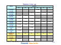
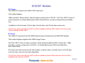
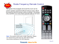
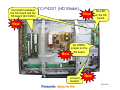
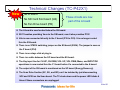
Technical Guide 2009-Plasma HD and FHD TV (12th Generation) Applies to models: TC-P42X1 TC-P50X1 TC-P42S1 TC-P46S1 TC-P50S1 Model TC-P42PX1 Panasonic Service and Technology Company National Training TTG090306CP/090306 Slide #1 Prepared by Cesar Perdomo Panasonic Service and Technology Company National Training "HDMI, the HDMI logo and High-Definition Multimedia Interface are trademarks or registered trademarks of HDMI Licensing LLC.“ Copyright 2009 by Panasonic Service and Technology Company All rights reserved. Unauthorized copying and distribution is a violation of law. Warning This service information is designed for experienced repair technicians only and is not designed for use by the general public. It does not contain warnings or cautions to advise non-technical individuals of potential dangers in attempting to service a product. Products powered by electricity should be serviced or repaired only by experienced professional technicians. Any attempt to service or repair the product or products dealt with in this service information by anyone else could result in serious injury or death. Slide #2 Table of Content Subject Topics Introduction Series Line-up Z1 - V10 Series G10 –S1 Series Z Series New Features Comparison Power Consumption Comparison Viera Technology Moving Picture Resolution 1080 Lines with 600Hz Sub-field Drive Moving Picture Resolution Sub-field Over 2,000,000:1 High Contrast (Native 40,000:1) Air Filter Wireless HD Radio Frequency Remote Controller TC-P42PX1 (HD Model) Technical Changes S – Series Full-HD Connectors/Boards Location Boards Description Standby Operation Standby Circuit Operation Power On Power On Operation Sub-Voltages Sub-Voltages Distribution 10 Blinks Condition Troubleshooting SOS Detect (Shutdown) SOS Blinking Timing Chart SOS Detect Block Diagram (TC-P42S1) Panel Drive SOS Detect Block Diagram (TC-P42S1) Panel Drive SOS Detect Block Diagram (TC-P42X1) Panel MPU SOS Detect Panel MPU SOS Detect (Continue) System PMU SOS Detect 2 Blinks Error Code Troubleshooting 2 Blinks Error Code Slide 4 5 6 7 8 9 10 11 12 13 14 15 16 17 18 19 20 21 22 23 24 25 26 27 28 29 30 31 32 33 34 35 36 37 38 39 40 41 Subject 3 Blinks – 4 Blinks Error Code 5 Blinks Error Code Troubleshooting a 5 Blinks Error Code 6 Blinks Error Code (TC-P42S1) 6 Blinks Error Code (TC-P42X1) 6 Blinks Error Code Circuit Explanation DRV RST Diagram (TC-P42S1) Driver Reset Circuit Operation DRV RST Block Diagram (TC-P42X1) 7 Blinks Error Code 8 Blinks Error Code (TC-P42S1) 8 Blinks Error Code Circuit Explanation 8 Blinks Error Code (TC-P42X1) 8 Blinks Error Code (TC-P42X1) Circuit Explanation 11 Blinks Error Code 11 Blinks Circuit Explanation Boards Isolation Procedure SC Board Isolation Procedure (TC-P42S1) SS Board Isolation Procedure (TC-P42S1) SS Board Isolation Procedure (TC-P42X1) SS – SD Boards Isolation SU and SD Boards Isolation Procedure SU Board Isolation Procedure SD Board Isolation Procedure Signal Process Block Signal Process Block Diagram Signal Process Explanation Service Notes Service Mode Self Check Self Check Menu Reset Procedure Glossary Slide 42 43 44 45 46 47 48 49 50 51 52 53 54 55 56 57 58 59 60 61 62 63 64 65 66 67 68 69 70 71 72 73 74 Slide #3 Topics Introduction Series Line-up Features Comparison Technical Changes Standby – Power On Operation Shutdown Circuit Explanation Troubleshooting Boards Isolation Service Notes Slide #4 Introduction Panasonic's 2009 line of VIERA HDTVs have improved their energy efficiency vs. last year's models, while also improving the overall picture performance of the HDTVs. This is list of features provided by Panasonic's 2009 line of VIERA HDTVs 1. Access to HD movie rental via Amazon Video-on-Demand. 2. Improved VIERA CAST interface by implementing quick keyword input (like a cell phone) to help retrieve favorite content faster and easier. 3. Panasonic HDTVs VIERA Link - a technology that utilizes HDMI-CEC (Consumer Electronics Control) and allows a consumer to operate all VIERA Link(TM: 65.38, -1.15, 1.73%) compatible A/V components using only the TV's remote control and helpful onscreen menus. 4. In addition to operating a VIERA HDTV, video source (Blu-ray and DVD player) and home theater receiver; VIERA Link permits operation of a network camera. A VIERA Link capable Network Camera BL-C210A can be connected to a VIERA HDTV and controlled via VIERA Link remote. Users can then watch their child, pet and/or property by installing the camera and networking to the VIERA HDTV via Ethernet cable. The BLC210A will be available in the United States in the summer of 2009. 1. Viewing of digital still photos and playback of AVCHD video recorded on SD card. 2. Panasonic New creation “Neo-PDP” line with a brighter panel, double luminance efficiency, deeper blacks with improved contrast ratio and 1080 TV lines of Moving Picture Resolution. 3. 8 THX certified VIEra models (The V10 series and the G10 series ) Note: THX certification ensures that each display can present all HD and standard definition content to the maximum resolution with accurate color and luminance levels. Slide #5 Series Line up SERIES MODELS 42” 46” 50” Z1 SERIES (Full HD) 58” 65” TC-V58V10 TC-V65V10 TC-P58S1 TC-P65S1 TC-P54Z1 V10 SERIES (Full HD) TC-V50V10 G15 SERIES (Full HD) TC-P42G15 TC-P46G15 TC-P50G15 G10 SERIES (Full HD) TC-P42G10 TC-P46G10 TC-P50G10 S1 SERIES (Full HD) TC-P42S1 TC-P46S1 TC-P50S1 U1 SERIES (Full HD) TC-P42U1 TC-P46U1 TC-P50U1 X1 SERIES (HD) TC-P42X1 TC-P50X1 C1 SERIES (HD) TC-P42C1 TC-P50C1 DERIVATIVE MODELS 42” PS SERIES (Full HD) PX SERIES (HD) 54” TC-42PS14 46” TC-V54V10 TC-P54G10 TC-P54S1 50” 54” TC-50PS14 TC-54PS14 58” 65” TC-50PS14 A new 54” model has been introduced for this year Slide #6 Z Series Z1/V10 Series The flagship VIERA plasma in 2009 is the Z1 series, with a revolutionary one inch thin panel design and Wireless HD connectivity to deliver the ultimate sleek, uncluttered HDTV viewing experience. VIERA CAST web menu with the new streaming HD movie rental capability via Amazon Video-onDemand. The Neo PDP design of the VIERA Z1 produces a brighter picture, deeper blacks, improved native contrast ratio (40,000:1) and Full-Time 1080 TV lines of motion resolution. 1080p resolution, a THX Certified Display; an Infinite Black panel; 600Hz Sub-field Drive; and VIERA Link, and VIERA Image Viewer for playing back digital still images and AVCHD videos recorded on SD Memory Cards. The Z1 series will be available in the summer of 2009 in the new TC-54Z1, 54-inch class screen size. V10 Series The VIERA V10 series are slim, 2-inch thin plasma HDTVs. Digital Cinema Color(TM: 65.38, -1.15, -1.73%) which helps to deliver all movie-essential colors, full THX Display certification. VIERA CAST web menu with Amazon Video on Demand services. The Neo PDP design features 1080p resolution; deeper blacks, improved native contrast ratio of 40,000:1; Full-Time 1080 TV lines of motion resolution; an Infinite Black panel; 600Hz Sub-field Drive; VIERA Link, and VIERA Image Viewer for playing back digital still images and AVCHD videos recorded on SD Memory Cards. Available in a 65-inch class, 58-inch class, 54-inch class, and a 50-inch class screen size. The 50-inch model with one-sheet-of-glass design will be available in May 2009 and the remaining models will be available in the summer of 2009. Slide #7 G10/S1 Series G10 Series The VIERA G10 features the VIERA CAST web menu. THX certified Display. 1080p resolution, deeper blacks, improved native contrast ratio of 40,000:1, Full-Time 1080 TV lines of motion resolution, an Infinite Black panel, 600Hz Sub-field Drive, as well as Game Mode and VIERA Link. Available in a 54-inch class, 50-inch class, 46-inch class, and 42-inch class screen size. The 42-inch, 46-inch and 50-inch HDTVs will be available in March 2009, while the 54-inch model will be available in May 2009. S1 Series The VIERA S1 represents the first VIERA plasma series to feature the new NEO PDP designs. THX certified displays together with VIERA Image Viewer. Full-Time 1080 TV lines of motion resolution, which eliminate traditional HDTV motion blur. 1080p resolution; a native contrast ratio of 40,000:1; an Infinite Black panel; 600Hz Sub-field Drive; and a Game Mode. 65" screen size with its own 65-inch class product, a 58-inch class, a 54-inch class, a 50-inch class a 46-inch class, and a 42-inch class diagonally). The 42-inch, 46-inch and 50-inch HDTVs will be available in March 2009 while the 54-inch will be available in the summer of 2009. Slide #8 X Series X1 Series The X1 VIERA HDTVs offer a 600Hz Sub-field Drive that delivers razor-sharp motion focus. VIERA Image Viewer for photos playback. VIERA Link control of all compatible A/V home entertainment components via a single remote. Improved native contrast ratio of 30,000:1, an Infinite Black panel, and a Game Mode. Available in a 50-inch class and 42-inch class. Slide #9 New Features Comparison Feature Z1 G15 G10 S1 Wireless HD X RF Remote Control X RS232 X X PC input X X X X X LAN Port X X X X X THX X X X X X Viera Cast X X X X X Viera Link With Network Camera X X X X X AVCHD/MPEG2/JPEG playback Thru SD Card X X X X X 1080 Lines Moving Picture Resolution X X X X X 900 Lines Moving Picture Resolution 720 Lines Moving Picture Resolution V10 U1 X1 C1 X PS PX X X X X X X Slide #10 Power Consumption Comparison HD FULL HD 2008 LCD 2008 Plasma 2009 Plasma TC-32LX85U Power Consumption Maximum 142 W Standby condition 0.6 W Weight 35.3 lb. TH-42PX80U (No Fans) Power Consumption Maximum 385 W Standby condition 0.3 W Weight 56.7 lb. TC-P42X1 (No Fans) Power Consumption Maximum 286 W Standby condition 0.3 W Weight 57.4 lb. TH-50PX80U (No Fans) Power Consumption Maximum 497 W Standby condition 0.3 W Weight 76.8 lb. TC-P50X1 (No Fans) Power Consumption Maximum 399 W Standby condition 0.3 W Weight 75 lb. TH-42PZ85U (With Fans) Power Consumption Maximum 573 W Standby condition 0.2 W Weight 66.1 lb. TC-P42S1 (With Fans) Power Consumption Maximum 485 W Standby condition 0.3 W Weight 57.4 lb. TH-50PZ85U (With Fans) Power Consumption Maximum 690 W Standby condition 0.2 W Weight 83.8 lb. TC-P50S1 (With Fans) Power Consumption Maximum 584 W Standby condition 0.3 W Weight 72.8 lb. TC-37LZ85U Power Consumption Maximum 222 W Standby condition 0.2 W Weight 48.6 lb. Slide #11 VIErA Technology Slide #12 New Moving Picture Resolution 1080 Lines with 600 Hz Sub-field Drive Sports and other fast-action scenes are stunningly clear. To improve the moving picture resolution, frames are generated at the sub-field level. With a frame generated each 1/60th of a second, images are created to match the motion. Slide #13 Moving Picture Resolution A static image is represented in its entirety 1920x1080. When the image moves from frame to frame, resolution is lost by the drivers and electronics behind the screen. Moving Picture Resolution 900 lines or more The resolution can be different between static versus dynamic. As you are watching moving images - that is the resolution that Panasonic quotes. It might be 1300 for a JPEG (just showing a comparison) 480 Hz Sub-field Drive 480Hz refers to the subfield drive. 8 subfields per frame x 60 frames per second = 480 subfields per second = 480Hz Slide #14 Sub-field A number of sub-fields overlap to depict the image in each frame. Panasonic technology detects movement in the image and reflects it in each individual subfield to achieve smooth playback with minimal blurring. What's Sub-field? Plasma TVs express a single frame of an image by using multiple images, each having a different gradation. These separate images are called sub-fields. Slide #15 Over 2,000,000:1 High Contrast (Native 40,000:1) New Series Z1, V10, G15, G10, S1, The shading in dimly-lit night scenes is beautifully rendered. A high contrast is achieved by NeoPDP technology. This newly developed, highly efficient panel creates a larger difference between maximum brightness (white) and minimum brightness (black). Slide #16 AR Filter Enjoy clearer images without bothersome reflections. Screen reflections are cut when viewing in bright rooms. This filter minimizes light reflections. Panasonic's unique low-reflection filter greatly reduces the reflected light intensity compared with the incident light intensity. Slide #17 New Wireless HD™ View HD images with wireless operation. This function sends high-resolution, full-HD data over a wireless connection. It enables a flexible VIERA layout to match any room interior. *A special receiver is required to use WirelessHD™. The usage distance and installation environment for the Wireless HD™ System and the effect that other machines will have on it are presently being tested, and the system performance is being confirmed. The actual usage distance might be shorter than the recommended distance due to physical obstacles between the transmitter and receiver, the surrounding environment, or the building structure. With regard to the installation environment, should the Wireless HD™ System be installed in hot areas or areas that radiate heat, video and audio performance can be adversely affected and the system may even malfunction. Also, the incorrect placement of the transmitter and receiver can lead to picture and sound scrambling and interruption, and general poor performance. With regard to the effect that other machines will have on the system, should the wireless transmitter or receiver be placed close to a telephone or microwave oven, normal operation may be prevented due to signal interference. Slide #18 New Radio Frequency Remote Control The signals that propagate all around the room can be used to operate equipment without having to worry about the direction that the remote control is pointed. This allows easy operation of a Tuner that is placed inside an AV rack. Note: This remote control uses 2.4GHz frequency. Please do not place this control near any other device which may receive interference from the frequency. Slide #19 Connection between the SC board and the SS board SS board (SC3-SS3) TC-P42X1 (HD Model) New No LED on the SS board New New No STB5V jumper on the SS board A board location New Slide #20 Technical Changes (TC-P42X1) New No D board No SD Card Slot board (GS) These circuits are now part of the A board No Fan Drive board (PB) The A board is now located below the SS board. SS11 besides providing Vsus to the SS board, now it also provides P15V Vda is now connected directly to the C board (P35 to C25). It is no longer routed thru the SS board. There is no STB5V switching jumper on the SS board (SS34). The jumper is now on the P board (P34) There is no relays click at plug in. There is a cable between the SC board and the SS board. The Key input line for CH UP, CH DWN, VOL UP, VOL DWN, Menu, and INPUT/OK operations is now routed thru the C1 board before it’s connected to the A board The output of the SS board is monitored on the SC board (Energy Recovery) The Scan Drive Section (SC, SU, and SD) can’t be isolated by just disconnecting SC2 and SC20 on the Scan board. The TV shuts down and the power LED blinks 6 times if these connectors are unplugged Slide #21 S – Series (Full-HD) Slide #22 Connectors/Boards Location (TC-P42S1) Slide #23 Boards Description Board Description Board Description A Speaker out, Sound Processor, AV Terminal, AV Switch, DC-DC Converter, Digital Signal Processor, Microcomputer, HDMI Interface, Peaks Lite 2, Full HD, (Newly Added SD Card Slot, Fan Control, Format Converter, Plasma AI, Sub-Field Processor) P Power Supply C1 Data Driver (Right) S Power Switch C2 Data Driver (Left) SC Scan Drive GK Key Switch (CH UP, CH DWN, VOL UP, VOL DWN, MENU, INPUT/OK SD Scan Out (Lower) K Remote Receiver, Power LED SU Scan Out (Upper) Slide #24 Standby Operation Slide #25 Standby Circuit Operation When the TV is plugged in: AC is applied to the standby circuit in the power supply to produce STB5V. The STB5V is provided to the A board via connectors P7 (Pin 5) and P25 (Pin 9). Connector P25 is connected to connector A25 on the A board and connectors P6 and P7 are both connected to connector A6 on the A board. The STB5V connected to A25 is not used during standby operation. The STB5V from pin 5 of connector P7 is connected to pin 13 of connector A6 and is applied to a 3.3V regulator to power the Main CPU (IC1100) on the A board. This energizes the microprocessor (CPU) and gets it ready for program execution. The 3.3V from the voltage regulator besides being applied to the CPU, is also applied to the remote control receiver and the power LED on the K board through connector A1/K1 (pin 3). If the STB5V is missing, the TV is dead (No power) Slide #26 Power On Slide #27 Power On Operation The power command from the power switch on the S board or the remote control receiver on the K board is provided to the Main CPU on the A board (IC1100) thru connector A1. The CPU on the A board outputs the “TV_SUB_ON” Command (3.2V) and the PANEL_STB_ON” command (3.2V). The “TV_SUB_ON” command is provided to pin 6 of connector P7 of the power supply through pin 14 of connector A6 of the A board to develop the F_STB+15V. At this time the relays on the power supply are triggered and a “click” sound can be heard. The F+15V from the P board is applied to several voltage regulator (IC5603, IC5401, and IC5607) on the A board. The voltage outputs from these ICs are called SUB5V, SUB9V, SUB3.3V, SUB1.8V, SUB1.3V, and BT30V. They used by various circuits on the A board. To avoid catastrophic failures, they are monitored by an SOS Detect circuit (IC5480) for over-voltage and over-current conditions. This SOS Detect circuit is controlled by the TV_SUB_ON command from the Main CPU (IC1100). Any abnormalities of the SUB5V, SUB9V, or BT30V triggers the SOS circuit. The TV shuts down and the power LED blinks 10 times. The “PANEL_STB_ON” is used to turn on the 3.3V regulator (IC9004) on the A board. The output voltage is applied to the “Panel” CPU on the A board (Formerly located in the D board). The Panel CPU on the A board outputs the “PANEL_MAIN_ON” Command (3.2V) to pin 11 of connector P25 on the P board. The PANEL MAIN ON command turns on the power supply circuit that outputs the Vsus, Vda, 15V, and 5V. Slide #28 Sub-Voltages Slide #29 Sub-Voltages Distribution On previous generations these voltages were present for approximately 15 seconds after connecting the TV to the AC line. This does not apply to this year’s models. These voltages are called sub-voltages and they are only used by the A board. The sub-voltages are developed when the power is turned on. The F+15V from the P board is the source that supplies the DC-DC converter circuit (IC5401, IC5603 and IC5401) in the A board. The A board outputs 9V, 5V, 3.3V, 1.8V. The BT30V is generated by IC5480. A 10 blinks code from the power LED indicates abnormalities in any of these voltages including the F+15V. Slide #30 10 blinks Condition Troubleshooting Since the Sub voltages are only present after the power has been turned on, there will not be a 10 blinks condition at plug-in for the 2009 models. These 3 conditions can cause the TV to shutdown and the power LED to blink 10 times 1. Missing/Shorted F_STB_15V, SUB9V, SUB5V, and BT30V 2. Wrong diagnostic by the A board Note: When taking voltage reading, place the voltmeter probe at the test point, component, or connector’s pin indicated before connecting the TV to the AC line. This will ensure voltage reading accuracy before the TV shuts down. To troubleshoot a PDP TV that is shutting down and the power LED blinks 10 times: Find out if 15V is output at pin 7,8,or 9 of connector P6 of the P board. If no voltage is output, the P board may be defective. If the F_STB_15V voltage is OK, it’s likely that the A board is defective. Slide #31 SOS Detect (Shutdown) When an abnormality occurs in the unit, the “SOS Detect” circuit is triggered and the TV shuts down. The power LED on the front panel will flash a pattern indicating the circuit that has failed. If the power LED continues to blink even after the TV is unplugged, press and hold the power switch on the TV for a few seconds until the LED turns off. Slide #32 SOS Blinking Timing Chart Slide #33 SOS Detect Block Diagram (TC-P42S1) Slide #34 Panel Drive SOS Detect Block Diagram (TC-P42S1) Slide #35 Panel Drive SOS Detect Block Diagram (TC-P42X1) Slide #36 Panel MPU SOS Detect • • • • • • • Protection circuits are incorporated in the unit to prevent the failure of a single circuit or component from creating catastrophic damage. A shutdown condition occurs when there is an over voltage, a short or a drop in any of the voltage lines. Also the shutdown circuit is triggered when the fans are drawing more current than normal. Normally the CPU of the D board and the CPU of the A board detect when a shutdown condition has been triggered. When an abnormality has occurred, the unit’s protection circuit operates and the TV is reset to the standby mode. At this time, the defective block can be identified by the number of blinks of the POWER LED on the front of the unit. The Panel MPU IC9003 of the A board (Located on the D board on previous generations) detects conditions that make the power LED blinks1, 2, 3, 4, 5, 6, 7, 8, or 9 times. The Main MPU IC1100 of the A board detects conditions that make the power LED blinks 10, 11, 12, and 13 times. The number of times that the POWER LED blinks indicates the areas where a problem is suspected. • 1 Blink SOS: Communication error with IC9003. • 2 Blinks SOS: Pin 62 of the CPU IC9003 monitors the 15V line. During normal operation pin 62 is kept high. If the 15V line is missing or shorted, a low is provided to pin 62. As a result, the unit shuts down and the power LED blinks 2 times. • 3 Blinks SOS: IC9805 is a 3.3V regulator located on the D board. Its output is monitored by IC9003. If the 3.3V is not present at pin 61, the CPU (IC9003) shuts down the unit. The power LED blinks 3 times. Slide #37 Panel MPU SOS Detect (Continue) 4 Blinks SOS: When an over voltage condition of the voltage lines from the power supply occurs, pin 12 of connector P25 goes high. This high is provided to pin 67 of IC9003 of the A board triggering the “POWER SOS” circuit. When this happens, the TV shuts down and the power LED blinks 4 times. Primarily the P board causes 4 blinks, followed by the A board. 5 Blinks SOS: Pin 60 of the CPU IC9003 monitors the 5V line. During normal operation, pin 60 is kept high. If the 5V line is missing or shorted, a low is provided to pin 60. As a result, the unit shuts down and the power LED blinks 5 times. 6 Blinks SOS: Pin 65 of the CPU IC9003 monitors the status of the SC board. During normal operation, a low is applied to pin 65. If the SC board becomes defective, a high is provided to pin 65. As a result, the unit shuts down and the power LED blinks 6 times. The TC-P42X1 series monitors the sustain board output. This signal is connected to the recovery circuit in the SC board. Any abnormality on the sustain board will trigger the 6 blinks code. 7 Blinks SOS: Pin 68 of the CPU IC9003 monitors the status of the SC, SU, SD board. During normal operation, a low is applied to pin 68. If the SC, SU, or SD board becomes defective, a high is provided to pin 68. As a result, the unit shuts down and the power LED blinks 7 times. 8 Blinks SOS: Pin 66 of the MPU IC9003 monitors the status of the SS board. During normal operation, pin 8 of connector SS33 outputs a low to pin 66. If the SS board becomes defective, a high is provided to pin 66. As a result, the unit shuts down and the power LED blinks 8 times. 8 Blinks condition is also caused when the connections between the panel’s flex-cables and the sustain board is broken. Slide #38 System MPU SOS Detect 10 Blinks SOS: IC5401 generates the SUB9V, IC5607 generates the SUB5V, and IC5480 generates the BT30V. The SUB9V, BT30V, and SUB5V from these ICs are monitored by IC1100. Any abnormality on these voltages (Including the F_STB15V), triggers the shutdown circuit and the MPU shuts down the unit. The power LED blinks 10 times. 11 Blinks SOS: The ventilation fans are monitored for proper operation. If one of the fans opens or increases resistance, the resulting current change is applied to pin 36 of the main CPU (IC1100). This triggers the Fan SOS and the TV shuts down. The power LED blinks 11 times. 12 Blinks SOS: The operation of the audio power amplifier IC2109 is monitored. If the audio output circuit develops a short to ground, a high is output to pin 37 of the MPU (IC1100), triggering a SOS condition. The power LED blinks 12 times. 13 Blinks SOS: When the TV is turned on, a system check is performed through the IIC0 bus line. The system MPU and IC8001 (Seine 3LV) communicates and if an abnormality is detected, the TV shuts down and the power LED blinks 13 times. Slide #39 2 Blinks Error Code These 3 conditions can cause the TV to shutdown and the power LED to blink 2 times 1. Missing P15V 2. A short of the P15V 3. Wrong diagnostic by the A board Slide #40 Troubleshooting 2 Blinks Error Code When troubleshooting a PDP TV that is shutting down and the power LED blinks 2 times: Find out if 15V is output at pin 1 of connector P6 of the P board. If 15V is present, it’s likely that the A board is defective. If no voltage is output, determine if this is caused by the P board or the boards using the P15V. The boards connected to the P15V can only affect the P15V if there is a short circuit drawing excessive current. To check for a short circuit, measure the resistance between pin 1 of connector P6 and ground (Chassis). If P15V is shorted, find out if the short is coming from the P board or if it’s coming from any of the other boards that the 15V volt is connected to. If the P board is OK, disconnect the connectors providing the P15V to all these boards while measuring resistance between pin 1 of connector P6 and ground. The defective board is found when the connector that provides the P15V to that board is removed and the short circuit is no-longer present. Slide #41 3 Blinks/4 Blinks Error Code 3 Blinks Error Code Since the IC (IC9805) that generates the monitored 3.3V for 3 blinks condition and the IC (IC9003) that detects this condition are both located on the A board, then the A board is the only suspect when the TV shuts down and the power LED blinks 3 times. Replace the A board. 4 Blinks Error Code Primarily the P board causes 4 blinks, followed by the A board. To troubleshoot a 4 blinks condition, measure the voltage at pin 12 of connector P25. If the voltage goes high, the P board is the problem. If the voltage stays low, then the A board is the problem. Slide #42 5 Blinks Error Code These 4 conditions can cause the TV to shut down and the power LED to blink 5 times 1. Missing P5V 2. A short of the P5V 3. A short of the Vda line (Note: missing Vda from the P board does not cause 5 blinks) 4. Wrong diagnostic by the A board Slide #43 Troubleshooting a 5 Blinks Error Code When troubleshooting a PDP TV that is shutting down and the power LED blinks 5 times: Find out if pins 1 or 2 of connector P35 are shorted to ground. If shorted, possibly the panel is bad. If there is no short circuit, proceed to check the P5V line. Find out if 5V is output at pin 5 of connector P25 of the P board. If no voltage is output, measure resistance between pin 5 of connector P25 and ground (Chassis). If P5V is shorted, find out if it’s created on the P board or if it’s created on any of the other boards that the 5V volt is connected to. If the P board is OK, disconnect the connectors providing the P5V to all these boards while measuring resistance between pin 5 of connector P25 and ground. The defective board is found when the connector that provides the P15V to that board is removed and the short circuit is no-longer present. Slide #44 6 Blinks Error Code (TC-P42S1) The Scan and Sustain voltages on the SC and SS boards are monitored by an SOS Detect circuit. The energy recovery circuit in the SC board is monitored by a comparator (Error detect IC16581). The output voltage is compared to 2 reference voltages derived from the P15V. If the output of this circuit drops below 5.2 or goes above 11.8V, the output of the comparator IC6581 goes high to trigger the “Energy Recovery” SOS line. This high is provided to the Panel CPU on the A board. The TV shuts down and the power LED blinks 6 times. Slide #45 6 Blinks Error Code (TC-P42X1) Slide #46 6 Blinks Error Code Circuit Explanation The sustain drive circuit on the sustain board is not a complete circuit. There is a part of this circuit in the SC board. The cable between connector SS3 on the sustain board and SC3 on the scan board links these 2 circuits The section of the sustain drive circuit located on the scan board uses Vsus for complete operation of the sustain output circuit. The energy recovery circuit in the SC board uses a comparator (Error detect IC16581) to monitor the operation of the scan and sustain output circuits . The output voltage is compared to 2 reference voltages derived from the P15V. If the output of this circuit drops below 5.2 or goes above 11.8V, the output of the comparator IC6581 goes high to trigger the “Energy Recovery” SOS line. This high is provided to the Panel CPU on the A board. The TV shuts down and the power LED blinks 6 times. Slide #47 DRV RST Block Diagram (TC-P42S1) Slide #48 Driver Reset Circuit Operation The DRV RST circuit of the A board is used to monitor the physical connection of the A board to the C board. DRV RST input to IC9500 and IC9003 must be high for the unit to operate. The A board provides the 5V source needed to power the C boards. On the C1 board and the C2 board, the 5V is routed back to the D board via connector C11/A31, C21/A32 to activate the 5V SENSE circuit. A voltage divider in the C1 board develops a voltage drop that causes the collector of transistors Q9301 to become low. As a result, the base voltage of Q9302 also becomes low causing its collector to go high. The output voltage is applied to IC9500 and IC9003 as DVR RST. When the 5V SENSE circuit does not detect 5V from the C1 board and the C2 board, the DVR RST output becomes low. The unit goes into shutdown and the power LED blinks 6 times. Slide #49 DRV RST Block Diagram (TC-P42X1) Slide #50 7 Blinks Error Code The SC board has 2 SOS detect circuits, energy recovery and floating ground section. When the energy recovery circuit is triggered, the TV shuts down and the power LED blinks 6 times. The floating ground circuit monitors the scan circuit output, the 15V_F, the scan_pro, Vscan, and the physical connection between the SC board and the SU/SD board (CHA). If any abnormality occurs on any of these lines or Vsus is missing, the TV shuts down and the power LED blinks 7 times. If any of the connectors between the SC and the SU/SD board is open, the TV also shuts down and the power LED blinks 7 times. Slide #51 8 Blinks Error Code (TC-P42S1) Slide #52 8 Blinks Error Code Circuit Explanation There is an extra SOS Detect circuit in the Sustain board. This circuit is used to monitor for physical connection between the panel and the SS board. Under normal condition, Q16280 is on. When Q16280 is on, a low is provided to the anode of D16280 (D280). If one of the FPC cables is open, Q16280 turns off and a high is provided to the anode of D16280 (D280). This high is provided to pin 66 of the CPU in the A board. When this happens, the TV shuts down and the power LED blinks 8 times. The energy recovery circuit is also used to monitor the operation of the sustain drive circuit. If this circuit is triggered, a high is provided to the anode of D16255 to trigger a shutdown. To determine if the 8 blinks is caused by the A board, SS board, or the Panel: • Isolate the SS board and check if the TV stays on when it’s turned on. • If the TV does not stay on after disconnecting the SS board, the A board is defective. • If the TV stays on, then the SS or the Panel is defective. • If the anode of D16280 (D280) is high (2.7V) at the time the unit shuts down, the Panel might be defective. (Check for loose connection between the flex-cables and the SS board). • If the anode is low, the SS board is defective. Slide #53 8 Blinks Error Code (TC-P42X1) SS_Flexible Printed Circuit (FPC)_Detect (SOS8_SS) (TC-P42X1) Slide #54 8 Blinks Error Code (TC-P42X1) Circuit Explanation On this model, only the circuit used to monitor for physical connection between the panel and the SS board is used to trigger an 8 blinks condition. The energy-recoverycircuit portion used to monitor the operation of the sustain drive circuit is located on the SC board. Under normal condition, Q16280 is on. When Q16280 is on, a low is provided to the anode of D16280 (D280). If one of the FPC cables is open, Q16280 turns off and a high is provided to the anode of D16280 (D280). This high is provided to pin 66 of the CPU in the A board. When this happens, the TV shuts down and the power LED blinks 8 times. To determine if the 8 blinks is caused by the A board, SS board, or the Panel: • Isolate the SS board and check if the TV stays on when it’s turned on. • If the TV does not stay on after disconnecting the SS board, the A board is defective. • If the TV stays on, then the SS is bad, the FPC cables are open, or the Panel is defective. To isolate the SS board for 8 blinks condition: Remove SS23 and see if the TV stays on Slide #55 11 Blinks Error Code Slide #56 11 Blinks Circuit Explanation The ventilation fans are monitored to be sure they are operating properly. If one of the fans stops or its resistance increases, the resulting current change is applied to pin 36 of the main CPU. The fan drive circuit is located in the A board. The Panel-Main-On command from pin 75 of the Panel MPU (IC9003) turns on the fan control IC (IC5740). An increase in temperature of the TV is detected by the temperature sensor (IC4800). This IC communicates with the main MPU (IC1100) through the IIC0 bus line. To control the speed of the fan, a Fan-Max command from pin 44 of IC1100 is output to the fan control IC5740. To keep the unit cool, the fan control voltage output from IC5740 to the fans ranges between 7V and 11V. If this voltage exceeds 12V, D5749 conducts. The resulting voltage is then fixed at 3.3V by D5751 and it is applied to pin 36 of IC1100 to trigger the SOS condition. The TV shuts down and the power LED blinks 11 times. If any of the fans becomes defective or the fan connector is removed, A high is output at pin 6 or 9 of the fan connector (A30) to forward bias the inline diode. The DC output of the diode is provided to pin 36 of the MPU (IC1100) to trigger the SOS condition. Slide #57 Boards Isolation Procedure Caution: Do not let the TV run for more than 30 seconds while connectors or boards are disconnected. Slide #58 SC Board Isolation Procedure (TC-P42S1) When the SC board is suspected to be the cause of a 6 or 7 blinks condition, it can be isolated for confirmation. To isolate the Scan Drive Section (SC, SU, and SD board), remove connectors SC2 (Vsus) and SC20 (P+15V, P+5V, and scan pulses) from the SC board and connector SS33 from the sustain board. When this is done, the display is completely black (No picture) Slide #59 SS Board Isolation Procedure (TC-P42S1) To determine if the Sustain board is causing a 8 blinks condition: Unplug connector SS11 and connector SS33. Press the power switch. If the TV no longer blinks 8 times, then the SS board is defective. Note 2: In order to get to SS33, the A board has to be removed. Remove the 3 screws holding the A board block assembly in place. Slide #60 SS Board Isolation Procedure (TC-P42X1) To determine if the Sustain board is causing a 8 blinks condition: Unplug connector SS23. Press the power switch. If the TV no longer blinks 8 times, then the SS board is defective. Note 2: In order to get to SS23, the A board has to be removed. Remove the 3 screws holding the A board block assembly in place. Slide #61 SU/SD Boards Isolation Slide #62 SU and SD Boards Isolation Procedure Beginning last year (2008), the new plasma models are now designed not to turnon if either the SU or SD board is disconnected. Disconnecting either causes the unit to shutdown and the power LED to blink 7 times. Unplugging any of the connectors SC41/SU41, SU11/SD11, and SC42/SD42, opens the interlocked connection between VF_GND and CHA on the SC board. This floats point “CHA” and Q16471 turns on. IC16561 outputs a high to pin 21 of connector SC20 triggering shutdown. To isolate the SU and SD boards at the same time is not necessary to remove the boards: • Remove the 4 VF_GND screws (2 on the SU board and 2 on the SD board). • Unplug connectors SC41, SC46, and SC42 on the SC board. • Place a jumper between pins 1 and 2 of the empty connector SC50. When this is done, the display is completely black (No picture) Note: This procedure could be useful when troubleshooting 7 blinks problems. Slide #63 SU Board Isolation The 2008 and 2009 plasma models are now designed not to turn-on if either the SU or SD board is disconnected. Disconnecting either causes the unit to shutdown and the power LED to blink 7 times. Unplugging SC41/SU41, SU11/SD11, and SC42/SD42, opens the interlocked connection between VF_GND and CHA on the SC board. This floats point “CHA” and a high is output to connector SC20 triggering shutdown. To isolate the SU board: • Remove the 2 VF_GND screws on the SU board only. • Unplug connector SC41 on the SC board and SU11 on SU board. • Place a jumper between pins 1 and 2 of the empty connector SC50. Note: This procedure could be useful when troubleshooting 7 blinks problems. Slide #64 SD Board Isolation The 2008 and 2009 plasma models are now designed not to turn-on if either the SU or SD board is disconnected. Disconnecting either causes the unit to shutdown and the power LED to blink 7 times. Unplugging SC41/SU41, SU11/SD11, and SC42/SD42, opens the interlocked connection between VF_GND and CHA on the SC board. This floats point “CHA” and a high is output to connector SC20 triggering shutdown. To isolate the SD board: • Remove the 2 VF_GND screws on the SD board only. • Unplug connector SC46 and SC42 on the SC board and SU11 on SU board. • Place a jumper between pins 1 and 2 of the empty connector SC50. Note: This procedure could be useful when troubleshooting 7 blinks problems. Slide #65 Signal Process Block Slide #66 Signal Process Block Diagram Slide #67 Signal Process Explanation The main function of the A board is to select and process one of the incoming video signals. Video inputs 1 and 2, Component Video Inputs 1 and 2, PC input, and the composite video output of the tuner are all are connected to IC3001 for selection. The video output signal of the switch can be in any of the three formats: Video, Y/C, or Y, Pb, Pr. The selected output enters IC8001. A comb filter inside IC8001 converts the composite video signal of the main picture to Y and C (luminance and chrominance) signals. S-Video, which is already Y/C separated, simply passes through the comb filter. At the completion of this process, the format of the composite or S-Video signal is now the same as a digital 480i component signal. If the incoming video is in the 480p, 720P, or 1080i format, the Y, Pb, and Pr signals undergo A/D (analog to digital) conversion only. The 10 bit YUV data is provided to a video switch. The HDMI receiver section of IC4503 converts the incoming HDMI signals to a YUV video signal. The output of the switch is provided to another switch located inside the PEAKS LITE IC, IC8001. Digital television reception of the tuner is output in the form of an IF (Intermediate Frequency) signal The transport stream from the tuner enters the VSB I/F (Interface) section of IC8001 where the video signal is extracted and converted to YUV data. The output is provided to the Video Input I/F for selection. The JPEG data of the SD card enters the JPEG I/F section of IC8001 for conversion into YUV data and output to the Video Input I/F circuit. The video input interface outputs the selected picture data to the video process circuit. This Video Process section of the IC performs all picture control operations such as brightness, contrast, color, tint, etc. On Screen Display data such as channel numbers, Digital TV closed caption, and picture adjustments are mixed with the video data. LVDS (Low Voltage Differential Signaling) is output to IC9900 (Plasma AI, H/V Sync Control, and Sub-field Processor). The Plasma AI (Adaptive brightness Intensifier) circuit analyzes the video program level for the distribution of dark and bright components. This circuit is also used to speed up the scanning process and control the number of sustain periods. This increases the brightness and improves the contrast ratio. The data drive signals are output to the C1 and C2 boards. The C1 board drives the right portion of the panel and the C2 board drives the left portion IC9500 provides the scan, sustain and data drive signals. The scan pulses are output to the SC board. The sustain pulses are output to the SS board. The main MCU handles all video applications. It serves as the controller that monitors all operations of the TV section (not display) of the unit. Slide #68 Service Notes Slide #69 Service Mode While pressing [VOLUME ( - )] button of the main unit, press [INFO] button of the remote control three times within 2 seconds. Key command [1] button...Main items Selection in forward direction [2] button...Main items Selection in reverse direction [3] button...Sub items Selection in forward direction [4] button...Sub items Selection in reverse direction [VOL] button...Value of sub items change in forward direction ( + ), in reverse direction ( - ) How to exit: Switch off the power with the [POWER] button on the main unit or the [POWER] button on the remote control. Slide #70 Self Check 1. Checks the communication IIC bus lines 2. Provides a SOS History To ToAccess Accessthe theSelf-Check Self-CheckMode, Mode,turn turnthe theTV TVon onand andwhile whilepressing pressing “VOLUME “VOLUME((--)”)”button buttonon onthe themain mainunit, unit,press pressthe the“OK” “OK”button buttonon onthe the remote remotecontrol controlfor formore morethan than33seconds. seconds. TV volume down & OK on remote only does a basic IC self check. It does NOT clear any unit settings. It does not clear channel programmed settings, picture settings, channel labels, LOCK mode settings, or password. Using this method, it shows the unit firmware version (Peaks 1.050 and GenX 1.00) and it checks IC communications ONLY. This is more useful to identify the firmware version without having to decode the info in the setup menu About/Version screen. To ToExit Exitthe theSelf-Check Self-CheckMode, Mode,Press Pressand andhold holdthe thePower Powerbutton buttonon on the theTV TVfor for55seconds secondsor ordisconnect disconnectthe theAC ACcord cordfrom fromthe thewall walloutlet. outlet. Slide #71 Self Check Menu Slide #72 Reset Procedure Note: All customer programmed parameters will be erased. Reset forces the TV to factory shipment setting. To reset the TV: Press and hold the “VOLUME ( - )”button on the TV and press the “MENU” button on the remote control for more than 3 seconds. To Exit: Disconnect the AC cord from wall outlet. Slide #73 Glossary Resolution Resolution is a combination of values that express the quality of displayed images. A display's resolution is indicated by the number of dots in the horizontal and vertical directions of the screen, such as 1024 x 768 dots. Higher values indicate clearer, sharper image reproduction. The larger the screen size, the higher the required resolution. HD (high-definition) panel The HD panel has a resolution of 1,366 x 768 pixels and an aspect ratio of 16:9. It is designed for displaying the beautiful images of digital, high-definition broadcasts. Full HD (high-definition) panel The term "full-HD panel" refers to 1,920 x 1,080-pixel panels that display progressive images of fullspecification HDTV signals without the use of up sampling. Number of pixels The number of pixels indicates the resolution of the Image. The number of pixels of a digital image is expressed by the product of the number of pixels (dots) in the horizontal direction and the number of pixels (dots) in the vertical direction. The higher the number of pixels, the better the image quality. For plasma TVs and LCD TVs, the number of pixels is sometimes expressed by the following equation: number of pixels in horizontal direction x number of pixels in vertical direction x 3 (R, G, B). Pixel A pixel is a tiny dot that forms the smallest basic unit of a displayed image. Digital images are composed of pixels, with all of the text and images displayed on the screen consisting of dots. Digital images are usually rendered by square pixels arranged vertically and horizontally in an orderly manner. Plasma panel A key component of the plasma display. A plasma panel is a collection of millions of tiny fluorescent lights. By firing these lights on and off at a rapid rate, the plasma panel produces images. Slide #74 Glossary THX THX is a trade name of a high-fidelity sound reproduction standard for movie theaters, screening rooms, home theaters, computer speakers, gaming consoles, and car audio systems. THX stands for Tomlinson Holman's eXperiment. The THX system is not a recording technology, and it does not specify a sound recording format: all sound formats, whether digital (Dolby Digital, SDDS) or analog (Dolby Stereo, Ultra-Stereo), can be "shown in THX." THX is mainly a quality assurance system. THX-certified theaters provide a high-quality, predictable playback environment to ensure that any film soundtrack mixed in THX will sound as near as possible to the intentions of the mixing engineer. AVCHD Advanced Video Codec High Definition is a high-definition and standard-definition recording format for use in digital tape-less camcorders and digital cameras. It is based on the H.264/MPEG-4 AVC video compression standard. Audio is stored in compressed form (Dolby AC-3). The container format for the audio and video is MPEG transport stream. H.264 H.264 is a standard for video compression, and is equivalent to MPEG-4 Part 10, or MPEG-4 AVC (for Advanced Video Coding). As of 2008, it is the latest block-oriented motion-compensation-based codec standard. The final drafting work on the first version of the standard was completed in May 2003. The intent of the H.264/AVC project was to create a standard capable of providing good video quality at substantially lower bit rates than previous standards (e.g. half or less the bit rate of MPEG-2, H.263, or MPEG-4 Part 2), without increasing the complexity of design so much that it would be impractical or excessively expensive to implement. YUV YUV is used for a specific analog encoding of color information in television systems Y' stands for the luma component (the brightness) and U and V are the chrominance (color) components. Slide #75 Glossary YUV Is The color encoding system used for analog television worldwide (NTSC, PAL and SECAM). The YUV color space differs from RGB, which is what the camera captures and what humans view. Composite Video and S-video The original TV standard combined luma (Y) and both color signals (B-Y, R-Y) into one channel, which uses one cable and is known as "composite video." An option known as "S-video" or "Y/C video" keeps the luma separate from the color signals, using one cable, but with separate wires internally. S-video is a bit sharper than composite video. Component Video When luma and each of the color signals (B-Y and R-Y) are maintained in separate channels, it is called "component video," designated as YPbPr when in the analog domain and YCbCr when it is digital. Slide #76 The End Slide #77