1
VQTB0328
Before operating this product, please read the instructions carefully and save this manual for
future use.
取扱説明書
マルチパーパスカメラ
品番
AK-HC1800N
Model No.
AK-HC1800N
保証書別添付
Multi Purpose Camera
Operating Instructions
このたびは、パナソニック製品をお買い上げいただき、まことにありがとうござ
います。
取扱説明書をよくお読みのうえ、正しく安全にお使いください。
ご使用前に「安全上のご注意」
(3 ~ 7ページ)を必ずお読みください。
保証書は「お買い上げ日・販売店名」などの記入を確かめ、取扱説明書ととも
に大切に保管してください。
VQTB0328
-2-
もくじ
付属品 ....................................................... 2
安全上のご注意 ........................................ 3
個人情報の保護について ........................ 7
概要 ........................................................... 8
特長 ........................................................... 8
使用上のお願い ........................................ 9
各部の名称とはたらき ......................... 10
取り付けかた ......................................... 15
■レンズの取り付けかた ................. 15
■カメラハウジング、回転台、
三脚などへの取り付けかた ...... 15
システムの組みかた ............................. 16
■構成例1:
カメラコントローラーの接続 ... 16
■構成例2:High-Speed
P/Tシステム(1).................... 17
■構成例3:High-Speed
P/Tシステム(2).................... 18
■構成例4:AW-RP655または
AW-RP555からの制御 .......... 19
■AW-CB400からコントロールする
場合 ............................................ 20
■AW-RP655からコントロールする
場合 ............................................ 21
■AW-RP555からコントロールする
場合 ............................................ 22
■AW-CB400、AW-RP655、
AW-RP555と直接接続する場合
のケーブル配線仕様................ 23
操作の手順 ............................................. 24
調整のしかた .........................................
■フランジバック調整 .....................
■レンズ内のアイリスゲイン
ボリューム調整 .........................
■ホワイトバランス調整 .................
■色温度とホワイトバランス
調整(参考)...............................
■ブラックバランス調整 .................
■ゲンロック調整 .............................
25
25
25
26
26
27
27
インテリジェント機能について .......... 28
メニュー項目の設定 .............................
■メニューの表示方法 .....................
■TOPメニュー ................................
MAINTENANCEメニュー ..........
SETTINGメニュー .......................
CAMERA IDメニュー .................
FILE OPERATIONメニュー ......
■メニュー一覧 .................................
indicates safety information.
30
30
30
31
46
64
65
66
外形寸法図 ............................................. 70
定格 ........................................................ 71
保証とアフターサービス ..................... 72
Warning:
To assure continued FCC emission limit compliance, the user must use only
shielded interface cables when connecting to external units. Also, any
unauthorized changes or modifications to this equipment could void the user’s
authority to operate it.
FCC Note:
This equipment has been tested and found to comply with the limits for a class A
digital device, pursuant to Part 15 of the FCC Rules. These limits are designed
to provide reasonable protection against harmful interference when the
equipment is operated in a commercial environment. This equipment generates,
uses, and can radiate radio frequency energy, and if not installed and used in
accordance with the instruction manual, may cause harmful interference to radio
communications. Operation of this equipment in a residential area is likely to
cause harmful interference in which case the user will be required to correct the
interference at his own expense.
For CANADA
This class A digital apparatus complies with Canadian ICES-003.
Cet appareil numérique de la classe A est conforme à la norme
NMB-003 du Canada.
The exclamation point within an equilateral triangle is intended to alert
the user to the presence of important operating and maintenance
(service) instructions in the literature accompanying the appliance.
The lightning flash with arrowhead symbol, within an equilateral triangle,
is intended to alert the user to the presence of uninsulated “dangerous
voltage” within the product’s enclosure that may be of sufficient magnitude
to constitute a risk of electric shock to persons.
CAUTION: TO REDUCE THE RISK OF ELECTRIC SHOCK,
DO NOT REMOVE COVER (OR BACK).
NO USER SERVICEABLE PARTS INSIDE.
REFER TO SERVICING TO QUALIFIED SERVICE PERSONNEL.
付属品
RISK OF ELECTRIC SHOCK
DO NOT OPEN
本書 ........................................................... 1
CAUTION
レンズキャップ ........................................ 1
フィルター ................................................ 2
-2-
WARNING:
•TO REDUCE THE RISK OF FIRE OR ELECTRIC SHOCK, DO NOT EXPOSE
THIS APPARATUS TO RAIN OR MOISTURE.
•THE APPARATUS SHALL NOT BE EXPOSED TO DRIPPING OR SPLASHING
AND THAT NO OBJECTS FILLED WITH LIQUIDS, SUCH AS VASES, SHALL
BE PLACED ON THE APPARATUS.
CAUTION:
TO REDUCE THE RISK OF FIRE OR SHOCK HAZARD AND ANNOYING
INTERFERENCE, USE THE RECOMMENDED ACCESSORIES ONLY.
indicates safety information.
--
IMPORTANT SAFETY
INSTRUCTIONS
Read these operating instructions carefully before using the unit. Follow the safety
instructions on the unit and the applicable safety instructions listed below. Keep
these operating instructions handy for future reference.
1)Read these instructions.
10)Protect the power cord form being
walked on or pinched particularly
at plugs, convenience receptacles,
and the point where they exit from
the apparatus.
2)Keep these instructions.
3)Heed all warnings.
4)Follow all instructions.
11)Only use attachments/accessories
specified by the manufacturer.
5)D o not use this apparatus near
water.
12)Use only with the cart,
stand, tripod, bracket,
or table specified by
the manufacturer, or
sold
with the apparatus. When a cart is
used, use caution when moving
the cart/apparatus combination to
avoid injury from tip-over.
6)Clean only with dry cloth.
7)D o not block any ventilation
openings. Install in accordance with
the manufacturer’s instructions.
8)D o not install near any heat
sources such as radiators, heat
r e g i s t e r s , s t o ve s , o r o t h e r
apparatus (including amplifiers)
that produce heat.
9)Do not defeat the safety purpose
of the polarized or groundingtype plug. A polarized plug has
two blades with one wider than the
other. A grounding-type plug has
two blades and a third grounding
prong. The wide blade or the third
prong are provided for your safety.
If the provided plug does not fit
into your outlet, consult an
electrician for replacement of the
obsolete outlet.
indicates safety information.
--
13)U nplug this apparatus during
lightning storms or when unused
for long periods of time.
14)R efer all servicing to qualified
service personnel. Servicing is
required when the apparatus has
been damaged in any way, such
as power-supply cord or plug is
damaged, liquid has been spilled
or objects have fallen into the
apparatus, the apparatus has been
exposed to rain or moisture, does
not operate normally, or has been
dropped.
Contents
Accessories ........................................... 5
Operation procedure ........................... 22
Introduction ........................................... 6
How to adjust ....................................... 23
Flange back adjustment
(for zoom lens) ........................... 23
Lens iris gain volume adjustment.... 23
White balance adjustment .............. 24
Color temperature and white balance
adjustment (reference) ............... 24
Black balance adjustment................ 25
Gen-lock adjustment ....................... 25
Characteristics ...................................... 6
Precautions for use ............................... 7
Major operating controls and
their functions . ................................ 8
How to install ....................................... 13
How to set the lens ......................... 13
How to install on the camera housing,
pan/tilt head, tripod, etc. ............. 13
Intelligent functions ............................ 26
Setting of menu items ......................... 28
How to display the menus . ............. 28
TOP menu ...................................... 28
MAINTENANCE menu .................. 29
SETTING menu . ........................... 44
CAMERA ID menu ........................ 62
FILE OPERATION menu ............... 63
Menu list .......................................... 64
How to set up the system ................... 14
Configuration example 1:
Connection of camera controller.... 14
Configuration example 2:
High-speed P/T system (1)......... 15
Configuration example 3:
High-speed P/T system (2)......... 16
Configuration example 4:
Controlling the camera from the
AW-RP655 or AW-RP555
controller .................................... 17
Control exercised
from the AW-CB400.................... 18
When the camera is to be controlled
from the AW-RP655 controller ... 19
When the camera is to be controlled
from the AW-RP555 controller ... 20
Cable wiring specifications when
connecting the camera directly
to the AW-CB400, AW-RP655 or
AW‑RP555................................... 21
Appearance .......................................... 68
Specifications ...................................... 69
Accessories
Operating instructions ........................... 1
Lens cap .................................................. 1
Filter . ....................................................... 2
--
Introduction
This camera employs new 2/3˝ 2.2 million-pixel IT CCD, realizing a compact light-weight
system including the optical system.
The newly developed CCD image sensor, 14-bit A/D converter and brand-new DSP make
for a wide dynamic range.
The camera supports the 1080/59.94i HD format.
Making the best use of the features of a small-sized self-contain camera, it is
accommodated in the camera housing and able to provide high-quality HD pictures as an
multi purpose digital camera.
Note
This product does not support the optional boards (AK-HHD1500G and
AK‑HDC1500G).
Characteristics
New 2/3˝ 2.2 million-pixel CCD is employed. [1920(H) 1080(V)]
2.2 million-pixel CCD is 2/3˝ in size, being compact and light-weight.
14-bit A/D conversion and brand-new DSP featured
Wide dynamic range achieved
Crystal-clear shooting even of images with different brightness levels
Boosting of gain to a maximum 72 dB enabled
Electronic extender function provided
Cine gamma supported
Multiple functions
Multi-function DTL such as high-luminance DTL and skin DTL.
Right and left, top and bottom picture reversing function.
Note
In order to protect the environment when the multi purpose camera is to be
discarded at the end of its service life, ask a specialized contractor to dispose of it
properly.
--
Precautions for use
DON’TS
DO’S
Do not attempt to disassemble the
camera or other units. In order to
prevent electric shock, do not remove
screws or covers. There are no
user‑serviceable parts inside.
Do not abuse the camera. Avoid striking,
shaking, etc. The camera contains
sensitive components which could
be damaged by improper handling or
storage.
Do not let the lens remain uncapped
when the camera is not use. If the lens
is not installed, do not leave the lens
mount hole uncovered.
Do not touch the surface of the lens or
prism.
Do not use strong of abrasive
detergents when cleaning the camera
body.
Do not aim the camera toward the sun,
no matter whether it is turned on or not.
Do not expose the camera to rain or
moisture, and do not try to operate the
equipment in wet conditions. Do not
operate the camera if it becomes wet.
Do not operate the camera outdoors
during a lightning storm.
Do not use the camera in an extreme
environment where high temperatures
or high humidity exist.
Do not leave the camera turned on
when not in use. Do not unnecessarily
turn the camera power on and off
repeatedly.
Do not block the ventilation slots.
Do not cover the port otherwise block
ventilation during operation. Internal
heat buildup can cause a fire.
Refer any servicing to qualified service
personnel.
Handle the camera with care.
Protect the precision made lens by
placing the lens cap over when the
camera is not in use. If the lens is not
installed, protect the surface of the
prism by placing the body cap into the
lens mount hole.
Use a mild blower or lens cleaning
tissue designed for coated lenses, to
clean the surface of the lens or prism in
the event that it should become dirty.
Use a dry cloth to clean the camera
if it is dirty. In case the dirt is hard to
remove, use mild detergent and wipe
gently.
Use caution when operating the camera
in the vicinity of spot lights or bright
lights, as well as light reflecting objects
and surfaces.
Take immediate action if ever the
camera should become wet. Turn the
power off and have the unit checked by
an authorized service facility.
Follow normal safety precaution to avoid
personal injury.
Use the camera in an environment
where the temperature is within 32 °F
– +104 °F (0 °C – +40 °C), and the
relative humidity is within 30 % – 90 %
(no condensation).
Always turn the power off when the
camera is not going to be used. Operate
the camera only when there is adequate
ventilation.
Cooling fan
There is internally provided a cooling
fan.
Since the cooling fan is a consumable
part, replace it after about 30,000 hours
of operation.
(Be sure to ask the dealer for the
replacement.)
--
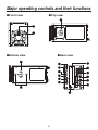
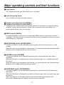
Major operating controls and their functions
Front view
Top view
Bottom view
Rear view
--
Major operating controls and their functions
Lens mount
2/3˝ standard bayonet type (B4 mount) lens is installed.
Lens fixing ring knob
Lens is fixed by turning the knob clockwise.
Camera mounting hole (1/4-20UNC)
Camera mounting hole (3/8-16UNC)
The screw holes can be used to secure the camera for installing it on camera housing,
and when using a pan/tilt head or a tripod. The screw holes are 10 mm deep. Use
screws which are less than 10 mm long.
MENU switch [MENU]
A menu will appear on the monitor screen when MENU switch is pressed for at least
3 seconds. The menu screen is cleared when the switch is pressed for at least 3 seconds
while the menu is displayed.
ENTER/AWB switch [ENTER/AWB]
The item just below can be selected by pressing this switch while the menu is on the
screen.
When the menu is not displayed or the camera is in shooting mode, the automatic white
balance control (AWB) can be set with this switch.
UP/ABB switch [UP/ABB]
The item just above can be selected by pressing this switch while the main menu is
displayed.
While the Sub menu is displayed, any setting can be brought up to a higher value with
this switch.
When the menu is not displayed or the camera is in shooting mode, the automatic black
balance control (ABB) can be set with this switch.
DOWN/BAR switch [DOWN/BAR]
The item just below can be selected by pressing this switch while the Sub menu is on
the screen.
While the Sub menu is displayed, any setting can be brought down to a lower value with
this switch.
When the menu is not displayed, the color bar and the shooting conditions are
alternately indicated by pressing the switch for about 5 seconds.
--
Major operating controls and their functions
HD SDI output connector [HD SDI OUT]
HD SDI signal output is given by this line.
G/L input connector [G/L IN]
For gen-lock with the camera, the external sync signal (black burst) or tri-level sync
signal is supplied to this input connector.
Operate indicator
Green LED lamp lights to indicate that the specified DC 12 V power is supplied to the
interface connector .
Cooling fan
• Do not block or obstruct the ventilation during operation. It may otherwise cause
internal heating or fire.
• The life of this fan is approximately 30,000 hours (at room temp. 77 °F (25 °C)).
Replace the fan as needed.
(When the room temperature is higher than 95 °F (35 °C), replace the fan 30 %
earlier.)
Be sure to ask the dealer for the replacement.
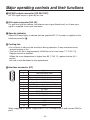
Interface connector [I/F]
Pin No.
1
2
3
4
5
6
7
8
9
10
11
12
13
14
15
Signal
Gen-lock signal GND
Not used
Not used
TX_N (EIA422)/TXD (EIA232) output
RX_N (EIA422)/RXD (EIA232) input
DC power supply input (+12 V)
Gen-lock signal input
DC GND
TX_P (EIA422) output
RX_P (EIA422) input
GND
Not used
GND
GND
GND
When supplying DC power, supply the DC +12 V voltage to pin 6 and connect GND to
pin 8.
- 10 -
Major operating controls and their functions
Use the multi-cable provided with the AK-HRP150G when supplying power from the
AK‑HRP150G.
Use the cable provided with the AW-PH650 when supplying power from the AW-PH650.
When supplying power from the AW-PH400, use the AW-CA15H29G or the
AW‑CAK4H1G cable kit depending on the configuration of the control system.
Use the AW-CA15H29G when supplying power from the AW-PH405.
When supplying power separately, ensure that the specifications of the interface cable
given below are satisfied.
Interface cable specifications
Use a cable with a performance equivalent or superior to the specifications given below.
AK-HC1800N
(High-density D-sub 15-pin connector)
G/L GND
DC GND
GND
DC power supply input
(+12 V)
DC power supply input
(+12 V)
Cable length: 5 m or less
Not used
Power input: +12 V ±10 %,
5 A or more
Not used
G/L GND
G/L signal input
G/L signal input
Not used
GND
DC GND
TX_N(EIA422)/
TXD(EIA232C) output
GND
GND
TX_P(EIA422) output
RX_N(EIA422)/
RXD(EIA232C) input
RX_N(EIA422)/
RXD(EIA232C) input
RX_P(EIA422) input
GND
TX_N(EIA422)/
TXD(EIA232C) output
RX_P(EIA422) input
TX_P(EIA422) output
Use a twisted-pair cable.
Connector:DHW10-153F200
made by Advanced Connectek Inc.
Cover:DE-C8-J9-F5-1R
made by Japan Aviation Electronics Industry, Ltd.
- 11 -
Major operating controls and their functions
Tally output connector [TALLY OUT]
The R tally and G tally signals are output from this connector.
Pin No.
1
2
3
4
Signal
GND
R_TALLY_OUT
G_TALLY_OUT
+12 V (500 mA Max)
IRIS connector [IRIS]
Used to connect the IRIS control cables of the lens.
Pin No.
1
2
3
4
5
6
Signal
Return control
VTR-S/S
UNREG GND
Iris manual selection
Iris control
UNREG 12 V
Pin No.
Signal
7
Iris follow
8
Iris auto selection
9
—
10
Zoom position information
11
Focus position information
12
NC
Zoom/Focus connector [ZOOM/FOCUS]
Used to connect the zoom/focus control cables of lens.
Pin No.
1
2
3
4
5
6
Signal
Focus control selection
Zoom control selection
GND
Forcible iris closing
Iris control
+Voltage
Pin No.
7
8
9
10
11
12
Signal
COM
Focus control
Zoom control
Iris control selection
COM +Voltage
COM –Voltage
Optional card slot
Slot for inserting an optional card.
Note
This product does not support the optional boards (AK-HHD1500G and
AK‑HDC1500G).
- 12 -
How to install
Be sure to ask the dealer for the installation,
adjustment and connection of this equipment.
How to set the lens
Standard 2/3˝ bayonet type (B4 mount) lens of any makers can be used*.
Turn the lens fixing ring knob counterclockwise to remove the lens mount cap.
Set the lens in place, and turn the lens fixing ring knob clockwise to precisely fix the
lens.
Connect the iris control cable to the IRIS connector.
Connect the zoom/focus control cable to the ZOOM/FOCUS connector.
* Note that there are some lenses uncontrollable with respect to zoom, focus function.
Iris control cable
(to IRIS connector)
Zoom/focus control cable
(to ZOOM/FOCUS connector)
(When a pan/tilt head is
used, connect the cable
to the pan/tilt head.)
Attach the provided filter to the iris
control cable and zoom/focus control
cable.
Lens fixing ring
knob
Filter
How to install on the camera housing, pan/tilt head, tripod, etc.
Precisely set the camera on the camera housing, pan/tilt head, tripod, etc. by using
the camera set-screw hole (1/4-20UNC, 3/8-16UNC).
When mounting the camera on a pan/tilt head, be sure to use proper tools and make
sure that there is no fear of falling off.
- 13 -
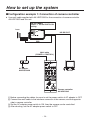
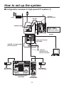
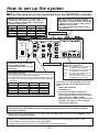
How to set up the system
Configuration example 1: Connection of camera controller
Use multi cable supplied with AK-HRP150G for the connection of camera controller
AK-HRP150G and this unit.
AK-HC1800N
Select “1” as the PROTOCOL
setting.
Lens
HD SDI OUT
IRIS
Multi cable
(POWER + CONTROL)
AC adapter
AW-PS510AN
Monitor
Camera controller
AK-HRP150G
Before connecting the cables, be sure to set the power switch of AC adapter to OFF.
Connect the multi cable to the interface connector of the camera, and the opposite
side to camera controller.
Set the AC adapter power switch to ON, then the camera can be controlled.
After shooting, set the AC adapter power switch to OFF.
- 14 -
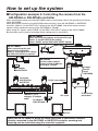
How to set up the system
Configuration example 2: High-speed P/T system (1)
IRIS
Cable kit
AW-CAK4H1G
Lens
HD SDI
ZOOM/FOCUS
AK-HC1800N
Select “1” as the
PROTOCOL setting.
HD SDI
Indoor pan/tilt head
AW-PH400
10BASE-T straight cable
(Pan/tilt control)
Cable kit
AW-CAK4H1G
(Camera control)
Monitor
AC adapter
AW-PS510AN
AC adapter
AW-PS510AN
Pan/tilt control panel
AW-RP400
Camera
controller
AK-HRP150G
- 15 -
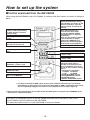
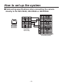
How to set up the system
Configuration example 3: High-speed P/T system (2)
Set and check the communication protocol and video format prior to installation.
When mounting the camera on the AW-PH400 pan/tilt head and controlling it from the AW-CB400
remote operation panel, select “4” as the PROTOCOL setting of the AK-HC1800N.
When connecting it directly to and controlling it from the AW-CB400, select “3” as the PROTOCOL setting.
HD SDI
IRIS
Camera connecting cable
AW-CA15H29G
Motor drive lens
ZOOM/FOCUS
AK-HC1800N
When mounting the camera
on the pan/tilt head:
Select “4” as the PROTOCOL
setting.
HD SDI
10BASE-T straight
cable (Pan/tilt +
camera control)
AC adapter
AW-PS510AN
Monitor
Monitor
Indoor
pan/tilt head
AW-PH400
Motor drive lens
HD SDI
AK-HC1800N
When connecting the camera
directly to the AW-CB400: Select
“3” as the PROTOCOL setting.
AC adapter
AW-PS510AN
Pan/tilt control panel
AW-RP400
Remote
operation panel
AW-CB400
- 16 -
How to set up the system
Configuration example 4: Controlling the camera from the
AW-RP655 or AW-RP555 controller
When installing the camera on the AW-PH650 outdoor pan/tilt head, refer to the operating instructions
of the AW-PH650.
When placing the camera on the AW-PH650 and controlling it from the AW-RP655 or AW-RP555
controller, select “4” as the PROTOCOL setting of the AK-HC1800N, and set the camera control
selector switch inside the housing of the AW-PH650 to “CB400.”
When using G/L signals, select “DSUB” as the GEN-LOCK INPUT setting of the AK-HC1800N.
Be absolutely sure to perform and check these settings prior to installation.
AK-HC1800N
When mounting the camera on the pan/tilt head:
Select “4” as the PROTOCOL setting.
Select “DSUB” as the GEN-LOCK INPUT setting.
AK-HC1800N
When connecting this unit
directly to the controller:
Select “3” as the PROTOCOL setting.
Set GEN-LOCK INPUT as required.
AW-PH650
Set the camera control
selector switch inside the
housing to “CB400”.
MULTI
SDI
OUT POWER
AC adapter
AW-PS510AN
Controller
AW-RP655 or
AW-RP555
Outdoor
pan/tilt
head
AW-PH650
RJ-45 relay adapter
10BASE-T (UTP
category 5) straight
cable
AC adapter
AW-PS510AN
G/L input
Monitor
To be locally
purchased
Monitor
When the AK-HC1800N, to which the motor drive lens is connected, has been
directly connected to the AW-RP655 or AW-RP555 controller, zooming and
focusing can be controlled using the controller’s joystick.
- 17 -
How to set up the system
Control exercised from the AW-CB400
When using the AW-CB400 for the AK-HC1800N, its switches and dials function as shown in the figure
below.
For switching the GAIN/PED
display and controller setting
menu display. For details on the
camera’s functions, open the
camera’s menu and select the
settings.
For capturing the camera
statuses, and synchronizing
the data. (Statuses of panel
switches only)
When these switches are
pressed while their lamps
are off, the PRESET, USER1
and USER2 files are opened,
respectively.
When any one of these switches
is pressed while its lamp is
lighted, the CURRENT file is
opened. The switch lamp lights
while the file is being opened.
For setting DTL to either ON
or OFF.
For selecting GAIN L, M, H or S1.
• S2 and S3 cannot be set.
For executing AWB.*1
For switching between CAM or
BAR.
For executing ABB.*1
For controlling R/B GAIN.
(–150 to +150)
For controlling R/B PED.
(–100 to +100)
These are the OPTION switches,
and each switch makes it
possible to control one of the
items listed below. (The items
are set on the controller setting
menu.)
• Camera menu operations
A: MENU B: ENTER
C: UP
D: DOWN
• ZOOM TELE/WIDE control
• FOCUS NEAR/FAR control
• ND FILTER control
• DIGITAL EXTENDER control
For controlling the MASTER
PEDESTAL. (−150 to +150)
For controlling IRIS AUTO,
MANU and LOCK.
For controlling the iris when
IRIS is set to MANUAL.
*1: The lamp of the ABB or AWB switch flashes while automatic white balance or automatic
black balance is being executed, respectively. When ABB or AWB is completed successfully,
the corresponding lamp goes off; when it is not completed successfully, it lights up.
When changing the panel display for use with the AK-HC1800N, please use panel sheet VGKB0008 (sold
separately as a replacement part).
Ver.2.00 or a subsequent version of the AW-CB400 software must be installed in order for the
AK‑HC1800N to be controlled using the AW-CB400.
To check the software version of your AW-CB400, contact your dealer.
- 18 -
How to set up the system
When the camera is to be controlled from the AW-RP655 controller
When the LCD is in the gain adjustment mode
Select the desired gain setting from GAIN SELECT
LOW to S.GAIN3.
When the LCD is in the pedestal adjustment mode
Adjust the M PEDESTAL setting (–150 to +150).
When the camera menu mode is established
Perform the camera menu operations.
Each time the MODE button is pressed, the
setting is switched between CAM and BAR.
The MODE button lights up at the BAR setting.
For executing AWB.*1
For executing ABB.*1
Switch between gain adjustment
mode and pedestal adjustment mode.
When the LCD panel is in the gain adjustment mode
Adjust the R GAIN setting (–150 to +150).
When the LCD panel is in the pedestal adjustment mode
Adjust the R PEDESTAL setting (–100 to +100).
When the LCD panel is in the gain adjustment mode
Adjust the B GAIN setting (–150 to +150).
When the LCD panel is in the pedestal adjustment mode
Adjust the B PEDESTAL setting (–100 to +100).
*1: The lamp of the ABB or AWB switch flashes while
automatic white balance or automatic black balance
is being executed, respectively. When ABB or AWB is
completed successfully, the corresponding lamp goes
off; when it is not completed successfully, it lights up.
In the case of the AK-HC1800N camera, the
following buttons on the AW-RP655 will not
work.
• WHITE BAL A/B/ATW
• GAIN AUTO/MANU
• DATA SET
When the AK-HC1800N, to which the motor drive lens is connected, has been directly
connected to the AW-RP655 controller, zooming and focusing can be controlled using the
controller’s joystick.
When changing the panel display for use with the AK-HC1800N, please use panel sheet VGKB0007 (sold
separately as a replacement part).
Procedure for camera menu operation (AW-RP655)
1Press the MENU button to set the LCD panel display to the menu mode.
2Turn the jog dial (main) to select CAMERA SETTING.
3Press the OK button.
4The right display appears on the LCD panel:
When the OK button is pressed again, the menu of the AK-HC1800N appears on the
monitor.
5Turn the jog dial (main) to modify menu items of the AK-HC1800N and change the
data. When changing the data, the data settings are decremented by turning the dial
clockwise and incremented by turning it counterclockwise. Push the jog dial (main) down
to enter the settings.
6To exit the camera menu, press the MENU button or R/B GAIN/PED button.
Ver.0010 or a subsequent version of the AW-RP655 software must be installed in order for the
AK‑HC1800N to be controlled using the AW-RP655.
To check the software version of your AW-RP655, contact your dealer.
- 19 -
How to set up the system
When the camera is to be controlled from the AW-RP555 controller
When these buttons are pressed while
their LEDs are off, the PRESET, USER1 and
USER2 files are opened respectively. When
a button is pressed while its LED is lit, the
CURRENT file is opened.
The LED of a button blinks while its file is
being opened.
Each time the GAIN button is pressed, the setting
is switched in the sequence of LOW MID
HIGH S.GAIN1, and the mode is displayed by
the LEDs as shown below.
LOW
MID
HIGH
S.GAIN1
GAIN button MANU L LED MANU H LED
OFF
OFF
OFF
OFF
ON
OFF
OFF
OFF
ON
ON
OFF
OFF
Each time the MODE button is
pressed, the setting is switched
between CAM and BAR.
The MODE button lights up at the
BAR setting.
For executing AWB.*1
For executing ABB.*1
Shutter mode selection
Each time this button is pressed, one of the shutter modes set
by the controller or “shutter OFF” is selected.
The SHUTTER button lights up in all modes except shutter OFF.
The shutter mode settings established by the PRESET buttons
are as follows.
MODE
1/100
1/120
1/250
1/500
1/1000
PRESET No.
PRESET1
PRESET2
PRESET3
PRESET4
PRESET5
MODE
1/2000
--SYNCHRO
--OFF
PRESET No.
PRESET6
PRESET7
PRESET8
PRESET9
PRESET10
Use these buttons to perform the
camera menu operations.
MENU:This operates in the same way
as MENU on the camera.
ITEM:This operates in the same way
as ENTER on the camera.
YES:This operates in the same way
as UP on the camera.
NO:This operates in the same way
as DOWN on the camera.
In the case of the AK-HC1800N camera, the
following buttons on the AW-RP555 will not
work.
• WHITE BAL A/B/ATW
• SCENE FILE 3
*1: The lamp of the ABB or AWB switch
flashes while automatic white balance or
automatic black balance is being executed,
respectively. When ABB or AWB is
completed successfully, the corresponding
lamp goes off; when it is not completed
successfully, it lights up.
When the AK-HC1800N, to which the motor drive lens is connected, has been directly
connected to the AW-RP555 controller, zooming and focusing can be controlled using the
controller’s joystick.
When changing the panel display for use with the AK-HC1800N, please use panel sheet VGKB0006 (sold
separately as a replacement part).
Ver.041 or a subsequent version of the AW-RP555 software must be installed in order for the
AK‑HC1800N to be controlled using the AW-RP555.
To check the software version of your AW-RP555, contact your dealer.
- 20 -
How to set up the system
Cable wiring specifications when connecting the camera
directly to the AW-CB400, AW-RP655 or AW-RP555
AW-CB400
AW-RP655
AW-RP555
Modular
connector
8-pin plug
High-density D-Sub 15-pin
connector (male)
- 21 -
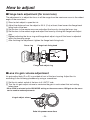
Operation procedure
1
2
3
5
Turn
on the power of each
equipment.
This adjustment is needed when the
camera is used for the first time or
after leaving unused for a long time.
The adjustment is necessary when
the ambient temperature is greatly
changed or at the change of season.
After adjusting the black balance
once, re-adjustment is not needed
under the same condition.
Properly
adjust the light for the
object.
Adjust
the flange back of the lens,
the iris and the focus.
6
Flange back must be adjusted when
the camera is used for the first time
or after replacement of the lens.
4
Adjust the black balance.
Start shooting.
(After shooting, be sure to turn off the
power of each equipment connected.)
Adjust the white balance.
This adjustment is needed when the
camera is used for the first time or
after leaving unused for a long time.
The adjustment is necessary when
the lighting condition or brightness is
changed.
After adjusting the white balance
once, re-adjustment is not needed
under the same condition.
- 22 -
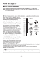
How to adjust
Flange back adjustment (for zoom lens)
The adjustment is to adjust the focus in all the range from the maximum zoom to the widest
angle of the zoom lens.
Shoot a dark object to open the iris.
Adjust the distance from the object to 6.6 ft. (2 m) at least, then loosen the flange back
fixing knob of the lens.
Set the lens to the maximum zoom and adjust the focus by turning the focus ring.
Set the lens to the widest angle and adjust the focus by turning the flange back adjust
ring.
Repeat adjusting the focus ring and flange back adjust ring until the focus is adjusted
within the zooming range.
After finishing the adjustment, tighten the flange back fixing knob.
Focus ring
Flange back fixing knob
Flange back adjust ring
Lens iris gain volume adjustment
Iris gain adjust hole (G or S) is provided at front of the lens housing. Adjust the iris
according to the following procedure by using a screwdriver.
Set the iris select switch of the lens to A “AUTO” side.
Turn the iris gain adjust volume to maximize the gain in such extent that no hunting
takes place.
* When CAM is selected as the IRIS MODE setting on the camera menu, IRIS gain on the menu
can be used to make adjustments.
Iris gain adjust volume
Auto iris power zoom lens
- 23 -
How to adjust
White balance adjustment
Adjust the white balance after shooting a white object by at least 50 % of the screen.
Note: If the white signal level is over 100 % or less than 50 %, the white balance may not
be normally adjusted.
Color temperature and white balance adjustment (reference)
When carbon is burnt, it develops various
Blue sky
colors of light depending on the temperature.
Natural light can be specified by color
Rainy
temperature reflecting to the color developed
when carbon is burnt.
Cloudy
AWC
The light of 3,200K (K=Kelvin, –273 °C equals
Partly cloudy
to absolute zero temperature 0K) represents
the same value (color) as what develops
Fine
when carbon is burnt at 3,200K (2,927 °C).
The relationship between the color
Fluorescent lamp
temperature of the light source and weather
condition is indicated in the right figure. Let’s
Halogen lamp
study the difference of shooting an indoor
Tangsten lamp
object from shooting one outdoors. Studios
are usually lighted with incandescent lamps
and the color temperature of a white object in
a studio is around 3,000K. The color
Candle
temperature of a white object outdoors is
around 6,500K. The former may look a little
yellowish while the latter appears somewhat
bluish when they are shot by a camera.
However, the human eye does not recognize
color differences among these objects even
under different ambient lighting conditions,
because of their adaptability to light.
The video camera reproduces color differences with high fidelity and the color of an object
somewhat different from what appears to the human eye.
Therefore, there is a need to adjust the white balance in order to correct differences
between color temperatures.
Note
Color temperature outdoors may vary depending on weather conditions.
- 24 -
How to adjust
Black balance adjustment
Adjust it with the lens closed.
When the motor drive lens is controlled from the camera, adjusting the black balance
causes the lens to be automatically closed.
Gen-lock adjustment
When multiple cameras are used or the camera is combined with other equipment, it is
necessary to adjust the phase for phase matching by external synchronization.
Horizontal phase adjustment
Observe the waveforms of externally synchronizing signal input (black burst signal) and
video signal output by a two-phenomenon oscilloscope, and make the horizontal phase
according to the camera menu.
Adjustment with GEN-LOCK of SETTING menu
When HD synchronizing signals are input:
Roughly adjust the synchronizing signal input and video signal output phases by
H PHASE-COARSE.
Finely adjust the synchronizing signal input and video signal output phases by
H PHASE-FINE.
When SD synchronizing signals are input:
Roughly adjust the synchronizing signal input and video signal output phases by
SD-HD PHASE CRS.
Finely adjust the synchronizing signal input and video signal output phases by
SD-HD PHASE FINE. If the adjustment performed using SD-HD PHASE is not
satisfactory, use H PHASE-COARSE/FINE.
- 25 -
Intelligent functions
When using the camera in outdoor environments, the brightness and color temperature will
differ significantly as the day progresses from the morning to the afternoon, to the evening
to night. The camera’s intelligent functions serve to automatically correct the video level
and color temperature to compensate for the changes taking place outdoors.
In outdoor environments, the brightness changes significantly, by a factor of 10 to the
power of 6, from 0.01 lux under a crescent moon to 10,000 lux under a clear sky.
Similarly, there is a considerable change of 5000K in the color temperature from 3000K
after sunrise to 8000K under a clear, bright sky.
In the past, the gain, lens iris, ND filter, and minus gain were supported as video levels
adjustments, whereas manual gain adjustments and manual CC filter settings were
supported as color temperature adjustments.
However, the problem with the user having to make these adjustments manually each
time was that there was not enough time to select the optimum adjustments when a
sudden emergency situation such as an earthquake arose, with the result that shooting
opportunities were lost.
Now, using the intelligent functions, this kind of problem has been solved.
Automatic video level
adjustment method
• Clear sky
• Cloudy sky
Automatic color temperature
adjustment method
Minus gain setting variable
ND filter setting variable
• Bright, cloudy sky
• Evening
• Cloudy sky
Lens iris adjustment
• Moonlight
Brightness
(lux)
• Crescent
moon
Type of light
condition
5600 ON, RB
gain adjustment
• Daylight
fluorescent light
• Midday
• 2 hours after
sunrise
Gain setting variable
• 1 hour after
sunrise
Color
Type of light
temperature condition
(K) of light
- 26 -
5600 OFF, RB
gain adjustment
Intelligent functions
Automatic video level adjustment method:
The video level is automatically adjusted by controlling the lens iris, gain
(including pixel addition and frame addition), ND filter setting, and minus gain.
Automatic color temperature adjustment method:
The color temperature is automatically adjusted by controlling the R and B
gain levels from the D5600K OFF or ON setting.
The intelligent functions are set using the INTELLIGENT1, INTELLIGENT2, and
INTELLIGENT SET menus accessed from the SETTING menu.
Notes
The intelligent functions are valid with the VIDEO MENU only; MANUAL (functions
OFF) is the fixed setting with the FILM MENU.
The INTELLIGENT menus are not displayed, either.
The conditions established by the intelligent functions may differ depending on
the camera settings, and optimal settings may not be selected even when filming
under the same brightness and color temperature conditions.
When V MIX or FRAME MIX is switched to ON or OFF during an AGC operation,
shock noise accompanying the switching will be heard.
When ON or SYNCHRO has been selected as the shutter setting, hunting may
occur when FRAME MIX switches to ON or OFF.
The color temperature may not be tracked properly under special shooting
conditions such as backlight, reflected light, or sunset.
- 27 -
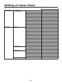
Setting of menu items
How to display the menus
Two methods are used to display the menus.
Using AK-HC1800N multi purpose camera to display the menus:
Hold down the MENU switch on the rear panel of the main unit for at least 3 seconds
to display the TOP menu.
Use the UP/DOWN switch to move the cursor to the target item, and press the
ENTER switch to move to a menu at a lower hierarchical level.
Using AK-HRP150G camera controller
Press the MENU ON/OFF switch on the AK-HRP150G so that its lamp lights.
The TOP menu now appears.
Move the cursor to the target item, and press the MENU switch to move to a menu at
a lower hierarchical level.
TOP menu
When the VIDEO MENU is selected:
When the FILM MENU is selected:
- 28 -
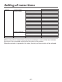
Setting of menu items
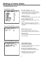
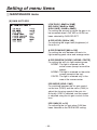
MAINTENANCE menu
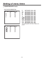
[1] BLACK SHADING
DETECTION
For automatically correcting the black
shading.
CORRECT(DIG) [OFF, ON]
For ON/OFF control of the detection
correction.
- 29 -
Setting of menu items
MAINTENANCE menu
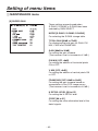
[2] PEDESTAL, GAMMA
M PEDESTAL [–200 to +200]
For adjusting the black level.
R PEDESTAL [–100 to +100]
For correcting the red in relation to the
master pedestal.
B PEDESTAL [–100 to +100]
For correcting the blue in relation to the
master pedestal.
When the AK-HRP150G has been
connected, M PEDESTAL, R PEDESTAL and
B PEDESTAL operations cannot be
performed using the menu.
M GAMMA
[0.30 to 0.75 (DRS OFF), –10 to +10 (DRS ON)]
For adjusting the gamma characteristics.
R GAMMA
[–15 to +15 (DRS OFF), –10 to +10 (DRS ON)]
For adjusting the gamma characteristics
of the red in relation to the master gamma
characteristics.
B GAMMA
[–15 to +15 (DRS OFF), –10 to +10 (DRS ON)]
For adjusting the gamma characteristics of
the blue in relation to the master gamma
characteristics.
M BLACK GAMMA [–32 to +32]
For adjusting the gamma characteristics in
the vicinity of the black.
R BLACK GAMMA [–15 to +15]
For adjusting the gamma characteristics of
the red in the vicinity of the black in relation
to the master gamma characteristics.
- 30 -
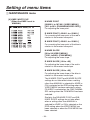
Setting of menu items
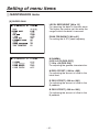
MAINTENANCE menu
[2] PEDESTAL, GAMMA
B BLACK GAMMA [–15 to +15]
For adjusting the gamma characteristics of
the blue in the vicinity of the black in relation
to the master gamma characteristics.
GAMMA [OFF, ON]
For turning the gamma correction ON or OFF.
BLACK GAMMA [OFF, ON]
For turning the black gamma correction ON
or OFF.
When ON has been selected as the DRS
setting, the BLACK GAMMA setting does not
take effect.
When the VIDEO MENU is selected:
EFFECT DEPTH [1 to 5]
For selecting the effects of the contrast
adjustment when ON has been set for DRS.
DRS [OFF, ON]
For adjusting the contrast automatically when
this is set to ON.
When the FILM MENU is selected:
CINE GAMMA SELECT
[VIDEO REC, FILM REC]
For selecting either the film-use or video-use
cine gamma characteristics.
BLACK STR. LEVEL [00% to 30%]
For setting the BLACK STRETCH position.
DYNAMIC LEVEL [200% to 500%]
For setting the dynamic range.
- 31 -
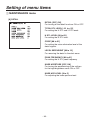
Setting of menu items
MAINTENANCE menu
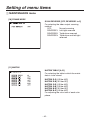
[3] FLARE
R FLARE [000 to 100]
G FLARE [000 to 100]
B FLARE [000 to 100]
For adjusting the flare correction.
FLARE [OFF, ON]
For turning the flare correction ON or OFF.
- 32 -
Setting of menu items
MAINTENANCE menu
[4] KNEE, WHITE CLIP
(When the KNEE is set to
MANUAL)
M KNEE POINT
[080.00% to 107.00% (VIDEO MENU)]
[30% to 90% (FILM MENU/VIDEO REC)]
For adjusting the knee point.
R KNEE POINT [–25.00% to +25.00%]
For correcting the knee point of the red in
relation to the master knee point.
B KNEE POINT [–25.00% to +25.00%]
For correcting the knee point of the blue in
relation to the master knee point.
M KNEE SLOPE
[00 to 99 (VIDEO MENU)]
[150% to 600% (FILM MENU)]
For adjusting the knee slope.
R KNEE SLOPE [–99 to +99]
For adjusting the knee slope of the red in
relation to the master knee slope.
B KNEE SLOPE [–99 to +99]
For adjusting the knee slope of the blue in
relation to the master knee slope.
The M KNEE POINT and M KNEE SLOPE
settings do not take effect when a setting
other than MANUAL is selected for KNEE or
ON is selected as the DRS setting when the
VIDEO MENU has been selected or when
FILM REC is selected as the CINE GAMMA
SEL setting when the FILM MENU has been
selected.
Similarly, the R/B KNEE POINT and R/B
KNEE SLOPE settings do not take effect
when a setting other than MANUAL is
selected for KNEE or ON is selected as the
DRS setting when the VIDEO MENU has
been selected or when the FILM MENU has
been selected.
- 33 -
Setting of menu items
MAINTENANCE menu
[4] KNEE, WHITE CLIP
(When the KNEE is set to
AUTO)
A. KNEE POINT [080.00% to 107.00%]
For setting the auto knee break point position.
This setting does not take effect when a
setting other than AUTO is selected for KNEE
or ON is selected as the DRS setting when
the VIDEO MENU has been selected or when
the FILM MENU has been selected.
A. KNEE LEVEL [100% to 109%]
For setting the maximum level of auto knee.
This setting does not take effect when a
setting other than AUTO is selected for KNEE
or ON is selected as the DRS setting when
the VIDEO MENU has been selected or when
the FILM MENU has been selected.
M WHITE CLIP LVL [090% to 109%]
For setting the white clip level.
R WHITE CLIP LVL [–15% to +15%]
For correcting the amount of red for the
M WHITE CLIP LVL.
B WHITE CLIP LVL [–15% to +15%]
For correcting the amount of blue for the
M WHITE CLIP LVL.
- 34 -
Setting of menu items
MAINTENANCE menu
[4] KNEE, WHITE CLIP
KNEE [OFF, MANUAL, AUTO]
For selecting the knee operation mode.
This setting does not take effect when FILM
REC is selected or DRS is ON.
WHITE CLIP [OFF, ON]
For tuning white clip ON or OFF.
HIGH COLOR [OFF, ON]
For improving the color reproducibility of the
high-brightness areas when it is set to ON.
This setting does not take effect when a
setting other than MANUAL is selected for
KNEE or ON is selected as the DRS setting
when the VIDEO MENU has been selected
or when the FILM MENU has been selected.
[5] R/B GAIN
R GAIN [–200 to +200]
For adjusting the gain of the red.
B GAIN [–200 to +200]
For adjusting the gain of the blue.
ND FILTER [CLEAR, 1/4, 1/16, 1/64]
For selecting the ND filter setting.
When the AK-HRP150G has been
connected, the items on this page cannot be
operated using the menu.
- 35 -
Setting of menu items
MAINTENANCE menu
[6] DETAIL
DETAIL [OFF, ON]
For turning all the detail functions ON or OFF.
TOTAL DTL LEVEL [–31 to +31]
For setting the H DTL and V DTL levels.
H DTL LEVEL [00 to 63]
For setting the H DTL level.
CRISP [00 to 31]
For setting the noise elimination level of the
detail signals.
LEVEL DEPENDENT [00 to 15]
For removing the detail in the dark areas.
PEAK FREQUENCY [00 to 31]
For setting the H DTL peak frequency.
KNEE APERTURE [OFF, ON]
For turning the emphasizing of the outlines
for the high-brightness areas ON or OFF.
KNEE APE LEVEL [0 to 5]
For adjusting the knee aperture level.
- 36 -
Setting of menu items
MAINTENANCE menu
[6] DETAIL
SLIM DETAIL [OFF, ON]
For setting the detail more finely at ON.
DETAIL(+) [–31 to +31]
For adjusting the detail gain in the + direction.
DETAIL(–) [–31 to +31]
For adjusting the detail gain in the – direction.
DETAIL CLIP [00 to +63]
For minimizing the glare caused by adding
too much detail as a result of a detail clip
adjustment.
DETAIL SOURCE
[(G+R)/2, (G+B)/2, (2G+B+R)/4, (3G+B)/4,
R, G]
For setting the ratio of the RGB signal
components which create the detail.
- 37 -
Setting of menu items
MAINTENANCE menu
[7] SKIN TONE DETAIL
SKIN TONE DTL [OFF, ON]
For turning the SKIN TONE DTL ON or OFF.
SKIN GET [OFF, ON]
When ON is selected, the box cursor is
output to the screen center. When the image
of the subject’s skin is placed inside the
box cursor and the ENTER operation is
performed,
I CENTER and Q PHASE are set
automatically.
SKIN DTL CORING [0 to 7]
For setting the SKIN TONE DTL coring
amount.
Y MAX [000 to 255]
For setting the upper limit of the brightness in
the skin tone specification area.
Y MIN [000 to 255]
For setting the lower limit of the brightness in
the skin tone specification area.
I CENTER [000 to 255]
For setting the phase of the I axis in the skin
tone specification area.
I WIDTH [000 to 255]
For setting the phase width of the I axis in the
skin tone specification area.
Q WIDTH [000 to 255]
For setting the phase range of the Q axis in
the skin tone specification area.
Q PHASE [–128 to +127]
For setting the phase of the Q axis in the skin
tone specification area.
- 38 -
Setting of menu items
MAINTENANCE menu
[8] GAIN, AUTO IRIS
LOW GAIN [–06dB to 30dB]
MID GAIN [–06dB to 30dB]
HIGH GAIN [–06dB to 30dB]
For setting the amount by which the gain is to
be increased when LOW, MID or HIGH has
been selected by GAIN SELECT.
A.IRIS LEVEL [000 to 100]
For adjusting the target level (brightness) of
the auto iris.
A.IRIS PEAK/AVE [000 to 100]
For setting the ratio between the auto iris
light-metering peak value and average value.
A.IRIS WINDOW [NORM1, NORM2, CENTR]
For setting the auto iris light-metering area.
NORM1:The light is metered on the
entire screen (except around the
edges).
NORM2:The light is metered on the entire
screen (except at the top).
CENTR:The light is metered only in the
area at the screen center.
IRIS MODE [LENS, CAM]
For switching between the iris gain control
on the lens (LENS) and the menu (CAM) to
adjust the focusing speed of the auto iris.
Normally, LENS is selected, and the speed
is adjusted using the iris gain control on the
lens.
IRIS GAIN [01 to 10]
For adjusting the iris gain when CAM has
been selected as the IRIS MODE setting.
- 39 -
Setting of menu items
MAINTENANCE menu
[9] SUPER GAIN
These settings are performed when
S.GAIN1, S.GAIN2 or S.GAIN3 has been
selected by GAIN SELECT.
MODE [S.GAIN1, S.GAIN2, S.GAIN3]
For selecting the S.GAIN storage table.
TOTAL GAIN [00dB to 72dB]
For displaying the total gain for GAIN, PIX
MIX, V MIX and FRAME MIX.
GAIN [00dB to 36dB]
For setting the gain increase.
(The increase is set in increments of 3 dB.)
PIX MIX [OFF, +6dB]
For setting the addition of horizontal pixels
ON or OFF.
V MIX [OFF, +6dB]
For setting the addition of vertical pixels ON
or OFF.
FRAME MIX [OFF, 06dB to 24dB]
For setting the gain increase based on
accumulation in the CCD image sensor.
(The increase is set in increments of 6 dB.)
H DETAIL LEVEL [00 to 63]
For setting the H DETAIL level.
CRISP [00 to 31]
For setting the noise elimination level of the
detail signals.
- 40 -
Setting of menu items
MAINTENANCE menu
[9] SUPER GAIN
LEVEL DEPENDENT [00 to 15]
For removing the detail in the dark areas.
The higher the number set, the wider the
range in which the detail is removed.
PEAK FREQUENCY [00 to 31]
For setting the H DTL peak frequency.
M GAMMA
[0.35 to 0.75 (DRS OFF)]
[–10 to +10 (DRS ON)]
For adjusting the gamma characteristics.
M PED OFFSET [–200 to +200]
For adjusting the amount of offset in the
black level.
R PED OFFSET [–200 to +200]
For adjusting the amount of offset in the
R pedestal.
B PED OFFSET [–200 to +200]
For adjusting the amount of offset in the
B pedestal.
- 41 -
Setting of menu items
MAINTENANCE menu
[10] FRAME MODE
SCAN REVERSE [OFF, REVERSE1 to 3]
For selecting the video output scanning
method.
OFF:
Normal scanning
REVERSE1: Left/right reversed
REVERSE2: Top/bottom reversed
REVERSE3:Top/bottom and left/right
reversed
[11] MATRIX
MATRIX TABLE [A, B]
For selecting the table in which the matrix
data is to be stored.
MATRIX R-G [–31 to +31]
MATRIX R-B [–31 to +31]
MATRIX G-R [–31 to +31]
MATRIX G-B [–31 to +31]
MATRIX B-R [–31 to +31]
MATRIX B-G [–31 to +31]
For adjusting the color tone of each color
phase.
- 42 -
Setting of menu items
MAINTENANCE menu
[12] COLOR CORRECTION
R
SAT/PHASE [–63 to +63]
Mg SAT/PHASE [–63 to +63]
B
SAT/PHASE [–63 to +63]
Cy SAT/PHASE [–63 to +63]
G
SAT/PHASE [–63 to +63]
Yl
SAT/PHASE [–63 to +63]
R-Mg SAT/PHASE [–63 to +63]
Mg-B SAT/PHASE [–63 to +63]
B-Cy SAT/PHASE [–63 to +63]
Cy-G SAT/PHASE [–63 to +63]
G-Yl SAT/PHASE [–63 to +63]
Yl-R SAT/PHASE [–63 to +63]
For adjusting the color tone of each color
phase.
- 43 -
Setting of menu items
2 SETTING menu
[1] MODE
When the VIDEO MENU is selected
D5600K [OFF, ON]
When the FILM MENU is selected
LIGHTING [TUNGSTEN, DAYLIGHT]
ON, DAYLIGHT:
The color temperature is corrected
electrically to attain white balance in
5600K-degree environments.
OFF, TUNGSTEN:
The color temperature is corrected
electrically to attain white balance in
3200K-degree environments.
GAIN SELECT
[LOW, MID, HIGH, S.GAIN1 to 3]
For selecting LOW, MID, HIGH, S.GAIN1,
S.GAIN2 or S.GAIN3 as the gain setting.
CAM ID [OFF, BAR, ON]
For selecting how the camera ID is to be
displayed.
OFF: The camera ID is not displayed.
BAR:The camera ID is displayed only in
the color bar mode.
ON:The camera ID is displayed at all
times.
- 44 -
Setting of menu items
2 SETTING menu
[1] MODE
CAM ID POSI [0 to 3]
For selecting where the camera ID is to be
displayed.
0: top left, 1: top right, 2: bottom left,
3: bottom right
MATRIX TABLE [OFF, A, B]
For selecting OFF, A or B as the matrix
setting.
COLOR CORRECTION [OFF, ON]
For turning the color correction function ON
or OFF.
Note
When DIGITAL EXTENDER is set to
X2, the resolution is downgraded.
The detail function ceases to work as
well.
DIGITAL EXTENDER [OFF, X2]
For digitally doubling the images when set to
X2.
BAR SEL
[FULL (16:9), FULL (4:3), SMPTE (16:9),
SMPTE (4:3), ARIB]
For selecting the color bars.
Select the 4:3 color bars for down-conversion
at the system side. The color bars and
characters will then be contained within the
4:3 picture angle.
- 45 -
Setting of menu items
2 SETTING menu
[1] MODE
FORMAT
For displaying the video output format.
(1080/59.94i)
STATUS [OFF, ON]
For turning the AWB/ABB operation displays
ON or OFF.
The status displays are as follows.
AWB ACTIVE:
While automatic white balance is being
executed.
AWB OK:
When the automatic white balance has
been adjusted satisfactorily.
OUT RANGE RB:
When the automatic white balance has
not been adjusted satisfactorily.
(“RB” denotes the colors which were
not balanced properly.)
HIGH LIGHT NG:
When the lighting is too high.
LOW LIGHT NG:
When the lighting is too low.
ABB ACTIVE:
While automatic black balance is being
executed.
IRIS CONTROL NG:
When the lens is open.
- 46 -
Setting of menu items
2 SETTING menu
[1] MODE
ABB OK:
When the automatic black balance has
been adjusted satisfactorily.
OUT RANGE RGB:
When the automatic black balance has
not been adjusted satisfactorily.
(“RGB” denotes the colors which were
not balanced properly.)
MENU ON BAR [OFF, ON]
For selecting whether the menu is to be
displayed with the color bars.
Switching from ON to OFF or vice versa is
not possible when color bars have been set.
MENU SEL [VIDEO MENU, FILM MENU]
For selecting the menu display.
FAN [OFF, AUTO, ON]
For selecting the operation mode of the
air-cooled fan.
OFF: The fan is always off.
AUTO:The fan is automatically controlled
by the temperature sensor.
ON: The fan is running at all times.
At the FAN OFF setting, ensure that
the product is operated in an ambient
temperature below 86 °F (30 °C).
- 47 -
Setting of menu items
2 SETTING menu
[2] SHUTTER
SHUTTER MODE [OFF, ON, SYNCHRO]
For selecting the operation mode of the
shutter.
OFF:
For turning the shutter OFF.
ON:For setting the shutter speed
which was set by SHUTTER
SPEED.
SYNCHRO:For setting the shutter speed
which was set by SYNCHRO
SCAN.
SHUTTER SPEED
[1/100, 1/120, 1/250, 1/500, 1/1000, 1/2000
(VIDEO MENU)]
[180.0 deg, 172.8 deg, 144.0 deg, 120.0 deg,
90.0 deg, 45.0 deg (FILM MENU)]
For setting the shutter speed at the
SHUTTER ON setting.
SYNCHRO SCAN
[60.32 Hz to 149.2 Hz]
[356.4 deg to 144.0 deg (FILM MENU)]
For setting the shutter speed in the synchro
scanning mode.
- 48 -
Setting of menu items
2 SETTING menu
[3] GEN-LOCK
GEN-LOCK INPUT [BNC, DSUB]
For selecting whether the sync signals are to
be input from the BNC or D-SUB connector.
H PHASE-COARSE
[–060 to +060]
For roughly adjusting the horizontal phase.
H PHASE-FINE [–045 to +045]
For finely adjusting the horizontal phase.
SD-HD PHASE CRS [–4 to +4]
For roughly adjusting the phase of the HD
video signals when SD sync signals have
been input.
SD-HD PHASE FINE [–99 to +99]
For finely adjusting the phase of the HD
video signals when SD sync signals have
been input.
- 49 -
Setting of menu items
2 SETTING menu
[4] PROTOCOL
PROTOCOL [1 to 4]
For selecting the remote control
communication system in accordance with
the system connected.
1:Information camera communication
protocol (EIA422)
For connecting the AK-HRP150G or
AK-HRP900
(With the AK-HRP900, this setting
cannot be used at a baud rate of
9600 bps.)
2:Information camera communication
protocol (EIA232)
For connecting a PC
(This setting cannot be used at a baud
rate of 9600 bps.)
3:Convertible PC control protocol
(EIA422)
For connecting the AW-CB400
(baud rate fixed at 9600 bps)
4:Convertible PC control protocol
(EIA232) For connecting the AW‑PH400
pan/tilt head (baud rate fixed at
9600 bps)
The protocol is actually switched after the
power has been turned off and back on.
- 50 -
Setting of menu items
2 SETTING menu
[5] INTELLIGENT1
M-GAIN [–6dB to 72dB]
The current gain total is displayed here.
ND-FIL [CLEAR, 1/4, 1/16, 1/64]
The current ND filter position is displayed
here.
INTELLIGENT
[MANUAL, AUTO, LOCK]
The operation mode for intelligent control is
set here.
AUTO:AGC and ATW are adjusted
automatically.
LOCK:The status of the AGC and
ATW adjustments is held as
soon as the INTELLIGENT
item setting is changed from
AUTO to LOCK.
MANUAL:Intelligent control is operated
using the settings selected
from the regular menus and
camera controller.
When AUTO or LOCK is set on the
INTELLIGENT1 menu, INTELLIGENT2 is
set to MANUAL.
Similarly, when AUTO or LOCK is
set on the INTELLIGENT2 menu,
INTELLIGENT1 is set to MANUAL.
The INTELLIGENT SET menu settings are
also switched in tandem.
- 51 -
Setting of menu items
2 SETTING menu
[5] INTELLIGENT1
When AUTO or LOCK has been set as the
operation mode, restrictions apply to the
settings of some of the other menus, as
indicated below.
AGC
•The auto iris function is operational
regardless of whether the auto iris
setting from the camera controller is ON
or OFF.
•The setting from the menu and camera
controller is not reflected for GAIN
SELECT on the SETTING menu.
•The LOW GAIN, MID GAIN, and HIGH
GAIN settings for GAIN/AUTO IRIS
on the MAINTENANCE menu are not
reflected.
•The S.GAIN settings (gain, detail,
gamma, and pedestal settings) on the
MAINTENANCE menu are not reflected.
•The ND FILTER setting for R/B GAIN
on the MAINTENANCE menu is not
reflected.
ATW
•R/B GAIN can be controlled from the
menu and camera controller, but the
white balance is automatically adjusted
if the subject is identified as being white.
•AWB is executed in a 25 % 25 %
area at the center regardless of the
ATW AREA setting.
However, what is determined to be the
ATW color temperature is not always
consistent with AWB, so the white
balance may be changed by ATW after
AWB has been executed.
- 52 -
Setting of menu items
2 SETTING menu
[5] INTELLIGENT1
INTELLIGENT MODE
[AGC, ATW, AGC+ATW]
The intelligent control setting is selected
using this menu item.
AGC:When the gain cannot be
adjusted within the IRIS
RANGE setting, gain control
(including PIX MIX, V MIX,
and FRAME MIX) and
automatic exposure control
performed by adjusting the
ND filter setting are executed.
ATW:When the subject is
identified as being white, the
white balance is adjusted
automatically.
AGC+ATW:The above AGC and ATW
adjustments are performed at
the same time.
ND FILTER SELECT
[CLEAR, 1/4, 1/16, 1/64, AUTO]
The ND filter setting during AGC operations
is selected using this menu item.
AUTO:Depending on the light quantity,
the ND filter is adjusted to the
appropriate position.
CLEAR, 1/4, 1/16, 1/64:
The specified ND filter setting is
fixed.
During AGC operations, control cannot be
exercised from the camera controller.
AGC SPEED [1 to 5]
The AGC convergence speed can be set to
any of 5 levels here.
The speed becomes faster as the figure
increases.
- 53 -
Setting of menu items
2 SETTING menu
[5] INTELLIGENT1
AGC GAIN STEP [NORMAL, MAX]
The AGC gain increment or decrement step
is selected using this menu item.
NORMAL:In the case of underexposure,
the gain is incremented from
0 dB to AGC MAX GAIN in
very small steps. Conversely, in
the case of overexposure, it is
decremented from AGC MAX
GAIN to 0 dB in very small
steps.
MAX:In the case of underexposure,
the gain is incremented
straight from 0 dB to AGC
MAX GAIN. Conversely, in
the case of overexposure, it
is decremented straight from
AGC MAX GAIN to 0 dB.
When MAX is selected, set
AGC MAX GAIN in such a way
that the lens iris adjustment
range is not exceeded.
(If it is set so that this range
is exceeded, iris hunting may
occur.)
HI LIGHT DETECT [01 to 10]
When the effective image is exposed to
the light from a spotlight, one of 10 levels
for ignoring the effect of the light can be
selected.
The reaction to the light from the spotlight
becomes greater as the figure increases.
- 54 -
Setting of menu items
2 SETTING menu
[5] INTELLIGENT1
IRIS RANGE [1, 2, 3]
The iris control range during AGC operations
is selected using this menu item.
1: F1.8 to F8
2: F1.8 to F11
3: F1.8 to F16
When the iris cannot be adjusted within
the above range settings, use the gain
(including PIX MIX, V MIX, and FRAME
MIX), ND filter, and minus gain settings to
adjust the range so that the appropriate
level of exposure is achieved.
ATW AREA [25%, 50%, 90%]
The ATW white detection range is selected
here.
The range is set to an area that is
approximately 25 %, approximately 50 %,
or approximately 90 % of the horizontal
and vertical angles of view from the screen
center, respectively.
ATW SPEED [1 to 5]
The ATW convergence speed can be set to
any of 5 levels here.
The speed becomes faster as the figure
increases.
- 55 -
Setting of menu items
2 SETTING menu
[5] INTELLIGENT1
D5600K [OFF, ON]
The ATW center value is set using this item.
OFF:3200K
ON: 5600K
The respective ATW tracking ranges
are set using ATW WIDTH on the
INTELLIGENT SET menu.
AGC MODE
[NORMAL, SPORTS, SN, USER]
The AGC control mode is set here.
NORMAL:
The gain is incremented up to +18 dB
by AGC control.
SPORTS:
This setting is for exercising control that
is ideally suited to fast-moving images.
The gain is incremented in the following
sequence: +18 dB for AGC +6 dB for
PIX MIX +6 dB for V MIX.
SN:
This setting is for exercising control that
gives priority to SN.
The gain is incremented in the following
sequence: +24 dB for FRAME MIX
+6 dB for PIX MIX +6 dB for V MIX.
USER:
The gain is incremented in the
sequence set using SUB MENU.
When the AGC MODE setting is changed,
intelligent control is exercised from the
initial status inside the camera. Therefore,
immediately after this change is made, the
image may become dark or light, and the
color temperature may change.
- 56 -
Setting of menu items
2 SETTING menu
[5] INTELLIGENT1
AGC MAX GAIN [+00dB to +36dB]
The maximum gain increment for AGC is
displayed here. Inside the parentheses on the
right is the maximum gain increment, which
is obtained by adding the values for PIX MIX,
V MIX, and FRAME MIX.
PIX MIX [+00dB, +06dB]
The extent of the horizontal pixel addition is
displayed here.
+00dB: No horizontal pixels are added.
+06dB:The sensitivity is doubled over
the +00 dB setting. However, the
horizontal resolution is reduced to
half.
V MIX [+00dB, +06dB]
The extent of the vertical pixel addition is
displayed here.
+00dB: No vertical pixels are added.
+06dB:The sensitivity is doubled over
the +00 dB setting. However, the
vertical resolution is reduced to
half.
FRAME MIX
[+00dB, +06dB, +12dB, +18dB, +24dB]
The extent of the frame addition
(incrementing of gain by CCD storage) is
displayed here.
+00dB: No frames are added.
+06dB to +24dB:
2 frames are added with +06 dB,
4 frames are added with +12 dB,
8 frames are added with +18 dB
and 16 frames are added with
+24 dB, with the sensitivity
increasing at each setting.
However, the phenomenon of
residual image increases.
- 57 -
Setting of menu items
2 SETTING menu
[5] INTELLIGENT1
SUB MENU
When USER has been selected as the
AGC MODE setting, the type of gain, gain
increment step, and priority sequence can be
set in detail.
The gain is incremented in the sequence of
No.01, 02, 03 and so on. It can be set up to
No.18.
(No.10 to 18 are displayed on page 2/2.)
When NORMAL, SPORTS, or SN has been
selected as the control mode setting, only a
display appears.
Move the cursor to TYPE for each number,
set the gain type, and then move the cursor
to the numbers on the right and set the gain
increment step. Inside the parentheses on
the right of the setting is the total gain.
The gain can be set in 3 dB increments for
AGC up to a maximum of +36 dB, in 6 dB
increments for PMIX and VMIX, and in 6 dB
increments for FMIX up to a maximum of
+24 dB.
If the TYPE setting selected is changed to
“– – –”, the subsequent settings will be
deleted.
- 58 -
Setting of menu items
2 SETTING menu
[6] INTELLIGENT2
This menu is configured in the same way as
the INTELLIGENT1 menu.
- 59 -
Setting of menu items
2 SETTING menu
[7] INTELLIGENT SET
INTELLIGENT [INTEL1, INTEL2, OFF]
Intelligent mode OFF, INTEL1
(INTELLIGENT1 menu setting), or INTEL2
(INTELLIGENT2 menu setting) is selected
as the operation mode. When the setting
of this item is changed, the settings for the
INTELLIGENT items on the INTELLIGENT1
and INTELLIGENT2 menus are also changed
in tandem.
OFF:MANUAL is set for
INTELLIGENT1 and
INTELLIGENT2.
INTEL1:AUTO is set for INTELLIGENT1
and MANUAL for
INTELLIGENT2.
INTEL2:MANUAL is set for
INTELLIGENT1 and AUTO for
INTELLIGENT2.
- 60 -
Setting of menu items
2 SETTING menu
[7] INTELLIGENT SET
ATW WIDTH [1 to 5]
The color temperature range (1 to 5) used for
tracking ATW is set here.
With D5600K OFF, the range is set centering
on 3200K or so; with D5600K ON, it is set
centering on 5600K or so.
The general color temperature tracking
ranges are listed in the table below.
ATW
WIDTH
D5600K OFF
D5600K ON
1
Approx.
3000K to 4000K
Approx.
4500K to 7000K
2
Approx.
2500K to 5000K
Approx.
4000K to 8000K
3
Approx.
2400K to 8000K
Approx.
2500K to 9500K
4
Approx.
1900K to 10000K
Approx.
2400K to 10500K
5
Approx.
1600K to 11000K
Approx.
1600K to 11000K
IRIS ON LOCK
[LOCK, MANUAL, PANEL]
The IRIS operation status when the intelligent
functions are locked is selected here.
LOCK:The iris is held in the lock start
status.
MANUAL:The iris is switched to manual
operation.
PANEL:Control that is exercised from
the camera controller switches
the iris operation between
IRIS AUTO and MANUAL.
- 61 -
Setting of menu items
3 CAMERA ID menu
An ID of not more than 10 characters
consisting of alphanumerics, symbols and
spaces can be set for the camera.
The camera ID is displayed at all times when
ON is selected in the CAM ID mode but
displayed only when color bar signals are
output in the BAR mode.
The status for setting the ID is established
by moving the cursor above the colon (:) and
selecting it.
Move the cursor to the positions of the
characters to be set, select the characters
and enter them.
Characters which can be entered:
Spaces, upper-case letters (A to Z), numbers
(0 to 9), and symbols (' , >, <, /, -)
- 62 -
Setting of menu items
4 FILE OPERATION menu
MODE [LOAD/STORE]
Select LOAD when settings are to be loaded
from a file; select STORE when the current
settings are to be saved in a file.
LOAD/STORE FROM
For selecting the LOAD or STORE
destination.
PRESET, USER1 or USER2 can be selected
as the LOAD destination when LOAD has
been selected; USER1 or USER2 can be
selected as the STORE destination when
STORE has been selected.
EXECUTE
When EXECUTE is selected, the
“LOAD OK?” or “STORE OK?” message is
displayed.
LOAD or STORE is executed when NO is
switched to YES and the ENTER operation is
performed.
“COMPLETE” is displayed after the data has
been loaded or stored.
- 63 -
Setting of menu items
Menu list
MAINTENANCE
1.BLACK SHADING
2.PEDESTAL, GAMMA
3.FLARE
4.KNEE, WHITE CLIP
5.R/B GAIN
6.DETAIL
DETECTION
CORRECT(DIG)
M PEDESTAL
R PEDESTAL
B PEDESTAL
M GAMMA
R GAMMA
B GAMMA
M BLACK GAMMA
R BLACK GAMMA
B BLACK GAMMA
GAMMA
BLACK GAMMA
EFFECT DEPTH
DRS
CINE GAMMA SELECT
BLACK STR.LEVEL
DYNAMIC LEVEL
R FLARE
G FLARE
B FLARE
FLARE
M KNEE POINT
R KNEE POINT
B KNEE POINT
M KNEE SLOPE
R KNEE SLOPE
B KNEE SLOPE
A.KNEE POINT
A.KNEE LEVEL
M WHITE CLIP LVL
R WHITE CLIP LVL
B WHITE CLIP LVL
KNEE
WHITE CLIP
HIGH COLOR
R GAIN
B GAIN
ND FILTER
DETAIL
TOTAL DTL LEVEL
H DTL LEVEL
CRISP
LEVEL DEPENDENT
PEAK FREQUENCY
KNEE APERTURE
KNEE APE LEVEL
- 64 -
Scene file items indicated by “”
Setting of menu items
MAINTENANCE
6.DETAIL
7.SKIN TONE DTL
8.GAIN,AUTO IRIS
9.S.GAIN
10.FRAME MODE
11.MATRIX
SLIM DETAIL
DETAIL(+)
DETAIL(–)
DETAIL CLIP
DETAIL SOURCE
SKIN TONE DTL
SKIN GET
SKIN DTL CORING
Y MAX
Y MIN
I CENTER
I WIDTH
Q WIDTH
Q PHASE
LOW GAIN
MID GAIN
HIGH GAIN
A.IRIS LEVEL
A.IRIS PEAK/AVE
A.IRIS WINDOW
IRIS MODE
IRIS GAIN
MODE
TOTAL GAIN
GAIN
PIX MIX
V MIX
FRAME MIX
H DETAIL LEVEL
CRISP
LEVEL DEPENDENT
PEAK FREQUENCY
M GAMMA
M PED OFFSET
R PED OFFSET
B PED OFFSET
SCAN REVERSE
MATRIX TABLE
MATRIX R-G
MATRIX R-B
MATRIX G-R
MATRIX G-B
MATRIX B-R
MATRIX B-G
- 65 -
Scene file items indicated by “”
Setting of menu items
MAINTENANCE
12.COLOR
CORRECTION
SETTING
1.MODE
2.SHUTTER
3.GEN-LOCK
4.PROTOCOL
R SAT/PHASE
Mg SAT/PHASE
B SAT/PHASE
Cy SAT/PHASE
G SAT/PHASE
Yl SAT/PHASE
R_Mg SAT/PHASE
Mg_B SAT/PHASE
B_Cy SAT/PHASE
Cy_G SAT/PHASE
G_Yl SAT/PHASE
Yl_R SAT/PHASE
D5600K
LIGHTING
GAIN SELECT
CAM ID
CAM ID POSI
MATRIX TABLE
COLOR CORRECTION
DIGITAL EXTENDER
BAR SEL
FORMAT
STATUS
MENU ON BAR
MENU SEL
FAN
SHUTTER MODE
SHUTTER SPEED
SYNCHRO SCAN
GEN-LOCK INPUT
H PHASE-COARSE
H PHASE-FINE
SD-HD PHASE CRS
SD-HD PHASE FINE
PROTOCOL
- 66 -
Scene file items indicated by “”
Setting of menu items
SETTING
5.INTELLIGENT1
6.INTELLIGENT2
7.INTELLIGENT SET
CAMERA ID
INTELLIGENT
INTELLIGENT MODE
ND FILTER SELECT
AGC SPEED
AGC GAIN STEP
HI LIGHT DETECT
IRIS RANGE
ATW AREA
ATW SPEED
D5600K
AGC MODE
AGC MAX GAIN
PIX MIX
V MIX
FRAME MIX
SUB MENU
INTELLIGENT
ATW WIDTH
IRIS ON LOCK
ID:
Scene file items indicated by “”
When a scene file is loaded, there may be inconsistencies in some of the items between
the status of the connected controller and the status of the camera.
When the controller is operated in this status, the status of the controller will be reflected.
- 67 -
Appearance
17/32
(13.2)
6-5/16 (160)
15/32
(12)
Unit: inch (mm)
3-9/16 (90)
4-5/8 (117)
1-3/4 (44.5)
- 68 -
Specifications
Source voltage:
12 V DC
Power consumption: 17 W
indicates safety information.
Image pickup device:
2/3˝ 2.2 million-pixel IT, CCD 3
System:
GBR image pickup system
Resolving optical system:F1.4 prism
Optical filter:
ND; CLEAR, 1/4, 1/16, 1/64
Lens mount:
Bayonet type
Output format:
1080/59.94i
Sensitivity:
F10, 2000Ix, 3200K, white reflection rate 89.9 %
S/N:
60 dB typ.
Ambient operating temperature:
+32 °F to +104 °F (0 °C to +40 °C)
Storage temperature:
–4 °F to +140 °F (–20 °C to +60 °C)
Weight:
Approx. 3.3 lbs. (1.5 kg)
Dimensions (W H D):3-9/16” 4-5/8” 6-5/16” (90 117 160 mm)
(excluding protrusions)
Input/output signal
Video output:
HD SDI (BNC 1 system)
SYNC input:
SYNC input (GL input 3 value SYNC/BB)
Camera connector:
D-SUB 15-pin connector seat (JAE: D02-M15SAG-20L9E)
Control system:
Synchronous (EIA-422)
Lens connector 1:
Iris control (HIROSE: HR10A-10R12SC)
Lens connector 2:
Zoom, focus control (HIROSE: HR10A-10R12PC)
Weight and dimensions shown are approximate.
Specifications are subject to change without notice.
- 69 -
PANASONIC BROADCAST & TELEVISION SYSTEMS COMPANY
UNIT COMPANY OF PANASONIC CORPORATION OF NORTH AMERICA
Headquarters:
3 Panasonic Way 4E-7, Secaucus, NJ 07094 (201) 348-5300
EASTERN ZONE:
3 Panasonic Way 4E-7, Secaucus, NJ 07094 (201) 348-7196
WESTERN ZONE:
3330 Cahuenga Blvd. West, Los Angeles, CA 90068 (323) 438-3608
Government office:
(201) 348-7587
Broadcast PARTS INFORMATION & ORDERING:
9:00 a.m. – 5:00 p.m. (PST) (800) 334-4881/24 Hr. Fax (800) 334-4880
Emergency after hour parts orders (800) 334-4881
TECHNICAL SUPPORT:
Emergency 24 Hour Service (800) 222-0741
Panasonic Canada Inc.
5770 Ambler Drive, Mississauga, Ontario L4W 2T3 (905) 624-5010
Panasonic de Mexico S.A. de C.V.
Av angel Urraza Num. 1209 Col. de Valle 03100 Mexico, D.F. (52) 1 951 2127
Panasonic Puerto Rico Inc.
San Gabriel Industrial Park, 65th Infantry Ave., Km. 9.5, Carolina, Puerto Rico 00630
(787) 750-4300
© 2008 Matsushita Electric Industrial Co., Ltd. All rights reserved.
F0208S0 D
P