1
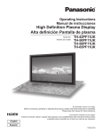
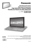
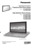
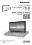
Operating Instructions
Manual de instrucciones
High Definition Plasma Display
Alta definición Pantalla de plasma
Model No.
No. de Modelo
TH-58PF12UK
TH-65PF12UK
Contents
Important Safety Instructions ··········································· 3
FCC STATEMENT ······························································· 4
Safety Precautions ···························································· 5
Maintenance ······································································· 6
Accessories ······································································· 7
Connections ······································································· 8
Power ON / OFF ······························································· 12
Selecting the input signal ···············································
Basic Controls ·································································
On-Screen Menu Displays ··············································
Specifications ··································································
Panasonic Professional Flat Panel Display Limited Warranty ··
LIMITED WARRANTY STATEMENT ································
Customer Service ····························································
14
15
17
19
20
21
22
The illustration shown is an image.
Before connecting, operating or adjusting this product, please read these instructions completely.
Please keep this manual for future reference.
La ilustración mostrada es una imagen.
Antes de conectar, utilizar o ajustar este producto, lea completamente este manual de instrucciones;
y guárdelo para consultarlo en el futuro en caso de ser necesario.
For more detailed instructions, refer to the Operating Instructions on the CD-ROM.
To view the Operating Instructions on the CD-ROM, you need a computer equipped with a CD-ROM drive, and
Adobe® Reader® (Version 7.0 or later is recommended) installed on your computer.
Depending on the operating system or settings on your computer, the Operating Instructions may not start automatically.
In this case, open the PDF file under \MANUAL\PDF manually to view the instructions.
Para obtener instrucciones más detalladas, consulte las instrucciones de manejo contenidas en el CD-ROM.
Para ver las instrucciones de manejo contenidas en el CD-ROM, se necesita un ordenador equipado con una
unidad de CD-ROM, y que tenga instalado Adobe® Reader® (se recomienda la versión 7.0 o posterior).
Dependiendo del sistema operativo o de las configuraciones del ordenador, las instrucciones de manejo pueden no iniciarse automáticamente.
En tal caso, abra manualmente el archivo PDF en \MANUAL\PDF para visualizar las instrucciones.
English
Español
TQB2AA0562
CAUTION
RISK OF ELECTRIC SHOCK
DO NOT OPEN
WARNING: To reduce the risk of electric shock, do not remove cover or back.
No user-serviceable parts inside. Refer servicing to qualified service personnel.
The lightning flash with
arrow-head within a triangle
is intended to tell the user
that parts inside the product
are a risk of electric shock
to persons.
The exclamation point within
a triangle is intended to
tell the user that important
operating and servicing
instructions are in the papers
with the appliance.
WARNING : To prevent damage which may result in fire or shock hazard, do not expose this apparatus to rain
or moisture.
Do not place containers with water (flower vase, cups, cosmetics, etc.) above the set.
(including on shelves above, etc.)
WARNING : 1) To prevent electric shock, do not remove cover. No user serviceable parts inside. Refer servicing to
qualified service personnel.
2) Do not remove the grounding pin on the power plug. This apparatus is equipped with a three pin
grounding-type power plug. This plug will only fit a grounding-type power outlet. This is a safety feature.
If you are unable to insert the plug into the outlet, contact an electrician.
Do not defeat the purpose of the grounding plug.
2
Important Safety Instructions
1) Read these instructions.
2) Keep these instructions.
3) Heed all warnings.
4) Follow all instructions.
5) Do not use this apparatus near water.
6) Clean only with dry cloth.
7) Do not block any ventilation openings. Install in accordance with the manufacturer’s instructions.
8) Do not install near any heat sources such as radiators, heat registers, stoves, or other apparatus (including
amplifiers) that produce heat.
9) Do not defeat the safety purpose of the polarized or grounding-type plug. A polarized plug has two blades with one
wider than the other. A grounding type plug has two blades and a third grounding prong. The wide blade or the
third prong are provided for your safety. If the provided plug does not fit into your outlet, consult an electrician for
replacement of the obsolete outlet.
10) Protect the power cord from being walked on or pinched particularly at plugs, convenience receptacles, and the
point where they exit from the apparatus.
11) Only use attachments / accessories specified by the manufacturer.
12) Use only with the cart, stand, tripod, bracket, or table specified by the manufacturer, or sold with
the apparatus. When a cart is used, use caution when moving the cart / apparatus combination
to avoid injury from tip-over.
13) Unplug this apparatus during lightning storms or when unused for long periods of time.
14) Refer all servicing to qualified service personnel. Servicing is required when the apparatus has been damaged
in any way, such as power-supply cord or plug is damaged, liquid has been spilled or objects have fallen into the
apparatus, the apparatus has been exposed to rain or moisture, does not operate normally, or has been dropped.
15) To prevent electric shock, ensure the grounding pin on the AC cord power plug is securely connected.
3
FCC STATEMENT
This equipment has been tested and found to comply with the limits for a Class B digital device, pursuant to Part
15 of the FCC Rules. These limits are designed to provide reasonable protection against harmful interference in a
residential installation. This equipment generates, uses and can radiate radio frequency energy and, if not installed
and used in accordance with the instructions, may cause harmful interference to radio communications. However,
there is no guarantee that interference will not occur in a particular installation. If this equipment does cause harmful
interference to radio or television reception, which can be determined by turning the equipment off and on, the user
is encouraged to try to correct the interference by one or more of the following measures:
• Reorient or relocate the receiving antenna.
• Increase the separation between the equipment and receiver.
• Connect the equipment into an outlet on a circuit different from that to which the receiver is connected.
• Consult the dealer or an experienced technician for help.
This device complies with Part15 of the FCC Rules. Operation is subject to the following two conditions:(1) This
device may not cause harmful interference, and (2) this device must accept any interference received, including
interference that may cause undesired operation.
FCC CAUTION:
To assure continued compliance, follow the attached installation instructions and use only shielded interface
cables when connecting to computer or peripheral devices. Any changes or modifications not expressly
approved by Panasonic Corp. of North America could void the user's authority to operate this device.
FCC Declaration of Conformity
Model No. TH-58PF12UK, TH-65PF12UK
Responsible Party:
Contact Source:
Panasonic Corporation of North America
One Panasonic Way 1F-10, Secaucus, NJ 07094
Panasonic Professional Display Company
Panasonic Plasma Concierge 1-800-973-4390
CANADIAN NOTICE:
This Class B digital apparatus complies with Canadian ICES-003.
Note:
Do not allow a still picture to be displayed for an extended period, as this can cause a permanent image retention to
remain on the Plasma Display.
Examples of still pictures include logos, video games, computer images, teletext and images displayed in 4:3 mode.
Trademark Credits
• VGA is a trademark of International Business Machines Corporation.
• Macintosh is a registered trademark of Apple Inc. USA.
• SVGA, XGA, SXGA and UXGA are registered trademarks of the Video Electronics Standard Association.
Even if no special notation has been made of company or product trademarks, these trademarks have been fully
respected.
• HDMI, the HDMI logo and High-Definition Multimedia Interface are trademarks or registered trademarks of HDMI
Licensing LLC.
4
Safety Precautions
CAUTION
This Plasma Display is for use only with the following optional accessories. Use with any other type of optional
accessories may cause instability which could result in the possibility of injury.
(All of the following accessories are manufactured by Panasonic Corporation.)
• Speakers .................................................... TY-SP58P10WK (for TH-58PF12UK),
TY-SP65P11WK (for TH-65PF12UK)
• Pedestal ..................................................... TY-ST58-K (for TH-58PF12UK), TY-ST65P11-K (for TH-65PF12UK)
• Mobile stand ............................................... TY-ST58PF10 (for TH-58PF12UK)
• Wall-hanging bracket (vertical) ................... TY-WK42PV7 (for TH-58PF12UK), TY-WK65PV7 (for TH-65PF12UK)
• Wall-hanging bracket (angled) ................... TY-WK42PR7 (for TH-58PF12UK), TY-WK65PR8 (for TH-65PF12UK)
• BNC Component Video Terminal Board ..... TY-42TM6A
• BNC Composite Video Terminal Board ...... TY-42TM6B
• BNC Dual Video Terminal Board ................ TY-FB9BD
• RCA Component Video Terminal Board ..... TY-42TM6Z
• RCA Composite Video Terminal Board ...... TY-42TM6V
• RGB Active Through Terminal Board ......... TY-42TM6G
• PC Input Terminal Board ............................ TY-42TM6P
• Composite / Component Video Terminal Board ... TY-42TM6Y
• BNC SDI Terminal Board ........................... TY-FB7SD
• HD-SDI Terminal Board ............................. TY-FB9HD
• HD-SDI Terminal Board with audio ............ TY-FB10HD
• Dual Link HD-SDI Terminal Board.............. TY-FB11DHD
• HDMI Terminal Board ................................. TY-FB8HM
• Dual HDMI Terminal Board ........................ TY-FB10HMD
• DVI-D Terminal Board ................................ TY-FB11DD
• Ir Through Terminal Board ......................... TY-FB9RT
• Wireless Presentation Board ..................... TY-FB10WPU
• AV Terminal Box ......................................... TY-TB10AV
• LAN Control Board ..................................... TY-FB12LC
• Anti Glare Filter .......................................... TY-AR58P10W (for TH-58PF12UK), TY-AR65P9W (for TH-65PF12UK)
• Touch Panel ............................................... TY-TP58P10S (for TH-58PF12UK), TY-TP65P10S (for TH-65PF12UK)
Always be sure to ask a qualified technician to carry out set-up.
Small parts can present choking hazard if accidentally swallowed. Keep small parts away from young children. Discard
unneeded small parts and other objects, including packaging materials and plastic bags/sheets to prevent them from being
played with by young children, creating the potential risk of suffocation.
When using the Plasma Display
Do not bring your hands, face or objects close to the
ventilation holes of the Plasma Display.
• Top of the Plasma Display is usually very hot due to the
high temperature of exhaust air being released through the
ventilation holes. Burns or personal injuries can happen if any
body parts are brought too close. Placing any object near the
top of the display could also result in heat damages to the object
as well as to the Display if its ventilation holes are blocked.
Be sure to disconnect all cables before moving the Plasma Display.
• Moving the Display with its cables attached might damage
the cables which, in turn, can cause fire or electric shock.
Disconnect the power plug from the wall outlet as a
safety precaution before carrying out any cleaning.
• Electric shocks can result if this is not done.
Clean the power cable regularly to prevent it from
becoming dusty.
• Built-up dust on the power cord plug can increase humidity
which might damage the insulation and cause fire. Unplug
the cord from the wall outlet and clean it with a dry cloth.
This Plasma Display radiates infrared rays, therefore it
may affect other infrared communication equipment.
Install your infrared sensor in a place away from direct
or reflected light from your Plasma Display.
Note:
Do not allow a still picture to be displayed for an extended
period, as this can cause a permanent image retention to
remain on the Plasma Display.
Examples of still pictures include logos, video games, computer
images, teletext and images displayed in 4:3 mode.
5
Safety Precautions / Maintenance
WARNING
Setup
Do not place the Plasma Display on sloped or unstable
surfaces.
• The Plasma Display may fall off or tip over.
Do not place any objects on top of the Plasma Display.
• If water spills onto the Plasma Display or foreign objects get
inside it, a short-circuit may occur which could result in fire or
electric shock. If any foreign objects get inside the Plasma
Display, please consult an Authorized Service Center.
Do not cover the ventilation holes.
• Doing so may cause the Plasma Display to overheat,
which can cause fire or damage to the Plasma Display.
Transport only in upright position!
• Transporting the unit with its display panel facing upright or
downward may cause damage to the internal circuitry.
If using the pedestal (optional accessory), leave a space
of 3 15/16” (10 cm) or more at the top, left and right, and
2 3/4” (7 cm) or more at the rear, and also keep the space
between the bottom of the display and the floor surface.
If using some other setting-up method, follow the manual
of it. (If there is no specific indication of installation
dimension in the installation manual, leave a space of
3 15/16” (10 cm) or more at the top, bottom, left and right,
and 2 3/4” (7 cm) or more at the rear.)
An apparatus with CLASS I construction shall be
connected to a mains socket outlet with a protective
earthing connection.
AC Power Supply Cord
The Plasma Display is designed to operate on 110 - 127
V AC, 50/60 Hz.
Do not use any power supply cord other than that
provided with this unit.
• Doing so may cause fire or electric shocks.
Securely insert the power cord plug as far as it will go.
• If the plug is not fully inserted, heat may be generated
which could cause fire. If the plug is damaged or the
wall socket plate is loose, they should not be used.
Do not handle the power cord plug with wet hands.
• Doing so may cause electric shocks.
Do not do anything that might damage the power cable.
When disconnecting the power cable, hold the plug,
not the cable.
• Do not make any modifications, place heavy objects on,
place near hot objects, heat, bend, twist or forcefully
pull the power cable. Doing so may cause damage to
the power cable which can cause fire or electric shock.
If damage to the cable is suspected, have it repaired at
an Authorized Service Center.
If the Plasma Display will not be used for a long period
of time, unplug the power cord from the wall outlet.
If problems occur during use
If a problem occurs (such as no picture or no sound),
or if smoke or an abnormal odor is detected from the
Plasma Display, unplug the power cord immediately.
• Continuous use of the Display under these conditions
might cause fire or permanent damage to the unit.
Have the Display evaluated at an Authorized Service
Center. Services to the Display by any unauthorized
personnel are strongly discouraged due to its high
voltage dangerous nature.
If water or foreign objects get inside the Plasma Display,
if the Plasma Display is dropped, or if the cabinet
becomes damaged, disconnect the power cord plug
immediately.
• A short may occur, which could cause fire. Contact an
Authorized Service Center for any repairs that need to be
made.
Maintenance
The front of the display panel has been specially treated. Wipe the panel surface gently using only a cleaning
cloth or a soft, lint-free cloth.
• If the surface is particularly dirty, wipe with a soft, lint-free cloth which has been soaked in pure water or water in which
neutral detergent has been diluted 100 times, and then wipe it evenly with a dry cloth of the same type until the surface
is dry.
• Do not scratch or hit the surface of the panel with fingernails or other hard objects, otherwise the surface may become
damaged. Furthermore, avoid contact with volatile substances such as insect sprays, solvents and thinner, otherwise
the quality of the surface may be adversely affected.
If the cabinet becomes dirty, wipe it with a soft, dry cloth.
• If the cabinet is particularly dirty, soak the cloth in water to which a small amount of neutral detergent has been added
and then wring the cloth dry. Use this cloth to wipe the cabinet, and then wipe it dry with a dry cloth.
• Do not allow any detergent to come into direct contact with the surface of the Plasma Display. If water droplets get
inside the unit, operating problems may result.
• Avoid contact with volatile substances such as insect sprays, solvents and thinner, otherwise the quality of the cabinet
surface may be adversely affected or the coating may peel off. Furthermore, do not leave it for long periods in contact
with articles made from rubber or PVC.
6
Accessories
Accessories Supplied
Check that you have the Accessories and items shown
Operating
Instruction book
CD-ROM
(Operating
instructions)
Fixing band × 1
AC cord
Remote Control Transmitter
N2QAYB000432
Batteries for the
Remote Control
Transmitter
(AA Size × 2)
Remote Control Batteries
Requires two AA batteries.
1. Pull and hold the hook, then
open the battery cover.
2. I n s e r t b a t t e r i e s - n o t e c o r r e c t
polarity ( + and -).
3. Replace the cover.
“AA” size
+
+
-
Helpful Hint:
For frequent remote control users, replace old batteries with Alkaline batteries for longer life.
Precaution on battery use
Incorrect installation can cause battery leakage and corrosion that will damage the remote control transmitter.
Disposal of batteries should be in an environment-friendly manner.
Observe the following precautions:
1. Batteries should always be replaced as a pair. Always use new batteries when replacing the old set.
2. Do not combine a used battery with a new one.
3. Do not mix battery types (example: “Zinc Carbon” with “Alkaline”).
4. Do not attempt to charge, short-circuit, disassemble, heat or burn used batteries.
5. Battery replacement is necessary when the remote control acts sporadically or stops operating the Plasma Display.
6. Do not burn or breakup batteries.
Batteries must not be exposed to excessive heat such as sunshine, fire or the like.
7
Connections
When connecting the speakers, be sure to use only the optional accessory speakers.
Refer to the speaker’s Installation Manual for details on speaker installation.
Speakers (Optional accessories)
1
2
Speaker
terminal (L)
Speaker
terminal (R)
2
AC cord connection (see page 12)
– AC cord fixing
Unplug the AC cord
Close
1 Plug the AC cord into
1
1
the display unit.
Plug the AC cord until it
clicks.
Push until
the hook
clicks.
Unplug the AC cord
pressing the two
knobs.
2 Fix the AC cord with the clamper
2
Note:
Make sure that the AC
cord is locked on both
the left and right sides.
which is attached to the unit. Open
For TH-58PF12UK:
Clampers are not installed to this
unit. Ensure there is sufficient slack
in the AC cord and firmly bind with
the supplied cable fixing band, etc.
Note:
When disconnecting the AC cord,
be absolutely sure to disconnect
the AC cord plug at the socket
outlet first.
2. Pull off.
1. Keep the
knob
pressed.
– Cable fixing band
Secure any excess cables with band as required.
Note:
One fixing band is supplied with this unit. In case of securing cables at two positions, please purchase it separately.
Pass the attached cable
fixing band through the clip
as shown in the figure.
To secure cables connected to Terminals, wrap the cable fixing band around them then
pass the pointed end through the locking block, as shown in the figure.
While ensuring there is sufficient slack in cables to minimize stress (especially
in the power cord), firmly bind all cables with the supplied fixing band.
To loosen:
Push the catch
To tighten:
Pull
2
1
Pull
R AUDIO
L
PR/CR/R
PB/CB/B
Y/G
AUDIO
COMPONENT/RGB IN
SLOT1
Optional Terminal
Board Insert Slot
(covered)
SLOT2
Dual HDMI Terminals
(equivalent of Dual HDMI
Terminal Board (TYFB10HMD)) (see page 11)
SLOT3
COMPONENT/RGB IN and Audio
IN Terminals (equivalent of BNC
Component Video Terminal Board
(TY-42TM6A)) (see page 11)
Note: At factory shipment, Terminal boards are installed in SLOT 2 and SLOT 3.
8
PC
IN
SERIAL
From EXTERNAL
monitor terminal
on Computer
(see page 9)
From SERIAL
Terminal on
Computer
(see page 10)
Connections
PC Input Terminals connection
(Female)
COMPUTER
AUDIO
PC IN
Conversion adapter
(if necessary)
Mini D-sub 15p
RGB
PC cable
Audio
(Male)
Stereo plug
Connect a cable which matches
the audio output terminal on the computer.
Notes:
• With regard to the typical PC input signals that are described in the applicable input signals list, adjustment values such
as for the standard picture positions and sizes have already been stored in this unit. You can add up to eight PC input
signal types that are not included in the list.
• Computer signals which can be input are those with a horizontal scanning frequency of 15 to 110 kHz and vertical scanning
frequency of 48 to 120 Hz. (However, the image will not be displayed properly if the signals exceed 1,200 lines.)
• The display resolution is a maximum of 1,440 × 1,080 dots when the aspect mode is set to “4:3”, and 1,920 × 1,080
dots when the aspect mode is set to “FULL”. If the display resolution exceeds these maximums, it may not be possible
to show fine detail with sufficient clarity.
• The PC input terminals are DDC2B-compatible. If the computer being connected is not DDC2B-compatible, you will need
to make setting changes to the computer at the time of connection.
• Some PC models cannot be connected to the set.
• There is no need to use an adapter for computers with DOS/V compatible Mini D-sub 15P terminal.
• The computer shown in the illustration is for example purposes only.
• Additional equipment and cables shown are not supplied with this set.
• Do not set the horizontal and vertical scanning frequencies for PC signals which are above or below the specified
frequency range.
• Component Input is possible with the pin 1, 2, 3 of the Mini D-sub 15P Connector.
• Change the “COMPONENT/RGB-IN SELECT” setting in the “SET UP” menu to “COMPONENT”
(when COMPONENT signal connection) or “RGB” (when RGB signal connection).
Signal Names for Mini D-sub 15P Connector
Pin No.
5
4
10 9
3
2
8
1
7
1
6
15 14 13 12 11
Pin Layout for PC Input
Terminal
2
3
4
5
Signal Name
R (PR/CR)
G (Y)
B (PB/CB)
NC (not connected)
GND (Ground)
Pin No.
6
7
8
9
10
Signal Name
GND (Ground)
GND (Ground)
GND (Ground)
+5 V DC
GND (Ground)
Pin No.
11
12
13
14
15
Signal Name
NC (not connected)
SDA
HD/SYNC
VD
SCL
9
Connections
SERIAL Terminals connection
The SERIAL terminal is used when the Plasma Display is controlled by a computer.
(Male)
COMPUTER
1
2
6
SERIAL
RS-232C Straight cable
3
7
4
8
5
9
Pin layout for SERIAL Terminal
(Female)
D-sub 9p
Notes:
• Use the RS-232C straight cable to connect the computer
to the Plasma Display.
• The computer shown is for example purposes only.
• Additional equipment and cables shown are not supplied
with this set.
The SERIAL terminal conforms to the RS-232C interface
specification, so that the Plasma Display can be controlled
by a computer which is connected to this terminal.
The computer will require software which allows the
sending and receiving of control data which satisfies the
conditions given below. Use a computer application such as
programming language software. Refer to the documentation
for the computer application for details.
RS-232C compliant
Asynchronous
9600 bps
None
8 bits
1 bit
-
Basic format for control data
The transmission of control data from the computer starts with
a STX signal, followed by the command, the parameters, and
lastly an ETX signal in that order. If there are no parameters,
then the parameter signal does not need to be sent.
STX
C1 C2 C3
Start
(02h)
:
P1 P2 P3 P4 P5
ETX
Colon
Parameter(s)
(1 - 5 bytes)
3-character
command (3 bytes)
End
(03h)
Notes:
• If multiple commands are transmitted, be sure to wait for
the response for the first command to come from this unit
before sending the next command.
• If an incorrect command is sent by mistake, this unit will
send an “ER401” command back to the computer.
• SL1A, SL1B, SL2A and SL2B of Command IMS are available
only when a dual input terminal board is attached.
10
2
3
5
4 • 6
7
8
1 • 9
RXD
TXD
GND
Non use
(Shorted in this set)
NC
These signal names are those of computer specifications.
Communication parameters
Signal level
Synchronization method
Baud rate
Parity
Character length
Stop bit
Flow control
Signal names for D-sub 9P connector
Details
Pin No.
Command
Command
PON
POF
AVL
AMT
Parameter
None
None
**
0
1
None
SL1
SL2
SL3
PC1
SL1A
SL1B
SL2A
SL2B
None
ZOOM
FULL
JUST
NORM
SELF
SJST
SNOM
SFUL
ZOM2
Control details
Power ON
Power OFF
Volume 00 - 63
Audio MUTE OFF
Audio MUTE ON
IMS
Input select (toggle)
Slot1 input
Slot2 input
Slot3 input
PC input
Slot1 input (INPUT1A)
Slot1 input (INPUT1B)
Slot2 input (INPUT2A)
Slot2 input (INPUT2B)
DAM
Screen mode select (toggle)
ZOOM (For Video/SD/PC signal)
FULL
JUST (For Video/SD signal)
4:3 (For Video/SD/PC signal)
Panasonic Auto (For Video signal)
JUST (For HD signal)
4:3 (For HD signal)
H-FILL (For HD signal)
ZOOM (For HD signal)
With the power off, this display responds to PON command only.
Connections
HDMI connection
This unit has terminal boards equivalent to Dual HDMI Terminal Board (TY-FB10HMD) and BNC Component Video Terminal
Board (TY-42TM6A) as standard equipment.
[Pin assignments and signal names]
Pin No.
1
2
3
4
5
6
7
8
9
10
Signal
T.M.D.S Data2+
T.M.D.S Data2
Shield
T.M.D.S Data2T.M.D.S Data1+
T.M.D.S Data1
Shield
T.M.D.S Data1T.M.D.S Data0+
T.M.D.S Data0
Shield
T.M.D.S Data0T.M.D.S Clock+
Pin No.
11
Signal
T.M.D.S Clock
Shield
12
T.M.D.S Clock-
13
CEC
R AUDIO
Reserved
(N.C. on device)
14
15
16
SLOT1
SLOT2
18
19
PR/CR/R PB/CB/B
Y/G
SLOT3
SCL
SDA
DDC/CEC
Ground
+5V Power
Hot Plug Detect
17
L
COMPONENT/RGB IN
PC
HDMI cables
3 1
19
HDMI
AV OUT
HDMI
AV OUT
DVD player
DVD player
4 2
18
Note:
Additional equipment and HDMI cables shown
are not supplied with this set.
COMPONENT / RGB connection
COMPONENT VIDEO OUT
PR
Example of input signal source
DVD
Digital TV-SET-TOP-BOX
(DTV-STB)
Y, PB, PR,
OUT
RCA-BNC
adapter
plug
PB
Y
L
AUDIO
OUT R
R AUDIO
L
PR/CR/R PB/CB/B
Y/G
COMPONENT/RGB IN
SLOT3
Computer
RGB Camcorder
or
Notes:
• Change the “COMPONENT/RGB-IN SELECT” setting in the “SET UP” menu to “COMPONENT”
(when COMPONENT signal connection) or “RGB” (when RGB signal connection).
• Additional equipment, cables and adapter plugs shown are not supplied with this set.
• SYNC ON G signal is needed.
11
Power ON / OFF
Connecting the AC cord plug to the Plasma Display.
Fix the AC cord plug securely to the Plasma Display with the clamper. (see page 8)
Connecting the plug to the Wall Outlet.
Note:
When disconnecting the AC cord, be absolutely sure to
disconnect the AC cord plug at the socket outlet first.
Press the Power switch on the Plasma Display to turn the
set on: Power-On.
INPUT
MENU
-/
VOL
+/
ENTER/
Power Indicator
Power Indicator: Green
Remote Control Sensor
Press the
button on the remote control to turn the Plasma Display off.
Power Indicator: Red (standby)
Press the
button on the remote control to turn the Plasma Display on.
Power Indicator: Green
Turn the power to the Plasma Display off by pressing the
when the Plasma Display is on or in standby mode.
switch on the unit,
Note:
During operation of the power management function, the power indicator turns
orange in the power off state.
12
Power ON / OFF
When first switching on the unit
Following screen will be displayed when the unit is turned on for the first time.
Select the items with the remote control. Unit buttons are invalid.
OSD LANGUAGE
English (UK)
OSD LANGUAGE
Deutsch
1
2
Select the language.
Set.
Français
Italiano
Español
ENGLISH (US)
Русский
PRESENT TIME SETUP
1
Select “DAY” or “PRESENT TIME OF DAY”.
2
Setup “DAY” or “PRESENT TIME OF DAY”.
SELECT
SET
PRESENT TIME SETUP
1
Select “SET”.
2
Set.
DISPLAY ORIENTATION
1
For vertical installation, select “PORTRAIT”.
2
Set.
PRESENT TIME OF DAY MON 99:99
SET
MON
DAY
99:99
PRESENT TIME OF DAY
PRESENT TIME SETUP
PRESENT TIME OF DAY MON 99:99
SET
TUE
DAY
10:00
PRESENT TIME OF DAY
DISPLAY ORIENTATION
LANDSCAPE
PORTRAIT
Notes:
• Once the items are set, the screens won't be displayed when switching on the unit next time.
• After the setting, the items can be changed in the following menus.
OSD LANGUAGE
PRESENT TIME SETUP
DISPLAY ORIENTATION
From the second time on, the below screen is displayed for a while (setting condition is an example).
PC
NANODRIFT HIGH MID
FULL
13
Selecting the input signal
Select the input signals to be connected by installing the optional Terminal Boards.
Press to select the input signal to be played back from the
equipment which has been connected to the Plasma Display.
Input signals will change as follows:
INPUT1
INPUT2A
INPUT2B
INPUT3
PC
SLOT2 is for dual input so that you can select INPUT2A or
INPUT2B for INPUT2.
INPUT2A : HDMI signal terminal in SLOT2
INPUT2B : HDMI signal terminal in SLOT2
Notes:
• Selecting is also possible by pressing the INPUT button on the unit.
• Input terminal will not be selected if the terminal board is not installed into the SLOT.
• Select to match the signals from the source connected to the component/RGB input
terminals.
• In 2 screen display, the same input mode cannot be selected for the main picture and
sub picture.
• Image retention (image lag) may occur on the plasma display panel when a still picture
is kept on the panel for an extended period. The function that darkens the screen slightly
is activated to prevent image retention, but this function is not the perfect solution to
image retention.
14
INPUT
MENU
-/
VOL
+/
INPUT
ENTER/
MENU
-/
VOL
+/
ENTER/
Basic Controls
Main Unit
Remote control sensor
Volume Adjustment
Volume Up “+” Down “–”
When the menu screen is
displayed:
“+” : press to move the cursor up
“–” : press to move the cursor down
(see page 17)
INPUT
MENU
-/
Main Power On / Off Switch
Power Indicator
The Power Indicator will light.
• Power-OFF .... Indicator not illuminated (The unit will
still consume some power as long as the
power cord is still inserted into the wall
outlet.)
• Standby ........ Red
Orange (When “Slot power” is set to
“On”.)
Orange (Depending on the type of
the function board installed, when the
power is supplied to the slot)
• Power-ON ...... Green
• DPMS (POWER MANAGEMENT)
....................... Orange (With PC input signal.)
VOL
+/
ENTER/
Enter / Aspect button
(see page 17)
MENU Screen ON / OFF
Each time the MENU button is pressed, the menu screen
will switch.
Normal Viewing
SOUND
PICTURE
POS. /SIZE
SET UP
INPUT button (Input signal selection)
(see page 14)
15
Basic Controls
Remote Control Transmitter
ACTION button
Press to make selections.
ASPECT button
Press to adjust the aspect.
Standby (ON / OFF) button
The Plasma Display must first be plugged
into the wall outlet and turned on at the
power switch (see page 12).
Press this button to turn the Plasma
Display On, from Standby mode. Press
it again to turn the Plasma Display Off to
Standby mode.
POS. /SIZE button
PICTURE button
Sound mute On / Off
Press this button to mute the sound.
Press again to reactivate sound.
Sound is also reactivated when power is
turned off or volume level is changed.
OFF TIMER button
The Plasma Display can be preset to switch to standby after a fixed period. The setting changes to 30
minutes, 60 minutes, 90 minutes and 0 minutes (off
timer cancelled) each time the button is pressed.
30
60
90
0
When three minutes remain, “OFF TIMER 3” will flash.
The off timer is cancelled if a power interruption
occurs.
AUTO SETUP button
Automatically adjusts the position/
size of the screen.
SET UP button
SOUND button
Volume Adjustment
Press the Volume Up “+” or Down “–”
button to increase or decrease the
sound volume level.
R button (see page 17)
Press the R button to return to
previous menu screen.
N button
POSITION buttons
INPUT button
Press to select INPUT1, INPUT2, INPUT3
and PC input SLOTS sequentially.
(see page 14)
When a dual input terminal board is
attached, A or B is displayed depending
on the selected input signal.
(Ex. INPUT1A, INPUT1B)
RECALL button
Press the “RECALL” button to
display the current system status.
1 Input label
NANODRIFT setting value
2 Aspect mode
3 Off timer
The off timer indicator is
displayed only when the off
timer has been set.
4 Clock display
PC
NANODRIFT HIGH MID
4:3
MULTI Window buttons
4
2
10:00
OFF TIMER
Digital Zoom
16
1
90
3
On-Screen Menu Displays
Remote Control
1 Display the menu screen.
Unit
Press several times.
MENU
Press to select.
(Example: PICTURE menu)
2 Select the item.
Each time the MENU button is pressed, the
menu screen will switch.
Normal Viewing
PICTURE
SET UP
SOUND
POS. /SIZE
Select.
PICTURE
Select.
NORMALIZE NORMAL
PICTURE MENU
PICTURE
BRIGHTNESS
COLOR
TINT
SHARPNESS
COLOR TEMP
COLOR MANAGEMENT
ADVANCED SETTINGS
STANDARD
25
0
0
0
5
NORMAL
OFF
Press.
(Example:
PICTURE menu)
MEMORY SAVE
MEMORY LOAD
MEMORY EDIT
3 Set.
Set.
Set.
Press.
4 Exit the menu.
Press several times.
MENU
Press.
Press
to return to the previous menu.
17
On-Screen Menu Displays
Overview
Note: Menu that cannot be adjusted is grayout. Adjustable menu changes depending on signal, input and menu setting.
POS. /SIZE
H-POS
H-SIZE
V-POS
V-SIZE
DOT CLOCK
CLOCK PHASE
1:1 PIXEL MODE
[ VIDEO ]
SIGNAL
SET UP
NORMALIZE NORMAL
AUTO SETUP
1/2
SIGNAL
SCREENSAVER
EXTENDED LIFE SETTINGS
COMPONENT/RGB-IN SELECT
RGB
PC
INPUT LABEL
POWER SAVE
OFF
STANDBY SAVE
OFF
POWER MANAGEMENT
OFF
AUTO POWER OFF
OFF
OSD LANGUAGE
ENGLISH (US)
0
0
0
0
0
0
OFF
3D Y/C FILTER (NTSC)
COLOR SYSTEM
3 : 2 PULLDOWN
Panasonic AUTO (4 : 3)
REFRESH RATE
NOISE REDUCTION
ON
AUTO
OFF
4:3
100 Hz
OFF
SCREENSAVER
PRESENT TIME OF DAY 99:99
START
SCROLLING BAR ONLY
FUNCTION
OFF
MODE
EXTENDED LIFE SETTINGS
EXPRESS SETTINGS
CUSTOM SETTINGS
RESET
SET UP
2/2
MULTI DISPLAY SETUP
MULTI PIP SETUP
PORTRAIT SETUP
SET UP TIMER
PRESENT TIME SETUP
DISPLAY ORIENTATION LANDSCAPE
MULTI DISPLAY SETUP
HORIZONTAL SCALE
VERTICAL SCALE
SEAM HIDES VIDEO
LOCATION
AI-SYNCHRONIZATION
OFF
×2
×2
OFF
A1
OFF
MULTI PIP SETUP
PICTURE
SOUND
NORMALIZE NORMAL
PICTURE MENU
PICTURE
BRIGHTNESS
COLOR
TINT
SHARPNESS
COLOR TEMP
COLOR MANAGEMENT
ADVANCED SETTINGS
MULTI DISPLAY SETUP
STANDARD
25
0
0
0
5
NORMAL
OFF
1/2
NORMALIZE NORMAL
AUDIO MENU
BASS
MID
TREBLE
BALANCE
SURROUND
AUDIO OUT (PIP)
STANDARD
0
0
0
0
OFF
MAIN
MULTI PIP
DISPLAY MODE
TRANSPARENCY
TRANSPARENCY LEVEL
INSERT
INSERT LEVEL
BLEND PIP
—
OFF
0%
OFF
1
PORTRAIT SETUP
SDI SOUND OUTPUT
MEMORY SAVE
MEMORY LOAD
MEMORY EDIT
LEFT CHANNEL
RIGHT CHANNEL
SOUND OUT
LEVEL METER
2/2
CHANNEL 1
CHANNEL 1
OFF
OFF
PORTRAIT SETUP
SEAM HIDES VIDEO
VIEWING AREA
LOCATION
AI-SYNCHRONIZATION
OFF
OFF
16:9
1
OFF
SET UP TIMER
PRESENT TIME OF DAY 99:99
ADVANCED SETTINGS
POWER ON FUNCTION
POWER ON TIME
POWER OFF FUNCTION
POWER OFF TIME
NORMALIZE NORMAL
BLACK EXTENSION
INPUT LEVEL
GAMMA
AGC
W/B HIGH R
W/B HIGH G
W/B HIGH B
W/B LOW R
W/B LOW G
W/B LOW B
18
0
0
OFF
0:00
OFF
0:00
2.2
OFF
0
0
0
0
0
0
PRESENT TIME SETUP
PRESENT TIME OF DAY MON 99:99
SET
MON
DAY
99:99
PRESENT TIME OF DAY
Specifications
TH-58PF12UK
Power Source
Power Consumption
Power on
Stand-by condition
Power off condition
Plasma Display panel
Screen size
(No.of pixels)
Operating condition
Temperature
Humidity
Applicable signals
Scanning format
PC signals
Connection terminals
HDMI A-B
COMPONENT/RGB IN
PC IN
SERIAL
SPEAKERS
Accessories Supplied
Remote Control Transmitter
Batteries
Fixing band
Dimensions (W × H × D)
Mass (weight)
main unit only
with speakers
TH-65PF12UK
110 - 127 V AC, 50/60 Hz
715 W
745 W
Save OFF 1.0 W, Save ON 0.5 W
Save OFF 1.0 W, Save ON 0.5 W
0.2 W
0.2 W
Drive method : AC type 58-inch,
Drive method : AC type 65-inch,
16:9 aspect ratio
16:9 aspect ratio
50.5” (1,284 mm) (W) × 28.4” (722 mm) (H)
56.4” (1,434 mm) (W) × 31.7” (806 mm) (H)
× 58.0” (1,473 mm) (diagonal)
× 64.7” (1,645 mm) (diagonal)
2,073,600 (1,920 (W) × 1,080 (H))
[5,760 × 1,080 dots]
32 °F - 104 °F (0 °C - 40 °C)
20 % - 80 %
525 (480) / 60i · 60p, 625 (575) / 50i · 50p, 750 (720) / 60p · 50p, 1125 (1080) / 60i · 60p · 50i · 50p
· 24p · 25p · 30p · 24sF, 1250 (1080) / 50i
VGA, SVGA, XGA, SXGA
UXGA ···· (compressed)
Horizontal scanning frequency 15 - 110 kHz
Vertical scanning frequency 48 - 120 Hz
TYPE A Connector × 2
with sync 1.0 Vp-p (75 Ω)
0.7 Vp-p (75 Ω)
0.5 Vrms
Y or G with sync 1.0 Vp-p (75 Ω)
Y or G without sync 0.7 Vp-p (75 Ω)
B/PB/CB : 0.7 Vp-p (75 Ω)
R/PR/CR : 0.7 Vp-p (75 Ω)
HD/VD: 1.0 - 5.0 Vp-p (high impedance)
0.5 Vrms
AUDIO IN (M3 JACK)
EXTERNAL CONTROL TERMINAL (D-SUB 9PIN)
RS-232C COMPATIBLE
6 Ω, 16 W [8 W + 8 W] (10 % THD)
8 Ω, 20 W [10 W + 10 W] (10 % THD)
Y/G (BNC)
PB/B (BNC), PR/R (BNC)
AUDIO IN (RCA PIN JACK × 2)
(HIGH-DENSITY MINI D-SUB 15PIN)
N2QAYB000432
AA Size × 2
TMME203 × 1
55.1” (1,399 mm) × 33.2” (843 mm) × 3.9” (99 mm) 61.2” (1,554 mm) × 36.5” (925 mm) × 3.9” (99 mm)
approx. 105.8 lbs
approx. 116.8 lbs
approx. 130.0 lbs
approx. 143.3 lbs
Note:
Design and specifications are subject to change without notice. Mass and dimensions shown are approximate.
19
(for the U.S.A and Puerto Rico)
Panasonic Professional Display Company
Unit of Panasonic Corporation of
North America
One Panasonic Way 1F-10
Secaucus, NJ 07094
Panasonic Professional Flat Panel Display
Limited Warranty
Panasonic Professional Display Company. (referred to
as “the Warrantor”) will repair this product and all
included accessories with new or refurbished parts,
free of charge in the USA or Puerto Rico, of the
original purchase in the event of a defect in materials or
workmanship as follows:
Models or Parts
Part
Warranty
Professional Flat
Panel Display
2 Years
Labor
Warranty
2 Years
On-site or carry-in service in the USA and Puerto Rico
may be obtained during the warranty period by contacting
Panasonic Professional Display Company Service toll free
at 1-800-973-4390.
This warranty is extended only to the original purchaser
and is non transferable. A purchase receipt or other
proof of date of original purchase will be required before
warranty service is rendered.
This warranty only covers failures due to defects in
materials or workmanship, which occur during normal
use. The warranty does not cover damage which occur
in shipment, or failures which are caused by products
not supplied by the warrantor, or failures which result
from improper installation, set-up adjustments, improper
antenna, inadequate signal pickup, maladjustment of
consumer controls, improper operation, power line surge,
improper voltage supply, lighting damage, or service by
anyone other than an authorized repair facility, or
damage that is attributable to acts of God.
LIMITS AND EXCLUSIONS
There are no express warranties except as listed above.
THE WARRANTOR SHALL NOT BE LIABLE FOR
INCIDENTAL OR CONSEQUENTIAL DAMAGES
(INCLUDING, WITHOUT LIMITION, DAMAGE
TO DISCS) RESULTING FROM THE USE OF THIS
PRODUCT, OR ARISING OUT OF ANY BREACH OF
THE WARRANTY. ALL EXPRESS AND IMPLIED
WARRANTIES, INCLUDING THE WARRANTIES
OF MERCHANTABILITY AND FITNESS FOR
PARTICULAR PURPOSE, ARE LIMITED TO THE
APPLICABLE WARRANTY PERIOD SET FORTH
ABOVE.
Some states do not allow the exclusion or limitation
of incidental or consequential damages, or limitations
on how long an implied warranty lasts, so the above
exclusions or limitations may nor apply to you. This
warranty gives you specific legal rights and you may
other rights, which vary from state to state.
If you have a problem with this product that is not
handled to your satisfaction, then write the Consumer
Affairs Department at the Company address indicated
above.
In the USA and Puerto Rico
FOR SERVICE
CALL TOLL FREE
1-800-973-4390
20
(for Canada)
Panasonic Canada Inc.
5770 Ambler Drive, Mississauga, Ontario L4W 2T3
LIMITED WARRANTY STATEMENT
Panasonic Canada Inc. (also known as PCI) warrants this product to be free of
defects in material and workmanship under normal use during the applicable
warranty coverage period described below. PCI agrees to repair, or at its option,
exchange, any part that becomes defective. However, the product must be
purchased and serviced in Canada. The product or part that shows evidence of
defect must be delivered prepaid or carried in to an authorized Panasonic Broadcast
Service Center. This warranty does not cover shipping costs.
The warranty coverage period is one year for both parts and labour beginning with
the date of original end user purchase, subject to the exceptions as stated below.
Repaired or replacement parts supplied during the warranty coverage period carry
the unexpired portion of the original warranty coverage period. Proof of product
purchase is a condition of warranty service. The owner must produce the product
purchase receipt or other satisfactory evidence of date of original purchase.
This warranty does not apply to external appearance items, such as handles, knobs,
safety windows, etc. This warranty does not apply to any part, or parts, of the
product, installed, altered, repaired or misused in any way that, in the opinion of PCI,
affects the reliability of or detracts from the performance of the product.
For products requiring routine preventive maintenance, that maintenance must be
performed in order to maintain warranty coverage.
Serial numbers that have been altered, defaced or removed void this warranty. This
warranty does not cover replacements or repairs necessitated by loss or damage
resulting from any cause beyond the control of PCI.
Marking or retained images (sometimes called “burn-in”) resulting from the display of
fixed images on video display products are not defects and are not covered under
this warranty.
THIS EXPRESS, LIMITED WARRANTY IS IN LIEU OF ALL OTHER
WARRANTIES, EXPRESS OR IMPLIED, INCLUDING ANY IMPLIED
WARRANTIES OF MERCHANTABILITY AND FITNESS FOR A PARTICULAR
PURPOSE. IN NO EVENT WILL PANASONIC CANADA INC. BE LIABLE FOR
ANY SPECIAL, INDIRECT OR CONSEQUENTIAL DAMAGES.
In certain instances, some jurisdictions do not allow the exclusion or limitation of
incidental or consequential damages, or the exclusion of implied warranties, so the
above limitations and exclusions may not be applicable.
WARRANTY COVERAGE PERIOD EXCEPTIONS
Item
Video Tape
P2/SD Cards
Video Heads
D5 Video heads
Maintenance Items
Colour Camera CCD
Imaging Block
Parts
30 days—Replacement only
(content not covered)
(Content not covered)
1 year or 2,000 hrs. (prorated)
Whichever comes first
1 year or 1,000 hrs.
Whichever comes first
90 days
2 years
BT-H Series LCD Monitors 2 years
3 years or 17,000 hrs.
* DLP™ Projectors
Whichever comes first
3 years or 2,500 hrs.
* LCD Projectors above
Whichever comes first
2,500 ANSI Lumens
3 years or 1,500 hrs.
* LCD Projectors below
Whichever comes first
2,500 ANSI Lumens
50% of the rated lamp life or 1 year.
Projector Lamps
Whichever comes first
103 inch Plasma displays 3 year (burn-in not covered)
1 year plus balance (if any) of
Hard Drive Disk Unit
the original Manufacturer’s
Limited Warranty.
(Content not covered)
Labour
N/A
N/A
1 year or 2,000 hrs.
Whichever comes first
1 year or 1,000 hrs.
Whichever comes first
90 days
1 year
1 year
3 years or 17,000 hrs.
Whichever comes first
3 years or 2,500 hrs.
Whichever comes first.
3 years or 1,500 hrs.
Whichever comes first
50% of the rated lamp life or 1 year.
Whichever comes first.
3 year
1 year
• Dust, smoke, rental/staging environment and twenty-four/seven operation,
dramatically decreases the interval between performances of routine preventive
maintenance required to maintain this warranty coverage.
Warranty Service
If the product needs to be shipped for service, carefully pack (preferably in the
original carton) and enclose a letter, detailing the complaint. Send prepaid and
adequately insured to the local authorized Panasonic Service Centre in your
area or to Panasonic Technical Support and Product Services Department, 5770
Ambler Drive, Mississauga, Ontario, L4W 2T3. Shipping to the latter location
requires a return authorization before shipment. No liability is assumed for loss
or damage to the product while in transit.
21
22
Note
Customer’s Record
The model number and serial number of this product can be found on its back cover. You should note this serial number in
the space provided below and retain this book, plus your purchase receipt, as a permanent record of your purchase to aid in
identifi cation in the event of theft or loss, and for Warranty Service purposes.
Model Number
Serial Number
© Panasonic Corporation 2009
Panasonic Professional Display Company
Unit of Panasonic Corporation of North America
Executive Office :
One Panasonic Way 1F-10, Secaucus, NJ 07094
Panasonic Canada Inc.
5770 Ambler Drive
Mississauga, Ontario
L4W 2T3
Printed in U.S.A.