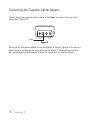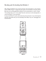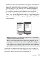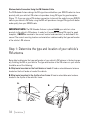
1
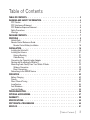
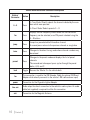
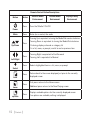
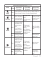
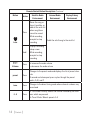
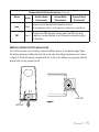
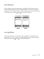
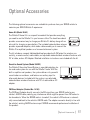
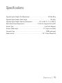
Table of Contents Table of Contents. . . . . . . . . . . . . . . . . . . . . . . . . . . . . . 3 Warning and Safety Information. . . . . . . . . . . . . . . . . . . . . . 4 FCC Caution. . . . . . . . . . . . . . . . . . . . . . . . . . . . . . . . . . 4 FCC Interference Statement. . . . . . . . . . . . . . . . . . . . . . . . . . . . 4 FCC Radiation Exposure Statement. . . . . . . . . . . . . . . . . . . . . . . . . 5 Safety Precautions. . . . . . . . . . . . . . . . . . . . . . . . . . . . . . . . 5 Warnings . . . . . . . . . . . . . . . . . . . . . . . . . . . . . . . . . . . 6 Package Contents. . . . . . . . . . . . . . . . . . . . . . . . . . . . . . 7 Controls. . . . . . . . . . . . . . . . . . . . . . . . . . . . . . . . . . . 9 Vehicle Dock. . . . . . . . . . . . . . . . . . . . . . . . . . . . . . . . . . 9 Remote Control Reference Guide. . . . . . . . . . . . . . . . . . . . . . . . . 11 Remote Control Battery Installation. . . . . . . . . . . . . . . . . . . . . . . 15 Installation. . . . . . . . . . . . . . . . . . . . . . . . . . . . . . . . . 16 Installing the Vehicle Kit. . . . . . . . . . . . . . . . . . . . . . . . . . . . . 16 Installing the Antenna . . . . . . . . . . . . . . . . . . . . . . . . . . . . . . 21 Antenna Mounting . . . . . . . . . . . . . . . . . . . . . . . . . . . . . . 21 Cable Routing. . . . . . . . . . . . . . . . . . . . . . . . . . . . . . . . 24 Connecting the Cigarette Lighter Adapter . . . . . . . . . . . . . . . . . . . . . . 30 Docking and Un-docking the Stiletto 2. . . . . . . . . . . . . . . . . . . . . . . 31 Maximizing Audio Quality From Your Stiletto 2 Radio . . . . . . . . . . . . . . . . . 32 Wireless Connection. . . . . . . . . . . . . . . . . . . . . . . . . . . . . 32 Direct Connections. . . . . . . . . . . . . . . . . . . . . . . . . . . . . . 48 Subscribing to the SIRIUS Service. . . . . . . . . . . . . . . . . . . . . . . . . 51 Operation . . . . . . . . . . . . . . . . . . . . . . . . . . . . . . . . . . 52 Battery Charging . . . . . . . . . . . . . . . . . . . . . . . . . . . . . . . . 52 Presets . . . . . . . . . . . . . . . . . . . . . . . . . . . . . . . . . . . . 52 Direct Channel Tuning. . . . . . . . . . . . . . . . . . . . . . . . . . . . . . 53 Jump Feature. . . . . . . . . . . . . . . . . . . . . . . . . . . . . . . . . 54 Auto Shutdown . . . . . . . . . . . . . . . . . . . . . . . . . . . . . . . . 55 Low Light Mode. . . . . . . . . . . . . . . . . . . . . . . . . . . . . . . . 55 Troubleshooting. . . . . . . . . . . . . . . . . . . . . . . . . . . . . . 56 Optional Accessories. . . . . . . . . . . . . . . . . . . . . . . . . . . . 57 Warranty. . . . . . . . . . . . . . . . . . . . . . . . . . . . . . . . . . 58 Specifications. . . . . . . . . . . . . . . . . . . . . . . . . . . . . . . . 59 Copyrights & Trademarks . . . . . . . . . . . . . . . . . . . . . . . . . 60 SIRIUS ID. . . . . . . . . . . . . . . . . . . . . . . . . . . . . . . . . . . 61 [ Table of Contents ] Warning and Safety Information FCC Caution Any changes or modifications not expressly approved by the party responsible for compliance could void the user’s authority to operate this equipment. This device complies with part 15 of the FCC Rules. Operation is subject to the following two conditions: 1. This device may not cause harmful interference, and 2. This device must accept any interference received, including interference that may cause undesired operation. This transmitter must not be co-located or operating in conjunction with any other antenna or transmitter. FCC Interference Statement This equipment has been tested and found to comply with the limits for a Class B digital device, pursuant to Part 15 of the FCC Rules. These limits are designed to provide reasonable protection against harmful interference in a residential installation. This equipment generates, uses and can radiate radio frequency energy and, if not installed and used in accordance with the instructions, may cause harmful interference to radio communications. However, there is no guarantee that interference will not occur in a particular installation. If this equipment does cause harmful interference to radio or television reception, which can be determined by turning the equipment off and on, the user is encouraged to try to correct the interference by one of the following measures: — Reorient or relocate the receiving antenna. — Increase the separation between the equipment and receiver. — Connect the equipment into an outlet on a circuit different from that to which the receiver is connected. — Consult the dealer or an experienced radio/TV technician for help. [ Warning and Safety Information ] FCC Radiation Exposure Statement This equipment complies with the FCC radiation exposure limits set forth for an uncontrolled environment. This equipment should be installed and operated with minimum distance of 1.5 cm between the radiator and your body. Safety Precautions Be sure to observe the following warnings. Failure to follow these safety instructions and warnings may result in a serious accident and/or personal injury. • Installation must be performed according to this installation guide. SIRIUS is not responsible for issues arising from installations not performed according to the procedures in this guide. • Do not operate the SIRIUS radio in a way that might divert your attention from driving safely. As a driver, you alone are responsible for safely operating your vehicle in accordance with traffic safety laws at all times. • Do not install the unit where it may obstruct your view through the windshield, or of your vehicle’s indicator displays. • Do not install the unit where it may hinder the function of safety devices such as an airbag. Doing so may prevent the airbag from functioning properly in the event of an accident. • To avoid short circuits, do not open the unit, and never put or leave any metallic objects (coins, tools, etc.) inside the unit. • If the unit emits smoke or unusual odors, turn the power off immediately, and disconnect the unit from any power source. • Do not drop the unit or subject it to strong shocks. • The installation and use suggestions contained in this installation manual are subject to any restrictions or limitations that may be imposed by applicable law. The purchaser should check applicable law for any restrictions or limitations before installing and/or operating this unit. • Do not install the FM Extender Cable where it will hinder or block your view. In some states it may be illegal to mount it on the windshield of your vehicle. Check applicable law [ Warning and Safety Information ] for any restrictions or limitations before installing the extender cable on your windshield. • Do not install the FM Extender Cable where it may hinder the function of safety devices such as an airbag. Doing so may prevent the airbag from functioning properly in the event of an accident. Warnings Notice To Drivers In California and Minnesota State law prohibits drivers in California and Minnesota from using suction mounts on their windshields while operating motor vehicles. Other dashboard or friction mounting options should be used. SIRIUS does not take any responsibility for any fines, penalties, or damages that may be incurred as a result of disregarding this notice. (See California Vehicle Code Section 26708(a); Minnesota Statutes 2005, Section 169.71) Operating Temperature The SIRIUS Cigarette Lighter Adapter is designed to operate between -20° to +85° C (-4° to +185° F). Avoid leaving it in a vehicle or elsewhere where the temperature may fall outside this range. Cleaning and Maintenance If the vehicle dock becomes dirty, turn the power off and wipe it clean with a soft cloth. Do not use hard cloths, strong cleaning fluids, paint thinner, alcohol, or other volatile solvents to clean. These may cause damage to the unit. Cigarette Lighter Adapter The vehicle dock cannot be powered directly from a vehicle’s 12 VDC power system. It must be powered using the included Cigarette Lighter Adapter only. Connecting the vehicle dock directly to the vehicle’s 12 VDC power system may result in damage to the vehicle dock or SIRIUS radio, or both. [ Warning and Safety Information ] Package Contents The following items are included with your purchase of the SIRIUS Stiletto 2 Vehicle Kit. Unpack the kit carefully and make sure that everything shown is present. If anything is missing or damaged, or if the kit fails to operate properly, notify your dealer immediately. It is recommended that you retain the original carton and packing materials in case you need to ship your kit in the future. mute back home options display + preset tune 1 2 3 4 5 1 2 6 7 8 9 0 4 5 7 8 9 jump 0 FM fm jump tune preset Vehicle Dock Magnetic Antenna 3 6 Remote Control Antenna Cover/Tail Vehicle Mounts Mounting Screws Cigarette Lighter Adapter Alcohol Swab [ Package Contents ] FM Extender Cable [ Package Contents ] Suction Cups (2) Self Adhesive Cable Guides (3) Controls Vehicle Dock Figure 1 and the table following identify and describe the buttons, connectors, and features of the vehicle dock. Lock lock Direct Entry Tune/ Preset Buttons Jump FM 1 2 3 4 5 6 7 8 9 0 fm IR Remote Receiver jump tune preset Tune Preset Preset Mode Indicator Tune Mode Indicator FM OUT ANT POWER LINE OUT Figure 1 [ Controls ] Vehicle Dock Button and Connector Descriptions Button/ Connector 0–9 Action Press Description In Tune Mode: Directly selects the channel indicted by the numbers which were pressed In Preset Mode: Selects presets 0 – 9 fm Press jump Press tune Press preset Press lock Toggle fm power line out ant. Displays the FM Frequency screen where the FM transmitter frequency can be selected, or an FM preset selected using the 0 – 9 buttons Jumps to a preselected traffic/weather channel A second press returns to the previous channel or song/show Changes to the direct tuning mode where channel numbers may be entered Changes to the preset mode and displays the list of preset channels The second and subsequent press cycles through the preset banks, A, B, and C Secures the Stiletto 2 in the vehicle dock This connection is used for the FM Extender Cable (or optional FM Direct Adapter which directly connects to the vehicle’s FM radio antenna input) Connection for the Cigarette Lighter Adapter Audio output for direct connection to the vehicle’s audio system. An audio cable (not supplied) is required to utilize this connection Connection for the Magnetic Antenna 10 [ Controls ] Remote Control Reference Guide Figure 2 and the table following identify and describe the buttons of the remote control. The remote control works when the Stiletto 2 is in the vehicle dock. Power Back back mute Mute home Home Select Media Dial (CCW) Rewind Media Dial (CW) Options Fast-Forward options display Rewind Love Preset Tune Jump + preset tune 1 2 3 4 5 6 7 8 9 jump 0 FM Display Fast-Forward Play/Pause Volume Numeric Keypad FM Figure 2 [ Controls ] 11 Remote Control Button Descriptions Button Action Satellite Radio Environment Internet Radio Environment Press Turns the Stiletto 2 On/Off Press Mutes (or un-mutes) the audio Replay/Library Environment Power Mute Pressing Up is equivalent to turning the Media Dial counter-clockwise Up/Down Press Pressing Down is equivalent to turning the Media Dial clockwise If listening, displays channel or category list If in a list, menu, or prompt, scrolls to next or previous item Press Left/Right Select Pressing Right is equivalent to Fast-Forward Pressing Left is equivalent to Rewind Press Selects highlighted item in a list, menu, or prompt Press Returns back to the screen displayed just prior to the currently displayed screen back Press home Press options 12 [ Controls ] First press returns to the Home screen Additional press returns to the Now Playing screen Displays available options for the currently displayed screen If no options are available, nothing is displayed Remote Control Button Descriptions Continued Button Action Satellite Radio Environment Internet Radio Environment Replay/Library Environment Press Cycles between the normal/near and car/far display mode, artist name, and song title when in the channel browsing mode Press Pauses a broadcast or resumes playing a paused broadcast display Play/Pause Press Rewind Hold Press Fast-Forward Hold If listening, rewinds a broadcast to the previous song or show If in a channel or preset list, moves through categories or preset banks If listening, rewinds through a broadcast If listening, fast-forwards in the replay buffer to the next song or show If in a channel or preset list, moves through categories or preset banks Fast-Forwards through the replay buffer If playing, mutes audio If muted, resumes playing If listening and muted, resumes playing If in a channel or category list, moves through channel categories If listening and muted, resumes playing If in a channel or category list, moves through channel categories Pauses or resumes playing the current song or show Skips to the beginning of the song or show Rewinds through song or show Skips to the next song or show Fast-Forwards through song or show [ Controls ] 13 Remote Control Button Descriptions Continued Button Action Press Satellite Radio Environment Replay/Library Environment Saves the song or show if possible, or adds to the wish list when song/show cannot be saved While recording, prompts to stop recording Love Internet Radio Environment Adds the artist/song to the wish list Displays recording setup screen Hold +/– Volume Press preset Press tune Press 0-9 Press While recording, prompts to stop recording + increases the audio volume — decreases the audio volume Changes to the preset mode and displays the list of preset channels A second and subsequent press cycles through the preset banks, A, B, and C Changes to the direct tuning mode where channel numbers may be entered In Tune Mode: Directly selects the channel indicted by the numbers which are pressed In Preset Mode: Selects presets 0–9 14 [ Controls ] Remote Control Button Descriptions Continued Button Action jump Press FM Press Satellite Radio Environment Internet Radio Environment Replay/Library Environment Jumps to a preselected traffic/weather channel A second press returns to the previous channel or song/show Displays the FM Frequency screen where the FM transmitter frequency can be selected, or an FM preset selected using the 0–9 buttons Remote Control Battery Installation To install the remote control battery, locate the battery drawer on the bottom edge. Open the battery drawer by holding the latch tab to the right and sliding the drawer out as shown in Figure 3. Place the battery in drawer with the + side of the battery facing up and slide the drawer back into the remote control. + Latch Tab Latch Tab Figure 3 [ Controls ] 15 Installation SIRIUS suggests professional installation of this product in your vehicle. Professional instal lation provides an experienced technician to install this product in your vehicle, advice for selecting a suitable mounting location, installation of the antenna, and routing all the neces sary wires and cables. An installer will have the necessary audio connection accessories to provide optimal audio output of the SIRIUS radio directly to your vehicle’s audio system. Ask your SIRIUS retailer if they provide professional installation services, or can recommend a professional installation service. Installing the Vehicle Kit When installing the vehicle dock, choose a location in your vehicle where the radio will not block your vision, interfere with the vehicle controls, or obstruct the air bag. The location should be easily accessible and provide good visibility of the display, and should not be located where it will be in direct sunlight which will affect the visibility of the display screen. The right side of the vehicle dock which has the Lock button should also not be obstructed. The mounting accessories necessary to install the vehicle dock in a vehicle are provided. Figure 4 shows two examples of the Stiletto 2 mounted in a vehicle: A is the console mount method using the adhesive mount, and B is the vent mount method. 16 [ Installation ] B. back home options display 1 2 6 3 7 8 fm back jump 4 9 tune 5 0 preset home options display 1 2 6 3 7 8 fm jump 4 9 tune 5 0 preset A. Figure 4 Depending upon the mounting method you select, the mount should be assembled as described in one of the following two sections. In choosing a mounting location, be sure that position chosen will not block access to the Lock button on the right side of the vehicle dock. Console Mount Method (A) To assemble and mount the vehicle dock for the console mount method A as shown in Figure 4: 1. Attach the adhesive foot to the vehicle dock using the provided screws. (Figure 5) 2. Before adhering the mount to the console, be sure to select your mounting position carefully because once the mount has been adhered to a surface, it will not be possible to remove it and adhere it again. 3. Clean the selected mounting surface area in the vehicle with the alcohol swab. 4. Unscrew the adhesive foot from the mounting bracket. Peel the protective material off the adhesive on the foot and press the foot firmly against the vehicle surface. 5. The adhesive mount should then be allowed to adhere for a minimum of 2-4 hours before use. Best adhesion occurs after 24 hours. When the adhesive foot has achieved sufficient adhesion, reattach the vehicle dock to the foot. [ Installation ] 17 Adhesive Mounting Foot Bracket Figure 5 18 [ Installation ] Vehicle Dock Vent Mount Method (B) To assemble and mount the vehicle dock for the vent mount method B as shown in Figure 4: 1. Assemble the vent mount clip as shown in Figure 6. Note that the lower arm may be attached in two different positions. You should assemble the vent clip in the configuration that works best in your particular vehicle. Figure 6 illustrates both possible configurations of the vent clip. 2. Attach the vent clip to the vehicle dock using the provided screws. (Figure 7) 3. Slide the vent clip portion of the mount into a vent in your vehicle, insuring that one of the vent louvers slides between the upper and lower portions of the two clip arms, and hooks the rear of the louver. Figure 6 [ Installation ] 19 Vent Clip Vehicle Dock Clip Arms Figure 7 20 [ Installation ] Installing the Antenna The installation of the magnetic antenna consists of two installation steps: • Mounting the magnetic antenna and cover/tail on the vehicle • Routing the antenna cable through the vehicle to the SIRIUS radio or vehicle dock The following sections provide instructions for both installation steps. Antenna Mounting The SIRIUS Magnetic Mount Vehicle Antenna has a strong magnetic mount designed to hold the antenna in place during normal driving conditions (highway/city). This also allows for easy removal for transferring the antenna to other vehicles. Figure 8 shows the optimal mounting location for the antenna on several types of vehicles. These mounting positions should be observed when installing the antenna: • Sedan/Coupe/SUV/Mini-Van: Install the antenna at the rear center of the roof, near the rear window. • Pickup Truck: Install the antenna at the front center of the roof, near the windshield. • Convertible: Install the antenna at the front center of the trunk lid, near the rear window. The SIRIUS antenna needs to have an unobstructed area of 3 inches by 3 inches around it. It is important to mount the antenna where no obstructions will block the antenna from receiving the SIRIUS signal. Objects which can obstruct the antenna could be a roof rack, a sunroof, a roof mounted cargo container, another antenna, etc. If your vehicle has a potential obstruction, be sure that the SIRIUS antenna is mounted at least 3 inches away from it (but no closer than 3 inches from the roof edge, or trunk lid in the case of a convertible). [ Installation ] 21 Sedan/Coupe Pickup Truck SUV/Mini-Van Convertible Figure 8 Follow this procedure to mount the antenna: 1. Select an appropriate mounting position for your type of vehicle that has an unobstructed area of 3 inches by 3 inches around the antenna. 2. Attach the rubber cover/tail to the antenna, as shown in Figure 9, and press the antenna cable into the rubber cover/tail. The rubber cover/tail will help to position the antenna the correct distance from the edge of the roof or trunk lid. 3. Clean the surface area of the vehicle where you will be installing the antenna with the alcohol prep pad. 4. Peel the protective material from the adhesive strips (Figure 9) and press the rubber cover/tail firmly into place on the vehicle (Figure 10). 22 [ Installation ] Protective Material Strain Relief Adhesive Strips Rubber Cover/Tail Antenna Cable Figure 9 5. Double check that the location of the antenna and rubber cover/tail are correct, and continue to press firmly down on rubber cover/tail for another 30 seconds. At room temperature (68 degrees), maximum adhesion usually occurs within 72 hours. During this period, avoid car washes and other contact with the antenna and rubber antenna cable cover/tail. Figure 10 [ Installation ] 23 Cable Routing When you have successfully mounted the antenna, you can begin the cable routing portion of the installation. Separate antenna cable routing procedures are provided for each type of vehicle: • • • • Sedan/Coupe on page 24 Pickup Truck on page 26 SUV/Mini-Van on page 27 Convertible on page 28 Note that additional breakout illustrations for each step of the antenna cable routing procedures can be found on the SIRIUS website at http://www.sirius.com. Click on the Install/Activate link and then follow the link for the Car Installation Tips. Sedan/Coupe Antenna Cable Routing Procedure Figure 11 shows how the antenna cable should be routed from the antenna to your SIRIUS radio in a sedan/coupe. 1. Feed Cable Under Rubber Molding Around Window 2. Route Cable Out of Window Molding and Into Weatherstripping Around Trunk Opening 6. Bring Cable Out To SIRIUS Radio Location 5. Bring Cable out from Trim and Route Under Carpet to Dashboard or Console. 3. Route Cable Along Trunk Wall and Into Cabin Figure 11 24 [ Installation ] 4. Route Cable from Trunk Under Interior Trim, into Cabin and Towards Front of Vehicle Follow these detailed cable installation instructions: 1. Feed the cable from the antenna underneath the rubber molding around the rear window. Use a plastic putty knife or similar object to lift the rubber molding around the rear window and tuck the antenna cable underneath the molding. Route the antenna cable around and down the window to the lowest point. If your rear window does not have rubber molding, SIRIUS recommends consulting with a professional installer. 2. Route the antenna cable out of the window molding and into the rubber weather stripping around the trunk opening. Lift the weather stripping from the opening and tuck the cable inside it, then replace the weather stripping. To avoid sharp bends in the cable, run the cable inside of the weather stripping for a few inches, then remove the cable from the weather stripping inside of the trunk. Keep the cable away from hinges, gears, etc., that could damage it. 3. Route the cable out from the rubber weather stripping and along the trunk wall. Continue routing the cable into the cabin through a conduit or along an existing wiring harness. 4. Route the cable through the main cabin area under the interior trim, towards the front of the vehicle. Use the plastic putty knife to lift the plastic trim just enough to tuck the cable under underneath. Avoid side airbag locations on back pillars and above the doors. (Airbag locations are marked with “SRS” logos.) Be careful not to crimp or cut the cable. 5. Bring the cable out from the trim near the firewall and route it under the carpet toward the dashboard or console. Coil any excess cable in a hidden location, such as under the carpet, keeping it away from any vehicle pedals or controls. Secure the excess cable with wire ties. 6. Bring the end of the cable out at the SIRIUS radio location. Leave yourself enough cable so you can easily connect it to the antenna connector of the SIRIUS radio or vehicle dock. [ Installation ] 25 Pickup Truck Antenna Cable Routing Procedure Figure 12 shows how the antenna cable should be routed from the antenna to your SIRIUS radio in a pickup truck. 2. Continue Tucking Cable Under Molding To Bottom of Windshield 3. Route Cable Out of Molding and Into Weatherstripping Around Door Opening. Continue to Bottom of Door Opening. 1. Route Cable Under Rubber Molding Around Windshield 5. Bring Cable Out to SIRIUS Radio Location 4. Bring Cable out from Weatherstripping and Route Under Carpet. Figure 12 Follow these detailed cable installation instructions: 1. Use a plastic putty knife or similar tool to lift the rubber molding around the windshield and tuck the antenna cable underneath it. 2. Continue tucking the cable underneath the windshield molding around the windshield to the lowest corner. 3. At the lowest corner of the windshield, route the cable out of the windshield molding and into the rubber weather stripping around the door opening. Lift the weather stripping from the opening and tuck the cable inside it, then replace the weather stripping. Run the cable inside of the weather stripping to the bottom of the door opening. 4. Pull the cable out of the weather stripping at the bottom of the door opening and route it under the carpet toward the dashboard. Coil any excess cable in a hidden location, such 26 [ Installation ] as under the carpet, keeping it away from any vehicle pedals or controls. Secure the excess cable with wire ties. 5. Bring the end of the cable out at the SIRIUS radio location. Leave yourself enough cable so you can easily connect it to the antenna connector of the SIRIUS radio or vehicle dock. SUV/Mini-Van Antenna Cable Routing Procedure Figure 13 shows how the antenna cable should be routed from the antenna to your SIRIUS radio in an SUV or a Mini-Van. 1. Feed Cable Under Rubber Seal Around Hatch Opening 4. Bring Cable Out To SIRIUS Radio Location 3. Route Cable Under Carpet to Dashboard 2. Route Cable Under Interior Trim, into Cabin and Towards Front of Vehicle Figure 13 Follow these detailed cable installation instructions: 1. Feed the antenna cable underneath the rubber weather stripping of the rear tailgate window/door and route the cable along the rear hatch. Lift the weather stripping from the opening and tuck the cable inside it, then replace the weather stripping. Pull the cable out from weather stripping and route it into the cabin under the interior trim. Avoid hinges or gears that could crimp or cut the cable. 2. Route the cable through the SUV’s main cabin area under the interior trim, towards the [ Installation ] 27 front of the vehicle. Use a plastic putty knife to lift the plastic trim just enough to tuck the cable under underneath. Avoid side airbag locations on back pillars and above the doors. (Airbag locations are marked with “SRS” logos.) Be careful not to crimp or cut the cable. 3. Bring the cable out from the trim near the firewall and route it under the carpet toward the dashboard or console. Coil any excess cable in a hidden location, such as under the carpet, keeping it away from any vehicle pedals or controls. Secure the excess cable with wire ties. 4. Bring the end of the cable out at the SIRIUS radio location. Leave yourself enough cable so you can easily connect it to the antenna connector of the SIRIUS radio or vehicle cradle/dock. Convertible Antenna Cable Routing Procedure Figure 14 shows how the antenna cable should be routed from the antenna to your SIRIUS radio in a convertible. 6. Bring Cable Out To Docking Station Location and Connect to the Docking Station 1. Bring Cable from Antenna Into Inside of Trunk Lid 5. Bring Cable out from Trim and Route Under Carpet to Dashboard or Console. 4. Route Cable from Trunk Under Interior Trim, into Cabin and Towards Front of Vehicle 2. Tape Cable Along Inside of Lid to Hinge Strut 3. Tie Cable to Hinge Strut, Allowing Slack for Lid to Open and Close. Route Cable Into Cabin Through Existing Wire Channel. Figure 14 28 [ Installation ] Follow these detailed cable installation instructions: 1. Bring the cable from the antenna into the trunk at the front edge of the trunk lid. Keep any bends in the cable loose. Tape or tie the cable along the inside of the trunk lid to the trunk lid hinge strut. 2. Allow enough slack in the cable so the trunk lid can easily open and close and keep the cable away from hinges, gears, etc., that could crimp or cut it. Route the cable along the trunk wall and into the cabin through a conduit or along an existing wiring harness. 3. Route the cable through the main cabin area under the interior trim, towards the front of the vehicle. Use a plastic putty knife to lift the plastic trim just enough to tuck the cable under underneath. Avoid side airbag locations on back pillars and above the doors. (Airbag locations are marked with “SRS” logos.) Be careful not to crimp or cut the cable. 4. Bring the cable out from the trim near the firewall and route it under the carpet toward the dashboard or console. Coil any excess cable in a hidden location, such as under the carpet, keeping it away from any vehicle pedals or controls. Secure the excess cable with wire ties. 5. Bring the end of the cable out at the SIRIUS radio location. Leave yourself enough cable so you can easily connect it to the antenna connector of the SIRIUS radio or vehicle dock. [ Installation ] 29 Connecting the Cigarette Lighter Adapter Connect the provided cigarette lighter adapter to the Power connection at the rear of the vehicle dock. (Figure 15) Power Figure 15 Do not use any other power adapter for the vehicle dock, or connect it directly to the vehicle’s power. Doing so will damage the vehicle dock and the Stiletto 2. Using anything other than the supplied cigarette lighter adapter to power the vehicle dock will void the warranty. 30 [ Installation ] Docking and Un-docking the Stiletto 2 When docking the Stiletto 2, be sure the Lock button of the vehicle dock is in the unlocked position. (Refer to Figure 1 on page 9 for the location of the Lock button.) Grasp the vehicle dock with your free hand and place the Stiletto 2 into the vehicle dock, as shown in Figure 16, and slide it down until it is fully seated. Place the Lock button into the locked position to secure the Stiletto 2 in the vehicle dock. To remove the Stiletto 2 from the vehicle dock place the Lock button in the unlocked position. Grasp the vehicle dock with your free hand and pull the Stiletto 2 up until it disengages from the vehicle dock. Satellite Radio Internet Radio Library home back options display 1 2 3 4 5 6 7 8 9 0 fm jump tune preset Figure 16 [ Installation ] 31 Maximizing Audio Quality From Your Stiletto 2 Radio There are two primary ways to connect your SIRIUS radio to your vehicle radio: Wireless Connection or Direct Connection. The following sections will help you obtain the best performance. For the latest information go to http://www.sirius.com/vehicleinstallation. Wireless Connection Your SIRIUS radio contains an FM transmitter. The FM transmitter sends the audio from your SIRIUS radio to your vehicle radio. (Figure 17) Vehicle FM Antenna FM Extender Antenna 90.1 1 2 3 6 7 8 fm jump 4 9 tune 5 0 preset SIRIUS Radio Vehicle Radio Match Channels Figure 17 Included with your SIRIUS radio is an FM Extender Cable to maximize the audio quality of your SIRIUS radio when using a wireless audio connection. Should the wireless audio quality without the FM Extender Cable be not acceptable, you can try using the FM Extender Cable (or opt for a direct connection). Wireless Audio Connection Without the FM Extender Cable To tune your vehicle’s FM radio and your SIRIUS radio to the same FM channel (Figure 17): 1. Turn off your Stiletto 2 and tune through the FM channels on your vehicle’s FM radio 32 [ Installation ] to locate an FM channel that is not broadcasting in your area. If you use an FM channel that is being used by a local broadcaster, it will interfere with the performance of your SIRIUS radio. Once you have located an FM channel that is not broadcasting in your area, save it as a preset on your vehicle radio. This will become your SIRIUS preset. 2. Power the Stiletto 2 on. When it is completely powered up, press the fm FM button on the left side of the vehicle dock or press the FM button on the remote control. 3. Use the Media Dial or the buttons on the remote control to select the same FM channel. (Figure 18) Press and hold a preset number (0—9) on the vehicle dock in which you want to store the selected FM channel as a preset. (Figure 19) Press the Select button to exit and transmit on the selected FM channel. The Stiletto 2 will transmit on the selected FM channel. FM Transmit FM Transmit Turn the Media Dial to change the frequency. Turn the Media Dial to change the frequency. Use the number keys to recall or assign FM presets. Use the number keys to recall or assign FM presets. 90.1 90.1 Figure 18 FM1 Figure 19 Note: The FM transmitter in your SIRIUS radio is automatically set to FM channel 88.1. This may not be the best channel in your area. Tip: If you regularly travel between cities with different active FM channels, you may need to find channels that are not broadcasting in each city. The Stiletto 2 can store multiple FM transmit channels as presets, so you can easily switch to the best FM channel for each city. You will also want to set the FM channels that are not broadcasting in each city as presets on your vehicle radio. You should now hear the audio from your SIRIUS radio over your vehicle’s FM radio. If the audio quality is not satisfactory, you should install the FM Extender Cable as described in the following section (or use a direct connection as described on page 48). [ Installation ] 33 Wireless Audio Connection Using the FM Extender Cable The FM Extender Antenna brings the FM signal transmitted from your SIRIUS radio into close proximity with your vehicle’s FM antenna to provide a strong FM signal for good reception. (Figure 17) If you are using a FM wireless connection to transmit the audio from your SIRIUS radio to your vehicle’s FM radio, using the FEA will provide an stronger FM signal with better audio quality from your SIRIUS radio. IMPORTANT NOTE: The FM Extender Antenna is placed inside your vehicle in close proximity to the vehicle’s FM antenna. In order for it to provide a strong FM signal for good reception, it MUST be mounted in the correct location and orientation, as described in this manual. The correct mounting location and orientation is determined by the type and location of the vehicle’s FM antenna. Step 1: Determine the type and location of your vehicle’s FM antenna Being able to determine the type and location of your vehicle’s FM antenna is the key to properly installing the FEA in your vehicle. The type and location of the FM antenna in your vehicle should be one of the following: A. Whip/aerial mounted on the front fender or hood: A fixed or retractable aerial antenna located on the front fender or hood of the vehicle. B. Whip/aerial mounted in the A-pillar of car frame: A fixed or retractable aerial antenna located in the A-pillar of the vehicle’s frame. A. 34 [ Installation ] B. C. In-glass, in the rear windshield: Several strands of wires in the rear windshield glass, usually near the top of the window. There is a difference between the rear window defroster wires found in many vehicles and the FM antenna. The rear window defroster wires have uniform spacing and all wires run from edge to edge in the glass while the FM antenna wires have uneven spacing, breaks in the wires, and some of the wires do not run from edge to edge in the glass. D. Whip/aerial mounted on rear part of roof: A whip or aerial antenna mounted on the rear part of the roof (often just above the back windshield glass). The whip or aerial should be 7 inches or longer. E. Whip/aerial mounted on the rear fender or trunk: A fixed or retractable whip or aerial antenna located on the rear fender or trunk of the vehicle. F. Whip/aerial mounted on front part of roof: A whip or aerial antenna mounted on the front part of the roof (often just above the front windshield glass). The whip or aerial should be 7 inches or longer. G. In-glass, in the front windshield: One or more strands of wire in the front windshield, usually near the top of the windshield. H. In-glass, in a rear side window: Several strands of wires in a rear side window, especially in some SUV, mini-vans and station wagons. C. D. E. F. G. H. [ Installation ] 35 Step 2: Prepare the FEA for temporary installation Attach the suction cups to the antenna portion of the FEA in the positions shown in Figure 20. The antenna portion of the FEA is the relatively thinner section of the cable in between the bead and the arrow, and transmits the FM signal to your vehicle’s FM antenna. ARROW ATTACH SUCTION CUPS AS SHOWN ON BOTH ENDS OF THE THIN WIRE BEAD THIS THINNER PORTION OF THE FEA IS WHAT TRANSMITS THE FM SIGNAL TO YOUR VEHICLE’S FM ANTENNA ANTENNA CABLE CONNECTS TO THE FM OUT CONNECTOR OF YOUR SIRIUS RADIO OR DOCK DURING THE FINAL INSTALLATION USE THE CABLE GUIDES TO HOLD THE CABLE IN POSITION UNTIL IT REACHES THE INNER TRIM OR MOULDING Figure 20 Step 3: Temporarily install the FEA using the suction cups for your vehicle’s antenna type On the next several pages you will find the FEA mounting location for your type of FM antenna (A, B, C, etc.). Before attaching the FEA, clean the area where the suction cups will be mounted with the supplied alcohol swab. The antenna wire between the two suction cups should be pulled taut and as straight as possible, and should not obstruct the driver’s view. 36 [ Installation ] For vehicles with A and B type FM antennas: • Whip/aerial mounted on the front fender or hood • Whip/aerial mounted in the A-pillar of car frame Alternate Mounting Location on Adjacent A-Pillar Figure 21 Mount the FEA vertically on the front windshield at the edge of the glass, on the same side as the antenna (i.e. nearest to the antenna). (Figure 21) Clean the suction cup mounting areas with the alcohol swab. The antenna wire between the two suction cups should be pulled taut, and as straight as possible, and should not obstruct the driver’s view. Caution: In some states it may not be legal to put the FEA on the windshield glass. In this case, the FEA should be mounted on the A-Pillar adjacent to the vehicle’s FM antenna. [ Installation ] 37 For vehicles with C and D type FM antennas: • In-glass, in the rear windshield • Whip/aerial mounted on rear part of roof FM ANTENNA DEFROSTER WIRES Figure 22 Mount the FEA horizontally along the top edge of the rear windshield. (Figure 4) For vehicles with the roof top antenna, center the FEA below the antenna whip. For vehicles with the in-glass antenna, the FEA should be directly over one of the FM antenna’s wires. Note: Do not install the FEA over the defroster wires (see Figure 22). Be sure to locate it over one of the FM antenna wires. Clean the suction cup mounting areas with the alcohol swab. The antenna wire between the two suction cups should be pulled taut, and as straight as possible, and should not obstruct the driver’s view. 38 [ Installation ] For vehicles with an E type FM antenna: • Whip/aerial mounted on the rear fender or trunk Figure 23 Mount the FEA vertically on the rear windshield at the edge of the glass, on the same side as the antenna (i.e. nearest to the antenna). (Figure 23) Clean the suction cup mounting areas with the alcohol swab. The antenna wire between the two suction cups should be pulled taut, and as straight as possible, and should not obstruct the driver’s view. [ Installation ] 39 For vehicles with F or G type FM antennas: • Whip/aerial mounted on the front part of roof • In-glass, in the front windshield Alternate Mounting Location Tucked Behind Headliner Figure 24 Mount the FEA horizontally along the top edge of the front windshield or install it into the headliner of the vehicle just above the front windshield. (Figure 24) For vehicles with the roof top antenna, center the FEA below the antenna whip. For vehicles with the in-glass antenna, the FEA should be directly over the antenna wire itself. Clean the suction cup mounting areas with the alcohol swab. The antenna wire between the two suction cups should be pulled taut, and as straight as possible, and should not obstruct the driver’s view. Caution: In some states it may not be legal to put the FEA on the windshield so the FEA should be installed into the headliner. Remove the suction cups and tuck the wire into the headliner, stretched taut and straight. 40 [ Installation ] For vehicles with an H type FM antenna: • In-glass, in a rear side window Figure 25 If the in-glass antenna wires are vertical, mount the FEA vertically on the glass, directly over the FM radio antenna. If the in-glass antenna wires are horizontal, mount the FEA horizontally on the glass, directly over the FM radio antenna. (Figure 25) Clean the suction cup mounting areas with the alcohol swab. The antenna wire between the two suction cups should be pulled taut, and as straight as possible, and should not obstruct the driver’s view. [ Installation ] 41 Step 4: Connect the other end of the FEA into the FM OUT connector of your SIRIUS vehicle dock Plug the FM Extender Antenna into the FM OUT connector of the vehicle dock. (Figure 26) FM OUT From FM Extender Antenna Figure 26 Step 5: Find an FM channel which is not broadcasting in your area Turn off your SIRIUS radio. Turn on your vehicle’s FM radio and tune through the FM channels on your vehicle’s radio to locate an FM channel that is not broadcasting in your area. (Figure 27) You should only hear static or silence on this channel. Use the tune function of your radio rather than the scan function to search for a channel. If you’re not sure which FM channels are not broadcasting in your home or travel cities, you can also go to http://sirius.com/fmchannel and search for a suggested FM channel based on your zip code. IC STAT OR SILE NCE Figure 27 If you use an FM channel that is being used by a local broadcaster, it will interfere with the performance of your SIRIUS radio. Once you have located an FM channel that is not broadcasting 42 [ Installation ] in your area, save it as a preset on your vehicle radio. This will become your SIRIUS preset. Step 6: Tune your SIRIUS radio to the same FM channel Turn on your SIRIUS radio. For plug and play radios, press and hold the Menu button until the FM Frequency screen is displayed. For Stiletto radios, select Settings then Dock then FM Transmit. For S50 radios, select Settings then Device Settings then FM Frequencies. Set the channel number on your SIRIUS radio to match the SIRIUS preset on your vehicle’s radio. (Figure 28) You should now hear the audio from your SIRIUS radio over your vehicle’s FM radio. (Refer to the user guide which accompanied your SIRIUS radio for more detailed instructions on how to set the FM frequency for your radio.) 90.1 1 2 3 6 7 8 fm jump 4 9 tune 5 0 preset MATCH CHANNELS Figure 28 Note: The FM transmitter in your SIRIUS radio is automatically set to FM channel 88.1. This may not be the best channel in your area. If you’re not sure which FM channels are not broadcasting in your home or travel cities, you can also go to http://sirius.com/fmchannel and search for a suggested FM channel based on your zip code. Step 7: Optimize the placement of the FEA 1. Mute the volume of your SIRIUS radio. The easiest way to do this is to use the MUTE [ Installation ] 43 button on the remote control. For most SIRIUS radios you can also press the Menu button and select Settings and then Audio Level and turn the volume down to zero. (Refer to the user guide which accompanied your SIRIUS radio for more detailed instructions.) Note, your SIRIUS radio is still on. 2. Turn up the volume of your vehicle’s FM radio. If you hear static or interference adjust the position of the FEA until the static or interference is eliminated or minimized. (Figure 291) Figure 29 3. 3. If the level of static or interference is still high, please select another FM channel by repeating Step 6. Step 8: Permanently install the FEA If you are mounting the FEA in the headliner of the vehicle, skip this step. When you are satisfied with the mounting location, remove the suction cup mounts and peel the backing off the bead and arrow adhesive mounts. Clean the area where the FEA will be attached with the alcohol swab. Permanently adhere the FEA in the same position on the glass (or A-pillar), making certain the wire is taut and is as straight as possible. Use the cable guides if necessary to hold the cable (Figure 30) 44 [ Installation ] REMOVE ADHESIVE BACKING FROM ARROW REMOVE ADHESIVE BACKING FROM BEAD REMOVE BOTH SUCTION CUPS THIS THINNER PORTION OF THE FEA SHOULD BE TAUT WHEN THE FEA IS PERMANENTLY ADHERED USE THE CABLE GUIDES TO HOLD THE CABLE IN POSITION UNTIL IT REACHES THE INNER TRIM OR MOULDING Figure 30 Step 9: Route and hide the cable through the vehicle to your SIRIUS radio Hide most of the cable by properly routing the antenna cable to your SIRIUS radio. (Figure 31) Use the cable guides to hold the cable in place until it reaches the inner trim or moulding at the edge of the window. Take advantage of any existing cable channel or wiring conduit and route the cable around the passenger compartment to the vehicle dock. Take care not pull the cable across sharp edges that could damage it, and keep it away from areas where it might entangle feet. Coil and secure any excess antenna cable in a location where it can be hidden and secured (such as under the carpet or floor mat). Make sure the FEA is plugged into the FM OUT connector of the radio or vehicle dock. Figure 31 This completes the FEA installation. [ Installation ] 45 Tips for Identifying the FM Antenna Correct identification of your vehicle’s FM antenna is a key to a successful installation. The preceding installation section already showed you the differing kinds of FM antennas found on vehicles, however, there are several types of antennas found on vehicles which you may at first believe to be the FM antenna but in reality they are not. Instead they may actually be GPS, OnStar®, cell phone, factory installed satellite radio antennas, or other type of antennas. Please be aware of the following when identifying your vehicle’s FM antenna: 1. Puck type antennas and shark-fin type antennas are never the FM antenna. Figure 32 shows several types of these antennas which should not be mistaken for an FM antenna. If you have located one of these types of antennas on your vehicle you can be certain that it’s not the FM antenna. Continue your search to find the actual FM antenna. Figure 32 46 [ Installation ] 2. Greater confusion may arise with whip type antennas. Figure 33 shows some whip type antennas which can be found on a vehicle’s front or rear roof, or on the rear windshield. Some of these antennas could be the FM antenna and some are not the FM antenna. Antennas with a short 2-4 inch stubby whip or protrusion are not FM antennas, while antennas with a whip length of 7 inches or longer are likely to be the FM antenna. If your vehicle has a short stubby antenna, you should continue searching your vehicle’s FM antenna. Figure 33 If after searching your vehicle you’re still uncertain as to where your FM antenna is located in your vehicle then SIRIUS recommends professional installation of the FM Extender Antenna. Ask your SIRIUS retailer if they provide professional installation services, or can recommend a professional installer. If the FM antenna is not correctly identified, the installation of the FEA will result in poor performance and unsatisfactory results. [ Installation ] 47 Direct Connections A direct connection provides better audio performance than a wireless connection and removes the possibility of interference from local FM broadcasters. There are several ways to directly connect your Stiletto 2 which are explained in the following sections. Tip: Depending on the model of radio in your vehicle and your level of comfort with in-car installations, a direct connection may require professional installation assistance. Ask your retailer or contact SIRIUS customer support for recommended installers in your area. Direct Wired Audio Connection If your vehicle radio offers an “AUX IN” or “LINE IN” connection, it is the best audio connection available. If the “AUX IN” or “LINE IN” connector is located on the front of your vehicle radio, this is also the easiest connection. (Figure 34) 1. Purchase an audio cable that matches the connection type of your vehicle radio and your SIRIUS radio at your local electronics retailer. Your SIRIUS radio requires a 1/8” stereo male connector. Your local electronics retailer can help you determine the proper connection for your vehicle radio. 2. Plug one end of the cable into the LINE OUT jack on the vehicle dock. (Refer to Figure 1 on page 9.) Plug the other end into your “AUX IN” or “LINE IN” jack on your vehicle radio. 90.1 1 2 3 6 7 8 fm jump 4 9 tune 5 0 preset Figure 34 Note: Refer to your vehicle radio manufacturer’s guidelines for correct installation. Note: If the “AUX IN” or “LINE IN” connection is on the back of your vehicle radio, you may want to consider professional installation. (Figure 35) 48 [ Installation ] 90.1 1 2 3 6 7 8 fm jump 4 5 9 tune 0 preset Figure 35 Cassette Adapter If your vehicle radio has a cassette player: 1. Purchase a Cassette Adapter at your local electronics retailer. 2. Connect the adapter between the LINE OUT on the vehicle dock (refer to Figure 1 on page 9), and the vehicle radio’s cassette slot. (Figure 36) Note: Refer to the cassette adapter manufacturer’s guidelines for correct use. 90.1 1 2 3 6 7 8 fm jump 4 9 tune 5 0 preset Figure 36 [ Installation ] 49 SIRIUS FM Direct Adapter If your vehicle radio does not have an “AUX IN” or “LINE IN” jack, the SIRIUS FM Direct Adaptor provides a wired connection between your Stiletto 2 and your vehicle radio, eliminating the outside static and interference you sometimes experience when using a wireless FM connection. (Figure 37) Professional installation may be required. See your local SIRIUS retailer. (The SIRIUS FM Direct Adapter is available at your local SIRIUS retailer or at http://shop.sirius.com.) Vehicle FM Antenna 90.1 FM DIRECT ADAPTER 1 2 3 6 7 8 fm Figure 37 50 [ Installation ] jump 4 9 tune 5 0 preset Subscribing to the SIRIUS Service Before you can listen to the SIRIUS service, you need to activate your subscription. The Stiletto 2 must be receiving the SIRIUS signal throughout the activation procedure. The Stiletto 2 has a built-in activation wizard which will guide you through the activation process. To subscribe your Stiletto 2, simply follow the on-screen instructions. (Figure 38) Welcome to Sirius The next few screens will help you activate your new satellite radio. Press the center SELECT button to continue Next screen Previous screen Figure 38 [ Installation ] 51 Operation Battery Charging To charge the battery in your Stiletto 2 place the radio in the vehicle dock. When docked the battery will be charged. Presets Channel presets may be selected using the vehicle dock to tune to a channel by pushing the 0—9 buttons when the vehicle dock is in the preset mode. The Stiletto 2 must be in the Satellite Radio mode to select presets. To select to a preset: 1. Press the preset Preset button on the vehicle dock. The preset mode indicator light will indicate that the preset mode is active. 2. Select the desired preset band (A, B, or C) by repeatedly pressing the preset Preset button until the desired preset band is displayed. (Figure 39) 3. Press one of the 0—9 buttons to select the desired preset OR Use the Media Dial to highlight a preset and press the Select button. (Figure 40) Presets (A, B, C) 10 B Country Bord James Presets Satellite Figure 39 52 [ Operation ] 08 B1 Big ‘80s 09 B2 The Pulse 10 B3 The Bridge 11 B4 BBC Radio Tracy Ullman They Don’t Know (1983) Birdman & Lil Wayne Stuntin’ Like My Daddy Rod Stewart People Get Ready Bob Sinclaire Love Generation Figure 40 Direct Channel Tuning Channels may be tuned directly by entering the channel number using the 0—9 buttons on the vehicle dock when the vehicle dock is in the tune mode, or by using the remote. The Stiletto 2 must be in the Satellite Radio mode to select channels. To directly tune a channel: 1. Press the tune Tune button on the vehicle dock. (Figure 41) The tune mode indicator light will indicate that the tune mode is active. 2. Enter the channel number of the desired channel. If a 3-digit channel number is entered, the channel will be tuned immediately. If only one or two digits are entered, the channel will be tuned after a slight pause. (Figure 42) 10 32 32 Direct Country Bord Little Richard James Lucille Tune Enter channel # Satellite Satellite Figure 41 Figure 42 [ Operation ] 53 Jump Feature The jump Jump button on the vehicle dock allows you to jump to a pre-selected traffic/weather report for your location. The Stiletto 2 must be in the Satellite Radio mode to use the jump feature. When the jump Jump button is pressed, the traffic/weather report will be tuned. (Figures 43 & 44) If the traffic/weather report for your location is not immediately available, a Waiting for local report message will be displayed to indicate a jump is active. Once your local report is ready, the Stiletto 2 will automatically tune to the traffic/weather report. Pressing the jump Jump button while the traffic/weather report is pending will cancel the search. Pressing the jump Jump button after the radio has tuned to your traffic/weather report will return back to the channel to which you had been tuned immediately prior to pressing the jump Jump button. The traffic/weather report for your location is associated with the jump Jump button using the Settings menu. If you press the jump Jump button, but have not yet selected a traffic/weather location, you will be prompted to select a location from a list of available cities. (Figure 45) The Jump feature can be set by selecting from the Home screen, Settings Weather Jump. (Figure 45) Traffic & Weather Jump 10 148 Country Bord Jump to NY Traffic Atlanta Baltimore JamesTraffic Boston Chicago Dallas/Fort Worth Detroit Houston Satellite Figure 43 54 [ Operation ] Satellite Figure 44 Las Vegas Figure 45 Dock Traffic/ Auto Shutdown The auto shutdown feature will automatically turn your Stiletto 2 radio off after 4 hours if no buttons have been pressed. This feature will keep the battery in your vehicle from being discharged if the radio is inadvertently left on. The auto shutdown feature can be set by selecting from the Home screen, Settings Dock Auto Shutdown. (Figure 46) Auto Shutdown Low Light Mode When in a car dock, your device can automatically shut down to limit the power drawn from your car battery. If docked in your car, the display can automatically reduce its brightness when the outside light is low. Shut down after 4 hrs On Never Off Figure 46 Figure 47 Low Light Mode The low light mode feature will automatically reduce the brightness of the display when the ambient light is low, such as at night. The low light mode feature can be set by selecting from the Home screen, Settings Dock Low Light Mode. (Figure 47) [ Operation ] 55 Troubleshooting Symptom Solution SIRIUS radio does not power on Blown fuse, or the vehicle dock does not have power or is not properly connected. Check the cigarette lighter adapter connection. Refer to the vehicle’s owners manual for the location of the vehicle’s fuse panel and check for a blown fuse. SIRIUS radio displays: Antenna Not Detected The satellite antenna is not connected to the vehicle dock. Check the satellite antenna connection to the vehicle dock. SIRIUS radio displays: Acquiring Signal The Stiletto 2 is searching for a satellite signal. Check for obstacles over or around the satellite antenna. Change the vehicle location to eliminate nearby obstacles (bridges, overpasses, tress, buildings, etc). Audio static or loss of clarity The FM channel contains static. Locate a unused FM channel on your vehicle radio and set the FM transmitter frequency of the SIRIUS radio to match. If using a direct connection, check the cable connections. Refer to the section, Maximizing Audio Quality From Your Stiletto 2 Radio. No sound The vehicle dock is not connected or is incorrectly connected to the vehicle’s sound system. Refer to the section Maximizing Audio Quality From Your Stiletto 2 Radio and follow the instructions carefully. 56 [ Troubleshooting ] Optional Accessories The following optional accessories are available for purchase from your SIRIUS retailer to maximize your SIRIUS Stiletto 2 experience: Home Kit (Model SLH2) The Stiletto 2 Home Kit is a compact home dock that provides everything you need to use the Stiletto 2 in your home or office. The sleek home dock provides a convenient way to charge your Stiletto 2’s battery along with an extra slot for charging a spare battery. The included indoor/outdoor antenna provides improved reception, while audio cables enable you to connect the Stiletto 2 to amplified speakers or a home entertainment system. The kit includes a compact tabletop/desktop home dock with FM output for wireless connectivity, a remote control, audio cables, an adjustable indoor/outdoor windowsill antenna with 20’ of cable, and an AC Adapter. Detailed installation instructions are included with the kit. Executive Sound System (Model SLEX2) The Stiletto 2 Executive Sound System is a portable docking station and audio system for use with the Stiletto 2 radio. With the built-in amplifier and speakers, the system delivers rich, powerful sound indoors or outdoors, and features an auxiliary input for other audio devices. Included with the system is an adjustable indoor/outdoor windowsill antenna with 20’ of cable and an AC adapter. FM Direct Adapter (Product No. 14100) The FM Direct Adapter directly connects the FM signal from your SIRIUS radio to your vehicle’s AM/FM radio, reducing any interference which might be present from FM radio station broadcasts. When the SIRIUS radio is turned off, the vehicle’s FM antenna is automatically connected back to the vehicle’s AM/FM radio. The adapter connects directly in-line with the vehicle’s existing AM/FM antenna input. SIRIUS recommends professional installation of this product. [ Optional Accessories ] 57 Warranty 12 Month Warranty SIRIUS Satellite Radio Inc. (the “Company”) warrants to the original retail purchaser of this product that should this product or any part thereof, under normal use and conditions, be proven defective in material or workmanship within 12 months from the date of original purchase, such defect(s) will be repaired or replaced with new or reconditioned product (at the Company’s option) without charge for parts and repair labor. To obtain repair or replacement within the terms of this Warranty, the product is to be delivered with proof of warranty coverage (e.g. dated bill of sale), specification of defect(s), transportation prepaid, to the location shown below under WARRANTY RETURN. This Warranty does not extend to the elimination of externally generated static or noise, to correction of antenna problems, to costs incurred for installation, removal or reinstallation of the product, or to damage to tapes, compact discs, speakers, accessories, or vehicle electrical systems. This Warranty does not apply to any product or part thereof which, in the opinion of the Company, has suffered or been damaged through alteration, improper installation, mishandling, misuse, neglect, accident, or by removal or defacement of the factory serial number/bar code label(s). THE EXTENT OF THE COMPANY’S LIABILITY UNDER THIS WARRANTY IS LIMITED TO THE REPAIR OR REPLACEMENT PROVIDED ABOVE AND, IN NO EVENT, SHALL THE COMPANY’S LIABILITY EXCEED THE PURCHASE PRICE PAID BY PURCHASER FOR THE PRODUCT. This Warranty is in lieu of all other express warranties or liabilities. ANY IMPLIED WARRANTIES, INCLUDING ANY IMPLIED WARRANTY OF MERCHANTABILITY, SHALL BE LIMITED TO THE DURATION OF THIS WRITTEN WARRANTY. ANY ACTION FOR BREACH OF ANY WARRANTY HEREUNDER INCLUDING ANY IMPLIED WARRANTY OF MERCHANTABILITY MUST BE BROUGHT WITHIN A PERIOD OF 48 MONTHS FROM DATE OF ORIGINAL PURCHASE. IN NO CASE SHALL THE COMPANY BE LIABLE FOR ANY CONSEQUENTIAL OR INCIDENTAL DAMAGES FOR BREACH OF THIS OR ANY OTHER WARRANTY, EXPRESS OR IMPLIED, WHATSOEVER. No person or representative is authorized to assume for the Company any liability other than expressed herein in connection with the sale of this product. Some states do not allow limitations on how long an implied warranty lasts or the exclusion or limitation of incidental or consequential damage so the above limitations or exclusions may not apply to you. This Warranty gives you specific legal rights and you may also have other rights which vary from state to state. WARRANTY RETURN: To obtain repair or replacement within the terms of this Warranty, please return product to an authorized retailer or call Customer Service at 1-800-869-5187; proof of purchase and description of defect are required. Products to be returned to an approved warranty station must be shipped freight prepaid. 58 [ Warranty ] Specifications Cigarette Lighter Adapter Fuse Requirement . . . . . . . . . . . . . . . . . . . . . . . . . . . . . 2A Slow Blow Cigarette Lighter Adapter Cable Length . . . . . . . . . . . . . . . . . . . . . . . . . . . . . . . . . . . 1.8m (6ft.) Cigarette Lighter Adapter Operating Temperature . . . . . . . . . . -20° to +85° C (-4° to +185° F) Vehicle Dock Power Requirements . . . . . . . . . . . . . . . . . . . 10-16 Volts, Negative Ground, DC Antenna Type . . . . . . . . . . . . . . . . . . . . . . . . . . . . . . . . . . . . . . . . . . . . . . . Low Profile Magnetic Antenna Cable Length . . . . . . . . . . . . . . . . . . . . . . . . . . . . . . . . . . . . . . 21’ (single micro-cable) Connector Type . . . . . . . . . . . . . . . . . . . . . . . . . . . . . . . . . . . . . . . . . . . . . . . . . SMB (right-angle) Audio Interface . . . . . . . . . . . . . . . . . . . . . . . . . . . . . . . . . . . . . . . . . . 1/8” / 3.5mm Stereo Jack [ Specifications ] 59 Copyrights & Trademarks © 2007 Sirius Satellite Radio Inc. All Rights Reserved. ® “SIRIUS”, the SIRIUS dog logo, channel names and logos are trademarks of Sirius Satellite Radio Inc. All Rights Reserved. OnStar is a registered trademark of OnStar Corporation. ™ “Stiletto 2” is a trademark of Sirius Satellite Radio Inc. Hardware, subscription, and activation fee required. For full Terms & Conditions, visit http://sirius.com. Prices and programming are subject to change. Not available in HI and AK. Equipment and subscription sold separately. Installation required with some equipment. 60 [ Copyrights & Trademarks ] SIRIUS ID Write down the SIRIUS ID (SID) of your Stiletto 2 in the space provided below. SID: _______________________________________ [ SIRIUS ID ] 61 SIRIUS Customer Service: 1-888-539-7474 [email protected] SIRIUS Satellite Radio Inc. 1221 Avenue of the Americas New York, NY 10020 1-888-539-7474 http://www.sirius.com