1
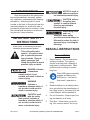
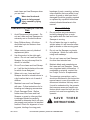
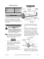
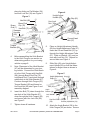
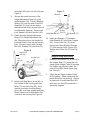
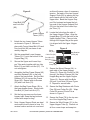
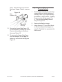
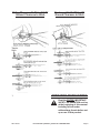
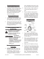
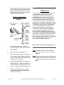
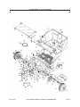
lawn and leaf sweeper
Model 98197
Assembly, Operating, and Maintenance
Instructions
Diagrams within this manual may not be drawn proportionally.
Due to continuing improvements, actual product may differ slightly from the product described herein.
Distributed exclusively by Harbor Freight Tools®.
3491 Mission Oaks Blvd., Camarillo, CA 93011
Visit our website at: http://www.harborfreight.com
Read this material before using this product.
Failure to do so can result in serious injury.
Save this manual.
Copyright© 2008 by Harbor Freight Tools®. All rights reserved. No portion of this
manual or any artwork contained herein may be reproduced in any shape or form
without the express written consent of Harbor Freight Tools.
For technical questions or replacement parts, please call 1-800-444-3353.
Save This Manual
NOTICE is used to
address practices
not related to personal injury.
Keep this manual for the safety warnings and precautions, assembly, operating, inspection, maintenance and cleaning
procedures. Write the product’s serial
number in the back of the manual near the
assembly diagram (or month and year of
purchase if product has no number). Keep
this manual and the receipt in a safe and
dry place for future reference.
CAUTION, without
the safety alert
symbol, is used to address
practices not related to
personal injury.
When using Lawn
and Leaf
Sweepers, basic safety
precautions should always be
followed to reduce the risk of
personal injury, including the
following:
Important Safety
Instructions
In this manual, on the labeling, and all other
information provided with this product:
This is the safety alert
symbol. It is used to alert
you to potential personal
injury hazards. Obey all
safety messages that
follow this symbol to avoid
possible injury or death.
DANGER indicates
a hazardous
situation which, if not
avoided, will result in death or
serious injury.
WARNING
indicates a
hazardous situation which, if
not avoided, could result in
death or serious injury.
CAUTION, used
with the safety
alert symbol, indicates a
hazardous situation which, if
not avoided, could result in
minor or moderate injury.
SKU 98197
Read All Instructions
Personal Safety
1.
Dress Properly - Do not wear loose
clothing or jewelry. They can be
caught in moving parts. Wearing of
long pants is recommended. Wear
protective hair covering to contain
long hair.
2.
dusty.
Wear ANSI-approved safety
goggles and heavy-duty
work gloves. Use face or
dust mask if operation is
3.
Read and adhere to all safety instructions provided by the manufacterer of
the riding mover or the tractor that the
Lawn Sweeper will be attached to.
4.
Do not Overreach - Keep proper footing and balance at all times.
5.
Stay Alert - Watch what you are doing. Use common sense. Do not op-
For technical questions, please call 1-800-444-3353.
Page 2
erate Lawn and Leaf Sweeper when
you are tired.
6.
breakage of parts, mounting, and any
other condition that may affect its operation. A guard or other part that is
damaged should be properly repaired
or replaced by a qualified technician
unless indicated elsewhere in this
manual.
Wear steel toed work
boots to help prevent
injury caused by flying
debris.
Lawn and Leaf Sweeper Use and
Care
General Safety
1.
Do not perform any maintenance,
including changing lines or making repairs while the Leaf and Lawn
Sweeper is moving.
Keep Children Away - All visitors
should be kept at a distance from
work area.
2.
Do not fasten the rope to a pulling
vehicle where it it will become entangled in wheels or other moving parts.
3.
When servicing use only identical
replacement parts.
3.
4.
Use this product in the right application - Do not use Lawn and Leaf
Sweeper for any job except that for
which it is intended.
Do not use the Sweeper on streets
or highways. Watch for traffic while
using near roadways.
4.
Do not use Lawn and Leaf Sweeper
for other than intended use.
5.
Maintain labels and nameplates on
the Lawn and Leaf Sweeper. These
carry important safety information. If
unreadable or missing, contact Harbor Freight Tools for a replacement.
6.
The warnings, precautions, and instructions discussed in this instruction
manual cannot cover all possible conditions and situations that may occur.
It must be understood by the operator
that common sense and caution are
factors which cannot be built into this
product, but must be supplied by the
operator.
1.
Avoid Dangerous Environment - Do
not use Lawn and Leaf Sweepers in
extremely wet or flooded locations.
2.
5.
Do not Force Lawn and Leaf Sweeper - It will do the job better at the rate
for which it was designed.
6.
When not in use, Lawn and Leaf
Sweeper should be stored indoors in
a dry location that is out of reach of
children.
7.
Maintain Lawn and Leaf Sweeper
with care - Follow instructions for lubricating and changing accessories.
8.
Check Damaged Parts - Before
further use of the Lawn and Leaf
Sweeper, a guard or other part that
is damaged should be carefully
checked to determine that it will operate properly and perform its intended
function. Check for alignment of moving parts, binding of moving parts,
SKU 98197
S a v e t h e s e
instructions.
For technical questions, please call 1-800-444-3353.
Page 3
Sweeper Housing
Specifications
Hopper capacity
12 Cubic Feet
Brushes
18-1/4” x 3-1/2”
Wheels
Solid rubber, all
terrain tread
Net Weight
73.8 Lbs.
Figure 1
Sweeper
Housing
Carriage
Bolt (67)
Skirt (4)
Unpacking
When unpacking, check to make sure
that the item is intact and undamaged. If
any parts are missing or broken, please
call Harbor Freight Tools at the number
shown on the cover of this manual as soon
as possible.
Set Up Instructions
Read the entire Important
Safety Instructions
section at the beginning of this
manual including all text under
subheadings therein before set
up or use of this product.
Hitch Tongue (65)
Flat Washer (54)
Hex Lock
Nut (18)
1.
Locate each of the 5/16” Hex lock
Nuts (18) and 5/16” Flat Washers
(54).
2.
Secure the Hitch Tongue (65) to the
Skirt (4) on the sweeper housing.
Insert the 5/16” x 1-1/2” Carriage
Bolts (67) inserted so that the bolt
heads are on the inside of the housing. Slide on Flat Washers (54), and
thread on Hex Lock Nuts (18). Hand
tighten in place-see Figure 1.
Note: For additional information regarding
the parts listed in the following pages,
refer to the Assembly Diagram near
the end of this manual.
Assembly
1.
2.
Due to the weight of the Lawn and
Leaf Sweeper, it is recommended
that an additional adult assist in assembly and set-up.
Assembly of the Lawn and Leaf
Sweeper will require use of the following tools (not included): hex
wrenches, standard screwdriver and
pliers.
SKU 98197
Hex Lock
Nut (18)
Figure 2
Carriage
Bolt (29)
Flat
Washer (54)
3.
Brace Rod (7)
Secure the Brace Rod (7) to the
Sweeper Housing. Slide in Carriage
Bolt (29), and secure Brace Rod in
For technical questions, please call 1-800-444-3353.
Page 4
place by sliding on Flat Washer (54)
and Hex Lock Nut (18)-see Figure 2.
Figure 4
Height Adjust
Handle (69)
Figure 3
Hex Bolt (68)
Grip (45)
Hex Lock
Nut (18)
Brace Rod
Clip (70)
Brace
Rod (7) Hex Bolt (73)
Sweeper
Housing
(65)
Washer
(86)
Curved Head
Bolt (37)
Tongue
Bracket (89)
4.
5.
6.
7.
Place on Height Adjustment Handle
(69) the Height Adjustment Tube (27).
Insert the Curved Head Bolt (37) up
through the Height Adjustment Tube
(27). Slide on Washer (86), and secure with Lock Nut (18). Repeat for
second hole-see Figure 4.
9.
Slide Grip (45) onto Height Adjustment Handle (69) so that the indentations for fingers face as shown in
Figure 4.
Hitch
Bracket (47)
Before assembling the Hitch Bracket
to the Hitch Tongue, see section on
determining position for your towing
vehicle on page 8.
Note: Placement of the Hitch Bracket
(47) will be determined by your towing vehicle. Connect the Hitch Bracket to the Hitch Tongue with Hex Bolt
(68), through Brace Rod Clip (70),
onto Brace Rod (7) and down through
middle hole in the Hitch Bracket (47).
Continue through Hitch Tongue (65),
Tongue Bracket (89) and thread on
Hex Lock Nut (60)-see Figure 3 and
assembly diagram.
Insert Hex Bolt (73) down through the
rear hole of the Hitch Bracket (47),
down through the Hitch Tongue (65)
and secure with Hex Lock Nut (60)see Figure 3.
Tighten down all hardware.
SKU 98197
8.
Figure 5
Height Adjustment Grip (45)
Strap (6)
Bolt (56)
Bolt (71)
Bolt (29)
Angle
Bracket (38)
Lock Washer
(44)
Hex Nut 5/16”
(28)
Bushing
Spacer (30)
Tongue
Bracket (89)Washer (54)
10. Attach the Angle Bracket (38) to the
Hitch Tongue (65) as shown. Secure
For technical questions, please call 1-800-444-3353.
Page 5
using Bolt (29) and Lock Nut (54)-see
Figure 5.
11. Secure the round hole end of the
Height Adjustment Strap (6) to the
Angle Bracket (38). Place a Bushing
Spacer (30) over the end of the Slot
Head Bolt (71) and into the hole in
the Adjustment Strap (6)-see Figure 5
and Assembly Diagram. Secure with
Lock Washer (44) and Hex Nut (28).
12. Finish securing Height Adjustment
Strap (6) to Height Adjustment Handle. Place the slot on the Height Adjustment Strap in line with the square
hole. Secure in place with Carriage
Bolt (29), Washer (54) and Knob (5).
Figure 6
Bag Mount
Arm (48)
Lock
Nut (60)
Hitch Pin
Cotter
Hitch Bracket (47) Pin (75)
Spacers (77)
14. Insert two Spacers (77) between
Hitch Bracket (47) and Hitch Tongue
(65). Insert Hitch Pin (76) down
through the Hitch Bracket, Spacers
(77) and through Hitch Tongue (65).
Secure with Cotter Pin (75)-see Figure 7.
Hopper Bag Assembly
Hex Bolt (73)
13. Attach both Bag Mount Arms (48) to
the outside of the housing with Hex
Bolts (73) and Lock Nut (60). Note
that the notches in the Bag Mount
Arms (48) must face upward and Bag
Mount Arms must be attached to the
outside of the housing-see Figure 6.
SKU 98197
Figure 7
1.
Starting at the center cut in the top of
the Hopper Bag (12), insert the Left
Hand Upper Hopper Tube (9) through
the hopper bag stitched tubes. Repeat for the Right Hand Upper Hopper Tube (8).
2.
Slide the two Upper Hopper Tubes
(8/9) together. Make certain that the
center holes line up perfectly. Secure
in place with Curved Head Bolt (63)
and Hex Lock Nut (80) as shown in
assembly diagram.
For technical questions, please call 1-800-444-3353.
Page 6
as this will cause a loss of necessary
tension. Set each of the two Hopper
Support Rods (50) by placing the top
end of each rod into the hole in the
Upper tube. Bend the Hopper Support Rod outward and snap the bottom end of the Hopper Support Rod
(50) into the hole in the Lower Hopper Tube (11).
Figure 8
Head Bolt (63)
and Lock Nut
(80)
Lower Hopper
Tubes (10/11)
3.
4.
5.
Attach the two Lower Hopper Tubes
as shown in Figure 8. Secure in
place with Curved Head Bolt (63) and
Hex Lock Nut (80) as shown in assembly diagram.
Set the assembled Lower Hopper
Tubes (10/11) onto the bottom of the
Hopper Bag (12).
Secure the Upper and Lower Hopper Tube ends together with two Hex
Bolts (61) and Hex Lock Nut (57). Do
not overtighten.
6.
Assemble the Bag Frame Stamp (49)
and Skirt Retainer (43) to the front
edge of the bag bottom. Set the Skirt
Retainer (43) on top and the Frame
Strap (49). Secure with six Screws
(52) and Lock Nuts (53).
7.
Attach the Bag Frame Strap (49) to
the lower hopper frame. Secure with
Hex Bolt (61) and Lock Nut (57).
8.
Set the bag corners over the lower
hopper tube. Snap the bag bottoms
closed with snaps on bag.
9.
Note: Hopper Support Rods are steel
and require force to bend or bow. Excercise caution and do not over bend
SKU 98197
10. Locate the hole along the side of
the Upper Hopper Tubes. Align the
Hopper Bag (12) with the hole in the
Upper Hopper Tube. Pierce a hole
through the Hopper Bag at the point
it is aligned with the Upper Hopper
Tube.
Cotter
Pin (62)
Figure 9
Clevis Pin (58)
Bag Retainer
Clevis (66)
Lock Nut (55)
Bolt (56)
Mount
Clamp (64)
11. Secure the Mount Clamps (64) to
each side of the Upper Hopper
Tubes (9). Place one Clevis Pin (58)
through the Mount Clamps (64), the
Hopper Bag and the Upper Hopper
Tubes (9). Secure with Hex Bolts
(56) and Lock Nuts (55)-see Figure
9. Repeat for second side.
12. Secure the Bag Retainers with Clevis
Pins (58) and Cotter Pin (62). Wrap
Cotter Pin around Clevis Pin as
shown in Figure 9.
13. Secure the Rope (78) to the top center of the Hopper Bag Frame.
14. Secure the Wind Screen (31) to the
Upper Hopper Tube (9). Stretch out
all four corner loops and snap into
For technical questions, please call 1-800-444-3353.
Page 7
place. Wrap the rear loops around
the Upper Hopper Tube for a secure
fit.
Figure 10
Adjusting Lawn Sweeper to the
Towing Vehicle
1.
The Sweeper must be secured to the
towing vehicle so that the bottom of
the Bag Frame (12) is approximately
level when on a flat surface. The Bag
Frame must be off the ground 3” to
4”. Do not allow the Bag Frame to
drag on the ground.
2.
Remove the Bag for storage.
3.
Adjust Spacers (77) and Hitch Bracket (47) according to the diagram on
page 9. The black line represents the
tractor hitch.
Bag
Retainer (66)
Bag Mount
Arm (48)
15. Secure the Hopper Bag Frame (12)
to the Sweeper by hooking the Clevis
Pins into the notches in the Mount
Arms-see Figure 10.
16. To remove the Hopper Bag Frame
from the Sweeper, flip the Bag Retainers up and remove the Bag-see
Figure 10.
SKU 98197
For technical questions, please call 1-800-444-3353.
Page 8
Riding Mowers with 8” to 10-1/2”
Ground Clearance to Hitch
Tractors with 10-1/2” to 13”
Ground Clearance to Hitch
Tractor
Hitch
1.
Operating Instructions
Read the entire Important
Safety Information section
at the beginning of this manual
including all text under
subheadings therein before set
up or use of this product.
SKU 98197
For technical questions, please call 1-800-444-3353.
Page 9
Brush Height Adjustment
1.
To adjust Sweeper brushes to the
best height, loosen the Height Adjustment Knob (5) and push down on
the Height Adjustment Handle (69) to
raise. For best performance, adjust
the brushes so that they set 1/2”
down into the grass.
parts, damaged and any other condition that may affect its safe operation.
2.
Add a few drops of light machine oil
to the brush shaft bearins twice a
year.
3.
Remove wheels to clean gears every two years. After cleaning, apply
an even coat of light grease. Do not
overtighten wheel bolt and nut upon
reassembly. Wheel must be free to
move in slot with height adjustment.
Dumping the Sweeper
1.
2.
The Sweeper can be dumped easily
without getting off of the rider or tractor. Pull the rope forward to dump.
Removing Wheel
Figure 11
Always dump the Sweeper after each
use. Damp or wet grass and leaves
will cause damage to hopper if stored
for long periods of time.
Maintenance And
Servicing
Procedures not specifically
explained in this manual
must be performed only by a
qualified technician.
To prevent
serious injury
from tool failure:
Do not use damaged
equipment. If abnormal noise
or vibration occurs, have the
problem corrected before
further use.
1.
Pop off Hub Cap (90) with a screw
driver (not included). Remove Jam
Nut (18), Hex Lock Nut and Washer
(19)-see figure 11.
2.
When servicing Wheel gears, do not
remove both wheels at once. Remove one wheel at at a time to prevent use of left-hand parts on righthand side.
3.
Make note of all washers and rings.
4.
The Drive Pin is located inside of the
ratchet gear. When reassembling the
ratchet gear and pin, fill the inside of
the gear with grease. Reassemble
the wheel and rotate it in both directions. The wheel should drive the
brushes only when turned in the for-
Cleaning, Maintenance, and
Lubrication
1.
BEFORE EACH USE, inspect the
general condition of the Lawn and
Leaf Sweeper. Check for loose
screws, misalignment or binding of
moving parts, cracked or broken
SKU 98197
For technical questions, please call 1-800-444-3353.
Page 10
ward direction. If the brushes move
in both directions, then the Drive Pin
is jamming inside the Ratchet Gear.
Make certain that the gear is clean
and greased adequately.
Replacing Brushes
Figure 12
Oil Bearing
here
1.
Replace Brushes one at a time to
avoid misplacing right and left-hand
side gearing.
2.
Remove the Hopper Bag (12).
3.
Tip the Sweeper back on its housing.
Do not remove Hex Bolts which fasten the Double Brush Retainers (40)
to the Brush Shaft (39).
4.
Loosen the Hex Bolts (73) and Hex
Lock Nuts (60). Slide the Brush out
of the retainers, making note of the
position of the bristles-see Figure 12.
5.
Install new Brush, making certain
overlapping bristles are positioned
the same as before.
SKU 98197
PLEASE READ THE FOLLOWING
CAREFULLY
The manufacturer and/or distributor
has provided the parts list and
assembly diagram in this manual as
a reference tool only. Neither the
manufacturer or distributor makes
any representation or warranty of
any kind to the buyer that he or she
is qualified to make any repairs to the
product, or that he or she is qualified
to replace any parts of the product.
In fact, the manufacturer and/or
distributor expressly states that
all repairs and parts replacements
should be undertaken by certified
and licensed technicians, and not by
the buyer. The buyer assumes all risk
and liability arising out of his or her
repairs to the original product or
replacement parts thereto, or arising
out of his or her installation of
replacement parts thereto.
Record Product’s Serial Number Here:
Note: If product has no serial number,
record month and year of purchase
instead.
Note: Some parts are listed and shown for
illustration purposes only, and are not
available individually as replacement
parts.
For technical questions, please call 1-800-444-3353.
Page 11
Part Q’ty Description
1
4 Brush
2
1 Pinion Gear-R.H.
3
1 Pinion Gear-L.H.
4
1 Skirt
5
1 Height Adj. Knob
6
1 Height Adj. Strap
7
1 Brace Rod
8
1 Upper Hopper Tube R.H.
9
1 Upper Hopper Tube L.H.
10
1 Lower Hopper Tube R.H.
11
1 Lower Hopper Tube L.H.
12
1 Hopper Bag
13
16 Pop Rivet
14
2 Bearing Retainer
15
4 Retaining Ring
16
6 Flat Washer
17
4 Hex Bolt M8x20
18
9 Hex Lock Nut M8
19
2 Flat Washer
20
2 Flat Washer Ø10xØ26
21
2 Washer Ø10
22
2 Hex Bolt
23
2 Jam Nut
24
4 Hex Bolt M6x25
25
26
27
28
16
2
1
1
SKU 98197
Hex Lock Nut M6
Hex Lock Nut M10
Height Adj Tube
Hex Nut M8
Part Q’ty Description
29
3 Carriage Bolt M8x20
30
1 Bushing Spacer
31
1 Windscreen
32
2 Brush Shaft Bushing
33
1 Rear Support Brace
34
1 Wrapper
35
2 Dust Cover Assy
36
8 Hex Bolt M6x20
37
2 Curved Hd. Bolt M8x40
38
1 Angle Bracket
39
1 Brush Shaft
40
4 Brush Retainer (double)
41
8 Brush Retainer (single)
42
2 Wheel Assembly
43
1 Skirt Retainer
44
1 Lock Washer Ø8 I.D.
45
1 Grip
46
2 Hub Cap
47
1 Hitch Bracket
48
2 Bag Mount Arm
49
1 Bag Frame Strap
50
2 Hopper Support Rod
51
2 Dowel Pin
52
6 Truss Hd. Slotted Screw
M5x15
53
6 Hex Lock Nut M5
54
6 Flat Washer Ø8
55
4 Hex Lock Nut M8
56
5 Hex Bolt M8x20
For technical questions, please call 1-800-444-3353.
Page 12
Part Q’ty Description
57
2 Hex Lock Nut M6
58
2 Clevis Pin Ø10x80
59
2 Hex Bolt M10x20
60
8 Hex Lock Nut M10
61
2 Hex Bolt M6x35
62
2 Cotter Pin Ø3x20
63
2 Curved Hd. Bolt M6x25
64
4 Hopper Mount Clamp
65
1 Hitch Tongue
66
2 Bag Retainer Clevis
67
2 Carriage Bolt M8x40
68
1 Hex Bolt M10x40
69
1 Height Adj. Handle
70
1 Clip Brace Rod
71
1 Sl. Truss Hd. Bolt M8x25
72
2 Carriage Bolt M6x16
73
5 Hex Bolt M10x20
74
2 Hex Bolt M6x12
75
1 Hairpin Cotter Ø4
SKU 98197
Part Q’ty Description
76
1 Hitch Pin
77
2 Spacer
78
1 Hopper Rope
79
2 Flat Washer
80
2 Hex Lock Nut
81
2 Flat Washer
82
4
Hex Bolt M8x15
83
1 End Plate L.H.
84
1 End Plate R.H.
85
1 Hitch Tube
86
1 Bowed Washer
87
2 Spacer
88
2 Spacer
89
1 Tongue Bracket
90
4 Wheel Bearing
91
2 Washer, Special
92
2 Washer Ø16
For technical questions, please call 1-800-444-3353.
Page 13
ASSEMBLY DIAGRAM
SKU 98197
For technical questions, please call 1-800-444-3353.
Page 14